Conventional Machining Methods for Rapid Prototyping
Conventional Machining Methods for Rapid Prototyping
Conventional Machining Methods for Rapid Prototyping

You also want an ePaper? Increase the reach of your titles
YUMPU automatically turns print PDFs into web optimized ePapers that Google loves.
9<br />
<strong>Conventional</strong> <strong>Machining</strong> <strong>Methods</strong> <strong>for</strong> <strong>Rapid</strong> <strong>Prototyping</strong> and Direct<br />
Manufacturing<br />
associated with process planning, but it assures the absolute collision-free nature of the<br />
approach. From each orientation, some, but not all of the part surfaces will be visible.<br />
The goal is to machine the part from enough orientations, such that, after all toolpaths are<br />
complete, all surfaces have been fully machined from at least one orientation. For each<br />
orientation, there is no particular plan <strong>for</strong> a set of feature machining operations; rather,<br />
geometry is machined using simple 2½D layer-based toolpaths. Unlike the existing rapid<br />
prototyping methods, CNC machining is a subtractive process; there<strong>for</strong>e, one can only<br />
remove the material around the periphery of a part (visible cross section of the part).<br />
The process plan stage includes axis analysis, visibility (orientation) analysis,<br />
sacrificial fixture design, and tooling selection. Visibility (orientation) analysis is a<br />
challenging problem <strong>for</strong> CNC-RP process planning. A desired goal is to machine the part<br />
with the fewest number of orientations or setups. The critical data required <strong>for</strong> processing<br />
a part using this method is the number and orientation of the two-and-a-half-dimensional<br />
(2½-D) toolpaths necessary to machine all the surfaces (Frank, Wysk et al. 2006). The<br />
feature-free nature of this method suggests that it is unnecessary to have any surface be<br />
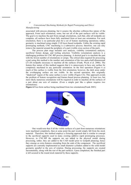
completely machined in any particular orientation. In the first operation (Figure 6 a)<br />
much of this surface is visible from the first orientation; however, the dark areas under<br />
the overhanging surface are not visible. In the second operation, this originally<br />
"shadowed" region of the same surface is now visible (Figure 6 b). This approach avoids<br />
the problem of feature recognition and feature-based process planning. At least two, but<br />
more likely numerous orientations will be required in order to machine all the surfaces of<br />
a part about one axis of rotation. (Even a simple part like a sphere requires two<br />
orientations).<br />
Figure 6 Free-<strong>for</strong>m surface being machined from two orientations(Frank 2003)<br />
One would note that if all the visible surfaces of a part from numerous orientations<br />
were machined completely, then at some point the part would simply fall from the stock<br />
material. There<strong>for</strong>e, this method employs a fixturing approach that is similar in concept<br />
to the sacrificial supports used in many existing additive rapid prototyping processes.<br />
However, in CNC-RP the supports are not added to the physical model during<br />
processing, rather, they are added to the CAD model prior to toolpath planning; hence<br />
they emerge as extra features extending from the ends of the component. The sacrificial<br />
supports are currently implemented as small diameter cylinders added to the solid model<br />
geometry parallel to the axis of rotation. During processing, the supports are created<br />
incrementally, along with the rest of the part surfaces. Upon completion, the finished part<br />
is left secured to the round stock material by these supports.