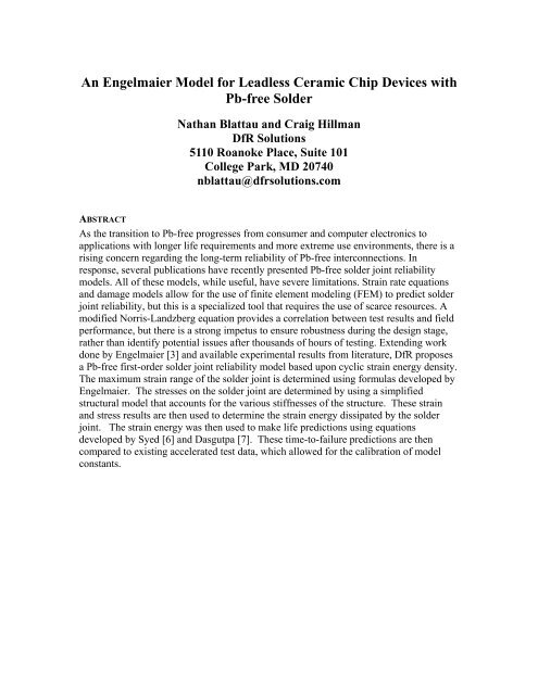
An Engelmaier Model for Leadless Ceramic Chip ... - DfR Solutions
An Engelmaier Model for Leadless Ceramic Chip ... - DfR Solutions
An Engelmaier Model for Leadless Ceramic Chip ... - DfR Solutions

Create successful ePaper yourself
Turn your PDF publications into a flip-book with our unique Google optimized e-Paper software.
<strong>An</strong> <strong>Engelmaier</strong> <strong>Model</strong> <strong>for</strong> <strong>Leadless</strong> <strong>Ceramic</strong> <strong>Chip</strong> Devices with<br />
Pb-free Solder<br />
Nathan Blattau and Craig Hillman<br />
<strong>DfR</strong> <strong>Solutions</strong><br />
5110 Roanoke Place, Suite 101<br />
College Park, MD 20740<br />
nblattau@dfrsolutions.com<br />
ABSTRACT<br />
As the transition to Pb-free progresses from consumer and computer electronics to<br />
applications with longer life requirements and more extreme use environments, there is a<br />
rising concern regarding the long-term reliability of Pb-free interconnections. In<br />
response, several publications have recently presented Pb-free solder joint reliability<br />
models. All of these models, while useful, have severe limitations. Strain rate equations<br />
and damage models allow <strong>for</strong> the use of finite element modeling (FEM) to predict solder<br />
joint reliability, but this is a specialized tool that requires the use of scarce resources. A<br />
modified Norris-Landzberg equation provides a correlation between test results and field<br />
per<strong>for</strong>mance, but there is a strong impetus to ensure robustness during the design stage,<br />
rather than identify potential issues after thousands of hours of testing. Extending work<br />
done by <strong>Engelmaier</strong> [3] and available experimental results from literature, <strong>DfR</strong> proposes<br />
a Pb-free first-order solder joint reliability model based upon cyclic strain energy density.<br />
The maximum strain range of the solder joint is determined using <strong>for</strong>mulas developed by<br />
<strong>Engelmaier</strong>. The stresses on the solder joint are determined by using a simplified<br />
structural model that accounts <strong>for</strong> the various stiffnesses of the structure. These strain<br />
and stress results are then used to determine the strain energy dissipated by the solder<br />
joint. The strain energy was then used to make life predictions using equations<br />
developed by Syed [6] and Dasgutpa [7]. These time-to-failure predictions are then<br />
compared to existing accelerated test data, which allowed <strong>for</strong> the calibration of model<br />
constants.
INTRODUCTION<br />
One of the original assumptions of simple distance to neutral point solder reliability<br />
models is that of complete stress relaxation, i.e. the differential expansion between the<br />
part and the printed wiring board is directly related to the shear strain in the solder joint.<br />
After many years of experience with SnPb solders it has been proven to provide fairly<br />
good thermal cycling fatigue predictions. However, due to the increased stiffness of<br />
SnAgCu solder this is unlikely to provide adequate and may yield overly conservative<br />
life predictions. The primary goal of this study is to generate a simplified DNP model<br />
that accounts <strong>for</strong> the increased stiffness of the Pb-free solder.<br />
The model is broken down into four portions, a solder shear stress equation, a solder<br />
strain range computation, a strain energy computation and a solder fatigue equation. The<br />
solder shear stress equation is used to determine the amount of shear stress available to<br />
drive the de<strong>for</strong>mation of the solder joint during temperature cycling. The solder strain<br />
range computation is then used to convert that stress, along with the thermal cycling<br />
details (temperature, dwell times) to determine the strain energy per thermal cycle. This<br />
strain energy is used in a solder fatigue equation to determine the number of cycles to<br />
failure.<br />
MODEL DEVELOPMENT<br />
Solder Shear Stress Computations<br />
The structure of the component attached to the printed wiring board is represented by a<br />
combination of axial and shear springs, consisting of:<br />
• Component axial stiffness<br />
• Solder shear stiffness<br />
• Bond-pad shear stiffness<br />
• Printed wiring board bond pad interface stiffness (foundation stiffness)<br />
• Printed wiring board axial stiffness<br />
A schematic representation of the structure is shown in Figure 1. To this structure the<br />
global de<strong>for</strong>mation due to the CTE mismatch is applied and the stress in the solder joint<br />
is determined using compatibility of displacements. Bending of the substrate and<br />
component are ignored since the members are very short (aspect ratios less than 10), and<br />
will have axial and shear de<strong>for</strong>mations dominating.
Figure 1: Simplified Structure<br />
The component displacement due to a temperature rise is shown in Equation 1.<br />
U<br />
1<br />
= α ⋅ ∆ T ⋅ L<br />
1<br />
D +<br />
FLD<br />
E A<br />
Equation 1: Component displacement equation<br />
1<br />
1<br />
Where U 1 is the displacement, α 1 is the coefficient of thermal expansion (CTE), ∆T<br />
temperature change, L D is one-half the component length, F is the <strong>for</strong>ce, E 1 is the elastic<br />
modulus of component and A 1 is the cross-sectional area of the component. The crosssectional<br />
area of the component is its thickness, h c multiplied by its width.<br />
The board displacement due to a temperature rise is shown in Equation 2.<br />
U<br />
2<br />
= α ⋅ ∆θ<br />
⋅ L<br />
2<br />
D −<br />
FL<br />
E A<br />
Equation 2: Board displacement<br />
2<br />
2<br />
Where U 2 is the displacement, α 2 is the CTE, ∆T temperature change, F is the <strong>for</strong>ce, E 2 is<br />
the elastic modulus of printed wiring board, and A 2 is the cross-sectional area of the<br />
printed wiring board. The area of the board is calculated by multiplying the thickness, h p<br />
by two times the bond pad width.<br />
De<strong>for</strong>mation of the interconnect <strong>for</strong> a given shear <strong>for</strong>ce - F, the interconnect includes the<br />
effect of the solder, copper and board interface stiffness and is computed using Equation<br />
3.
U<br />
i<br />
=<br />
Fhs<br />
A G<br />
s<br />
s<br />
+<br />
Fhb<br />
A G<br />
b<br />
b<br />
⎛ ⎞<br />
⎜<br />
2 −ν<br />
+ F ⎟<br />
⎝ 9⋅G<br />
pa<br />
⎠<br />
Equation 3: Interconnect displacement equation<br />
Where U i is the displacement, h S is the solder joint thickness (assumed to be 4 mils), A S<br />
is the effective solder joint area, G S is solder shear modulus, A b is the copper bond pad<br />
area, h b is the copper thickness (0.035 mm), G b is the copper shear modulus. The<br />
additional equation represents the effective foundation stiffness of the bond-pad to PWB<br />
interface and is the shear stiffness of a rigid square on a half space [1, 2], where ν is the<br />
Poisson’s ratio and G p is the shear modulus of the printed wiring board and a is one half<br />
the side length of the bond pad.<br />
The <strong>for</strong>ce F can then be solved <strong>for</strong> using the following compatibility equation shown in<br />
Equation 4.<br />
⎛<br />
L<br />
2 −ν<br />
⎞⎞<br />
( ) ⎜ D D s b<br />
α 2 − α1<br />
⋅ ∆T<br />
⋅ LD<br />
= F ⋅<br />
+ + + +<br />
⎜<br />
⎟<br />
⎟ ⎝ E1<br />
A1<br />
E2<br />
A2<br />
AsGs<br />
AbGb<br />
⎝ 9 ⋅ Gba<br />
⎠⎠<br />
Equation 4: Displacement compatibility equation<br />
The shear stress on the solder is then calculated by dividing the <strong>for</strong>ce by the effective area<br />
of the solder joint. The effective solder joint area, A S is assumed to be 75% of the pad<br />
area.<br />
Solder Strain Calculations<br />
The shear strain in the solder is computed using equations developed by Werner<br />
<strong>Engelmaier</strong> <strong>for</strong> leadless components. This is then multiplied by the previously calculated<br />
shear stress to determine the cyclic strain energy. The basic calculation <strong>for</strong> strain range is<br />
shown in Equation 5.<br />
LD<br />
∆γ<br />
= C ∆α∆T<br />
hs<br />
Equation 5: Strain range calculation [3]<br />
Where C is 0.5, an empirical correction factor, L D is ½ the length of the component, h s is<br />
the solder joint height (assumed to be 0.1016 mm or 4 mils), and ∆α∆T is the differential<br />
thermal expansion between the component and substrate. This strain is assumed to be the<br />
maximum strain that can be developed in the solder joint.<br />
L<br />
h<br />
h<br />
⎛
Solder Strain Energy Calculations<br />
The strain energy density dissipated during the thermal cycle is assumed to be<br />
approximately equal to the <strong>for</strong>mula shown in Equation 6.<br />
∆W ≅ ∆γ ⋅τ<br />
Equation 6: Strain energy density<br />
Life Predictions<br />
The energy dissipated per thermal cycle is used to make fatigue life predictions using<br />
damage laws developed by Syed [6]. Syed developed two damage equations <strong>for</strong> strain<br />
energy density based upon two different creep strain rate equations. The one used in this<br />
study is based upon the double power law creep model shown in Equation 7.<br />
N<br />
f<br />
−<br />
( 0.0015w<br />
) 1<br />
= acc<br />
Equation 7: Strain energy damage equation [6]<br />
Additional calculations using an energy damage law developed by Zhang and Dasgupta<br />
[7] were also done as a comparison. The damage law they proposed is shown in<br />
Equation 8.<br />
⎛ wacc<br />
⎞<br />
N f = ⎜ ⎟<br />
⎝ 5920 ⎠<br />
Equation 8: Strain energy damage equation [7]<br />
−<br />
1<br />
1.3
VALIDATION<br />
Validation of the model was per<strong>for</strong>med by comparing predictions to experimental<br />
findings from available publications.<br />
Failure Data<br />
Data on the thermal cycling behavior of leadless chip resistors attached with SnAgCu is<br />
outlined in Table 1. This data was plotted and is displayed as a function of component<br />
size and temperature cycle in Figure 2 through Figure 4. All datasets cited in Table 1,<br />
except <strong>for</strong> Franhofer used a SnAgCu alloy with an elevated silver content (3.9 or 3.8).<br />
Based on recent data published by IPC, providing that the SnAgCu composition is<br />
between Sn3.9Ag0.7Cu and Sn3.0Ag0.5Cu, the time to failure behavior during<br />
temperature cycling seems to be relatively insensitive to the exact alloy content.<br />
Comparing the in<strong>for</strong>mation retrieved from the various papers can be difficult as a number<br />
of experimental designs were setup to assess the influence of parameters separate from<br />
the component, interconnect or environment. For example, the dataset from Woodrow<br />
(reference 9) included varying the Pb-free solderability plating between immersion silver<br />
(ImAg), organic solderability preservative (OSP), and electroless nickel/immersion gold<br />
(ENIG). A similar ef<strong>for</strong>t was made by Schubert (reference 17). Other non-environmental<br />
drivers investigated included cooling rates (reference 13) and the number of reflows<br />
(reference 16).
Table 1: Time to failure data <strong>for</strong> thermally cycled leadless chip resistors attached<br />
with SnAgCu solder<br />
Organization Ref Size<br />
Min Max<br />
Temp Temp<br />
Ramp Dwell Eta Beta<br />
Auburn 8 2512 -40°C 125°C 20 min 20 min 5114 2.839<br />
Auburn 8 2512 -40°C 150°C 20 min 20 min 2158 2.819<br />
Boeing 9 1206 -55°C 125°C 25 min 15 min 3866 1.975<br />
Boeing 9 1206 -55°C 125°C 25 min 15 min 5015 2.201<br />
Boeing 9 1206 -55°C 125°C 25 min 15 min 4523 2.274<br />
Motorola 10 2512 0°C 100°C 15 min 15 min 3063 2.836<br />
Motorola 10 2512 -40°C 125°C 15 min 15 min 752 4.391<br />
Motorola 10 2512 -55°C 125°C 10 sec 5 min 681 3.950<br />
Sanmina 11 2512 -40°C 125°C 15 min 5 min 1374 1.696<br />
U. of Toronto 12 2512 0°C 100°C 7 min 5 min 3634 3.823<br />
U. of Toronto 12 2512 0°C 100°C 1 min 5 min 3993 3.909<br />
U. of Toronto 12 2512 -40°C 125°C 1.5 min 5 min 1089 5.646<br />
U. of Toronto 13 2512 0 100°C 7 min 5 min 5958 3.484<br />
U. of Toronto 13 2512 0 100°C 7 min 5 min 4425 2.548<br />
U. of Toronto 14 2512 0 100°C 10 min 6 min 3350 4.65<br />
NPL 15 2512 -55°C 125°C N/A N/A 1450 2.4<br />
NPL 16 1206 -55°C 125°C 18 min 5 min 3403 3.528<br />
NPL 16 1206 -55°C 125°C 18 min 5 min 2513 5.033<br />
Franhofer 17 1206 -40°C 150°C 12 min 12 min 5072 3 1<br />
Franhofer 17 1206 -40°C 150°C 12 min 12 min 5440 3<br />
1 Estimated. Eta not provided in original paper
Percentage Failed<br />
100<br />
90<br />
80<br />
70<br />
60<br />
50<br />
40<br />
30<br />
20<br />
10<br />
0<br />
0 2000 4000 6000 8000<br />
Thermal Cycles<br />
2512 <strong>Chip</strong> Resistor<br />
SnAgCu Solder<br />
FR4 Board<br />
-55C/-40C to 125C/150C<br />
Ref 1 (-40/150)<br />
Ref 3 (-40/125)<br />
Ref 3 (-55/125)<br />
Ref 4 (-40/125)<br />
Ref 5 (-40/125)<br />
Ref 7 (-55/125)<br />
Ref 1 (-40/125)<br />
Figure 2: Time to failure <strong>for</strong> 2512 chip resistors attached with SnAgCu solder and<br />
subjected to severe temperature cycles<br />
100<br />
90<br />
80<br />
Percentage Failed<br />
70<br />
60<br />
50<br />
40<br />
30<br />
Ref 3<br />
Ref 5 (14C/min)<br />
Ref 5 (95C/min)<br />
Ref 6 (3.8C/min)<br />
Ref 6 (6.8C/min)<br />
20<br />
10<br />
0<br />
0 2000 4000 6000 8000<br />
Thermal Cycles<br />
2512 <strong>Chip</strong> Resistor<br />
SnAgCu Solder<br />
FR4 Board<br />
0C to 100C<br />
Figure 3: Time to failure <strong>for</strong> 2512 chip resistors attached with SnAgCu solder and<br />
subjected to moderate temperature cycles
Percentage Failed<br />
100<br />
90<br />
80<br />
70<br />
60<br />
50<br />
40<br />
30<br />
20<br />
10<br />
0<br />
0 2000 4000 6000 8000<br />
Thermal Cycles<br />
1206 <strong>Chip</strong> Resistor<br />
SnAgCu Solder<br />
FR4 Board<br />
-55C/-40C to 125C/150C<br />
Ref 2 (ImAg, -55/125)<br />
Ref 2 (OSP, -55/125)<br />
Ref 2 (ENIG, -55/125)<br />
Ref 8 (1X Reflow, -55/125)<br />
Ref 8 (2X Reflow, -55/125)<br />
Ref 9 (ENIG, -40/150)<br />
Ref 9 (HAL, -40/150)<br />
Ref 9 (ImAg, -40/150)<br />
Figure 4: Time to failure <strong>for</strong> 1206 chip resistors attached with SnAgCu solder and<br />
subjected to severe temperature cycling<br />
Several preliminary findings were derived from an initial review of the validation data.<br />
Ramp rates were found to have a relatively negligible impact on time-to-failure when<br />
compared across several datasets. In addition, thermal cycles with a maximum<br />
temperature above 125°C did not consistently result in a shorter lifetime. This may<br />
suggest that the current standard of maintaining temperatures below 125°C during<br />
accelerated testing of SnPb solder interconnections may also be valid <strong>for</strong> SnAgCu solder<br />
interconnections. In the same regards, thermal cycles with minimum temperatures below<br />
-40°C did also not seem to reduce the time to failure significantly. Other drivers, such as<br />
solderability plating and cooling rates, were also found to have a negligible or secondary<br />
effect when compared to environmental and component parameters.<br />
These findings should only be considered preliminary as there are two major limitations<br />
to the datasets that were identified. The first limitation was that none of the publications<br />
provided all test parameters necessary to assess the relevancy of the time to failure<br />
in<strong>for</strong>mation. Data that was found to be absent included board thickness, board coefficient<br />
of thermal expansion (CTE), procedure <strong>for</strong> monitoring failure, number of samples tested,<br />
number of samples failed, and validation that failures were not at other locations (such as<br />
vias). <strong>An</strong>d almost all the publications failed to provide details on the solder volume, such<br />
as board bond pad dimensions, stencil thickness, or solder joint height. This absence of<br />
data can be critical, as all predictive models <strong>for</strong> long-term reliability of SnAgCu solder<br />
depend on test results to validate their output. Lack of reliable data can result in a lack of<br />
reliable end-of-life models and should drive professional organizations, such as SMTA,<br />
IEEE, IPC, and IMAPS, to consider a global specification on required data <strong>for</strong>mats when<br />
reporting the results of reliability testing.
The second limitation was the lack of repeatability. Repeatability and reproducibility<br />
(R&R) have become a standard practice in manufacturing to ensure a sufficient level of<br />
quality control. While the cost and time associated with temperature cycling to failure can<br />
definitively hinder the implementation of R&R, it should be strongly considered as a<br />
review of the literature seems to identify several examples of test data that do not<br />
correlate with test results from other publications and may not be repeatable.<br />
Validation Example<br />
Two components were studied to compare the model predictions to the failure data, a<br />
2512 and a 1206 ceramic resistor. The material properties <strong>for</strong> various parts of the<br />
assembly were assumed to be the values shown in Table 2, which are typical of values<br />
found in literature.<br />
Material<br />
Elastic Modulus<br />
(MPa)<br />
Table 2: Material Properties<br />
Shear Modulus<br />
(MPa)<br />
Poisson’s<br />
Ration<br />
Coefficient of<br />
Thermal Expansion<br />
(°C/ppm)<br />
SnAgCu 50000 21200 0.36 20<br />
Alumina 300000 115400 0.3 6<br />
FR-4 17000 7200 0.18 16<br />
Copper 120000 44117 0.3 21
The geometric variables (component dimensions) used in the model are shown in Table<br />
3.<br />
Table 3: Geometric Variables<br />
Variable 2512 Resistor 1206 Resistor<br />
Component<br />
Length 6.35 mm 3.05 mm<br />
Width 3.05 mm 1.52 mm<br />
Thickness 1.5 mm 1.2 mm<br />
Copper Bond Pad<br />
Thickness 0.035 mm 0.035 mm<br />
Length 2 mm 1.5 mm<br />
Width 3.05 mm 1.52 mm<br />
Printed Wiring Board<br />
Thickness 1.6 mm 1.6 mm<br />
Solder Joint<br />
Length 1.5 mm 1.125 mm<br />
Width 3.05 mm 1.52 mm<br />
Thickness 0.1016 mm 0.1016 mm<br />
Some typical results <strong>for</strong> the solder shear stress, inelastic strain energy and life predictions<br />
are shown in Table 4 <strong>for</strong> a -55 to 125°C thermal cycle.<br />
Table 4: <strong>Model</strong> Results<br />
Component 2512 1206<br />
∆T 180 180<br />
∆γ 0.0225 0.0108<br />
τ 20.3 MPa 19.9 MPa<br />
∆W 0.572 0.269<br />
N f [6] 1315 cycles 2792 cycles<br />
N f [7] 1382 cycles 2468 cycles<br />
As shown in the table the maximum stress developed in the solder joint only decreases<br />
slightly as the component size shrinks.
A comparison of predictions from the <strong>DfR</strong> reliability model and experimental data from<br />
Table 1 is displayed in Figure 5. The data shows a very strong fit to the predictive results,<br />
especially considering that no iterative fitting to the data was per<strong>for</strong>med be<strong>for</strong>e this<br />
comparison was per<strong>for</strong>med. Three data points lie outside the 2X banding, two of which<br />
correspond to thermal cycling that were conducted up to 150°C, which may be close to or<br />
beyond the glass transition temperature of the circuit board; the one data point that falls<br />
well away from the 2X band is from reference 1. Comparing the results from this<br />
reference to other results from other organizations, as shown in Figure 2, seems to<br />
suggest that some unknown aspect of the test setup or conditions resulted in unexpectedly<br />
much longer times to failure. Both the energy models gave adequate life predictions.<br />
Figure 5: Validation of <strong>DfR</strong> end-of-life model <strong>for</strong> thermally cycled leadless chip<br />
components (red lines indicate 2X bands)
DISCUSSION<br />
As shown by the results the model provides a relatively good estimate of the fatigue<br />
behavior of the leadless chip resistors as a function component size and thermal cycle <strong>for</strong><br />
SnAgCu using calculations that can be easily implemented into a spreadsheet or simple<br />
calculator. This model adds in the effect of the printed wiring board to solder bond pad<br />
by using a foundation shear stiffness equation. <strong>An</strong> example of the life predictions <strong>for</strong> a<br />
2512 resistor at various temperature deltas is shown in Figure 6.<br />
Figure 6: Life predictions <strong>for</strong> 2512 resistor as a function of delta T<br />
The model is currently undergoing minor modifications to account <strong>for</strong> dwell times.<br />
Additional work is being done to check the sensitivity of the model to various geometric<br />
parameters and some modification to the strain range calculation may be implemented.<br />
Additional work in using the stress calculation <strong>for</strong> doing 2 nd order predictions is also<br />
planned so that stress strain hysteresis loops can be generated <strong>for</strong> improved strain energy<br />
calaculations.
REFERENCES<br />
1. Wolf, J.P. 1988. Soil Structure Interaction <strong>An</strong>alysis in Time Domain, Prentice-Hall,<br />
Englewood Cliffs, NJ.<br />
2. Gazetas, G., “Formulas and Charts <strong>for</strong> Impedances of Surface and Embedded<br />
Foundations,” J. Geotech. Engng., 1991, ASCE, 117(9), 1363-1381.<br />
3. <strong>Engelmaier</strong>, W., "Chap. 17: Solder Attachment Reliability, Accelerated Testing, and<br />
Result Evaluation" in Solder Joint Reliability - Theory and Applications, edited by Lau,<br />
J. H., Van Nostrand Reinhold, New York, 1991, pp. 545-587.<br />
4. "Guidelines <strong>for</strong> Accelerated Reliability Testing of Surface Mount Solder Attachments,"<br />
IPC-SM-785, Institute <strong>for</strong> Interconnecting and Packaging Electronic Circuits,<br />
Lincolnwood, IL, July 1992.<br />
5. Jih, E. and Pao, Y. H., June 1995 “Evaluation of Design Parameters <strong>for</strong> <strong>Leadless</strong> <strong>Chip</strong><br />
Resistors Transactions of the ASME Journal of Electronic Packaging, pp. 94-99, Vol.<br />
117.<br />
6. Syed, A., “Accumulated Creep Strain and Energy Density Based Thermal Fatigue Life<br />
Prediction <strong>Model</strong>s <strong>for</strong> SnAgCu Solder Joints,” ECTC 2004, pp. 737-746 - corrected.<br />
7. Qian Zhang, Abhijit Dasgupta, Dave Nelson, and Hector Pallavicini, “Systematic<br />
Study on Thermo-Mechanical Durability of Pb-Free Assemblies: Experiments and FE<br />
<strong>An</strong>alysis” Journal of Electronic Packaging, December 2005, Vol. 127, pp. 415 – 429<br />
8. Suhling, et. al., “Thermal cycling reliability of lead free chip resistor solder joints”,<br />
Soldering and SMT, vol. 16, no. 2, pp. 77–87, Jun. 2004.<br />
9. Woodrow, “Reliability and Leachate Testing of Lead-Free Solder Joints”, IPC<br />
10. Swan, et. al. ,”Development of Lead-Free Peripheral Leaded and PBGA Components<br />
to Meet MSL3 at 260° C Peak Reflow Profile”, IPC APEX 2001<br />
11. Unknown, RoHS Readiness, June 2004, update, Web-based<br />
12. Qi, et al., “Temperature profile effects in accelerated thermal cycling of SnPb and Pbfree<br />
solder joints”, Microelectronics Reliability (2005)<br />
13. Qi, et. al., ”Accelerated Thermal Fatigue of Lead-Free Solder Joints as a Function of<br />
Reflow Cooling Rate”, Journal of ELECTRONIC MATERIALS, Vol. 33, No. 12,<br />
2004<br />
14. Qi, et. al., ”Accelerated Thermal Cycling of Tin-Lead and Lead-Free Solder Joints”<br />
15. Dusek et. al., “Compatibility of Lead-Free Alloys with Current PCB Materials”,<br />
IMAPS 2002, pp. 110-115<br />
16. Dusek, et. al., “Effect of PCB Finish, Processing and Microstructure on Lead-Free<br />
Solder Joint Reliability”, NPL Report, September 2005<br />
17. Schubert et. al., IMAPS