TANDBERG Edge 95-85-75 MXP User Manual (F5).pdf - Expoficina
TANDBERG Edge 95-85-75 MXP User Manual (F5).pdf - Expoficina
TANDBERG Edge 95-85-75 MXP User Manual (F5).pdf - Expoficina

You also want an ePaper? Increase the reach of your titles
YUMPU automatically turns print PDFs into web optimized ePapers that Google loves.
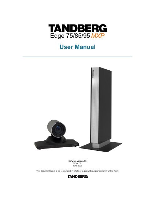
<strong>User</strong> <strong>Manual</strong><br />
Software version <strong>F5</strong><br />
D13947.01<br />
June 2006<br />
This document is not to be reproduced in whole or in part without permission in writing from:
<strong>TANDBERG</strong> <strong>Edge</strong> <strong>75</strong>/<strong>85</strong>/<strong>95</strong> <strong>MXP</strong><br />
Trademarks and Copyright<br />
All rights reserved. This document contains information that is proprietary to <strong>TANDBERG</strong>. No part<br />
of this publication may be reproduced, stored in a retrieval system, or transmitted, in any form, or<br />
by any means, electronically, mechanically, by photocopying, or otherwise, without the prior<br />
written permission of <strong>TANDBERG</strong>. Nationally and internationally recognized trademarks and<br />
trade names are the property of their respective holders and are hereby acknowledged.<br />
Third Party Software<br />
Amended / Expanded Copyright notices for third-party software on the <strong>TANDBERG</strong> <strong>MXP</strong> systems<br />
are listed below:<br />
Full copies of the licenses and warranty statements are located on the product CD in the the<br />
license files directory.<br />
The non-commercial third party code is distributed in binary form under the terms of non-copyleft<br />
style open source licenses such as BSD, Artistic or MIT/X Consortium.<br />
The product also has some binary code distributed under the terms of the GNU public license<br />
with an exemption which allows static links to non-copyleft commercial code.<br />
In accordance with section (3) of the GNU General Public License, copies of such code will be<br />
provided upon request by contacting <strong>TANDBERG</strong>. Please contact us by using the Online Support<br />
section at www.tandberg.net or the “contact us” section of this manual. Please provide USD<br />
10.00 for media and shipping.<br />
Agfa<br />
Contains iType from Monotype Imaging Corporation.<br />
CMU-SNMP<br />
Copyright 1988, 1989, 1991, 1992 by Carnegie Mellon University All Rights Reserved<br />
CMU-SNMP is distributed under the terms of the CMU SNMP license, which is an open source license similar to a BSD or<br />
X Consortium License.<br />
Dropbear - an SSH2 server<br />
Copyright (c) 2002,2003 Matt Johnston All rights reserved.<br />
The Dropbear SSH2 server is distributed under the terms of the Dropbear License, which is a MIT/X Consortium style<br />
open source license.<br />
ii
<strong>User</strong> <strong>Manual</strong><br />
eCos<br />
eCos, the Embedded Configurable Operating System.<br />
Copyright (C) 1998, 1999, 2000, 2001, 2002, 2003 Red Hat, Inc.<br />
Copyright (C) 2002, 2003 John Dallaway<br />
Copyright (C) 2002, 2003 Nick Garnett<br />
Copyright (C) 2002, 2003 Jonathan Larmour Copyright (C) 2002, 2003 Andrew Lunn Copyright (C) 2002, 2003 Gary<br />
Thomas Copyright (C) 2002, 2003 Bart Veer<br />
Copyright (c) 1982, 1986, 1991, 1993 The Regents of the University of California. All rights reserved.<br />
(c) UNIX System Laboratories, Inc.<br />
All or some portions of this file are derived from material licensed to the University of California by American Telephone<br />
and Telegraph Co. or Unix System Laboratories, Inc. and are reproduced herein with the permission of UNIX System<br />
Laboratories, Inc.<br />
Copyright (C) 19<strong>95</strong>, 1996, 1997, and 1998 WIDE Project. * All rights reserved.<br />
Copyright (c) 2000 Brian Somers <br />
Copyright (c) 1998 The NetBSD Foundation, Inc. * All rights reserved.<br />
Copyright (c) 1997 Niklas Hallqvist. All rights reserved.<br />
Copyright (c) 1988 Stephen Deering.<br />
Copyright (c) 1992, 1993 The Regents of the University of California. All rights reserved.<br />
This code is derived from software contributed to Berkeley by Stephen Deering of Stanford University.<br />
Portions of eCos code are distributed under several BSD style licenses. Other portions of eCos code are distributed under<br />
the terms of the GNU General Public License with a non-copyleft exception which allows static links to non-copyleft<br />
programs.<br />
ExPat XML Parser:<br />
Copyright (c) 1998, 1999, 2000 Thai Open Source Software Center Ltd and Clark Cooper<br />
Copyright (c) 2001, 2002, 2003, 2004, 2005, 2006 Expat maintainers.<br />
The ExPat XML parser is distributed under the terms of the ExPat License which is a MIT/X Consortium style open<br />
source license<br />
ICU<br />
ICU License - ICU 1.8.1 Copyright (c) 19<strong>95</strong>-2003 International Business Machines Corporation and others All rights<br />
reserved.<br />
ICU is distributed under the terms of the ICU license, which is a MIT/X Consortium style license.<br />
OpenSSL<br />
Copyright (c) 1998-2004 The OpenSSL Project. All rights reserved.<br />
This product includes software developed by the OpenSSL Project for use in the OpenSSL Toolkit<br />
(http://www.openssl.org/)"<br />
Copyright (C) 19<strong>95</strong>-1998 Eric Young (eay@cryptsoft.com) * All rights reserved.<br />
OpenSSL is distributed under the terms of the OpenSSL and SSLeay licenses, which are both BSD style open source<br />
licenses.<br />
iii
<strong>TANDBERG</strong> <strong>Edge</strong> <strong>75</strong>/<strong>85</strong>/<strong>95</strong> <strong>MXP</strong><br />
snprintf<br />
Copyright 1999, Mark Martinec. mark.martinec@ijs.si All rights reserved<br />
Snprintf is distributed under the terms of the snprintf license, which is a Frontier Artistic style open source license.<br />
A standard copy of snprintf can be located at the author’s web site: http://www.ijs.si/software/snprintf/<br />
xSupplicant (wpa_supplicant) 802.1x<br />
Copyright (c) 2002-2005, Jouni Malinen jkmaline@cc.hut.fi<br />
xSupplicant is distributed under the terms of the xSupplicant license, which is a BSD style open source license.<br />
Disclaimer<br />
The information in this document is furnished for informational purposes only, is subject to<br />
change without prior notice, and should not be construed as a commitment by <strong>TANDBERG</strong>. The<br />
information in this document is believed to be accurate and reliable; however <strong>TANDBERG</strong><br />
assumes no responsibility or liability for any errors or inaccuracies that may appear in this<br />
document, nor for any infringements of patents or other rights of third parties resulting from its<br />
use. No license is granted under any patents or patent rights of <strong>TANDBERG</strong>.<br />
This document was written by the Research and Development Department of <strong>TANDBERG</strong>,<br />
Norway. We are committed to maintain a high level of quality in all our documentation. Towards<br />
this effort, we welcome you to Contact us with comments and suggestions regarding the content<br />
and structure of this document.<br />
Patent information<br />
<strong>TANDBERG</strong> technology described in this manual is protected by one or more of the following<br />
U.S. Patent No. 5,584,077 - 5,838,664 - 5,600,646 - 7,010,119 - 7,034,860 and other patents are<br />
pending in the United States and/or other countries.<br />
COPYRIGHT © 2005–2006, <strong>TANDBERG</strong><br />
iv
<strong>User</strong> <strong>Manual</strong><br />
Environmental Issues<br />
Thank you for buying a product which contributes to a reduction in pollution, and thereby helps<br />
save the environment. Our products reduce the need for travel and transport and thereby reduce<br />
pollution. Our products have either none or few consumable parts (chemicals, toner, gas, paper).<br />
Our products are low energy consuming products.<br />
<strong>TANDBERG</strong>’s Environmental Policy<br />
Environmental stewardship is important to <strong>TANDBERG</strong>’s culture. As a global company with<br />
strong corporate values, <strong>TANDBERG</strong> is committed to being an environmental leader and<br />
embracing technologies that help companies, individuals and communities creatively address<br />
environmental challenges.<br />
<strong>TANDBERG</strong>’s environmental objectives are to:<br />
• Develop products that reduce energy consumption, CO 2<br />
emissions, and traffic congestion<br />
• Provide products and services that improve quality of life for our customers<br />
• Produce products that can be recycled or disposed of safely at the end of product life<br />
• Comply with all relevant environmental legislation.<br />
European Environmental Directives<br />
As a manufacturer of electrical and electronic equipment <strong>TANDBERG</strong> is responsible for<br />
compliance with the requirements in the European Directives 2002/96/EC (WEEE) and<br />
2002/<strong>95</strong>/EC (RoHS).<br />
The primary aim of the WEEE Directive and RoHS Directive is to reduce the impact of disposal of<br />
electrical and electronic equipment at end-of-life. The WEEE Directive aims to reduce the amount<br />
of WEEE sent for disposal to landfill or incineration by requiring producers to arrange for<br />
collection and recycling. The RoHS Directive bans the use of certain heavy metals and<br />
brominates flame retardants to reduce the environmental impact of WEEE which is land filled or<br />
incinerated.<br />
<strong>TANDBERG</strong> has implemented necessary process changes to comply with the European RoHS<br />
Directive (2002/<strong>95</strong>/EC) and the European WEEE Directive (2002/96/EC).<br />
Waste Handling<br />
In order to avoid the dissemination of hazardous substances in our<br />
environment and to diminish the pressure on natural resources, we<br />
encourage you to use the appropriate take-back systems in your area.<br />
Those systems will reuse or recycle most of the materials of your end<br />
of life equipment in a sound way.<br />
<strong>TANDBERG</strong> products put on the market after August 2005 are<br />
marked with a crossed-out wheelie bin symbol that invites you to use<br />
those take-back systems.<br />
Please contact your local supplier, the regional waste administration or<br />
http://www.tandberg.net/recycling if you need more information on the collection and recycling<br />
system in your area.<br />
v
<strong>TANDBERG</strong> <strong>Edge</strong> <strong>75</strong>/<strong>85</strong>/<strong>95</strong> <strong>MXP</strong><br />
Information for Recyclers<br />
As part of compliance with the European WEEE Directive, <strong>TANDBERG</strong> provides recycling<br />
information on request for all types of new equipment put on the market in Europe after August<br />
13th 2005.<br />
Please contact <strong>TANDBERG</strong> at recycling@tandberg.net and provide the following details for the<br />
product for which you would like to receive recycling information:<br />
• Model number of <strong>TANDBERG</strong> product<br />
• Your company’s name<br />
• Contact name<br />
• Address<br />
• Telephone number<br />
• E-mail address<br />
Digital <strong>User</strong> Guides<br />
<strong>TANDBERG</strong> is pleased to announce that we have replaced the printed versions of our <strong>User</strong><br />
Guides with a digital CD version. Instead of a range of different user manuals, there is now one<br />
CD – which can be used with all <strong>TANDBERG</strong> products – in a variety of languages. The<br />
environmental benefits of this are significant. The CDs are recyclable and the savings on paper<br />
are huge. A simple web-based search feature helps you directly access the information you need.<br />
In addition, the <strong>TANDBERG</strong> video systems now have an intuitive on-screen help function, which<br />
provides a range of useful features and tips. The contents of the CD can still be printed locally,<br />
whenever needed.<br />
vi
<strong>User</strong> <strong>Manual</strong><br />
Operator Safety Summary<br />
Operator Safety Summary<br />
For your protection please read these safety instructions completely before you connect the<br />
equipment to the power source. Carefully observe all warnings, precautions and instructions both<br />
on the apparatus and in these operating instructions.<br />
Keep this manual for future reference.<br />
Water and Moisture<br />
• Do not operate the apparatus under or near water - for example near a bathtub, kitchen sink,<br />
or laundry tub, in a wet basement, near a swimming pool or in other areas with high humidity.<br />
• Never install jacks for communication cables in wet locations unless the jack is specifically<br />
designed for wet locations.<br />
• Do not touch the product with wet hands.<br />
Cleaning<br />
• Unplug the apparatus from communication lines, mains power-outlet or any power source<br />
before cleaning or polishing. Do not use liquid cleaners or aerosol cleaners. Use a lint-free<br />
cloth lightly moistened with water for cleaning the exterior of the apparatus.<br />
• Unplug the apparatus from communication lines before cleaning or polishing. Do not use<br />
liquid cleaners or aerosol cleaners. Use a lint-free cloth lightly moistened with water for<br />
cleaning the exterior of the apparatus.<br />
Ventilation<br />
• Do not block any of the ventilation openings of the apparatus. Never cover the slots and<br />
openings with a cloth or other material. Never install the apparatus near heat sources such as<br />
radiators, heat registers, stoves, or other apparatus (including amplifiers) that produce heat.<br />
• Do not place the product in direct sunlight or close to a surface directly heated by the sun.<br />
Lightning<br />
• Never use this apparatus, or connect/disconnect communication cables or power cables<br />
during lightning storms.<br />
Dust<br />
• Do not operate the apparatus in areas with high concentration of dust<br />
Vibration<br />
• Do not operate the apparatus in areas with vibration or place it on an unstable surface.<br />
Power connection and Hazardous voltage<br />
• The product may have hazardous voltage inside. Never attempt to open this product, or any<br />
peripherals connected to the product, where this action requires a tool.<br />
• This product should always be powered from an earthed power outlet.<br />
• Never connect attached power supply cord to other products.<br />
• In case any parts of the product has visual damage never attempt to connect mains power, or<br />
any other power source, before consulting service personnel<br />
• The plug connecting the power cord to the product/power supply serves as the main<br />
disconnect device for this equipment. The power cord must always be easily accessible.<br />
vii
<strong>TANDBERG</strong> <strong>Edge</strong> <strong>75</strong>/<strong>85</strong>/<strong>95</strong> <strong>MXP</strong><br />
• Route the power cord so as to avoid it being walked on or pinched by items placed upon or<br />
against it. Pay particular attention to the plugs, receptacles and the point where the cord exits<br />
from the apparatus.<br />
• Do not tug the power cord<br />
• If the provided plug does not fit into your outlet, consult an electrician.<br />
• Never install cables, or any peripherals, without first unplugging the device from it's power<br />
source.<br />
• *Always use the power supply (AC-DC adapter) provided with this product.<br />
• *Replace only with power supply (AC-DC adapter) specified by <strong>TANDBERG</strong>.<br />
• *Never connect attached power supply (AC-DC adapter) to other products.<br />
Servicing<br />
• Do not attempt to service the apparatus yourself as opening or removing covers may expose<br />
you to dangerous voltages or other hazards, and will void the warranty. Refer all servicing to<br />
qualified service personnel.<br />
• Unplug the apparatus from it's power source and refer servicing to qualified personnel under<br />
the following conditions:<br />
- If the power cord or plug is damaged or frayed.<br />
- If liquid has been spilled into the apparatus.<br />
- If objects have fallen into the apparatus.<br />
- If the apparatus has been exposed to rain or moisture<br />
- If the apparatus has been subjected to excessive shock by being dropped.<br />
- If the cabinet has been damaged.<br />
- If the apparatus seems to be overheated.<br />
- If the apparatus emits smoke or abnormal odor.<br />
- If the apparatus fails to operate in accordance with the operating instructions<br />
Accessories<br />
• Use only accessories specified by the manufacturer, or sold with the apparatus.<br />
Communication lines<br />
• Never touch uninstalled communication wires or terminals unless the telephone line has been<br />
disconnected at the network interface.<br />
• Do not use communication equipment to report a gas leak in the vicinity of the leak.<br />
• To reduce the risk of fire, use only No. 26 AWG or larger telecommunication line cord (ISDN<br />
cables).<br />
* Applies to the following products: T150 <strong>MXP</strong>, T550 <strong>MXP</strong>, T770 <strong>MXP</strong>, T880 <strong>MXP</strong>, T990 <strong>MXP</strong>, T1500 <strong>MXP</strong>, T1000 <strong>MXP</strong>,<br />
T2000 <strong>MXP</strong>, T3000 <strong>MXP</strong> Profile, Tandberg Codec 3000 <strong>MXP</strong>, Tandberg Tactical <strong>MXP</strong>, <strong>Edge</strong> <strong>75</strong>/<strong>85</strong>/<strong>95</strong> <strong>MXP</strong>.<br />
viii
<strong>User</strong> <strong>Manual</strong><br />
Contact us<br />
If you have any questions, comments or suggestions, please see the Online Support section at<br />
www.tandberg.net.<br />
It is also possible to send a fax or mail to the attention of:<br />
Product and Sales Support<br />
<strong>TANDBERG</strong><br />
P.O. Box 92<br />
1325 Lysaker<br />
Norway<br />
Tel: +47 67 125 125<br />
Fax: +47 67 125 234<br />
ix
<strong>TANDBERG</strong> <strong>Edge</strong> <strong>75</strong>/<strong>85</strong>/<strong>95</strong> <strong>MXP</strong><br />
Table of Contents<br />
1 Introduction............................................................................................................................... 1<br />
1.1 At a Glance ............................................................................................................................ 5<br />
1.2 Menu Structure ...................................................................................................................... 7<br />
2 Installation ................................................................................................................................ 9<br />
2.1 Unpacking and Mounting ..................................................................................................... 10<br />
2.2 Connecting Cables............................................................................................................... 11<br />
2.3 Monitor Configuration........................................................................................................... 12<br />
2.4 System Configuration........................................................................................................... 13<br />
3 General Use ........................................................................................................................... 16<br />
3.1 The Welcome Screen .......................................................................................................... 17<br />
3.2 Using the Remote Control.................................................................................................... 18<br />
3.2.1 Navigation ................................................................................................................ 22<br />
3.2.2 Selfview.................................................................................................................... 23<br />
3.2.3 Picture Layout .......................................................................................................... 25<br />
3.2.4 Mic Off...................................................................................................................... 26<br />
3.2.5 Volume + and -......................................................................................................... 27<br />
3.2.6 Number and Letter keys........................................................................................... 28<br />
3.2.7 Touch Tones ............................................................................................................ 29<br />
3.2.8 Presets and Extension Numbers ............................................................................. 30<br />
3.3 On-screen Indicators............................................................................................................ 31<br />
3.4 Using the Menu.................................................................................................................... 33<br />
3.5 Make a Call .......................................................................................................................... 35<br />
3.5.1 Place a Call.............................................................................................................. 36<br />
3.5.2 Add Call ................................................................................................................... 38<br />
3.5.3 Call Settings............................................................................................................. 39<br />
3.5.4 SIP Services ............................................................................................................ 40<br />
3.5.5 Streaming................................................................................................................. 41<br />
3.5.6 Dialing In From Outside the Enterprise.................................................................... 43<br />
3.6 Answer an incoming call ...................................................................................................... 44<br />
3.7 End Call................................................................................................................................ 45<br />
3.8 Standby................................................................................................................................ 46<br />
3.8.1 Delay Standby for 1 hour ......................................................................................... 47<br />
3.8.2 Delay Standby for 3 hours ....................................................................................... 48<br />
3.8.3 Do Not Disturb ......................................................................................................... 49<br />
3.9 Phone Book ......................................................................................................................... 50<br />
3.9.1 Call Log.................................................................................................................... 52<br />
3.9.2 My Contacts ............................................................................................................. 53<br />
3.9.3 Corporate Contacts / Global Contacts..................................................................... 60<br />
3.10 Camera Control.................................................................................................................. 64<br />
3.10.1 Move Camera .......................................................................................................... 65<br />
3.10.2 Far End Control........................................................................................................ 66<br />
3.10.3 Camera Presets ....................................................................................................... 67<br />
3.10.4 <strong>TANDBERG</strong> Tracker................................................................................................ 68<br />
3.10.5 Picture Control ......................................................................................................... 69<br />
3.10.6 Camera Tracking ..................................................................................................... 71<br />
3.11 Presentation....................................................................................................................... 72<br />
3.11.1 Presentation Key...................................................................................................... 73<br />
3.11.2 Presentation Menu................................................................................................... 74<br />
3.11.3 PC Presenter (DVI/VGA Input) ................................................................................ <strong>75</strong><br />
3.11.4 PC Soft Presenter and VNC .................................................................................... 76<br />
x
<strong>User</strong> <strong>Manual</strong><br />
3.11.5 Dual Stream (DuoVideo TF /H.239) ............................................................................ 77<br />
3.11.6 Take New Snapshot................................................................................................. 78<br />
3.11.7 Display Snapshot..................................................................................................... 79<br />
3.12 Services ............................................................................................................................. 80<br />
3.12.1 Request Floor and Release Floor............................................................................ 83<br />
3.12.2 Conference Layout................................................................................................... 84<br />
3.12.3 Terminal Names....................................................................................................... <strong>85</strong><br />
3.12.4 Chair Control............................................................................................................ 86<br />
3.12.5 Assign Floor and Release Floor from Participant .................................................... 87<br />
3.12.6 View Site and End View........................................................................................... 88<br />
3.12.7 Disconnect Participant ............................................................................................. 89<br />
3.12.8 Terminate Meeting................................................................................................... 90<br />
3.12.9 More about MultiSite (embedded MCU) .................................................................. 91<br />
3.12.10 Text Chat ............................................................................................................. 92<br />
4 Control Panel.......................................................................................................................... 93<br />
4.1 <strong>User</strong> Guide........................................................................................................................... 94<br />
4.2 Diagnostics .......................................................................................................................... <strong>95</strong><br />
4.2.1 System Information.................................................................................................. 96<br />
4.2.2 Channel Status ........................................................................................................ 97<br />
4.2.3 Call Status................................................................................................................ 98<br />
4.2.4 System Selftest ........................................................................................................ 99<br />
4.2.5 View Settings ......................................................................................................... 100<br />
4.2.6 IP Address Conflict Check ..................................................................................... 105<br />
4.2.7 Warnings................................................................................................................ 106<br />
4.3 Audio Demo ....................................................................................................................... 108<br />
4.4 Restart................................................................................................................................ 109<br />
5 System Settings ................................................................................................................... 110<br />
5.1 General Settings ................................................................................................................ 111<br />
5.1.1 Language ............................................................................................................... 112<br />
5.1.2 System Name ........................................................................................................ 113<br />
5.1.3 International Name................................................................................................. 114<br />
5.1.4 Auto Answer........................................................................................................... 115<br />
5.1.5 Phone Book Settings ............................................................................................. 116<br />
5.1.6 External Services Settings..................................................................................... 117<br />
5.1.7 Permissions ........................................................................................................... 118<br />
5.1.8 Screen Settings...................................................................................................... 120<br />
5.1.9 Software Options ................................................................................................... 125<br />
5.1.10 Date and Time Settings ......................................................................................... 126<br />
5.2 Menu Settings .................................................................................................................... 127<br />
5.2.1 Input Editor Language............................................................................................ 128<br />
5.2.2 Menu Timeout In Call............................................................................................. 129<br />
5.2.3 Menu on TV ........................................................................................................... 130<br />
5.2.4 Menu on PC ........................................................................................................... 131<br />
5.2.5 Balloon Help........................................................................................................... 132<br />
5.2.6 Number Key Mode................................................................................................. 133<br />
5.2.7 Administrator Password......................................................................................... 136<br />
5.2.8 Kiosk Mode Settings .............................................................................................. 137<br />
5.2.9 Startup ................................................................................................................... 140<br />
5.2.10 Icons....................................................................................................................... 142<br />
5.3 Presentation Settings......................................................................................................... 143<br />
5.3.1 Presentation Start .................................................................................................. 144<br />
5.3.2 H.239 ..................................................................................................................... 145<br />
5.3.3 Startup Video Source............................................................................................. 146<br />
5.3.4 Presentation Source .............................................................................................. 147<br />
5.3.5 Snapshot Source ................................................................................................... 148<br />
5.3.6 Auto-Display Snapshot .......................................................................................... 149<br />
xi
<strong>TANDBERG</strong> <strong>Edge</strong> <strong>75</strong>/<strong>85</strong>/<strong>95</strong> <strong>MXP</strong><br />
5.3.7 PIP Placing ............................................................................................................ 150<br />
5.3.8 Presentation Rate .................................................................................................. 151<br />
5.3.9 VNC Settings ......................................................................................................... 152<br />
5.4 Call Quality......................................................................................................................... 153<br />
5.4.1 Video Algorithm...................................................................................................... 154<br />
5.4.2 Audio Algorithm...................................................................................................... 155<br />
5.4.3 AAC-LD 128kbps (stereo audio)............................................................................ 156<br />
5.4.4 Natural Video ......................................................................................................... 157<br />
5.4.5 Max Upstream Rate (kbps).................................................................................... 158<br />
5.4.6 Video Quality.......................................................................................................... 159<br />
5.4.7 Default Call Settings .............................................................................................. 162<br />
5.5 Audio.................................................................................................................................. 165<br />
5.5.1 Inputs ..................................................................................................................... 166<br />
5.5.2 Outputs .................................................................................................................. 170<br />
5.5.3 Echo Control .......................................................................................................... 172<br />
5.5.4 Stereo Settings ...................................................................................................... 173<br />
5.5.5 Audio Leveling (AGC) ............................................................................................ 1<strong>75</strong><br />
5.5.6 Alert Tones and Volume ........................................................................................ 176<br />
5.5.7 Graphical View....................................................................................................... 177<br />
5.6 Video.................................................................................................................................. 178<br />
5.6.1 Camera Tracking Mode ......................................................................................... 179<br />
5.6.2 MCU Status Line.................................................................................................... 180<br />
5.6.3 Floor to Full Screen................................................................................................ 181<br />
5.6.4 Web Snapshots...................................................................................................... 182<br />
5.6.5 MultiSite Picture Mode........................................................................................... 183<br />
5.6.6 Video Name ........................................................................................................... 1<strong>85</strong><br />
5.7 Security .............................................................................................................................. 186<br />
5.7.1 Encryption .............................................................................................................. 187<br />
5.7.2 Encryption Mode.................................................................................................... 188<br />
5.7.3 Passwords ............................................................................................................. 189<br />
5.7.4 Camera Standby Mode.......................................................................................... 190<br />
5.8 Network.............................................................................................................................. 191<br />
5.8.1 ISDN-BRI Settings ................................................................................................. 192<br />
5.8.2 LAN Settings .......................................................................................................... 194<br />
5.8.3 Network Profiles..................................................................................................... 213<br />
5.8.4 Data Port................................................................................................................ 214<br />
5.8.5 Restore Default Settings........................................................................................ 215<br />
6 Peripheral Equipment........................................................................................................... 216<br />
6.1 Interfaces ........................................................................................................................... 217<br />
6.1.1 Video...................................................................................................................... 218<br />
6.1.2 Audio...................................................................................................................... 223<br />
6.1.3 Network.................................................................................................................. 225<br />
6.1.4 Data port ................................................................................................................ 226<br />
6.1.5 Camera Port........................................................................................................... 227<br />
6.2 Document Camera............................................................................................................. 228<br />
6.3 DVD / VCR......................................................................................................................... 229<br />
6.4 Additional Cameras............................................................................................................ 231<br />
6.5 Additional Microphones...................................................................................................... 232<br />
6.6 Stereo Speaker Kit............................................................................................................. 233<br />
6.7 Telephone Add-On............................................................................................................. 235<br />
6.8 Dual Monitor....................................................................................................................... 236<br />
6.9 XGA Monitors and Projectors ............................................................................................ 237<br />
6.10 VESA Display Power Management ................................................................................. 238<br />
6.11 Digital Monitor Power Management................................................................................. 239<br />
6.12 Extended Display Identification Data (EDID)................................................................... 240<br />
7 Appendices........................................................................................................................... 242<br />
xii
<strong>User</strong> <strong>Manual</strong><br />
Appendix 1: Technical Specifications ...................................................................................... 243<br />
Appendix 2: Bandwidth Information for <strong>TANDBERG</strong> Endpoints.............................................. 247<br />
Appendix 3: Environmental Considerations............................................................................. 249<br />
Appendix 4: Guidelines for Setting up Rooms for Video Meetings.......................................... 250<br />
Appendix 5: Security ................................................................................................................ 252<br />
Appendix 6: Using the File System.......................................................................................... 255<br />
Appendix 7: Web Interface....................................................................................................... 256<br />
Appendix 8: Connecting the System to PRI/T1 ....................................................................... 257<br />
Appendix 9: Connecting the System to the Switched 56 Network........................................... 258<br />
Appendix 10: Connecting the System to ISDN Using NT1 Network Adapters ........................ 259<br />
Appendix 11: <strong>TANDBERG</strong> Cameras ....................................................................................... 260<br />
Appendix 12: Remote Control (TRC3 / TRC4) ........................................................................ 265<br />
Appendix 13: Cisco CallManager............................................................................................. 268<br />
Appendix 14: Diagnostics Tools for IP..................................................................................... 269<br />
Appendix 15: System Upgrade ................................................................................................ 271<br />
Appendix 16: Declaration of Conformity .................................................................................. 277<br />
Appendix 17: Dimensions ........................................................................................................ 278<br />
Appendix 18: Protocols Supported .......................................................................................... 281<br />
Appendix 19: Cable Specifications .......................................................................................... 283<br />
8 Glossary ............................................................................................................................... 291<br />
9 Index..................................................................................................................................... 300<br />
xiii
1 Introduction<br />
The <strong>TANDBERG</strong> <strong>Edge</strong> <strong>75</strong>/<strong>85</strong>/<strong>95</strong> <strong>MXP</strong> incorporates the features and functions of larger systems<br />
in a portable high performance set top unit. This creates a collaborative meeting environment for<br />
medium to small-sized meeting rooms.<br />
<strong>TANDBERG</strong> Precision HD Camera<br />
To provide customers with optimal video processing and picture perfect quality, <strong>TANDBERG</strong> has<br />
created the <strong>TANDBERG</strong> Precision HD Camera custom-designed for videoconferencing. Whether<br />
using high definition for detail or a 3G device for mobility, the optimal definition ensures the<br />
highest picture quality possible, letting video users enjoy the best resolution at the bandwidth<br />
available and for their situation.<br />
NEW<br />
Precision High Definition Camera for selected <strong>TANDBERG</strong> <strong>MXP</strong> systems<br />
<strong>TANDBERG</strong> Precision HD Camera:<br />
• High Resolution, 1280x720p@30fps<br />
• High quality colors and dynamic range<br />
• Low noise in low light conditions<br />
• 70° wide angle lens with 7x zoom<br />
• High quality image sharpness<br />
• Fully Automatic<br />
<strong>User</strong>s can dial in from a video system outside the enterprise without being registered to a<br />
gatekeeper<br />
The feature enhancement enables dialing through a <strong>TANDBERG</strong> Gatekeeper without being<br />
registered to it. This makes it easy to call in from a video system outside the enterprise.<br />
To be able to make such a call, this feature must be enabled in your gatekeeper or border<br />
controller, and the called endpoint must be registered with the enterprise gatekeeper or border<br />
controller.<br />
NEW<br />
<strong>User</strong>s can dial in from a video system outside the enterprise without being<br />
registered to a gatekeeper, i.e. dialing from/using a global IP address.<br />
SIP Services<br />
SIP Services enables the user to use the features Add Call and Transfer. To get the SIP Services<br />
available you select SIP as your Net when you make a call. You must have a SIP registrar/VoIP<br />
solution that supports this.<br />
NEW<br />
Enhanced SIP services to enable rich services like call transfer and suspend.<br />
Enables integration into Video and Voice over IP (V 2 oIP) solutions from<br />
Microsoft, Nortel and Avaya.<br />
1
<strong>TANDBERG</strong> <strong>Edge</strong> <strong>75</strong>/<strong>85</strong>/<strong>95</strong> <strong>MXP</strong><br />
Controllable Bandwidth<br />
When setting up a call with H.323 the bandwidth can be controlled by the user by setting the<br />
Presentation Rate.<br />
The Presentation Rate is expressed in percent of the Call Rate and shall reflect the H.323<br />
Presentation Rate settings of the sender.<br />
Graphical View of the Audio Streams<br />
The graphical view gives a visual presentation of the active audio streams for the input sources<br />
and the output sources.<br />
In addition the user can play a Test Tone for each audio input and output source.<br />
Presets and Extension Numbers<br />
While in a call, the user presses a number key on remote control to:<br />
• add another call<br />
• dial extension numbers<br />
• use camera presets<br />
The system can be configured to act automatic or to give the user a choice of what to do every<br />
time the user presses a number key on the remote control, when in a call.<br />
Audio Quality<br />
High-performance audio provides a richer, more complete visual communication experience. The<br />
MPEG4 AAC-LD standard is used to provide true standards-based CD-quality, stereo audio.<br />
<strong>User</strong>s can record and send stereo audio from stereo presentation and playback sources using<br />
PCs, DVDs and VCRs using the proper cables.<br />
Disturbance from GSM mobile phones and Blackberry devices is eliminated by a noise filter.<br />
Video Quality<br />
Features which ensure high quality video include:<br />
• Precision HD Camera, 1280x720 progressive scan @ 30fps<br />
• Support for H.264 in MultiSite, Dual Video and encryption.<br />
• SXGA input and 2 x XGA, up to WXGA or 720p output through DVI-I (analog or digital).<br />
• H.264 video compression up to 2Mbps.<br />
• Support for native 16:9 and Wide XGA monitors (1280x768)<br />
NEW<br />
High Definition (HD) Support on <strong>TANDBERG</strong> <strong>MXP</strong> systems with a DVI input and<br />
output<br />
Network<br />
The system supports video meetings via both IP and ISDN networks. The bandwidth capabilities<br />
are:<br />
• up to 2Mbps* per call<br />
• up to 2.3Mbps* total for a MultiSite conference.<br />
• H320, H323 and SIP support, for both point-to-point and MultiSite*.<br />
2
Introduction<br />
If channels are dropped during a video meeting session, downspeeding TF automatically maintains<br />
connections without interruption.<br />
Security<br />
Secure Conference TF provides embedded encryption for both Point-to-Point and MultiSite call and<br />
ensures both privacy and security.<br />
The system is delivered with integrated Expressway firewall traversal technology. When used<br />
together with a <strong>TANDBERG</strong> Border Controller it enables:<br />
• Secure and seamless traversal of ANY firewall.<br />
• No missing features when traversing the firewall – works with H.264, MPEG4 audio,<br />
encryption.<br />
• H.460.18 and H.460.19 ITU Standardized firewall traversal, support.<br />
• Outside systems, such as home offices, to be part of the enterprise dial plan.<br />
• Dialing to systems by numbers or URI, e.g. user@company.com.<br />
NEW Highest level of embedded encryption as well as H.235 and IEEE 802.1x<br />
authentication for security<br />
MultiSite*<br />
The embedded MultiSite TF functionality can cater for up to 4 video sites and 3 audio sites and<br />
supports screen layouts such as VoiceSwitched, AutoSplit, 4 Split and 5+1 Split. The optional<br />
embedded MultiSite functionality supports any combination of ISDN and IP participants in a<br />
conference (up to the total).<br />
Superior quality and reliability in MultiSite calls is ensured by the systems support for:<br />
• DuoVideo/H.239 to provide for presenting full PC resolution information<br />
• H235, 802.1x and AES and DES encryption to provide security<br />
• H.264 video algorithm to provide the best video at all bandwidths<br />
• Rate matching TF to support different call rates for all sites in a MultiSite<br />
• Transcoding TF to support different protocols for all sites in a MultiSite.<br />
The <strong>TANDBERG</strong> video communication system can also be used as an audio telephone bridge<br />
(assuming ISDN connection(s)).<br />
Presentations<br />
The Natural Presenter Package* (NPP) makes it possible to include PC presentations in<br />
videoconferences and comprises:<br />
• Digital Clarity TF which transmits exceptionally high-quality, native resolution video.<br />
• Duo Video TF /H.239 which allows participants at the far end to simultaneously watch a<br />
presenter on one screen and a live PC presentation in native resolution on a second<br />
monitor (up to SXGA on compatible monitors).<br />
• PC Presenter TF which allows a PC connection via standard DVI/VGA cable supporting up<br />
to SXGA resolution.<br />
• PC SoftPresenter TF which shows PC images via a LAN connection supporting XGA<br />
resolution.<br />
• Auto Layout to automatically choose the best layout for the call.<br />
• PC Zoom which allows the native resolution PC image to be zoomed in/out with the<br />
remote control to get SXGA resolution.<br />
<strong>User</strong>s can display video and presentations in the best layout based on the situation. Supported<br />
screen layouts are:<br />
3
<strong>TANDBERG</strong> <strong>Edge</strong> <strong>75</strong>/<strong>85</strong>/<strong>95</strong> <strong>MXP</strong><br />
• Picture in Picture (PiP)<br />
• Picture outside Picture (PoP)<br />
• Side by Side<br />
<strong>User</strong> interfaces<br />
A web-interface to the codec provides:<br />
• System management, diagnostics and software uploads.<br />
• Text chat/closed captioning.<br />
• Unicast Streaming – which allows broadcasting of audio/video via an IP network to a<br />
single compatible client (RealMedia or Apple Quicktime) or streaming server.<br />
The On-Screen Menu:<br />
• Provides an easy interface for first-time users with symbols and descriptions.<br />
• Builds upon the familiar current interface.<br />
• Enhanced language support with Asian and non-Latin character text input in the menu for<br />
local language system names<br />
• Simplified on-screen menu, Kiosk Mode, for special purposes<br />
The remote control has a simplified look and feel, an auto system wake-up when picked up, and<br />
large, easy-to-read keys.<br />
Interoperability<br />
The <strong>TANDBERG</strong> <strong>Edge</strong> <strong>75</strong>/<strong>85</strong>/<strong>95</strong> <strong>MXP</strong> is worldwide compatible with other ITU standards-based<br />
videoconferencing systems from many other vendors worldwide.<br />
* - optional feature. To check which options are installed, select Control Panel - Diagnostics - System Information in the<br />
menu.<br />
TF<br />
- <strong>TANDBERG</strong> First<br />
4
Introduction<br />
1.1 At a Glance<br />
<strong>TANDBERG</strong> <strong>Edge</strong><br />
<strong>TANDBERG</strong> <strong>Edge</strong> <strong>75</strong>/<strong>85</strong>/<strong>95</strong> <strong>MXP</strong> is delivered with <strong>TANDBERG</strong> Precision HD Camera and<br />
<strong>TANDBERG</strong> HD Unit with foot stand, which give a high definition video quality and are optimized<br />
for video meetings.<br />
<strong>TANDBERG</strong> Precision HD Camera<br />
The Precision HD Camera is a high resolution quality color camera with a fast pan/tilt/zoom/focus<br />
action. It is controlled by the system’s remote control which operates pan, tilt, focus, zoom and<br />
backlight compensation. Up to fifteen camera positions can be pre-stored using Camera Presets.<br />
<strong>TANDBERG</strong> HD Unit with Foot Stand<br />
The <strong>TANDBERG</strong> HD Unit is the heart of the system. Its main task is the compression of outgoing<br />
video, audio and data, the transmission of this information to the far end and the decompression<br />
of the incoming information.<br />
Remote Control<br />
The remote control is used to control all functions of the system. If the screen saver is activated<br />
(black monitor), touching the remote control will automatically wake up the system. The remote<br />
control uses 4 AAA batteries. The system will tell you when batteries are running low. Change the<br />
5
<strong>TANDBERG</strong> <strong>Edge</strong> <strong>75</strong>/<strong>85</strong>/<strong>95</strong> <strong>MXP</strong><br />
batteries at the back of the remote control. Please follow the guidelines on the packing material<br />
for handling and disposal instructions for the batteries.<br />
The reach of the remote control signal is 20 meters (65 ft). The remote control IR receiver is<br />
located on the camera. For users working in an open environment with multiple systems<br />
deployed, this can cause other systems to respond to your remote control. Use the little, white<br />
switch placed under the batteries to change the reach of the signal from 20 meters (65 ft) to 2<br />
meters (6.5 ft). This will prevent you from unintentionally controlling another video system, when<br />
you control your own system.<br />
Microphone<br />
The high quality table microphone is designed to be placed on a table during a video meeting. Up<br />
to two microphones can be connected. The ideal location for the microphone is on a flat surface<br />
at least 2m (6.5 ft) from the front of the system. The microphone cable should always point<br />
towards the system. The system will automatically equalize sound levels. Loud and soft voices<br />
are picked up and transmitted to the far end at approximately the same level.<br />
6
Introduction<br />
1.2 Menu Structure<br />
The Menu is available for all users and contains all the functionality of the system. The Control<br />
Panel contains all the settings of the system. Making changes to the settings will change the<br />
behavior of the system. The menu structure is shown below.<br />
7
<strong>TANDBERG</strong> <strong>Edge</strong> <strong>75</strong>/<strong>85</strong>/<strong>95</strong> <strong>MXP</strong><br />
Note that the system features and menu settings may vary depending on network selection<br />
and software package.<br />
8
2 Installation<br />
Precautions:<br />
• Never install communication wiring during a lightning storm.<br />
• Never install jacks for communication cables in wet locations unless the jack is<br />
specifically designed for wet locations.<br />
• Never touch uninstalled communication wires or terminals unless the telephone line has<br />
been disconnected at the network interface.<br />
• Use caution when installing or modifying communication lines.<br />
• Avoid using communication equipment (other than a cordless type) during an electrical<br />
storm. There may be a remote risk of electrical shock from lightning.<br />
• Do not use the communication equipment to report a gas leak in the vicinity of the leak.<br />
• Always connect the product to an earthed socket outlet.<br />
• The socket outlet shall be installed near to the equipment and shall be easily accessible.<br />
• Never install cables without first switching the power OFF.<br />
• 1TR6 network type is not approved for connection directly to the telecommunications<br />
network. This network type is only to be used behind a PABX.<br />
This product complies with directives: LVD 73/23/EC, EMC 89/366/EEC, R&TTE 99/5/EEC<br />
9
<strong>TANDBERG</strong> <strong>Edge</strong> <strong>75</strong>/<strong>85</strong>/<strong>95</strong> <strong>MXP</strong><br />
2.1 Unpacking and Mounting<br />
The <strong>TANDBERG</strong> <strong>Edge</strong> <strong>75</strong>/<strong>85</strong>/<strong>95</strong> <strong>MXP</strong> consists of the following items:<br />
• <strong>TANDBERG</strong> Precision HD Camera<br />
• <strong>TANDBERG</strong> HD Unit with foot stand<br />
• Table Microphone<br />
• Remote Control<br />
• Batteries<br />
• <strong>User</strong> <strong>Manual</strong> on CD<br />
• Camera cable, LAN cable, ISDN cable, PC cable, microphone cable, monitor cable and<br />
power cable.<br />
• Registration card<br />
Place the system centrally, on top of the monitor, close to the front and ensure it is stable.<br />
10
Installation<br />
2.2 Connecting Cables<br />
Connecting cables at <strong>TANDBERG</strong> <strong>Edge</strong> <strong>75</strong>/<strong>85</strong>/<strong>95</strong> <strong>MXP</strong><br />
Connect the cables in accordance to the description in the picture above.<br />
11
<strong>TANDBERG</strong> <strong>Edge</strong> <strong>75</strong>/<strong>85</strong>/<strong>95</strong> <strong>MXP</strong><br />
2.3 Monitor Configuration<br />
Power on<br />
Power on the monitor and use the monitor remote control to select the Audio/Video input used<br />
(refer to the monitor manual). If using S-video from the system, remember to select S-Video input<br />
to avoid a black and white picture.<br />
Select Audio/Video input on monitor<br />
Selection of Audio/Video input used is generally performed by pressing the 0/AV button on the<br />
monitor remote control several times. Please refer to the monitor user manual for further<br />
information.<br />
12
Installation<br />
2.4 System Configuration<br />
The system must be configured for each installation. Configuration settings can be made via the<br />
system menu.<br />
Navigate through the menu system using the arrow keys and OK. Remember to press the Save<br />
button on the bottom of each menu to save the changes. Press Cancel (x) to return to the<br />
previous Menu. See General Use for more information about how to use the menus and the<br />
remote control.<br />
General configuration:<br />
1. Open the General Settings menu<br />
Press OK/Menu to open the Menu, if not already displayed. Select Control Panel -<br />
General to open the General Settings menu.<br />
2. Language<br />
Press OK in the Language field and select the desired language from the list.<br />
3. System Name / International Name*<br />
Enter a name in the System Name field using the number keys on the remote control,<br />
in the same way as with a mobile or cellular phone. Hold down the # key for one<br />
second to switch back and forth from numbers to alpha characters.<br />
4. Auto Answer, Phone Book Settings, External Services Settings and<br />
Permissions<br />
These settings may be left unchanged if no special needs are required. See chapter<br />
General Settings for more information.<br />
13
<strong>TANDBERG</strong> <strong>Edge</strong> <strong>75</strong>/<strong>85</strong>/<strong>95</strong> <strong>MXP</strong><br />
5. Screen Settings<br />
When using wide screen (16:9) monitors, set TV Monitor Format to Wide (16:9).<br />
<strong>TANDBERG</strong> also recommends setting Picture Layout to Picture outside Picture when<br />
using 16:9 monitors. Picture outside Picture provides a display layout optimized for<br />
wide screen monitors. The display layout may be changed at any time using the<br />
Layout button on the remote control.<br />
6. Software Options<br />
To activate options for the system, a new option key must be entered in the Software<br />
Options menu (see paperwork accompanying the system). The Presenter option key<br />
should be entered under “New Option Key”. Any bandwidth option key should be<br />
entered under “New Bandwidth Key”. For more information on these options, please<br />
contact your <strong>TANDBERG</strong> representative.<br />
7. Date and Time Settings<br />
Select your preferred Date and Time Settings.<br />
8. Save changes<br />
Remember to save any changes made in a menu by selecting the Save button on the<br />
menu line and pressing OK.<br />
Network configuration:<br />
1. Open the Network menu<br />
Press OK/Menu to open the Menu, if not already displayed. Select Control Panel -<br />
Network to open the Network menu.<br />
2. ISDN configuration<br />
Set the Network type to the desired network. Specify the settings for the selected<br />
network in the relevant menu. For details, follow the instructions in ISDN-BRI<br />
Settings. See also the examples in Appendix 9: Connecting the system to the<br />
Switched 56 network and in Appendix 10: Connecting the system to ISDN using NT1<br />
network adapters.<br />
3. LAN configuration<br />
Select LAN Settings in the Network menu and specify the necessary LAN settings<br />
according to the instructions from your LAN administrator. For details, follow the<br />
instructions in LAN Settings. If there is an H.323 Gatekeeper present on your LAN,<br />
refer to H.323 Settings as well.<br />
4. Network Profiles<br />
Please refer to Network Profiles for details<br />
14
Installation<br />
5. Data Port<br />
Please refer to Data Port for details<br />
6. Save changes<br />
Remember to save any changes made in the menu by selecting the Save button on<br />
the Menu line and pressing OK.<br />
* The International Name field is only visible if the system name contains Asian and non-Latin<br />
character text input.<br />
15
3 General Use<br />
Wake up the system<br />
When the system is not in use, it is in standby mode and the screen(s) are black. Wake up the<br />
system by picking up the remote control. An incoming call or pressing any key on the remote<br />
control will also wake up the system.<br />
If the system does not respond:<br />
• Make sure that the system is switched on by using the On/Off switch located at the rear<br />
of the Codec.<br />
• Verify that your monitor is switched on. This is normally done by pushing the power<br />
button on the front of the monitor depending on monitor type.<br />
16
General Use<br />
3.1 The Welcome Screen<br />
When the system is switched on, the welcome screen will be displayed. The welcome screen<br />
presents the menu and displays your main camera image in the background (display main<br />
camera is the default setting). The ISDN/IP numbers and the system name are displayed in the<br />
upper right corner. The ISDN Number and IP Number are the dial-in numbers of the system.<br />
The welcome screen provides you with the most important system information:<br />
• System Name<br />
• Your ISDN Number<br />
• Your IP Address or IP Number<br />
• Indications of Missed Calls or Warnings if any<br />
It is possible to customize the text on the welcome screen. See Menu Settings for how to edit the<br />
welcome text.<br />
17
<strong>TANDBERG</strong> <strong>Edge</strong> <strong>75</strong>/<strong>85</strong>/<strong>95</strong> <strong>MXP</strong><br />
3.2 Using the Remote Control<br />
The system is controlled with a remote control. Think of the remote control as a mobile phone<br />
with number keys and call keys. Use the arrow keys and press OK to navigate through the<br />
menus. The system’s most commonly used functions are also accessible directly from the remote<br />
control. The Infra Red (IR) sensor for the remote control is located in front of the Camera. There<br />
is also a second IR-sensor located in the front of the Codec itself, which will be automatically<br />
enabled if the Camera is not connected.<br />
The remote control (TRC 3)<br />
1. Mic Off turns your microphone on and<br />
off, see Mic off.<br />
2. Arrow keys are used for navigation in<br />
the menu and for moving the camera*<br />
when the menu is hidden, see<br />
Navigation.<br />
3. Volume + and – adjusts the Codec<br />
volume only and not the monitor's<br />
volume, see Volume + and -.<br />
4. The Layout key toggles between full<br />
screen and different display layouts, see<br />
Layout.<br />
5. Cancel takes you back one step in the<br />
menu system. Use Cancel to delete<br />
characters in an input field, see<br />
Navigation. Press and hold the Cancel<br />
key for 1 second to close the menu.<br />
6. Press the Call key to place a call, see<br />
Make a Call.<br />
7. Camera presets define specific camera<br />
positions. Move the camera to the<br />
desired position and press and hold a<br />
number key for 1 second to save the<br />
current camera position to that number<br />
key. To activate a preset whilst in a call,<br />
simply press and release that number<br />
key, see Camera Presets.<br />
8. Snapshot takes a snapshot of your video<br />
only while you are in a call, see Take<br />
New Snapshot.<br />
9. The Presentation key switches to a<br />
predefined presentation source. If the<br />
Presentation key is held down for 1<br />
second then the Presentation video<br />
sources menu will appear, see<br />
Presentation Key.<br />
10. Press OK/Menu to show the menu and<br />
to select menu items, see Navigation.<br />
18
General Use<br />
*This does not apply to all systems with small integrated cameras.<br />
11. Use Zoom + and – to zoom the camera<br />
in and out.*<br />
12. Selfview displays your outgoing video.<br />
Press Selfview again to turn selfview off,<br />
see Selfview.<br />
13. Use the Phone Book to store and recall<br />
video contacts for easy placement of<br />
calls, see Phone Book.<br />
14. Use the red End Call key to end the<br />
current call. Pressing this key when not<br />
in a call will place the system in Standby<br />
mode, see End Call and Standby.<br />
15. Number/Letter keys function in the same<br />
manner as with a mobile or cellular<br />
phone, see Number and Letter keys.<br />
16. Press Touch tones when you are in a<br />
call and need to dial extension numbers<br />
etc. (instead of presets). Press the<br />
OK/Menu button to exit Touch Tones,<br />
see Touch tones.<br />
19
<strong>TANDBERG</strong> <strong>Edge</strong> <strong>75</strong>/<strong>85</strong>/<strong>95</strong> <strong>MXP</strong><br />
The remote control (TRC 4)**:<br />
1. Change video source. If<br />
possible, you will start open a<br />
Dual Stream. Press the video<br />
source button again to stop<br />
the dual stream.<br />
2. Mic Off turns your microphone<br />
on and off, see Mic off.<br />
3. Arrow keys are used for<br />
navigation in the menu and for<br />
moving the camera* when the<br />
menu is hidden, see<br />
Navigation.<br />
4. Volume + and – adjusts the<br />
Codec volume only and not<br />
the monitor's volume, see<br />
Volume + and -.<br />
5. The Layout key toggles<br />
between full screen and<br />
different display layouts, see<br />
Layout.<br />
6. Cancel takes you back one<br />
step in the menu system. Use<br />
Cancel to delete characters in<br />
an input field, see Navigation.<br />
Press and hold the Cancel<br />
key for 1 second to close the<br />
menu.<br />
7. Press the Call key to place a<br />
call, see Make a Call.<br />
8. Number/Letter keys function<br />
in the same manner as with a<br />
mobile or cellular phone, see<br />
Number and Letter keys.<br />
Camera presets define<br />
specific camera positions.<br />
Move the camera to the<br />
desired position and press<br />
and hold a number key for 1<br />
second to save the current<br />
camera position to that<br />
number key. To activate a<br />
preset whilst in a call, simply<br />
press and release that<br />
number key, see Camera<br />
Presets.<br />
9. Press Preset + a number to<br />
activate a preset.<br />
10. Press the Services button to<br />
open the Services menu.<br />
11. The Presentation key<br />
switches to a predefined<br />
20
General Use<br />
presentation source. If the<br />
Presentation key is held down<br />
for 1 second then the<br />
Presentation video sources<br />
menu will appear, see<br />
Presentation Key.<br />
12. Press OK/Menu to show the<br />
menu and to select menu<br />
items, see Navigation.<br />
13. Use Zoom + and – to zoom<br />
the camera in and out.*<br />
14. Selfview displays your<br />
outgoing video. Press<br />
Selfview again to turn selfview<br />
off, see Selfview.<br />
15. Use the Phone Book to store<br />
and recall video contacts for<br />
easy placement of calls, see<br />
Phone Book.<br />
16. Use the red End Call key to<br />
end the current call. Pressing<br />
this key when not in a call will<br />
place the system in Standby<br />
mode, see End Call and<br />
Standby.<br />
17. Snapshot takes a snapshot of<br />
your video only while you are<br />
in a call, see Take New<br />
Snapshot.<br />
18. Press Touch tones when you<br />
are in a call and need to dial<br />
extension numbers etc.<br />
(instead of presets). Press the<br />
OK/Menu button to exit Touch<br />
Tones, see Touch tones.<br />
19. Pressing Far End turns Far<br />
End control on and off.<br />
20. Press the Help button to open<br />
the <strong>User</strong> Guide menu.<br />
*This does not apply to all systems with small integrated cameras.<br />
** Ordered separately<br />
21
<strong>TANDBERG</strong> <strong>Edge</strong> <strong>75</strong>/<strong>85</strong>/<strong>95</strong> <strong>MXP</strong><br />
3.2.1 Navigation<br />
Arrow keys and OK<br />
Navigate in the menu with the arrow keys on the remote control. The<br />
orange selector on screen shows the selected item. Press OK to select.<br />
Cancel key<br />
In the Menu, pressing Cancel (X) will hide the menu. If the menu is hidden,<br />
bring it back with OK. In other menus, pressing Cancel (X) takes you one<br />
step back. In an input field, pressing Cancel (X) will delete<br />
characters/numbers to the left.<br />
Back/Cancel button<br />
The X button in the menu corresponds with the X key on the remote.<br />
22
General Use<br />
3.2.2 Selfview<br />
The term “Selfview” means the outgoing image. In a normal call using the main camera, this is<br />
the image of yourself. The Selfview button toggles the images between Far End, Selfview and<br />
Dual Video (if any).<br />
How to use Selfview:<br />
1. Outside a call, pressing the Selfview button will switch between the near end video and a<br />
black screen/logo on the main monitor.<br />
2. In a point to point call, press the Selfview button once to switch from far end video to near<br />
end video to see a full screen picture of the outgoing video. Press Selfview again to go<br />
back to normal.<br />
3. In a point to point call with a dual video stream, the dual stream is displayed in the big<br />
picture. Press the Selfview button to toggle to the Near End picture, then the Far End<br />
picture, and finally back to the dual stream.<br />
The above behavior is similar for both single monitor systems and dual monitor systems. Selfview<br />
applies to the main monitor.<br />
3.2.2.1 Local PC Display<br />
When using the screen as your PC screen, it is recommended to set Local PC Display to On, see<br />
Screen Settings. That implies that you can display your PC locally while having a video meeting<br />
and you can keep on working without having the Far End participant viewing your PC screen.<br />
Note that this applies to single monitor systems only.<br />
It is also recommended to keep the Auto Layout setting On (default) to get a suitable layout when<br />
toggling from Local PC Display mode to standard conference mode.<br />
Use the Selfview button to toggle between Local PC Display mode and standard videoconference<br />
mode. An indicator tells you that your PC image is displayed locally.<br />
23
<strong>TANDBERG</strong> <strong>Edge</strong> <strong>75</strong>/<strong>85</strong>/<strong>95</strong> <strong>MXP</strong><br />
Example:<br />
You are using the system as a PC and get an incoming call.<br />
When the setting “Use Screen as Local PC monitor” is On, you will keep your PC image<br />
displayed locally and the incoming call pops up in a PIP or as smaller images in a 1+3<br />
layout, depending on your system. You will see Local PC displayed in the big picture<br />
and Far End and/or Near End (your self) displayed in smaller pictures.<br />
Press the Selfview button to switch to standard conference mode. The Local PC image<br />
is no longer displayed and Far End is displayed in the big picture or full screen. Press<br />
Selfview again to see Near End. Pressing Selfview a third time will bring back the Local<br />
PC display mode.<br />
24
General Use<br />
3.2.3 Picture Layout<br />
The layout of the screen can either be shown as Picture in Picture (PIP) or Picture outside Picture<br />
(POP) when displaying more than one video image. The behavior of the Layout button is<br />
dependent on the Picture Layout setting in Screen Settings.<br />
3.2.3.1 Picture in Picture<br />
When Picture Layout is set to PIP, the Layout button makes it possible to see a second image in<br />
a smaller view in one of the corners of the screen. The second image will be placed on top of the<br />
main image. The user can decide in which corner the second image is to be displayed.<br />
3.2.3.2 Picture outside Picture<br />
When Picture Layout is set to POP, the Layout button makes it possible to see up to three images<br />
in a composition optimized for wide screens. The second image can be displayed either as a<br />
side-by-side the main image (1+1) or smaller images next to the main image (1+2 and 1+3).<br />
Press the Layout button once to get side-by-side view (1+1). Press again to get the layouts 1+2<br />
and 1+3, and finally go back to full screen view. You can also go back to full screen directly by<br />
pressing and holding Layout for 1 second. It is recommended to use Picture outside Picture for<br />
wide screen monitor systems.<br />
3.2.3.3 Auto Layout<br />
The system will automatically choose the best layout for your call. The layouts vary depending on<br />
how many participants there are and if you use a dual video source or not. You can however<br />
always change layout manually with the Layout button. Auto Layout applies when you open or<br />
close a dual stream, or add or disconnect participants.<br />
Auto Layout also includes the former automatic PIP. That implies that PIP will automatically be<br />
shown when suitable, e.g. to display selfview when you move your near end camera. The<br />
automatic PIP times out after a couple of seconds.<br />
If Auto Layout is Off you will get no automatic layout changes during a call and the user must<br />
manually control the images with the Layout button. Auto Layout is default On. To turn Auto<br />
Layout Off, go to Screen Settings.<br />
25
<strong>TANDBERG</strong> <strong>Edge</strong> <strong>75</strong>/<strong>85</strong>/<strong>95</strong> <strong>MXP</strong><br />
3.2.4 Mic Off<br />
To mute the microphone during a call, press the Mic off button. An on-screen indicator appears in<br />
the upper right corner when the microphone is off. In a call, if audio is detected, the on-screen<br />
symbol will start to flash. Pressing the Mic off button one more time will activate the microphone<br />
again.<br />
Note that Mic off will mute all microphone inputs, but will not mute audio from the AUX and VCR<br />
inputs.<br />
When an incoming call is answered, the microphone may be in the off state because the Auto<br />
Answer setting is On+Mic off, see Auto Answer. The icon will start to flash when you start<br />
speaking. Remember to turn the microphone on before a meeting.<br />
26
General Use<br />
3.2.5 Volume + and -<br />
Press the Volume key to adjust the volume level of the codec only (not the monitor). An onscreen<br />
indicator will show the current level.<br />
27
<strong>TANDBERG</strong> <strong>Edge</strong> <strong>75</strong>/<strong>85</strong>/<strong>95</strong> <strong>MXP</strong><br />
3.2.6 Number and Letter keys<br />
Pressing a number key when outside a call will bring up the call menu. When in a call, the<br />
number keys are used for Camera Presets. Press a number and go to the corresponding Camera<br />
Preset (see Camera Presets). However, when accessing an input field where numbers are<br />
required, the system automatically goes to number mode and numbers can be dialed with the<br />
number keys as usual.<br />
When accessing an input field where letters are required, the system automatically goes to letter<br />
mode. Writing letters works like on a mobile phone. Press the key that corresponds to your<br />
desired letter. Press the key as many times as needed to get the right letter. Change to lower or<br />
back to upper case letters with the a/A key, and space with the 0 _ key.<br />
To write numbers in a text input field, press the button through all the letters. Press once more<br />
and the number will appear.<br />
Example: How to write "System 123" in the System Name input field:<br />
Press the 7-key four times to get an "S".<br />
Press the #-key once to switch between upper case and lower case letters.<br />
Press the 9-key three times to get a "y".<br />
Press the 7-key four times to get an "s".<br />
Press the 8-key once to get a "t".<br />
Press the 3-key twice to get an "e".<br />
Press the 6-key once to get an "m".<br />
Press the 0-key once to get space.<br />
Press the 1-key three times to get a "1".<br />
Press the 2-key four times to get a "2".<br />
Press the 3-key four times to get a "3".<br />
28
General Use<br />
3.2.7 Touch Tones<br />
To activate dialing touch tones during a call, press the Touch tones button. Otherwise the number<br />
keys will work as configured in the Number Key Mode, see Control Panel – Menu Settings –<br />
Number Key Mode. An indicator will let you know that Touch tones are enabled. Press OK to exit<br />
Touch tone mode.<br />
29
<strong>TANDBERG</strong> <strong>Edge</strong> <strong>75</strong>/<strong>85</strong>/<strong>95</strong> <strong>MXP</strong><br />
3.2.8 Presets and Extension Numbers<br />
When pressing a number key on the remote control, while in a call, the user can decide what<br />
shall happen. The system can be configured to act automatic or manual.<br />
While in a call, the user presses a number key to:<br />
• add another call<br />
• dial extension numbers<br />
• use camera presets<br />
Setting Number Key to Automatic:<br />
Some users want the camera presets as the default action when pressing a number key, when in<br />
a call. The number keys can be configured to always act like this; or to act in accordance to any<br />
of the other available choices.<br />
Setting Number Key to <strong>Manual</strong>:<br />
Sometimes, when you are in a call, you need to switch between adding another call, dial<br />
extension numbers or use camera presets. Then you would want the system to give you a choice<br />
of what to do. If you configure the Number Key Mode to <strong>Manual</strong> you can select the preferred<br />
action when pressing a number key.<br />
For more information about Number Key Mode, please see Control Panel - Menu Settings –<br />
Number Key Mode.<br />
30
General Use<br />
3.3 On-screen Indicators<br />
The system has a number of icons signaling different settings:<br />
Microphone Off<br />
This indicator is shown when the microphone is turned off. Press the Mic off<br />
button again to turn the microphone back on, see Mic Off for details.<br />
Volume Off<br />
This indicator is shown when the volume is turned off. Press Volume + to turn the<br />
volume back on, see Volume + and - for details.<br />
Secure Conference, AES<br />
This double padlock indicator is shown when AES encryption (Secure<br />
Conference) is active, see Security for details.<br />
Secure Conference, DES<br />
This padlock indicator is shown when DES encryption (Secure Conference) is<br />
active, see Security for details.<br />
Not Secure Conference<br />
This open padlock indicator is shown during the initialization phase for AES or<br />
DES encryption. During this period the call is not secure, see Security for details.<br />
Warning<br />
This indicates that the system has detected a warning. Select the icon and press<br />
OK to see details on the warning. Please see Warnings for a list of possible<br />
warnings.<br />
Bad Network<br />
This indicator appears if the system detects network anomalies like packet loss<br />
(5%), jitter (200ms) etc., during a call. Open the menu by pressing the OK/Menu<br />
button and select the warnings icon too see details.<br />
Floor<br />
This indicator is shown when you are displayed in full screen in a multipoint<br />
conference, see Request Floor and Release Floor for details.<br />
31
<strong>TANDBERG</strong> <strong>Edge</strong> <strong>75</strong>/<strong>85</strong>/<strong>95</strong> <strong>MXP</strong><br />
Telephone<br />
This indicates that there is a telephone participant in the conference. The<br />
displayed number indicates how many telephone participants there are in the<br />
conference.<br />
Duo Video / H.239<br />
This indicates that there is a Dual Video Stream sent from you (near end). The<br />
feature Duo Video / H239 allows participants at the far end to simultaneously<br />
watch a presenter on one screen and a live presentation on the adjoining screen.<br />
32
General Use<br />
3.4 Using the Menu<br />
Menu outside a call<br />
Menu when in a call.<br />
Press the Menu button on the remote control to display the menu. The menu contains all<br />
functions needed in order to control the system.<br />
33
<strong>TANDBERG</strong> <strong>Edge</strong> <strong>75</strong>/<strong>85</strong>/<strong>95</strong> <strong>MXP</strong><br />
The menu contains the following items:<br />
• Make a Call/Add Another Call<br />
• Standby/End Call<br />
• Camera Control<br />
• Presentation<br />
• Conference Services<br />
• Control Panel<br />
• Close<br />
See Menu Structure for a full overview of the menu.<br />
The functions of the menu are displayed as icons. The currently selected icon is marked by an<br />
orange square, and the name of the corresponding function is displayed on the line above, see<br />
the figure above.<br />
Press the OK button to activate the currently selected function.<br />
The menu automatically times out after 15 seconds if not used, see Menu timeout. Press the<br />
Menu button to bring it back. It is also possible to hide the menu manually by pressing the Cancel<br />
button on the remote control or select the Close icon in the menu.<br />
* Systems with no Camera Control icon available may have a Far End Control icon present when in a call and Far End<br />
Control is possible.<br />
34
General Use<br />
3.5 Make a Call<br />
It is easy to make a call:<br />
1. Press the green Call button on remote control and Dial Number<br />
2. Press the green Call button again to initiate the call<br />
Display the Call menu by either:<br />
1. Select Make a Call from the menu, or<br />
2. Press the green Call button on the remote control<br />
The <strong>TANDBERG</strong> system can make both Video calls and Telephone calls.<br />
Call Settings specifies the quality of the call. The Call Settings can be altered for the current call if<br />
required. The Call Settings are defined in Control Panel - Call Quality - Default Call Settings.<br />
It is possible to start Streaming from this menu.<br />
For setting up a conference, see Add Call for details.<br />
• If the system has an embedded MCU (Multipoint Control Unit) you can set up a Multisite<br />
conference.<br />
The Phonebook and Call Type Selector icons are placed to the right of the Dial Number entry<br />
field.<br />
35
<strong>TANDBERG</strong> <strong>Edge</strong> <strong>75</strong>/<strong>85</strong>/<strong>95</strong> <strong>MXP</strong><br />
3.5.1 Place a Call<br />
The <strong>TANDBERG</strong> system can make both Video calls and Telephone calls. A Call Type selector<br />
button is placed to the right of the number entry field. The button shows if it is a video call<br />
(default) or a telephone call. Press the button to show a drop down list to select the type of call.<br />
Display the Call menu by either:<br />
1. Select Make a Call from the menu, or<br />
2. Press the green Call button on the remote control<br />
In the Call menu enter the Dial Number either:<br />
1. <strong>Manual</strong>ly, or<br />
2. Select the book symbol in order to display the Phone Book and select a conference<br />
participant.<br />
Select type of Call – Telephone Call or Video Call<br />
1. If you are dialing manually you might need to change the type of call. A button to the right<br />
of the entry field shows if you have a telephone call or a video call. This button is called<br />
the Call Type Selector.<br />
2. Click on the Call Type Selector to the left of the entry field and press OK to see the<br />
options. Select the type of call, Video Call or Telephone Call and press OK.<br />
When dialing manually, toggle between ABC/abc by pressing the # button on the remote control<br />
and between abc/123 by holding the # button for one second. For IP addresses, use a star as<br />
separator in the IP address.<br />
If you are making a video call and the system is registered on a gatekeeper or border controller<br />
with DNS support, there are several ways to call into the system:<br />
• <br />
• <br />
• <br />
• @<br />
• @<br />
• @<br />
• @<br />
See H.323 Settings for details.<br />
36
General Use<br />
Place the call by either:<br />
1. Use the arrow button on the remote control to select the Place Call icon and press OK, or<br />
2. Press the green call button on the remote control.<br />
TIP: When dialing a telephone number and pressing the green Call button on the remote control,<br />
the system will in most cases automatically interpret the number as a video number and not a<br />
telephone number. The interpretation can sometimes take a little while and it is faster to use the<br />
Call Type Selector button in the menu.<br />
37
<strong>TANDBERG</strong> <strong>Edge</strong> <strong>75</strong>/<strong>85</strong>/<strong>95</strong> <strong>MXP</strong><br />
3.5.2 Add Call<br />
(Optional feature)<br />
Conference systems with built-in MultiSite can handle up to 4 video calls and 3 telephone calls<br />
simultaneously.<br />
It is possible to both set up a conference with many participants and also add participants during<br />
a conference.<br />
Set up a conference with two or more participants<br />
Display the Call menu by either:<br />
1. Select Make a Call from the menu, or<br />
2. Press the green Call button on the remote control<br />
Add participant(s) to the conference:<br />
1. Select the Add Call icon and press OK.<br />
2. Dial Number manually, or<br />
3. Select the book symbol in order to display the Phone Book and select a conference<br />
participant, see Phone Book for details. It is also possible to select a predefined MultiSite<br />
entry, see New MultiSite Contact. Press OK on the remote control.<br />
TIP: Set up a list of all the wanted conference participants by selecting the Add Call the desired<br />
number of times, and enter their numbers afterwards.<br />
Select the Call Type – Telephone Call or Video Call<br />
1. If you are dialing manually you might need to change the type of call. A button to the right<br />
of the entry field shows if you have a telephone call or a video call. This button is called<br />
the Call Type Selector.<br />
2. Click on the Call Type Selector and press OK to see the options. Select the type of call,<br />
Video Call or Telephone Call and press OK.<br />
Start Multisite conference:<br />
1. When all participants have been added to the list, press OK button on remote control or<br />
select the Place Call icon on the menu to start the Multisite conference.<br />
Add participant(s) during a conference:<br />
1. Display the Call menu during a call and select Add Another Call from the menu, or the<br />
green Call button on the remote control.<br />
2. Enter new participants in the same way as described above.<br />
38
General Use<br />
3.5.3 Call Settings<br />
The Call Settings specifies the quality of the call. Each call will be set up with the Call Settings if<br />
the settings are not altered. Usually it is not necessary for the user to alter the settings.<br />
The Call Settings are defined in Control Panel - Call Quality - Default Call Settings.<br />
When setting up a call in the Make a Call menu:<br />
1. Select the Call Settings field for the participant and press the OK button on the remote<br />
control.<br />
2. Make desired changes to Network, Bandwidth and Restrict (56k). If this is to be the new<br />
default call settings, select Set as Default in the menu.<br />
3. Select the OK icon and press the OK button on the remote control.<br />
It is possible to make the changes made to the Call Settings default by selecting Set as Default<br />
and OK. These settings will now be the default settings for all future manually dialed calls.<br />
These settings are also available in the menu Control Panel - Call Quality - Default Call Settings.<br />
39
<strong>TANDBERG</strong> <strong>Edge</strong> <strong>75</strong>/<strong>85</strong>/<strong>95</strong> <strong>MXP</strong><br />
3.5.4 SIP Services<br />
SIP enables you to use the features Add Call and Transfer even if your system doesn’t have<br />
multipoint capabilities. To get the SIP Services available, you have to make a call using SIP as<br />
your Net. (See Call Settings)<br />
3.5.4.1 Add Call<br />
You can add another call to your existing SIP call.<br />
How to Add another Call:<br />
1) Open the menu by pressing OK (if it is not already open).<br />
2) Press Add another Call or press the green button on the remote to open the Call menu.<br />
3) Dial number of your next call. Press Place Call or press the green key on the remote<br />
control to connect the call.<br />
4) The second call connects. The menu displays an icon below the menu line to indicate<br />
that you have a call waiting.<br />
3.5.4.2 Transfer<br />
It is possible to transfer your call to another number.<br />
How to Transfer a point to point call:<br />
1) Open the menu by pressing OK (if it is not already open).<br />
2) Press Add another Call or press the green button on the remote control to open the Call<br />
menu.<br />
3) Dial the number of the person you would like to transfer your call to.<br />
4) Choose the Transfer Call button and press OK. Your call is transferred.<br />
40
General Use<br />
3.5.5 Streaming<br />
Streaming lets you broadcast your meeting to participants on the web. The web participants can<br />
listen to the meeting, see snapshots, but not participate themselves. Snapshots of current stream<br />
(if MultiSite), selfview, far end and DuoVideo streams are accessible via http. See Appendix 6 for<br />
descriptions of the possible snapshot files.<br />
How to use Streaming:<br />
1. Choose Streaming from the Call Menu to open the Streaming menu.<br />
2. Press Start Streaming from the menu line. An indicator will appear on the screen when<br />
streaming is activated.<br />
3. Press Stop Streaming to end streaming. Streaming will also end when you disconnect the<br />
call.<br />
4. Press Streaming Settings if you want to change streaming settings (see Streaming<br />
Settings below)<br />
How to view streaming from a PC:<br />
1. After streaming is started, an easy way to view the streamed audio/video is to start your<br />
Web browser and enter the IP-address of the streaming system.<br />
2. After the Web page of the system is shown, click on Streaming. Alternatively, enter<br />
http:///showstream.ssi<br />
Streaming Settings<br />
Address<br />
Address is defined as the IP-address of a streaming client, streaming<br />
server or a multicast address. Giving an address in the range 224.0.0.1-<br />
239.255.255.255 will broadcast the stream to any host that has joined<br />
the specified multicast group. Specifying normal broadcast address<br />
255.255.255.255 will broadcast to any members on the LAN.<br />
Address Port<br />
If several codec’s are streaming to the same IP-address, different ports<br />
have to be used in order for the client to know which stream to receive.<br />
If the first codec streams on port 2240 and the second codec on port<br />
2250, the client has to specify which port to listen to. Video is<br />
transmitted on the specified port; audio is transmitted on the port<br />
number 4 greater than the specified video port, in this case 2244 and<br />
2254.<br />
TTL/Router<br />
Hops<br />
This is used for streaming data to limit how many routers the data<br />
should pass before it is rejected. If TTL is set to 2, data will not traverse<br />
more than 2 router hops.<br />
Streaming • Auto: Enables streaming of both local and far end video.<br />
41
<strong>TANDBERG</strong> <strong>Edge</strong> <strong>75</strong>/<strong>85</strong>/<strong>95</strong> <strong>MXP</strong><br />
Source*<br />
Selection of which site to be streamed is done using voice<br />
switching (the site that speaks is streamed).<br />
• Local: Only the local video will be streamed.<br />
• Remote: Only the far end video will be streamed.<br />
Local and far end audio is always streamed.<br />
Allow Remote<br />
Start<br />
• On: Streaming can be started from external user interfaces like<br />
the Web-browser or Telnet session.<br />
• Off: Streaming can only be started from the Video System <strong>User</strong><br />
Interface using the remote control, or by using the Data port.<br />
This will prevent activation of streaming using Web browser or<br />
Telnet sessions. See also Password section below<br />
Announcements • On: The codec will send announcement packets to the network<br />
that it is streaming. This enables a streaming client (e.g. a PC)<br />
to connect to the codec’s streaming session. Used by Cisco<br />
IP/TV.<br />
• Off: No announcement packets will be transmitted.<br />
Video Rate Defines the Video streaming rate from the system. Range is 16 kbps -<br />
320 kbps. In addition, audio (G.711) streaming rate is 64 kbps, providing<br />
a maximum streaming rate of 384 kbps.<br />
Streaming<br />
Password<br />
Set password so that only participants entering correct password will be<br />
able to view the streaming session. Entering a password will prevent<br />
unauthorized people from accessing the streaming session.<br />
*The streaming source setting is not available when streaming only is supported outside a call.<br />
42
General Use<br />
3.5.6 Dialing In From Outside the Enterprise<br />
Dialing in Without Being Registered to a <strong>TANDBERG</strong> Gatekeeper<br />
The feature enhancement enables dialing through a <strong>TANDBERG</strong> Gatekeeper without being<br />
registered to it. This makes it easy to call in from a video system outside the enterprise.<br />
It's done by dialing: EndPointAlias@GatekeeperAddress[:Port] where:<br />
• EndPointAlias: is the alias of the endpoint you want to call, the endpoint you call must be<br />
registered with this alias on the gatekeeper<br />
• GatekeeperAddress: is either the IP-address of the gatekeeper in the form a.b.c.d (or<br />
IPv6 a:b:c:d:a:b:c:d) or the DNS name (A/AAAA or SRV record) of the gatekeeper.<br />
• Port: is optional and gives the Q.931 port to initiate the call. The port default is 1720 and<br />
can in most cases be left out.<br />
Currently the SRV records _h323cs._tcp. and _h323ts._tcp. are supported.<br />
If using an IP-address, or if not specifying the port, the default is using the normal Q.931 with port<br />
1720.<br />
NOTE! To be able to make such a call, this feature must be enabled in your gatekeeper or border<br />
controller, and the called endpoint must be registered with the enterprise gatekeeper or border<br />
controller.<br />
43
<strong>TANDBERG</strong> <strong>Edge</strong> <strong>75</strong>/<strong>85</strong>/<strong>95</strong> <strong>MXP</strong><br />
3.6 Answer an incoming call<br />
How to answer an incoming call:<br />
• To accept an incoming call, press the OK button or the green Call button on the remote<br />
control.<br />
How to reject an incoming call:<br />
• To reject an incoming call, select the Reject icon and press the OK button, or press the<br />
End Call button on the remote control.<br />
Incoming calls will connect automatically if Auto Answer is set to On, see Auto Answer for details.<br />
When idle, the system will accept all incoming calls as long as Incoming MCU Calls and Incoming<br />
Telephone Calls are set to On, see Permissions for details. Also, Do Not Disturb must not be<br />
activated, see Do Not Disturb for more details.<br />
44
General Use<br />
3.7 End Call<br />
How to end a call:<br />
• Press the red End Call button on the remote control, or<br />
• Press the Menu button on the remote control to display the menu and select End Call.<br />
When the End Call dialog box is displayed either:<br />
• Press the red End Call button on the remote control again, or<br />
• Press the OK button to confirm that the call is to be ended.<br />
How to end a MultiSite call:<br />
In the list of participants:<br />
Note that switching off the monitor(s), using the power button on the monitor, will not end a<br />
call. Some systems come with monitors that are not possible to switch off.<br />
45
<strong>TANDBERG</strong> <strong>Edge</strong> <strong>75</strong>/<strong>85</strong>/<strong>95</strong> <strong>MXP</strong><br />
3.8 Standby<br />
The system will automatically go to Standby mode when it is not in use. In standby mode, the<br />
screen(s) are black. It is however still possible to receive incoming calls.<br />
How to enter standby mode manually:<br />
• Select Standby from the menu and select Standby Now, or<br />
• Press the End Call button on the remote control twice.<br />
How to exit standby mode:<br />
• When the system is in standby, pick up the remote control, or press any of its keys to<br />
activate the system again.<br />
The standby mode of the system should be enabled if the system is to be left idle.<br />
Note! Standby is not activated by switching off the power to the monitor(s) (some systems<br />
come with monitors that are not possible to switch off.).<br />
When Camera Standby Mode is On<br />
When Camera Standby mode is On, the camera turns away when standby is activated. When the<br />
system is activated the camera turns back to normal position.<br />
If the system is set for Use screen as Local PC monitor, see Screen Settings, the Standby<br />
mode will be disabled when the codec detects a video signal from the PC. If the PC video<br />
signal is not detected, the standby mode will be re-enabled.<br />
It is possible to postpone the system from entering standby mode for 1 hour or 3 hours, see Delay<br />
Standby for 1 hour and Delay Standby for 3 hours.<br />
46
General Use<br />
3.8.1 Delay Standby for 1 hour<br />
Delay Standby for 1 hour postpones the system from entering standby mode for 1 hour.<br />
This function is useful when using the monitors for a local presentation to prevent the system<br />
from automatically blanking the monitors.<br />
It is also possible to postpone the system from entering standby mode for 3 hours, see Delay<br />
Standby for 3 hours.<br />
47
<strong>TANDBERG</strong> <strong>Edge</strong> <strong>75</strong>/<strong>85</strong>/<strong>95</strong> <strong>MXP</strong><br />
3.8.2 Delay Standby for 3 hours<br />
Delay Standby for 3 hours postpones the automatic standby mode for 3 hours.<br />
This function is useful when using the monitors for a local presentation to prevent the system<br />
from automatically blanking the monitors.<br />
It is also possible to postpone the system from entering standby mode for 1 hour, see Delay<br />
Standby for 1 hour.<br />
48
General Use<br />
3.8.3 Do Not Disturb<br />
To prevent the system from accepting any incoming calls, activete the Do Not Disturb function.<br />
The caller will hear a busy tone when calling the system. The monitor will be black when Do Not<br />
Disturb is active, see figure below. This is useful when using the display for a presentation as<br />
a local PC monitor and you do not wish any incoming calls during the presentation.<br />
End Do Not Disturb by pressing any key on the remote control.<br />
49
<strong>TANDBERG</strong> <strong>Edge</strong> <strong>75</strong>/<strong>85</strong>/<strong>95</strong> <strong>MXP</strong><br />
3.9 Phone Book<br />
The Phone Book is available via the Phone Book button on the remote control or from the Make a<br />
Call menu.<br />
Using the Phone Book is time saving and prevents the user from inadvertently calling the wrong<br />
number. The contacts are sorted alphabetically. The contact names are displayed in the list and<br />
the telephone or video numbers, bandwidth and net profiles of the selected contact are displayed<br />
at the bottom line.<br />
Navigate up and down in the Phone Book with the arrow keys on the remote control. Use the<br />
letter keys to search through the contacts beginning with the typed letter.<br />
Find names starting with a “C”:<br />
• Press the 2-key three times to get a "C".<br />
Find the name Charlie:<br />
• Press the 2-key three times to get a "C".<br />
• Press the 4-key two times to continue with a "h".<br />
Remove letters by pressing the Cancel button on the remote control.<br />
The Up One Level button brings you to the top of list and clears all letters typed.<br />
The functions in the Phone Book are available when pressing the left arrow key on the remote<br />
control, and then the up and down arrow keys. Note that the last selected contact will be marked.<br />
When selecting Phone Book the phone book opens showing the folders Placed Calls, Missed<br />
Calls, Received Calls and My Contacts. Global Contacts are listed below these folders.<br />
50
General Use<br />
The following information is available from the Phone Book:<br />
• Placed Calls<br />
• Missed Calls<br />
• Received Calls<br />
• My Contacts<br />
• Corporate Contacts / Global Contacts<br />
51
<strong>TANDBERG</strong> <strong>Edge</strong> <strong>75</strong>/<strong>85</strong>/<strong>95</strong> <strong>MXP</strong><br />
3.9.1 Call Log<br />
The Call Log lists Placed Calls, Missed Calls and Received Calls. That allows the user to see<br />
which calls that are made in the past. The lists contain a maximum of 30 numbers and the<br />
numbers are stored in these lists until the system is restarted. If the contacts listed are available<br />
in the phone book, the names will be displayed instead of the numbers.<br />
Placed Calls lists all outgoing calls, Missed Calls lists the calls that are not accepted and<br />
Received Calls lists all incoming calls. The calls in the lists are marked with these icons:<br />
outgoing calls<br />
incoming calls<br />
missed calls<br />
The following buttons are available from these folders :<br />
• Call Now<br />
• Copy to My Contacts<br />
• Delete<br />
• Delete All<br />
• Cancel<br />
How to make a call using the call lists:<br />
1. Select a number from the list.<br />
2. Press the green Call button on the remote control, or press the left arrow key to select the<br />
Call Now icon, followed by OK. The call will be set up as a video call or a telephone call<br />
depending on the selected contact. Alternatively, press the OK button when the contact is<br />
selected. The Make a Call menu will then be displayed with the name of the contact in<br />
the Dial Number field, and the Call Settings field will reflect the call settings for this<br />
contact. It is possible to alter the call settings before placing the call. The call will be set<br />
up as a video call or a telephone call as described in Make a Call.<br />
3. Wait for the call to connect.<br />
How to delete numbers in the call lists do one of the following:<br />
• Choose the Delete button to delete a selected contact from the call list.<br />
• Choose the Delete All button to delete all contacts listed in the call list.<br />
Note that you will not delete contacts from the Phone Book if you delete them from the call lists.<br />
52
General Use<br />
3.9.2 My Contacts<br />
My Contacts are the locally stored contacts on the system. This means that it is possible to add<br />
new contacts and edit or delete existing contacts. My Contacts can store up to 200 contacts.<br />
How to make a call using My Contacts:<br />
1. Find the desired contact using the arrow keys or searching on the first letters with the<br />
letter keys.<br />
2. Press the green Call button on the remote control, or press the left arrow key to select the<br />
Call Now icon, followed by OK. The call will be set up as a video call or a telephone call<br />
depending on the settings made when storing the contact. Alternatively, press the OK<br />
button when the contact is selected. The Make a Call menu will then be displayed with<br />
the name of the contact in the Dial Number field, and the Call Settings field will reflect the<br />
call settings for this contact. It is possible to alter the call settings before placing the call.<br />
The call will be set up as a video call or a telephone call as described in Make a Call.<br />
3. Wait for the call to connect.<br />
Note that the telephone or video number and profile of the selected contact are displayed on<br />
the bottom line.<br />
53
<strong>TANDBERG</strong> <strong>Edge</strong> <strong>75</strong>/<strong>85</strong>/<strong>95</strong> <strong>MXP</strong><br />
The following functions are available from My Contacts:<br />
• Call Now<br />
• New Contact<br />
• New MultiSite Contact<br />
• Edit Contact<br />
• Delete Contact<br />
• Close<br />
54
General Use<br />
3.9.2.1 Add New Contact<br />
The New Contact function is available from My Contacts.<br />
Add a new contact to My Contacts by:<br />
1. Select the New Contacts button to open the New Contacts dialog box.<br />
2. Enter Name by using the letter keys on the remote control. Input will automatically be<br />
interpreted as letters. Toggle between capital letters and small letters by pressing the #<br />
button on the remote control. The maximum name length is 30 characters. For numbers,<br />
press the # button for one second.<br />
3. Enter Number by using the number keys on the remote control. Input will automatically be<br />
interpreted as numbers. The maximum number length is 60 numbers. Use a star as<br />
separator in IP addresses. For letters, press the # button for one second.<br />
4. Alter the default setting of Call Type if necessary.<br />
5. Alter the default setting of Network if necessary.<br />
6. Alter the default setting of Bandwidth if necessary. For bandwidth 2x64 kbps or 2x56<br />
kbps, two numbers are required, see Default Call Settings for more details.<br />
7. Alter the default setting of Restrict (56k) if necessary.<br />
8. Press OK to save.<br />
55
<strong>TANDBERG</strong> <strong>Edge</strong> <strong>75</strong>/<strong>85</strong>/<strong>95</strong> <strong>MXP</strong><br />
3.9.2.2 New MultiSite Contact<br />
(Optional feature*)<br />
The New MultiSite Contact function is available from My Contacts.<br />
It is possible to pre-define the participants of a conference meeting as a MultiSite Contact. All<br />
participants in the MultiSite Contact will then be connected automatically instead of having to call<br />
the participants one by one.<br />
My Contacts can hold up to 50 MultiSites Contacts. The MultiSite Contacts consist of participants<br />
that are already stored in My Contacts.<br />
It is possible to have up to a total of 4 video participants and 3 telephone participants in a<br />
meeting.<br />
How to define a New MultiSite Contact:<br />
1. Open the Phone Book via the Phone Book button on the remote control or in the Make a<br />
Call menu.<br />
2. Select the New MultiSite Contact icon. The New MultiSite Contact dialogue box is<br />
displayed.<br />
3. Enter a name of the MultiSite Contact, and press OK on the remote control.<br />
4. Select Add Participant. The content of the Local Phone Book is displayed. Find the<br />
desired contact and press the OK button on the remote control. Repeat until all the<br />
desired participants are selected.<br />
5. Press OK to save the MultiSite Contact.<br />
56
General Use<br />
Bandwidth for a MultiSite Contact call<br />
When calling a MultiSite Contact, the system will try to call the participants with their specified<br />
bandwidths. If the total bandwidth exceeds the system's maximum bandwidth the system will<br />
downspeed and distribute the available bandwidth equally among all the participants.<br />
Example: In a MultiSite Contact there is one participant with bandwidth 256kbps and one<br />
participant with bandwidth 384kbps. 512kbps is the maximum bandwidth of the system.<br />
The two participants' bandwidth exceeds the maximum bandwidth. The system wills then<br />
downspeed so that each participant connects with equal bandwidth, i.e. 512kbps/2 = 256kbps.<br />
* The MultiSIte option is not available on the <strong>TANDBERG</strong> 550 <strong>MXP</strong>, <strong>TANDBERG</strong> 770 <strong>MXP</strong> and <strong>TANDBERG</strong> 1000 <strong>MXP</strong><br />
57
<strong>TANDBERG</strong> <strong>Edge</strong> <strong>75</strong>/<strong>85</strong>/<strong>95</strong> <strong>MXP</strong><br />
3.9.2.3 Edit Contact<br />
The Edit Contact function is available from My Contacts.<br />
How to edit a contact in the Local Phone Book:<br />
1. Select the contact that is to be edited.<br />
2. Press the left arrow on the remote control, followed by the down arrow until the Edit<br />
Contact icon is selected.<br />
3. The current settings for this contact is displayed in a dialogue box. Alter the wanted<br />
settings.<br />
4. Press OK to save.<br />
If the altered contact is part of a MultiSite Contact*, the contact will be updated in the MultiSite<br />
Contact automatically.<br />
* The MultiSite option is not available on all systems.<br />
58
General Use<br />
3.9.2.4 Delete Contact<br />
The Delete Contact function is available from My Contacts.<br />
How to delete a contact:<br />
1. Select the contact that is to be deleted.<br />
2. Press the left arrow on the remote control, followed by the down arrow until the Delete<br />
Contact icon is selected. The Delete Contact dialogue box is displayed.<br />
3. Confirm by pressing the OK button again.<br />
59
<strong>TANDBERG</strong> <strong>Edge</strong> <strong>75</strong>/<strong>85</strong>/<strong>95</strong> <strong>MXP</strong><br />
3.9.3 Corporate Contacts / Global Contacts<br />
When selecting Phone Book the phone book opens showing the Global Contacts* or the<br />
Corporate Directory** below the folders: Placed Calls, Missed Calls, Received Calls and My<br />
Contacts.<br />
These contacts cannot be changed locally by the system, only from the management system. If<br />
there is a need to modify the number or any settings of a contact before making a call, select the<br />
contact and press OK on the remote control. The Make a Call menu is displayed and the settings<br />
can be altered before placing the call. The changes are not saved.<br />
How to make a call using Global Contacts:<br />
1. Find the desired contact using the arrow keys or searching on the first letter with the letter<br />
keys or use the search function described in Search.<br />
2. Press the green Call button on the remote control, or press the left arrow key to select the<br />
Call Now icon, followed by OK. The call will be set up as a video call or a telephone call<br />
depending on the settings made when storing the contact. Alternatively, press the OK<br />
button when the contact is selected. The Make a Call menu will then be displayed with<br />
the name of the contact in the Dial Number field, and the Call Settings field will reflect the<br />
call settings for this contact. It is possible to alter the call settings before placing the call.<br />
The call will be set up as a video call or a telephone call as described in Make a Call.<br />
3. Wait for the call to connect.<br />
From Global Contacts the following functions are available:<br />
• Call Now<br />
• Up one Level<br />
• Search<br />
• Copy to My Contacts<br />
• Close<br />
* The Global Contacts are stored locally on the ftp-server of the system. This will include the first 400 entries of the<br />
Corporate Directory, and will not contain any folders. This directory is hidden from the user as long as the system is able<br />
to fetch the Corporate Directory, otherwise the Global Contacts will be displayed.<br />
** The Corporate Directory is available if the system is connected to an external management system like the <strong>TANDBERG</strong><br />
Management Suite (TMS) and if it is enabled in Phone Book Settings.<br />
60
General Use<br />
3.9.3.1 Up one Level<br />
Global Contacts can be arranged in a tree structure with several sub folders. Use the Up one<br />
Level button to navigate up in the tree structure.<br />
When a search in the Global Phone Book is made by using the Search function, only contacts<br />
matching the search text are displayed. Select the Up one Level button to return back to the<br />
alphabetical list.<br />
61
<strong>TANDBERG</strong> <strong>Edge</strong> <strong>75</strong>/<strong>85</strong>/<strong>95</strong> <strong>MXP</strong><br />
3.9.3.2 Search<br />
The phone book can contain an unlimited amount of global contacts. Using search makes it<br />
easier to find the wanted contact.<br />
How to search in the Global Phone Book:<br />
1. Select the Search icon.<br />
2. Enter search text in the dialogue box that appears and press the OK button on the<br />
remote control. The system will list all entries that contain the entered letter combination.<br />
3. It is also possible to search on first letter in the Phone Book with the letter keys on the<br />
remote control.<br />
62
General Use<br />
3.9.3.3 Copy Contact to My Contacts<br />
The Copy Contact to My Contacts function is available from the Placed Calls, Missed Calls,<br />
Received Calls and Global Contacts folders, see Phone Book for details.<br />
It may be wise to copy contacts that are often used to My Contacts. Note that the local copy will<br />
not be updated if the Global Contacts are updated from the management system.<br />
How to copy a contact from the Global Phone Book to the Local Phone Book:<br />
1. Select the contact to be copied to My Contacts.<br />
2. Press the left arrow on the remote control, followed by the down arrow until the Copy<br />
Contact to My Contacts icon is selected.<br />
A message box telling that the operation was successful will be displayed.<br />
63
<strong>TANDBERG</strong> <strong>Edge</strong> <strong>75</strong>/<strong>85</strong>/<strong>95</strong> <strong>MXP</strong><br />
3.10 Camera Control<br />
There are several ways to control the camera:<br />
• Control the camera directly with the arrow keys when the menu is closed or use the Move<br />
Camera function in the menu to control both the near end and far end camera, see Move<br />
Camera and Far End Control for details.<br />
• Use the zoom button on the remote control will zoom the picture in (+) and out (-).<br />
• Use Camera Presets, see Camera Presets for details.<br />
• Adjust focus, brightness and white balance, see Picture Control for details.<br />
• Use Automatic Camera Tracking, see Camera Tracking for details.<br />
• Use the <strong>TANDBERG</strong> Tracker, see separate instructions included with the <strong>TANDBERG</strong><br />
Tracker.<br />
64
General Use<br />
3.10.1 Move Camera<br />
It is possible to move the camera with the remote control or via the menu.<br />
Moving the camera directly with the remote control<br />
When the menu is hidden, the arrow keys will work on the camera. If the menu is displayed, press<br />
the Cancel button on the remote control to hide it. Use the left and right arrow keys to pan the<br />
camera, and the up and down arrow keys to tilt the camera. Use zoom + and – to zoom in and<br />
out.<br />
Moving the Camera via the menu:<br />
1. Select the Camera Control icon from the menu.<br />
2. Select the Move Camera button in the Camera Control menu.<br />
3. Use the arrow keys on the remote control to pan and tilt the camera.<br />
4. Press OK when done.<br />
65
<strong>TANDBERG</strong> <strong>Edge</strong> <strong>75</strong>/<strong>85</strong>/<strong>95</strong> <strong>MXP</strong><br />
3.10.2 Far End Control<br />
Far End Control allows you to control your conference partner’s camera. An example of when this<br />
feature could be especially helpful is if it is not possible to see what a participant at the far end is<br />
writing on their white board. Use Far End Control to move the far end camera and zoom closer on<br />
the white board. Far End Camera Control is useful if e.g. it is not possible to see what a<br />
participant at the far end is writing on their white board. Use Far End Control to move the far end<br />
camera and zoom closer on the white board. Use the left and right arrow keys to pan the camera,<br />
and the up and down arrow keys to tilt the camera. Use zoom + and – to zoom in and out.<br />
You can also control your conference partner’s video sources and presets and even request a<br />
snapshot from the far end side. Enabling Far End Control will put the system in Far End mode<br />
and camera control, camera preset, presentation, and snapshot will work on the far end camera.<br />
Far End Control only works when you are in a call and if the far end side supports H.281 (Far End<br />
Camera Control). You can prevent others from controlling your system by setting Allow Far End<br />
Camera Control to Off in Control Panel - General - Permissions, see Permissions for details.<br />
How to use Far End control:<br />
1. Select the Camera Control icon in the menu.<br />
2. Select the Far End Control icon. When far end camera control is selected an indicator will<br />
appear and it is possible to control the far end camera, camera preset, presentation and<br />
snapshot for the far end.<br />
3. Deselect the Far End Control button to deactivate far end control mode. This may also be<br />
done by pressing the Cancel or the OK button.<br />
Far End Camera Presets<br />
Far End Camera Presets work just like your own camera presets. When Far End is on, use the<br />
number keys to activate far end camera presets. You are however not allowed to save far end<br />
camera presets.<br />
Far End Presentation<br />
Pressing the Presentation key or choosing a presentation from the presentation menu while Far<br />
End is on, will result in opening a far end presentation. Be aware of that the far end video sources<br />
may not correspond with the buttons in the presentation menu. If you press Document Camera,<br />
the far end side might have configured another video source on this input.<br />
Request snapshot from the Far End<br />
You can request a snapshot from the far end side. Put the system in Far End mode and press<br />
Snapshot on the remote control to take a snapshot of the current far end video (current is default<br />
snapshot source).<br />
66
General Use<br />
3.10.3 Camera Presets<br />
Use camera presets to easily vary between predefined near end camera angles. This is useful<br />
when pictures from many different camera angles have to be sent to the far end. E.g. in a<br />
meeting there is a white board, a PC and a small meeting table. Use camera presets to move<br />
between these camera perspectives in order to present the correct information to the participants<br />
at the far end without having to move the camera manually every time. A preset is deactivated<br />
when the camera is moved manually with the arrow keys.<br />
Presets are available from the menu. When you are in a call you can also activate presets directly<br />
from the remote control. You can save up to 15 presets. Each camera preset is able to store<br />
camera angle, video source and audio source selection.<br />
How to use preset directly from the remote control:<br />
When you are in a call you can activate presets with just one press on the number keys on<br />
remote control. The number keys will however not work as presets when you are in an input field,<br />
in order to write numbers or letters.<br />
1. Press a number on the remote control. The camera will move to the corresponding angle,<br />
or video source, stored on that number.<br />
How to use presets via the menu:<br />
1. Select Camera Control - Display Presets in the menu.<br />
2. Select the wanted preset with the arrow keys on the remote control and<br />
press OK.<br />
How to save a new preset directly from the remote control:<br />
1. Move the camera to the desired position or select the desired video source that you<br />
would like to store as a preset.<br />
2. Press a number on the remote control for 1 second to save the preset. It is possible to<br />
store one camera preset on each of the number keys, 0-9, when storing camera presets<br />
from the remote control. (Camera preset 10 is stored on the 0-key).<br />
3. The new camera preset will overwrite any existing camera preset on that number.<br />
How to save a new Preset via the menu:<br />
1. Move the camera to the desired position or select the desired video<br />
source that you would like to store as a preset.<br />
2. Select Camera Control - Save New Camera Preset in the menu.<br />
3. Enter a number between 0 and 14 and press OK.<br />
4. Type a name for the preset to make it easier to separate the different<br />
presets.<br />
5. Press Save. The new Camera Preset will overwrite any existing camera<br />
preset on that number.<br />
67
<strong>TANDBERG</strong> <strong>Edge</strong> <strong>75</strong>/<strong>85</strong>/<strong>95</strong> <strong>MXP</strong><br />
3.10.4 <strong>TANDBERG</strong> Tracker<br />
How to save presets for the <strong>TANDBERG</strong> Tracker:<br />
1. Select which camera preset is to be used on the <strong>TANDBERG</strong> Tracker.<br />
2. Move the camera to the desired position to store on the tracker.<br />
3. Select Move Camera - Save New Preset in the menu.<br />
4. All camera presets are accessible from the <strong>TANDBERG</strong> Tracker.<br />
For more information, see separate instructions included with the <strong>TANDBERG</strong> Tracker.<br />
68
General Use<br />
3.10.5 Picture Control<br />
Focus, Brightness and White balance are set for auto focus, auto brightness and auto white<br />
balance by default. If you need to set focus, brightness and white balance manually, go to Picture<br />
Control in the Camera Control menu.<br />
Focus<br />
Auto<br />
<strong>Manual</strong> at<br />
Precision<br />
HD Camera<br />
<strong>Manual</strong> at<br />
WAVE II<br />
Camera<br />
Auto focus continuously updates the focus throughout the call. When moving<br />
the camera, the system will use auto focus for 5 seconds to set the right focus<br />
of the new camera position. After 5 seconds auto focus is turned off to prevent<br />
continuous focus adjustments of the camera.<br />
When <strong>Manual</strong> is selected the + and - buttons are enabled. Select the + or -<br />
button and press OK button to adjust the focus. The manual focus has 10<br />
steps. If focus is set manually, the system will stay in manual focus and not<br />
change to auto focus automatically even if you zoom or move the camera.<br />
When the user zoom or move the camera and manual focus is on, the<br />
indicator line should say “<strong>Manual</strong> Focus”.<br />
When <strong>Manual</strong> is selected, the slide bar is enabled. Use the arrow keys to adjust<br />
the focus. The temporary focus will last until you move the camera again and<br />
auto focus will take effect.<br />
Camera Brightness<br />
Auto Auto brightness continuously updates the brightness of the camera picture.<br />
<strong>Manual</strong><br />
When <strong>Manual</strong> is selected, the slide bar is enabled. Use the arrow keys to manually<br />
adjust the camera brightness. If brightness is set manually, the system will keep<br />
this brightness level also when the camera is moved. When the user zoom or<br />
move the camera and manual brightness is on, the indicator line should say<br />
“<strong>Manual</strong> Brightness”.<br />
White Balance<br />
Auto Auto white balance continuously updates the white balance.<br />
<strong>Manual</strong><br />
When <strong>Manual</strong> is selected, the slide bar is enabled. Use the arrow keys to<br />
manually adjust the white balance. The manual white balance has 10 steps. If<br />
white balance is set manually, the system will keep this white balance also when<br />
the camera is moved. When the user zoom or move the camera and manual<br />
white balance is on, the indicator line should say “<strong>Manual</strong> White Balance”.<br />
Backlight Compensation*<br />
On The Backlight Compensation can be set to On.<br />
69
<strong>TANDBERG</strong> <strong>Edge</strong> <strong>75</strong>/<strong>85</strong>/<strong>95</strong> <strong>MXP</strong><br />
Backlight is used to compensate for lights shining directly at the camera (usually<br />
the sun entering the window) to avoid a too dark image from the room.<br />
Off<br />
The Backlight Compensation can be set to Off (default).<br />
* The Backlight setting is only valid for Precision HD Cameras<br />
70
General Use<br />
3.10.6 Camera Tracking<br />
Through Camera Tracking and the use of two or three microphones, the camera can<br />
automatically position itself on the current speaker. Before using camera tracking, the camera<br />
positions used must be stored at Preset 7 (Mic1) and Preset 8 (Mic2).<br />
How to use Camera Tracking:<br />
1. Select the Camera Control icon in the Menu.<br />
2. Enable Camera Tracking by choosing Camera Tracking. An indicator will appear on the<br />
screen.<br />
3. End Camera Tracking by deselecting the Camera Tracking button. Camera Tracking will<br />
also end if you activate a camera preset or move the camera manually with the arrow<br />
keys.<br />
Example: You have placed Microphone 1 on the table. Where should you position the camera<br />
for Preset 7?<br />
The camera position stored at Preset 7 must be related to Microphone 1. Therefore all<br />
participants who are located closest to Mic1 should be included in the Preset 7 camera<br />
position etc. When camera tracking is activated and a person close to Mic1 speaks, Preset 7<br />
will be automatically selected.<br />
When activating another video source (for instance document camera), camera tracking will be<br />
temporarily disabled until you re-select Main Camera or a Main Camera preset.<br />
The camera tracking speeds may be altered in the Video Settings menu in Control Panel, see<br />
Camera Tracking Mode for further details.<br />
A Voice Detector makes the system more tolerant of noise and ensures the camera not to move<br />
by noise such as paper shuffling, etc.<br />
Note that pressing Mic Off will temporarily disable camera tracking until you turn on the<br />
microphone again.<br />
71
<strong>TANDBERG</strong> <strong>Edge</strong> <strong>75</strong>/<strong>85</strong>/<strong>95</strong> <strong>MXP</strong><br />
3.11 Presentation<br />
The Presentation Functionality in the system enables you to show other available video sources<br />
in addition to your Main Camera. This is perfect for meetings where you would like to show a<br />
PowerPoint presentation, for example. You can even use arrow keys up and down on the remote<br />
control to activate Page Up/Down on the PC (this only applies when using VNC).<br />
Use Presentation outside a call to make a local presentation for the people in your own meeting<br />
room. Use Presentation when you are in a call to make a presentation for the far end as well.<br />
The quickest way to show a presentation is to use the Presentation Key on the remote control.<br />
The presentation key shows a predefined video source, PC is the default. It is possible to change<br />
the presentation source in the Presentation menu. Choose Presentation from the Menu if you<br />
want to select a video source manually. The Presentation Menu offers you all the available video<br />
sources supported by your system.<br />
72
General Use<br />
3.11.1 Presentation Key<br />
The quickest way to show a presentation is to use the presentation key on the remote control.<br />
The presentation key is used to start and stop a presentation. The presentation key will display<br />
PC (default*).<br />
When holding the presentation key for 1 second, the presentation menu will be displayed. This<br />
menu allows you to choose other video sources.<br />
You can also find the Presentation button in the Menu on screen. Select Presentation button and<br />
press OK on remote control.<br />
The default presentation source can be permanently changed in Presentation Settings.<br />
When using the presentation key, your presentation will be displayed as a Dual Stream, if<br />
possible. If the call does not support a dual video stream, the presentation will display as main<br />
video stream.<br />
How to start and end a Presentation using the Presentation key:<br />
1. Press the Presentation key. The video source that is set as presentation source is<br />
displayed in full screen (PC is default). Remember to connect your PC to the codec in<br />
advance.<br />
2. Press the Presentation key again to end the presentation and go back to main camera.<br />
* If available on your system.<br />
73
<strong>TANDBERG</strong> <strong>Edge</strong> <strong>75</strong>/<strong>85</strong>/<strong>95</strong> <strong>MXP</strong><br />
3.11.2 Presentation Menu<br />
The Presentation menu offers you all available video sources; Main Camera, PC, Document<br />
Camera, VCR, AUX and VNC. All these sources can be used as Main Video Stream or Dual<br />
Video Stream (Duo Video / H.239). Not all systems has all video sources available, see Interfaces<br />
for details.<br />
Outside a call the presentation menu only contains Main Video Sources. In a call, the headers<br />
Dual Video and Snapshot display in addition to Main Video (if the call supports Duo Video<br />
/H.239). Use the up/down keys to change between video sources and headers. Start a Dual<br />
Stream by selecting a Dual Video source. Close the Dual Stream by deselecting the video source<br />
button.<br />
Note that Dual Video Stream may not be available if the option is not installed, not supported<br />
on your system or if already activated. Use the up/down keys to change between video source<br />
and header.<br />
For Snapshots, see Take New Snapshot and Display Snapshot.<br />
How to change your main video source:<br />
1. Choose the Main Video header from the Presentation menu.<br />
2. Choose your desired video source and press OK.<br />
How to show a presentation in addition to your main video (Dual Video Stream):<br />
1. Select the Duo Video header.<br />
2. Choose a dual video source and press OK.<br />
3. Deselect the active video source button to end the presentation.<br />
74
General Use<br />
3.11.3 PC Presenter (DVI/VGA Input)<br />
(Optional feature - not available on all systems)<br />
<strong>User</strong>s often have their presentations on a laptop that is brought into the meeting room.<br />
Remember to connect your PC to the codec before you press the Presentation button. Note that<br />
the image will appear smoother on the system if your presentation is already displaying in full<br />
screen on your PC prior to connecting your PC to the video system.<br />
Plugging a PC into the system is made extremely simple through the PC Presenter, avoiding the<br />
need for any additional hardware such as a projector, PC/Video converter or extra cables.<br />
How to connect a PC to the codec with the DVI/VGA cable:<br />
1. Connect the VGA-DVI cable to the PC Presenter (PC DVI-I in) connector on the codec.<br />
2. Connect the VGA-DVI cable to your PC (VGA Output).<br />
3. If you would like to use audio as part of the presentation, connect the headset jack on<br />
your PC to the audio input on the PC presenter VGA cable.<br />
4. When the PC is connected to the codec, hit the Presentation key to display the PC image<br />
on the system.<br />
If no PC image is displayed on your monitor, make sure that your PC is set to activate your VGA<br />
output. On most laptop PCs you must press a special key combination to switch the PC image<br />
from the PC screen to the video screen.<br />
Note that the DVI/VGA input is compliant with VESA Extended Display Identification Data (EDID)<br />
and will be able to reconfigure the PC’s screen settings if it is currently configured to a VGA<br />
format that the system doesn’t support.<br />
Also note that you can use the DVI input to transmit high resolution images from document<br />
cameras or other sources supporting the HD format 720p.<br />
For details on formats supported on 'DVI-I in', please refer to Interfaces.<br />
<strong>75</strong>
<strong>TANDBERG</strong> <strong>Edge</strong> <strong>75</strong>/<strong>85</strong>/<strong>95</strong> <strong>MXP</strong><br />
3.11.4 PC Soft Presenter and VNC<br />
(Optional feature)<br />
PC SoftPresenter is used to display PC images on your system without using a VGA cable (PC<br />
Presenter). The system and your PC must be connected to the same LAN. In addition, VNC<br />
(Virtual Network Computing) server software must be installed on the PC. Free software can be<br />
downloaded from http://www.realvnc.com. Install the software by running the downloaded file.<br />
How to configure the VNC Server software:<br />
1. Select the following to setup VNC; Windows-Start\All Programs\Highlight<br />
RealVNC\Hightlight VNC Server\Show <strong>User</strong> Properties<br />
2. Select Accept Socket Connections.<br />
3. Select Auto for Display Number. Display Number in the system must then have the value<br />
0.<br />
4. Enter a password in the Password-field. This must correspond with the VNC Settings on<br />
your system.<br />
How to show PC using the PC Soft Presenter and VNC:<br />
1. Start the VNC software on your PC.<br />
2. To use VNC, you must configure VNC Settings. Open VNC Settings in the Presentation<br />
Settings menu in Control Panel.<br />
3. Fill in the IP address of your PC, Display Number and Password.<br />
4. Press Save.<br />
5. When you now choose VNC as video source in the Presentation menu, you will see your<br />
PC using VNC. If a PowerPoint presentation is being displayed then you can scroll<br />
through the presentation by pressing the up and down arrows on the remote control. VNC<br />
settings will go back to default when the system goes to standby.<br />
76
General Use<br />
3.11.5 Dual Stream (DuoVideo TF /H.239)<br />
(Optional feature - not available on all systems)<br />
With Dual Stream you have the opportunity to show two different live video streams<br />
simultaneously, main video and one additional source. This is handy when showing a<br />
presentation. You see the live presentation and the live video of the presenter simultaneously.<br />
When you start a presentation, Dual Stream starts automatically if both local and remote system<br />
supports Dual Stream. If one of the systems does not support Dual Stream, no second video<br />
stream will be established and your presentation will be shown as your main video.<br />
Dual Stream is available on all systems with Natural Presenter Package installed. H.239 is the<br />
new ITU standard defining how to send two video sources simultaneously.<br />
Example:<br />
Start a meeting with main camera as video source. Press the presentation key on the remote<br />
control to start a PC presentation.<br />
PC will appear as a Dual Video Stream in addition to main camera. End the Dual Stream<br />
presentation by pressing presentation key again.<br />
In Presentation Settings, you can set Presentation Start to <strong>Manual</strong>. That means that Dual Stream<br />
will not start automatically.<br />
Example:<br />
Start a meeting with main camera as video source. Press the presentation key on the remote<br />
control to start a PC presentation.<br />
A dialog box appears where you can choose to show PC as Dual Video Stream or not. This is<br />
handy if you not always want to use Dual Stream.<br />
Dual Stream and Bandwidth<br />
Using Dual Stream, the quality automatically downspeeds to the optimal bandwidth. This means<br />
that you need higher quality to allocate enough bandwidth for the two video streams. Dual Stream<br />
borrows bandwidth from main video stream. When Dual Stream is closed, the bandwidth is<br />
returned to the main video.<br />
Note that when selecting the Document Camera or PC, the system will automatically request floor<br />
when connected to a MCU conference as MultiSite host* or connected to an external MCU.<br />
* Not available on all systems.<br />
77
<strong>TANDBERG</strong> <strong>Edge</strong> <strong>75</strong>/<strong>85</strong>/<strong>95</strong> <strong>MXP</strong><br />
3.11.6 Take New Snapshot<br />
The system can take a snapshot of your live video. Snapshot is handy when you are in a call with<br />
a system that does not support Dual Stream. Use Snapshot to show a snapshot of your<br />
presentation and continue the meeting with main camera.<br />
How to use snapshot:<br />
You find Take New Snapshot in the Presentation menu.<br />
1. Select the Snapshot header.<br />
2. Select Take New Snapshot and press OK to take a snapshot.<br />
Snapshot is found on the Star key on the remote control.<br />
1. Press Star and you take a snapshot of the current video source (current video is default<br />
snapshot source). You can change the snapshot source in Control Panel - Presentation<br />
Settings. Note that snapshot does not work when you are in an input field in the menu<br />
(the star key is then used to write the star sign).<br />
Note that Take New Snapshot is not possible when Dual Video Stream is activated and that<br />
it is only available when you are in a call.<br />
Note that the Snapshot feature uses H.261 Annex D and hence will not work when using<br />
H.264 video compression<br />
78
General Use<br />
3.11.7 Display Snapshot<br />
The system stores the last sent or received Snapshot. The snapshot is deleted automatically after<br />
the call.<br />
How to display snapshots:<br />
1. To view a stored snapshot, first choose the Snapshot header.<br />
2. Select Display Snapshot in the Presentation menu.<br />
3. Press the Hide Snapshot button to deselect it.<br />
4. When disconnecting the call, the stored snapshot will be erased.<br />
Receiving snapshots:<br />
1. When receiving a snapshot, the snapshot is displayed in full screen.<br />
2. Press OK to exit from the snapshot. The last sent or received snapshot will be stored in<br />
the graphics memory and erased once the call is disconnected.<br />
Note that Display Snapshot is only available when you have a stored snapshot.<br />
79
<strong>TANDBERG</strong> <strong>Edge</strong> <strong>75</strong>/<strong>85</strong>/<strong>95</strong> <strong>MXP</strong><br />
3.12 Services<br />
A Multipoint Control Unit (MCU) enables several sites to participate in the same conference.<br />
During an MCU conference, the status line will provide information about the conference.<br />
Services contain the following features:<br />
• Request Floor and Release Floor<br />
• Conference Layout<br />
• Terminal Names<br />
• Chair Control<br />
• Assign Floor and Release Floor from Participant<br />
• View Site and End View<br />
• Disconnect Participant<br />
• Terminate Meeting<br />
• More about Multisite (embedded MCU)<br />
• Text Chat<br />
You can make a multipoint conference in different ways. The Conference Services vary<br />
depending on how you make the call, see Add call for details.<br />
Example of MultiSite for high end systems. Note that the illustrations may differ from the actual product.<br />
80
General Use<br />
Example of MultiSite for mid- to low end systems. Note that the illustrations may differ from the actual product.<br />
Using the system’s internal MCU, MultiSite TF *<br />
Most <strong>TANDBERG</strong> <strong>MXP</strong> systems have an optional built-in MCU, which is called MultiSite*. It<br />
supports up to 6 video calls and 5 telephone calls including yourself for high-end systems, and 4<br />
video calls and 3 telephone calls including yourself for the mid- and lower end systems. The<br />
MultiSite supports both Split Screen and Voice Switched mode. With MultiSite, you have the<br />
following services:<br />
• Request/Release Floor<br />
• Assign Floor To Participant/Release Floor From Participant<br />
• Terminal Names<br />
• Layout (Auto/4 Split/5+1 Split/Voice Switched)<br />
Using an external MCU that supports Chair Control (H.243)<br />
With an external MCU that supports H.243, you have the following services:<br />
• Request/Release Floor<br />
• View Participant/End View<br />
• Chair Control<br />
If you take Chair control, you get the following services:<br />
• Release Chair<br />
• Assign Floor To Participant/Release Floor From Participant<br />
• Disconnect Participant<br />
• Terminate Meeting<br />
81
<strong>TANDBERG</strong> <strong>Edge</strong> <strong>75</strong>/<strong>85</strong>/<strong>95</strong> <strong>MXP</strong><br />
Using an external MCU with limited Chair Control Support you may have the following<br />
services<br />
With an external MCU that does not support H.243, you have the following services:<br />
• Request/Release Floor<br />
• Terminal Names<br />
* The MultiSIte option is not available on the <strong>TANDBERG</strong> 550 <strong>MXP</strong>, <strong>TANDBERG</strong> 770 <strong>MXP</strong> and <strong>TANDBERG</strong> 1000 <strong>MXP</strong><br />
82
General Use<br />
3.12.1 Request Floor and Release Floor<br />
When requesting floor, your video will be broadcasted in full screen to all other participants in the<br />
conference. Request Floor is useful when you want to speak or display something in front of all<br />
participants.<br />
Release Floor when you are done and make the floor available for other participants in the<br />
conference. An indicator appears when you have floor and disappears when you release floor,<br />
see floor indicator in On-screen Indicators.<br />
How to use Request and Release Floor:<br />
1. Open the Menu by pressing OK.<br />
2. Choose Conference Services and press OK.<br />
3. Choose Request Floor and press OK. A Floor indicator will appear when you have floor.<br />
4. When done, press the same button again, which now means Release Floor. The Floor<br />
indicator disappears.<br />
83
<strong>TANDBERG</strong> <strong>Edge</strong> <strong>75</strong>/<strong>85</strong>/<strong>95</strong> <strong>MXP</strong><br />
3.12.2 Conference Layout<br />
(Only supported by <strong>TANDBERG</strong> MultiSite*)<br />
With a <strong>TANDBERG</strong> MultiSite you can choose between the layouts: Auto Split, 4 Split, 5+1 Split<br />
and Voice Switched view. Auto Split displays all participants on the screen simultaneously. 4 Split<br />
displays the 4 last speaking Participants including the MultiSite host. 5+1 Split displays the<br />
speaking participant in a big picture and the other participants in small pictures. Voice Switched<br />
mode displays the participant that is speaking in full screen. Switch between these picture modes<br />
using the Conference Layout menu.<br />
Continuous Presence layout 4 split<br />
Advanced Continuous Presence Layout (5+1).<br />
Voice Switched mode<br />
* The MultiSite option is not available on the <strong>TANDBERG</strong> 550 <strong>MXP</strong>, <strong>TANDBERG</strong> 770 <strong>MXP</strong> and <strong>TANDBERG</strong> 1000 <strong>MXP</strong><br />
84
General Use<br />
3.12.3 Terminal Names<br />
Choose Terminal Names to see a list of the participants of the MultiSite conference. Press Cancel<br />
to go back.<br />
<strong>85</strong>
<strong>TANDBERG</strong> <strong>Edge</strong> <strong>75</strong>/<strong>85</strong>/<strong>95</strong> <strong>MXP</strong><br />
3.12.4 Chair Control<br />
(Not supported by <strong>TANDBERG</strong> MCU or MultiSite)<br />
As chairman, you have access to more MultiSite Services. Select Chair Control to assume the<br />
role of chairman of the conference. Select Release Chair to end the role as chairman. A Chair<br />
indicator appears when you have Chair and disappears when chair is released.<br />
86
General Use<br />
3.12.5 Assign Floor and Release Floor from<br />
Participant<br />
Assign Floor allows the chairman to select which of the conference participants are to be<br />
broadcasted to all other participants.<br />
87
<strong>TANDBERG</strong> <strong>Edge</strong> <strong>75</strong>/<strong>85</strong>/<strong>95</strong> <strong>MXP</strong><br />
3.12.6 View Site and End View<br />
(Not supported by <strong>TANDBERG</strong> MCU or MultiSite)<br />
View Site allows you to view any participant in the conference regardless of who has the floor and<br />
chair. Choose End View to go back to normal.<br />
88
General Use<br />
3.12.7 Disconnect Participant<br />
Disconnect Participant allows the chairman to disconnect any participant in the conference. In a<br />
multipoint call, this is equivalent to disconnecting a participant from the end call menu.<br />
89
<strong>TANDBERG</strong> <strong>Edge</strong> <strong>75</strong>/<strong>85</strong>/<strong>95</strong> <strong>MXP</strong><br />
3.12.8 Terminate Meeting<br />
Terminate Meeting allows the chairman to terminate the conference altogether. In a MultiSite call,<br />
this is equivalent to pressing End All Calls from the end call menu.<br />
90
General Use<br />
3.12.9 More about MultiSite (embedded MCU)<br />
(Optional Feature*)<br />
Calling in to a MultiSite<br />
Any system can be part of a MultiSite conference by calling in to a MultiSite. The dial-in numbers<br />
to the MultiSite depends of the network that is used.<br />
To dial in to the MultiSite on IP:<br />
• Dial the IP Number or the IP Address of the system. All sites can dial the same number.<br />
To dial in to the MultiSite on ISDN-PRI:<br />
• Dial the ISDN number of the system. All sites can dial the same number.<br />
To dial in to the MultiSite on ISDN-BRI:<br />
• The MultiSite has specific numbers for each call that participates in the conference. To<br />
find the dial-in numbers for the MultiSite, choose Information from the Menu and open<br />
System Information from the bottom menu line.<br />
• Site 2 must dial MultiSite Number 2.<br />
• Site 3 must dial MultiSite Number 3.<br />
• Site 4 must dial MultiSite Number 4.<br />
• And so forth<br />
Receiving calls to a MultiSite<br />
When the MultiSite receives incoming calls you can accept or reject it. Pressing the green key is<br />
equivalent to pressing Accept. Pressing the red key is equivalent to pressing Reject.<br />
End a MultiSite Call<br />
Ending a MultiSite Call is not very different from ending a normal point-to-point call. Use the red<br />
key on the remote control or End Call from the Menu. The end call menu lists all the calls that<br />
participate in the conference. To end a single call, select the call, press OK or the red key on the<br />
remote control. To end all calls, press the End All Calls button in the menu.<br />
Duo Video in MultiSite calls<br />
In a MultiSite call, the MultiSite can transmit the Duo Video and/or H.239 to the other participants<br />
that support Duo Video and/or H.239. This means that any participant can send Dual Stream and<br />
the MultiSite will transmit it to the other participants. The participants that do not support Duo<br />
Video or H.239 will only receive Main Video or only the dual stream dependent on software<br />
options installed.<br />
Mix ISDN/IP<br />
A conference can consist of any combination of ISDN/IP sites.<br />
* The MultiSite option is not available on the <strong>TANDBERG</strong> 550 <strong>MXP</strong>, <strong>TANDBERG</strong> 770 <strong>MXP</strong> and <strong>TANDBERG</strong> 1000 <strong>MXP</strong><br />
91
<strong>TANDBERG</strong> <strong>Edge</strong> <strong>75</strong>/<strong>85</strong>/<strong>95</strong> <strong>MXP</strong><br />
3.12.10 Text Chat<br />
While in an ISDN or IP call to another system supporting Text Chat (T.140), select Text Chat the<br />
Services Menu. Enter text in the displayed window.<br />
How to use Text Chat:<br />
1. Choose Text Chat from the Services Menu to open the Text Chat window.<br />
2. Enter text with the number keys like on a mobile phone. The text is sent to the far end<br />
continuously letter by letter.<br />
3. Press OK to end Text Chat and escape from the text chat window.<br />
Note that Text Chat is supported in point to point calls only.<br />
92
General Use<br />
4 Control Panel<br />
The Control Panel contains the features:<br />
• <strong>User</strong> Guide<br />
• Diagnostics<br />
• Audio Demo<br />
• Restart<br />
• Settings*<br />
Settings:<br />
• General<br />
• Call Quality<br />
• Security<br />
• Menu Settings<br />
• Audio<br />
• Network<br />
• Presentation Settings<br />
• Video<br />
• Restore Default Settings<br />
NOTE: If Administrator Password is On, a Settings button will appear on the menu line together<br />
with <strong>User</strong> Guide, Diagnostics, Audio Demo and Restart. When you press the Setting button you<br />
are prompted with a password message box. For more information, see Control Panel – Security<br />
– Administrator Password.<br />
* This field is only visible if the Administrator Password is On.<br />
93
<strong>TANDBERG</strong> <strong>Edge</strong> <strong>75</strong>/<strong>85</strong>/<strong>95</strong> <strong>MXP</strong><br />
4.1 <strong>User</strong> Guide<br />
The on screen user guide takes you through a quick step-by-step introduction to the video<br />
system. It gives the user basic skills in how to use the system.<br />
94
General Use<br />
4.2 Diagnostics<br />
Diagnostics allows testing of individual system components and displays the current system<br />
settings.<br />
Diagnostics contain:<br />
• System Information<br />
• Channel Status<br />
• Call Status<br />
• System Selftest<br />
• View Settings<br />
• IP Address Conflict Check<br />
• Warnings<br />
<strong>95</strong>
<strong>TANDBERG</strong> <strong>Edge</strong> <strong>75</strong>/<strong>85</strong>/<strong>95</strong> <strong>MXP</strong><br />
4.2.1 System Information<br />
Select System Information to view system numbers, line status, software version, hardware serial<br />
number and other useful information. Press arrow key up and down to scroll in the System<br />
Information list.<br />
System Information contains:<br />
System Name<br />
My ISDN Number<br />
My IP Number<br />
My IP Address<br />
MultiSite number 2<br />
MultiSite number 3<br />
Software Version<br />
Internal Test<br />
Software<br />
Options installed<br />
Network<br />
Lines active<br />
Lines not active<br />
Hardware Serial<br />
Number<br />
MAC address<br />
Ethernet Speed<br />
Note that the serial number is also found on a sticker on the system. It is essential for<br />
identifying the system when it comes to service contracts or other support activities. The serial<br />
number format is xx.xxxxx.<br />
96
General Use<br />
4.2.2 Channel Status<br />
Comprehensive information about the call progress is available through the Channel Status<br />
window. This window indicates the various stages each B-channel goes through whilst<br />
establishing a connection.<br />
Status -<br />
BRI<br />
Idle<br />
Calling<br />
Connected<br />
Sync<br />
Active<br />
Releasing<br />
Released<br />
Comments<br />
the channel is idle<br />
when calling — the network has acknowledged the call<br />
when connection is established<br />
when the channels are synchronized<br />
when all available channels are connected<br />
waiting for the network to confirm a release of the call<br />
when disconnected - the network has acknowledged the disconnection<br />
Cause codes<br />
The most common cause codes (for ISDN) are:<br />
1<br />
2<br />
16<br />
17<br />
18<br />
21<br />
28<br />
29<br />
31<br />
34<br />
41<br />
58<br />
65<br />
69<br />
81<br />
88<br />
100<br />
102<br />
127<br />
255<br />
Unallocated (unassigned) number<br />
No route to specified transit network (WAN)<br />
Normal clearing<br />
<strong>User</strong> busy<br />
No user responding<br />
Call rejected<br />
Invalid number format (incomplete number)<br />
Facility rejected<br />
Normal, unspecified<br />
No circuit/channel available<br />
Temporary failure<br />
Bearer capability not presently available<br />
Bearer service not implemented<br />
Requested facility not implemented<br />
Invalid call reference value<br />
Incompatible destination<br />
Invalid information element contents<br />
Recovery on timer expiry<br />
Internetworking, unspecified<br />
<strong>TANDBERG</strong> specific. undefined cause code<br />
97
<strong>TANDBERG</strong> <strong>Edge</strong> <strong>75</strong>/<strong>85</strong>/<strong>95</strong> <strong>MXP</strong><br />
4.2.3 Call Status<br />
Comprehensive information about the call is available through the Call Status window. The menu<br />
has two columns, one for transmitted and one for received audio/video/data information. If Dual<br />
Stream or MultiSite is available on your system and in use, pressing the UP/DOWN keys will<br />
show one page per connected site. Some of the information fields will vary dependent on if H.320<br />
(ISDN calls) or H.323 (IP calls) are made.<br />
98
General Use<br />
4.2.4 System Selftest<br />
The system performs a check to determine internal hardware integrity. System Selftest is useful<br />
when you want to check if your network connection is active.<br />
99
<strong>TANDBERG</strong> <strong>Edge</strong> <strong>75</strong>/<strong>85</strong>/<strong>95</strong> <strong>MXP</strong><br />
4.2.5 View Settings<br />
This window displays all the system settings. Use the arrow key on the remote control to scroll<br />
through the list.<br />
View Settings may contain*:<br />
General Settings<br />
Screen Settings<br />
Software Options<br />
Menu Settings<br />
Presentation Settings<br />
VNC Settings<br />
Video Quality<br />
System Name<br />
Language<br />
Dual Monitor<br />
Auto answer<br />
Max Call Length<br />
Access Code<br />
Incoming MCU calls<br />
Incoming Telephone calls<br />
Far End Control<br />
Fallback to Telephony<br />
TV Monitor Format<br />
Picture Layout<br />
VGA Monitor Format<br />
VGA Out Quality<br />
PC Picture Format<br />
Allow VGA 50Hz<br />
Options Installed<br />
Serial Number<br />
Current Option Key<br />
Menu Timeout in Call<br />
Welcome Menu<br />
Welcome Picture<br />
Logo<br />
Balloon Help<br />
Display Welcome Text<br />
Welcome Text<br />
Administrator Password<br />
Duo Video Mode<br />
Start up Video Source<br />
Presentation Source<br />
Snapshot Source<br />
Auto Display Snapshot<br />
PIP Placing<br />
H.323 Presentation Rate<br />
Address<br />
Display Number<br />
Call Quality<br />
Video Algorithm<br />
Audio Algorithm<br />
Interlaced<br />
Main Camera<br />
PC<br />
100
General Use<br />
Default Call Settings<br />
Audio Settings<br />
Inputs<br />
Level Settings<br />
Outputs<br />
Level Settings<br />
Echo Control<br />
Audio Levelling (AGC)<br />
Alert Tones & Volume<br />
Video Settings<br />
Picture Control<br />
Document Camera<br />
VCR<br />
AUX<br />
VNC<br />
Split Screen<br />
Call Type<br />
Network<br />
Bandwidth<br />
Restrict (56k)<br />
Auto H320 Bandwidth<br />
Auto H323 Bandwidth<br />
SIP<br />
Mic1<br />
Mic2<br />
Mic3<br />
Audio4<br />
Audio5<br />
Audio6<br />
Mix Mode<br />
VCR Ducking<br />
Mic1<br />
Mic2<br />
Mic3<br />
Audio4<br />
Audio5<br />
Audio6<br />
Out1<br />
Out2 (AUX)<br />
Out3 (VCR)<br />
Out1 Mode<br />
Out1<br />
Out2 (AUX)<br />
Out3 (VCR)<br />
Mic1<br />
Mic2<br />
Mic3<br />
Audio4<br />
Mics<br />
Audio5 (AUX)<br />
Audio6 (VCR)<br />
Received Audio<br />
Video Call Alert Tone<br />
Telephone Alert Tone<br />
Alert Volume<br />
Alert Speaker<br />
Key Tones<br />
Camera Tracking Mode<br />
MCU Status Line<br />
Web Snapshot<br />
MultiSite Picture Mode<br />
Focus<br />
White balance<br />
101
<strong>TANDBERG</strong> <strong>Edge</strong> <strong>75</strong>/<strong>85</strong>/<strong>95</strong> <strong>MXP</strong><br />
Video Name<br />
Network Type<br />
Advanced ISDN Settings<br />
ISDN-PRI Settings<br />
Channel Hunting<br />
Advanced ISDN PRI Settings<br />
Leased E1/T1 Settings<br />
External network configuration<br />
IP Settings<br />
Brightness<br />
Main Cam<br />
AUX<br />
Doc Cam<br />
VCR<br />
PC<br />
VGA<br />
VNC<br />
ISDN-BRI\PRI\Leased E1\T1\External<br />
H331<br />
ISDN Switch Type ETSI (Euro ISDN)<br />
Line1 Setup On<br />
Number1<br />
Number2<br />
SPID1<br />
SPID2<br />
Line2 Setup On<br />
Number1<br />
Number2<br />
SPID1<br />
SPID2<br />
Line3 Setup On<br />
Number1<br />
Number2<br />
SPID1<br />
SPID2<br />
Sub Address<br />
Validate Numbers (MSN)<br />
Parallel Dial<br />
Send Own Numbers<br />
Sending Complete<br />
Number Range<br />
ISDN-PRI Switch Type<br />
Max Channels<br />
Low Channel<br />
High Channel<br />
Search High, Low<br />
Line Settings:<br />
T1 Cable Length 1<br />
E1 CRC-4<br />
NSF Code Video<br />
NSF Code Telephone Call<br />
Call Control<br />
Network Interface<br />
Max Channels<br />
Start Channels<br />
T1 Line Coding<br />
Line Settings<br />
Call Control RS66<br />
RS449/V.35 Compatible<br />
IP assignment<br />
IP address<br />
IP subnet mask<br />
102
General Use<br />
Gateway<br />
Ethernet Speed<br />
DNS Settings<br />
H.323 Settings E.164 Alias<br />
Use Gatekeeper<br />
Gatekeeper IP<br />
H.323 Prefix<br />
Advanced H.323 Settings<br />
IP Precedence<br />
Diffserv<br />
IEEE802.1x Settings<br />
SNMP Settings<br />
IP Services<br />
Streaming Settings<br />
Network Profiles<br />
Security<br />
RSVP<br />
NAT<br />
NAT Address<br />
QoS<br />
Audio<br />
Video<br />
Data<br />
Signaling<br />
IP Type of Service (TOS)<br />
Audio<br />
Video<br />
Data<br />
Signaling<br />
IEEE802.1x<br />
Mode<br />
Anonymous Identity<br />
Identity<br />
EAP-MD5<br />
EAP-TTLS<br />
EAP-PEAP<br />
SNMP Trap Host1<br />
SNMP Trap Host2<br />
SNMP Trap Host3<br />
SNMP Community<br />
IP Services<br />
HTTPS<br />
NTP IP<br />
IP Address<br />
Address<br />
Address Port<br />
TTL/Router Hops<br />
Streaming Source<br />
Allow Remote Start<br />
Announcements<br />
Video rate (kbps)<br />
Auto<br />
H.320<br />
H.323<br />
Network Profile 4<br />
Network Profile 5<br />
Network Profile 6<br />
Encryption<br />
Encryption mode<br />
Passwords<br />
Camera Standby Mode<br />
103
<strong>TANDBERG</strong> <strong>Edge</strong> <strong>75</strong>/<strong>85</strong>/<strong>95</strong> <strong>MXP</strong><br />
Data Port 1<br />
Data Port 2<br />
Baud rate<br />
Parity<br />
Databits<br />
Stopbits<br />
Mode<br />
Baud rate<br />
Parity<br />
Databits<br />
Stopbits<br />
Mode<br />
* The settings available will vary within the <strong>MXP</strong> system range depending on system and what software options installed.<br />
104
General Use<br />
4.2.6 IP Address Conflict Check<br />
The system will give a warning if there is an IP conflict. The user may initiate this check by<br />
selecting IP Address Conflict Check.<br />
105
<strong>TANDBERG</strong> <strong>Edge</strong> <strong>75</strong>/<strong>85</strong>/<strong>95</strong> <strong>MXP</strong><br />
4.2.7 Warnings<br />
Any warnings registered by the system will be displayed in the Warnings menu. Open a warning<br />
in the list to get more information about the warning.<br />
The following warnings may be displayed if detected by the system, depending on system type<br />
and configuration:<br />
ISDN BRI warnings<br />
• ISDN is enabled on BRI line x, but the line is not connected. Please check your network<br />
connection or disable the line. (101)<br />
• There is something wrong with ISDN BRI line x. Please check your network connection.<br />
(102)<br />
IP network quality warnings<br />
• The system is experiencing, equal to or more than 5%, packet loss in the IP network.<br />
This may affect the quality of the call.<br />
• The system is experiencing high jitter, equal to or more than 200 ms, in the IP network.<br />
This may affect the quality of the call.<br />
• The system is dropping IP packets due to latency in the network. This may affect the<br />
quality of the call.<br />
ISDN PRI warnings<br />
• ISDN PRI is configured for this system, but the line is not connected. Please check your<br />
network connection or disable the network. (131)<br />
• There is something wrong with the ISDN PRI line (Blue alarm). Please check your<br />
network connection. (132)<br />
• There is something wrong with the ISDN PRI line (Yellow alarm). Please check your<br />
network connection. (133)<br />
• There is something wrong with the ISDN PRI line (D-Channel not active). Please check<br />
your network connection. (134)<br />
External Network warnings<br />
• External Network is configured for this system, but the line is not connected. Please<br />
check your network connection or disable the network. (161)<br />
Leased E1/T1 warnings<br />
• Leased E1/T1 is configured for this system, but the line is not connected. Please check<br />
your network connection or disable the network. (191)<br />
106
General Use<br />
• There is something wrong with the Leased E1/T1 line (Blue alarm). Please check your<br />
network connection. (192)<br />
• There is something wrong with the Leased E1/T1 line (Yellow alarm). Please check your<br />
network connection. (193)<br />
H323 gatekeeper warnings<br />
• Could not register to the gatekeeper.<br />
• The gatekeeper rejected to register the system. Another system is already registered with<br />
the same alias or H.323 ID.<br />
• The max capacity on the gatekeeper is reached. Registration failed.<br />
• Tried to register to the gatekeeper without a valid alias. Registration failed.<br />
• The system is not allowed to register with this gatekeeper.<br />
• Can not find the gatekeeper. Check the gatekeeper configurations on the system.<br />
107
<strong>TANDBERG</strong> <strong>Edge</strong> <strong>75</strong>/<strong>85</strong>/<strong>95</strong> <strong>MXP</strong><br />
4.3 Audio Demo<br />
<strong>TANDBERG</strong> systems are designed to improve audio quality during a video conference – as if the<br />
person is in the same room!<br />
Demonstrate the high quality Audio of your system by pressing the Audio Demo button at the<br />
bottom of the Control Panel menu. Lean back and enjoy!<br />
108
General Use<br />
4.4 Restart<br />
Restart the system by pressing the Restart button. You are prompted with a dialog box saying:<br />
Do you want to restart the system? Press OK to restart, press Cancel (X) to abort.<br />
You will also find the Restart button at the bottom of the Control Panel menu. Select the Restart<br />
button and press ok on the remote control.<br />
109
5 System Settings<br />
The Control Panel contains all the settings of the system. Making changes to the settings will<br />
change the behavior of the system. It is recommended to password protect the access to the<br />
settings to prevent occasional users from making crucial changes to the system, see Control<br />
Panel – Security – Administrator Password.<br />
NOTE: The System Settings can be password protected by setting an Administrator Password.<br />
The settings are hidden and a settings button appears on the menu line. Whenever you press the<br />
Settings button you will be prompted to enter a five digit pin code to access the Settings menu.<br />
System Settings contain:<br />
• General<br />
• Menu Settings<br />
• Presentation Settings<br />
• Call Quality<br />
• Audio<br />
• Video<br />
• Security<br />
• Network<br />
• Restore Default Settings<br />
110
General Use<br />
5.1 General Settings<br />
When installing the system, go through the General Settings menu to ensure that you have the<br />
right settings for your system, see System Configuration.<br />
General Settings contain:<br />
• Language<br />
• System Name / International Name*<br />
• Auto Answer<br />
• Phone Book Settings<br />
• External Service Settings<br />
• Permissions<br />
• Screen Settings<br />
• Software Options<br />
• Date and Time Settings<br />
* This field is only visible if the system name contains Asian and non-Latin character text input.<br />
111
<strong>TANDBERG</strong> <strong>Edge</strong> <strong>75</strong>/<strong>85</strong>/<strong>95</strong> <strong>MXP</strong><br />
5.1.1 Language<br />
The system supports 16 different languages for its on-screen menus; English, German, French,<br />
Norwegian, Swedish, Italian, Spanish, Portuguese, Russian, Finnish, Chinese Simplified, Chinese<br />
Traditional, Japanese, Korean, Thai and Arabic. Select the preferred language and press OK to<br />
save.<br />
Note that pressing the Phone Book button 5 times followed by the number button 1 on the remote<br />
control will reset the menu language to English.<br />
112
General Use<br />
5.1.2 System Name<br />
System Name identifies the system:<br />
• On the welcome page.<br />
• During an MCU conference call.<br />
• When using the Web-interface.<br />
• When the codec is acting as an SNMP Agent.<br />
• Towards a DHCP server.<br />
• H323 ID. Other systems can call in using this name instead of IP-number/IP-address.<br />
System Name is blank by default. System name can be alphanumeric and up to 50 characters<br />
long. Follow the installation procedure to enter a System Name.<br />
Note that if the system name contains Asian and non-Latin character text input, the<br />
International Name using Latin characters only, must be specified as well.<br />
113
<strong>TANDBERG</strong> <strong>Edge</strong> <strong>75</strong>/<strong>85</strong>/<strong>95</strong> <strong>MXP</strong><br />
5.1.3 International Name<br />
If the System Name contains Asian and non-Latin character text input, the International Name<br />
using Latin characters only, must be specified as well. This is in order to make other systems<br />
understand the system name.<br />
114
General Use<br />
5.1.4 Auto Answer<br />
The auto answer setting decides whether an incoming call is put through automatically or<br />
manually.<br />
On<br />
On+Mic<br />
Off<br />
Off<br />
The system will automatically answer all incoming calls.<br />
The system will automatically answer all incoming calls and switch the<br />
microphone off when the call is connected. Press Mic Off to switch the<br />
microphone on.<br />
You must manually answer all incoming calls by pressing OK or the Call key.<br />
115
<strong>TANDBERG</strong> <strong>Edge</strong> <strong>75</strong>/<strong>85</strong>/<strong>95</strong> <strong>MXP</strong><br />
5.1.5 Phone Book Settings<br />
Corporate Directory<br />
On<br />
Off<br />
The Corporate Directory is available in the menu.<br />
The Corporate Directory is hidden from the menu and is unavailable for users.<br />
IP address<br />
Enter the IP address of the management system that provides the Phone Book.<br />
Path<br />
The Path indicates the function of the management system.<br />
116
General Use<br />
5.1.6 External Services Settings<br />
External Services<br />
On<br />
Off<br />
When set to On External Services are available.<br />
When set to Off External Services are unavailable.<br />
IP address<br />
Enter the IP address of the service provider for External Services.<br />
Path<br />
Enter the Path to the External Services provider.<br />
The services available are defined by the service provider.<br />
117
<strong>TANDBERG</strong> <strong>Edge</strong> <strong>75</strong>/<strong>85</strong>/<strong>95</strong> <strong>MXP</strong><br />
5.1.7 Permissions<br />
Permissions contains settings for incoming MCU Calls, incoming telephone Calls, Far End<br />
Control, Remote Software Upgrade and Fallback to Telephony.<br />
Access Code<br />
An access code will help you control the use of the system. All users must enter a code to identify<br />
themselves and the call will be charged on their account. Access Codes are handy for group<br />
systems where there are more users or divisions that share the costs of using the system. Access<br />
Code can be set to "On" and "Off". Please refer to section Appendix 5 for more information on<br />
Access codes.<br />
On<br />
Off<br />
When making a call, an Access Code dialog box will be shown. The user must enter<br />
the correct password in order to put the call through.<br />
No password is necessary to make a call.<br />
Incoming MCU Calls<br />
On<br />
Off<br />
When you are in a call, the system will provide visual and audible indications of an<br />
incoming call and ask you to accept/reject the call.<br />
The system will not accept incoming calls when you are in a call.<br />
Incoming Telephone Calls<br />
On<br />
The system will accept incoming telephone calls.<br />
Off<br />
The system will not accept incoming telephone calls. This is useful to prevent<br />
incoming calls from systems other than videoconferencing systems.<br />
118
General Use<br />
Far End Camera Control<br />
On<br />
Off<br />
The far end will be able to:<br />
• Control your camera<br />
• Select your video sources<br />
• Activate your camera presets<br />
• Request snapshots<br />
The far end can access none of the four features above on the local system. You will<br />
however still be able to control the camera on the far end.<br />
Fallback to Telephony<br />
When dialing a number and the system fails to place a video call to the number dialed, the<br />
system will attempt to place a telephone call if Fallback to Telephony is enabled.<br />
On<br />
Off<br />
Enables fallback from video calls to telephone calls.<br />
Disables fallback.<br />
Far End ISDN System Upgrade<br />
It is possible to upgrade software remotely, i.e. a far end system may upgrade software on a local<br />
system via http on ISDN. The system to be upgraded must be configured to allow remote<br />
software upgrade. It is possible to set a password which is needed for the far end system to be<br />
able to accomplish the software upgrade.<br />
On<br />
Off<br />
The system will allow a remote system to upgrade local software.<br />
The system will not allow a remote system to upgrade local software.<br />
Note that the configuration can also be done via the telnet or the serial port.<br />
Maximum Call Length (minutes)<br />
This feature will automatically end both incoming and outgoing calls when the call time exceeds<br />
the specified Max Call Length. Max Call Length can have the following values: 0-999 (minutes),<br />
where 0 means off.<br />
119
<strong>TANDBERG</strong> <strong>Edge</strong> <strong>75</strong>/<strong>85</strong>/<strong>95</strong> <strong>MXP</strong><br />
5.1.8 Screen Settings<br />
Auto Layout<br />
On If Auto Layout is On the system will change layouts automatically depending on the<br />
number of participants in a call and if you have a dual video stream or not. Please<br />
refer to Layout for more information.<br />
Off<br />
If Auto Layout is Off there will be no automatic layout changes during a call. All<br />
desired layout changes must be done manually.<br />
Note that when you receive low resolution images (176x144 pixels or less) the screen will<br />
automatically adjust to a smaller view to give optimum quality experience.<br />
Use Screen as Local PC Monitor<br />
Use the Selfview button to switch from local PC display to standard conference layout.<br />
On<br />
Off<br />
If Local PC Display is On you will be able to have Local PC displayed both outside<br />
a call and in a call.<br />
If Local PC Display is Off you will not be able to see a Local PC image.<br />
Note that this applies to single monitor systems only.<br />
Please refer to Local PC Display for more information.<br />
Dual Monitor<br />
<strong>TANDBERG</strong> systems can be used with both one and two monitors. If you use two monitors, make<br />
sure that Dual Monitor is set to "On".<br />
On<br />
Off<br />
Selfview, snapshots and Dual Stream will be displayed on the second monitor.<br />
The second monitor shows selfview only.<br />
Picture Layout<br />
The Advanced Picture Layout is related to the Layout button on the remote control and it can be<br />
used at any time to change the screen layout. For wide screen systems POP mode is<br />
recommended. You will get optimized picture layouts for wide screen by pressing the Layout<br />
button on the remote.<br />
Picture in<br />
Pressing the Layout button on the remote will result in an extra picture in<br />
120
General Use<br />
Picture (PIP)<br />
Picture<br />
outside<br />
Picture<br />
(POP)<br />
smaller view (Picture in Picture). Press the Layout button to move it around<br />
in the corners of the screen and finally hide it. Pressing and holding Layout<br />
for 1 second will hide the small picture directly from any position.<br />
Press the Layout button to see the images side-by-side, e.g. 1+1 layout,<br />
where the far end and near end are displayed as images of equal size, see<br />
figure below.<br />
Press the Layout button once more to change to 1+2 layout. The far end<br />
image will be displayed as the main video, with the near end, usually the<br />
user of the system, as a smaller image in the upper right corner. If Duo<br />
Stream is used, the Dual Stream image is displayed as the main image and<br />
the far end and near end as smaller images to the right, see figure below for<br />
an example.<br />
Press the Layout button again to get the 1+3 layout.<br />
The next time the Layout button is pressed, the normal full screen view of<br />
the far end is displayed. Pressing and holding Layout for 1 second will<br />
always bring you back to full screen.<br />
Example of Picture in Picture.<br />
Example of 1+1 Side-by-Side view (wide screen).<br />
121
<strong>TANDBERG</strong> <strong>Edge</strong> <strong>75</strong>/<strong>85</strong>/<strong>95</strong> <strong>MXP</strong><br />
Example of 1+2 Picture outside Picture (wide screen).<br />
Example of 1+3 Picture outside Picture (wide screen).<br />
Note that if both TV monitor format and VGA format is set to Normal, the system will skip the<br />
1+3 layout, which is not beneficial for 4:3 monitors.<br />
Note that the following menu settings do not apply for all <strong>TANDBERG</strong> <strong>MXP</strong> systems. Please<br />
refer to the actual menu page on your system.<br />
TV Monitor Format (wide screen monitors only)<br />
To fully leverage your wide screen display, activate the Native 16:9 format by setting the TV<br />
Monitor Format to Wide. Note that you should only change this setting if your TV monitor is a<br />
wide screen (16:9) monitor or projector. All composite- and s-video output formats will then be<br />
optimized for Wide Screen TV monitors.<br />
Normal Output format is optimized for Normal TV monitors (4:3)<br />
Wide Output format is optimized for Wide TV monitors (16:9)<br />
VGA Monitor Format<br />
To fully leverage your wide screen display, activate the Native 16:9 format by setting the VGA<br />
Monitor Format to Wide. Note that you should only change this setting if your VGA monitor is a<br />
wide screen (16:9) monitor or projector. The VGA and DVI output will then be optimized for Wide<br />
Screen VGA and High Definition (HD) display.<br />
122
General Use<br />
Normal Output format is optimized for Normal VGA monitors (4:3)<br />
Wide Output format is optimized for Wide VGA monitors (16:9)<br />
Wide screen VGA or TV monitor in Normal (stretched) mode.<br />
Wide screen VGA or TV monitor In Wide (native) mode.<br />
VGA Out Mode<br />
VGA Out Mode makes it possible to specify which signal to send to the VGA/DVI output.<br />
Main<br />
Dual<br />
Should be used if you want to use a VGA monitor as your main monitor.<br />
Should be used if you want to use a VGA monitor as your dual monitor.<br />
VGA Out Quality<br />
The supported range of VGA formats will be optimized for the VGA display monitor based on the<br />
source image.<br />
VGA Out Quality enables the user to change the preferred format for the DVI/VGA output. It is<br />
recommended to keep this setting in Auto unless your screen doesn’t support some of the XGA<br />
or SVGA formats the system is using. Note that the VGA Out port support VESA Power<br />
Management.<br />
Auto<br />
VGA output format will be optimized dependant of the video source format,<br />
refresh and of the EDID information available.<br />
Supported formats are:<br />
SVGA (800x600) <strong>75</strong>Hz<br />
XGA (1024x768) 60Hz / <strong>75</strong>Hz<br />
123
<strong>TANDBERG</strong> <strong>Edge</strong> <strong>75</strong>/<strong>85</strong>/<strong>95</strong> <strong>MXP</strong><br />
WXGA (1280x768) 60Hz<br />
SVGA 800x600<br />
<strong>75</strong>Hz<br />
XGA 1024x768<br />
60Hz<br />
VGA output format is forced to SVGA format (800x600) <strong>75</strong>Hz<br />
VGA output format is forced to XGA format (1024x768) 60Hz<br />
VGA Out Quality for Wide XGA:<br />
If VGA Monitor Format is set to Wide, PC Picture Format is set to Normal, VGA Out Quality is<br />
set to Auto, the layout on the monitor is either fullscreen or POP, and the input source to the<br />
largest window is PC with resolution 1024x768, the system will use WideXGA (1280x768)<br />
instead of XGA, when the monitor supports this.<br />
PC Picture Format (wide screen monitors only)<br />
PC Picture Format setting only takes effect when TV or VGA Monitor Format is set to Wide. Use<br />
this setting to determine if you want your PC presentations to be shown stretched in full screen,<br />
or with correct aspect ratio using part of the widescreen display. With the VGA Out Quality set to<br />
Auto the presentation will be of the best possible quality supported by the monitor.<br />
Normal<br />
Wide<br />
VGA output will have 4:3 aspect ratio on wide screen monitor.<br />
VGA output will utilize the wide screen monitor at full.<br />
PC presentation shown in Normal (correct ratio) mode.<br />
PC Presentation shown in Wide (stretched) mode.<br />
124
General Use<br />
5.1.9 Software Options<br />
The system requires a valid option key to activate MultiSite and/or Presenter functionality. In<br />
order to activate additional bandwidth, you need to enter a bandwidth key. A restart of the system<br />
is required after entering a new option and/or bandwidth keys. If the key is invalid, the original key<br />
will be used.<br />
The following options are available:<br />
1. No option<br />
2. Presenter<br />
3. MultiSite + Presenter<br />
4. Bandwidth options<br />
125
<strong>TANDBERG</strong> <strong>Edge</strong> <strong>75</strong>/<strong>85</strong>/<strong>95</strong> <strong>MXP</strong><br />
5.1.10 Date and Time Settings<br />
NTP IP<br />
This is the NTP time server address from which the system can get updated time information.<br />
See IP Services for more details.<br />
Auto<br />
<strong>Manual</strong><br />
The NTP IP will be provided by the DHCP server.<br />
The NTP IP address is set manually.<br />
IP Address<br />
The IP Address for obtaining the date and time information.<br />
Time Zone<br />
Select the correct time zone for the location of your system.<br />
Date Format<br />
Choose between DD/MM/YY, MM/DD/YY, or YY/MM/DD as the desired date format.<br />
Time Format<br />
Select 12h or 24h time format.<br />
Daylight Savings<br />
On<br />
Off<br />
Moves the time 1 hour ahead.<br />
Moves the time 1 hour back.<br />
126
General Use<br />
5.2 Menu Settings<br />
Menu Settings contain the settings:<br />
• Input Editor Language<br />
• Menu Timeout In Call<br />
• Menu on TV<br />
• Menu on PC<br />
• Balloon Help<br />
• Number Key Mode<br />
• Administrator Password<br />
• Kiosk Mode Settings<br />
• Startup<br />
• Icons<br />
127
<strong>TANDBERG</strong> <strong>Edge</strong> <strong>75</strong>/<strong>85</strong>/<strong>95</strong> <strong>MXP</strong><br />
5.2.1 Input Editor Language<br />
When the Input Editor Language is set to Chinese, Korean or Japanese the user will be able to<br />
enter Chinese / Korean / Japanese characters into an input field like the System Name or Phone<br />
Book, using the remote control.<br />
128
General Use<br />
5.2.2 Menu Timeout In Call<br />
The Menu appears on the bottom line of the screen. Set Menu Timeout In Call to On if you want<br />
the menu to time out automatically when you are in a call.<br />
On<br />
Off<br />
The menus will time out automatically after 15 seconds if there is no activity on the<br />
remote control. Menu timeout does only apply when you are in a call. Outside a call,<br />
the menu will not time out.<br />
The menu will not time out automatically. Press Cancel (X) to hide the Menu<br />
manually.<br />
129
<strong>TANDBERG</strong> <strong>Edge</strong> <strong>75</strong>/<strong>85</strong>/<strong>95</strong> <strong>MXP</strong><br />
5.2.3 Menu on TV<br />
The Menu on TV setting decides if the menu shall be displayed on the TV screen or not. For<br />
optimal layout of the menu, Menu on TV should be Off if Menu on PC is On and vice versa.<br />
On<br />
Off<br />
The menu is available on the TV screen.<br />
The menu is not available on the TV screen.<br />
Note that if the menu has disappeared from the connected monitor or PC screen and only one of<br />
them is connected to the system, it is possible to press the Phone Book 5 times and then the<br />
number button 2 in order to display the menu on the connected screen.<br />
130
General Use<br />
5.2.4 Menu on PC<br />
The Menu on PC setting decides if the menu shall be displayed on the PC (VGA screen) screen<br />
or not. For optimal layout of the menu, Menu on TV should be Off if Menu on PC is On and vice<br />
versa.<br />
On<br />
Off<br />
The menu is available on the PC screen.<br />
The menu is not available on the PC screen.<br />
Note that if the menu has disappeared from the connected monitor or PC screen and only one of<br />
them is connected to the system, it is possible to press the Phone Book 5 times and then the<br />
number button 2 in order to display the menu on the connected screen.<br />
131
<strong>TANDBERG</strong> <strong>Edge</strong> <strong>75</strong>/<strong>85</strong>/<strong>95</strong> <strong>MXP</strong><br />
5.2.5 Balloon Help<br />
It is possible to enable / disable the balloon help window.<br />
On<br />
Off<br />
Choose On if you want help text windows to appear.<br />
There will be no help text window.<br />
132
General Use<br />
5.2.6 Number Key Mode<br />
When pressing a number key on the remote control, while in a call, the user can decide what<br />
shall happen. The system can be configured to act automatic or manual.<br />
While in a call, the user presses a number key to:<br />
• add another call<br />
• dial extension numbers<br />
• use camera presets<br />
Setting Number Key to Automatic:<br />
Some users want the camera presets as the default action when pressing a number key, when in<br />
a call. The number keys can be configured to always act like this; or to act in accordance to any<br />
of the other available choices.<br />
Setting Number Key to <strong>Manual</strong>:<br />
Sometimes, when you are in a call, you need to switch between adding another call, dial<br />
extension numbers or use camera presets. Then you would want the system to give you a choice<br />
of what to do. If you configure the Number Key Mode to <strong>Manual</strong> you can select the preferred<br />
action when pressing a number key.<br />
The Number Key Mode are available from Menu Settings and the default setting is <strong>Manual</strong>. See<br />
Control Panel – Menu Settings – Number Key Mode.<br />
TIP: You can always press “Touch Tones” on the remote control to enter an extension number,<br />
password or access code while in a call.<br />
The Number Key Mode is set to <strong>Manual</strong><br />
133
<strong>TANDBERG</strong> <strong>Edge</strong> <strong>75</strong>/<strong>85</strong>/<strong>95</strong> <strong>MXP</strong><br />
Settings for Remote Control Number Keys while in a call:<br />
Add Call While in a call, the Call Menu will automatically appear when a number key is<br />
pressed on the remote control.<br />
This will enable the user to add another call.<br />
Touch tones<br />
While in a call, the Touch Tones Mode will automatically become active when a<br />
number key is pressed on the remote control.<br />
This will enable the user to dial extension numbers, access codes, passwords,<br />
etc.<br />
Presets<br />
While in a call, the Camera Preset Mode will automatically become active when a<br />
number key is pressed on the remote control.<br />
The camera will move to the position preset for the number key used. If users<br />
want the system to behave like before, set the setting to “Presets”.<br />
<strong>Manual</strong><br />
(default)<br />
While in a call, the Number Menu will appear every time the number key is<br />
pressed on remote control. The user can choose between the options available,<br />
dependent of the system.<br />
For more information, see chapter, 3.2.8.2 <strong>Manual</strong> Number Key Mode.<br />
5.2.6.1 <strong>Manual</strong> Number Key Mode<br />
The pop-up menu will look slightly different based on the options installed at the system and<br />
whether you have stored camera presets or not.<br />
Press a number key, while in a call, when having MultiSite and stored presets:<br />
A dialog box appears offering the options:<br />
• Add a Call -> Go to Call menu<br />
• Dial Extension Number -> Go to Touch Tones Mode<br />
• Use Presets -> Go to Camera Presets mode<br />
Press arrow key to navigate in the list. Press OK on the remote control to select the desired entry.<br />
Presets mode:<br />
If you have selected Use Presets, you put the system in Preset mode. That means that all<br />
number key presses will select presets. An indicator text says “Select Presets 0-9. Press OK<br />
when done”.<br />
Press a number key while in a call, when having MultiSite but no stored presets:<br />
A dialog box appears offering the options:<br />
• Add a Call -> Go to Call menu<br />
• Dial Extension Number -> Go to Touch Tones Mode<br />
134
General Use<br />
If you have no stored presets on your system, you are likely not to use presets. Therefore the<br />
presets option is not present in the dialog box. Press arrow key to navigate in the list. Press OK<br />
on the remote control to select the desired entry.<br />
Press a number key while in a call, when having no MultiSite and having stored presets:<br />
A dialog box appears offering the options:<br />
• Dial Extension Number -> Go to Touch Tones Mode<br />
• Use Presets -> Go to Camera Presets mode<br />
If you don’t have MultiSite (or you have used all your MultiSite capacity), the Add Call option is<br />
not present in the dialog box. Press arrow key to navigate in the list. Press OK on the remote<br />
control to select the desired entry.<br />
Press a number key while in a call, when having no MultiSite and no stored presets:<br />
You go directly to Touch Tones Mode because no other options are available. In Touch Tones<br />
Mode (DTMF) the user can dial extension numbers, access codes, passwords, etc.<br />
135
<strong>TANDBERG</strong> <strong>Edge</strong> <strong>75</strong>/<strong>85</strong>/<strong>95</strong> <strong>MXP</strong><br />
5.2.7 Administrator Password<br />
It is recommended to put an Administrator Password on the system. The Administrator Password<br />
can be maximum 5 digits long.<br />
The Administrator Password dialog box will pop up when you choose Settings from the Control<br />
Panel. This will prevent occasional users from going in to system settings.<br />
With an administrator password, you can ensure that your system will behave in the same way<br />
every time and that only approved people are allowed to make changes to the system.<br />
The Control Panel will look like this when Administrator Password is set:<br />
136
General Use<br />
5.2.8 Kiosk Mode Settings<br />
Kiosk Mode<br />
In Kiosk Mode the system is set to a simplified state where it can be controlled with just the four<br />
arrow keys and OK. You will get a simplified on-screen menu with only basic functionality<br />
available:<br />
• make calls (using predefined contacts in the phone book)<br />
• receive calls<br />
• end calls<br />
• adjust volume<br />
NOTE! Deactivating the Kiosk Mode is only possible through:<br />
• The web interface, telnet or data port, or<br />
• By pressing 5 times on the Phone Book symbol then once on the number 3 on the<br />
Remote Control. Requires that “Allow Use of Remote Control” is set to On.<br />
Using Kiosk Mode<br />
Outside a call the Welcome Menu will be displayed:<br />
Place a Call, Volume and Close.<br />
137
<strong>TANDBERG</strong> <strong>Edge</strong> <strong>75</strong>/<strong>85</strong>/<strong>95</strong> <strong>MXP</strong><br />
If Language Menu is enabled you will first see the language selection menu. Select language and<br />
the Welcome Menu will be displayed with your desired language.<br />
In a call, the system will display Far End video in full screen. If Max Call Length is set to a value<br />
and the system is in a call, the system will display a warning when it is 5 minutes, 1 minute and<br />
10 seconds left of the call. If pressing OK when the system is in a call, the following menu will be<br />
displayed: End Call, Volume and Close.<br />
The following Kiosk Mode settings allows you to make some adjustments to the system's<br />
behavior in Kiosk Mode.<br />
Kiosk Mode - Language Menu<br />
On<br />
Off<br />
When On the system will display the language menu as the first menu in kiosk mode.<br />
When Off the system will display the welcome menu in English (default).<br />
Kiosk Mode - Available Languages<br />
In Kiosk Mode the system supports 7 different languages for its simplified on-screen menu;<br />
English, German, French, Norwegian, Swedish, Italian and Spanish. Select the preferred<br />
language.<br />
138
General Use<br />
Kiosk Mode - Auto Dial*<br />
On The system will automatically dial to the first contact in the Phone Book when he<br />
handset is lifted. If this contact is busy, the system will call the second number in the<br />
Phone Book and so on. If the user places the handset in the cradle, the system will<br />
switch to Speaker Mode. Only the Far End system can end the call.<br />
Off<br />
The system will not make a call automatically when the handset is lifted.<br />
* Applies only to systems with handset<br />
Kiosk Mode - Allow Use of Remote Control<br />
Yes All keys on the remote control are enabled.<br />
No<br />
All keys except the arrow keys and OK key are disabled.<br />
Kiosk Mode - Phone Book<br />
Local The system will use the Local Phone Book in Kiosk Mode.<br />
Corporate<br />
The system will use the Corporate Directory in Kiosk Mode.<br />
Kiosk Mode - Kiosk Menu<br />
On The Kiosk Mode menus will appear on the screen.<br />
Off<br />
No menus or indicators will appear on the screen.<br />
139
<strong>TANDBERG</strong> <strong>Edge</strong> <strong>75</strong>/<strong>85</strong>/<strong>95</strong> <strong>MXP</strong><br />
5.2.9 Startup<br />
Welcome Menu<br />
The Welcome Menu contains the Menu, System Status, your System Name and dial in numbers.<br />
On<br />
Off<br />
The Welcome Menu is shown when the system wakes up from standby mode.<br />
The Welcome Menu is not shown when the system wakes up from standby mode.<br />
Press the OK button to open the welcome menu.<br />
Welcome Picture<br />
The Welcome Picture is what you see in the background of the welcome menu.<br />
Selfview<br />
Off<br />
Selfview is shown in the background of the welcome menu. In most cases this<br />
means that main camera is displayed and you can see the video image of<br />
yourself.<br />
No picture is shown in the background of the welcome menu.<br />
Logo<br />
It is possible to upload a company logo to the system. For more information about how to upload<br />
a Logo, see Appendix 6. Set the Logo settings to On to display the logo.<br />
On<br />
Off<br />
Choose On if you want the company logo to appear in the background of the<br />
welcome menu.<br />
The logo is not displayed.<br />
Note: The <strong>TANDBERG</strong> Logo will be displayed if no other company logo is loaded and logo is<br />
enabled.<br />
Display Welcome Text<br />
The welcome text displays your system name and dial in numbers by default. It is possible to hide<br />
this information by choosing Display Welcome Text Off.<br />
On<br />
Welcome text is displayed on the welcome menu.<br />
140
General Use<br />
Off<br />
Welcome text is not displayed on the welcome menu.<br />
Welcome Text<br />
You can change the welcome text to any text you like, instead of the default text. Remember that<br />
Display Welcome Text must be On to be able to edit the welcome text.<br />
141
<strong>TANDBERG</strong> <strong>Edge</strong> <strong>75</strong>/<strong>85</strong>/<strong>95</strong> <strong>MXP</strong><br />
5.2.10 Icons<br />
The following indicator icons may be set to on or off:<br />
• Mic Off<br />
• Volume Off<br />
• On Air<br />
• Encryption<br />
• Bad Network<br />
• Telephone<br />
• DuoVideo/H.239<br />
See On-screen Indicators for details.<br />
142
General Use<br />
5.3 Presentation Settings<br />
Presentation Settings contain:<br />
• Presentation Start<br />
• H.239<br />
• Startup Video Source<br />
• Presentation Source<br />
• Snapshot Source<br />
• Auto-Display Snapshot<br />
• PIP Placing<br />
• Presentation Rate<br />
• VNC Settings<br />
143
<strong>TANDBERG</strong> <strong>Edge</strong> <strong>75</strong>/<strong>85</strong>/<strong>95</strong> <strong>MXP</strong><br />
5.3.1 Presentation Start<br />
If your system has Dual Stream capabilities, you can show two video streams at the same time<br />
(see also Dual Stream). Presentation Start is Auto by default. This means that you will start Dual<br />
Stream (a second video stream) automatically when starting a presentation. Dual Stream requires<br />
the Presenter Option and H.263 video. To check which options are installed, see the System<br />
Information menu in Control Panel.<br />
<strong>Manual</strong> means that you manually choose if you want to start Duo Video or not every time you<br />
start a presentation.<br />
Auto<br />
<strong>Manual</strong><br />
Dual Stream starts automatically when you start a presentation (in other words,<br />
when you choose a second video source). If your system or the far end system is<br />
not capable of Duo Video/H.239, you will not use Dual Stream, but rather send the<br />
presentation source as your Main Video<br />
When starting a presentation, select Presentation in the call menu and select Start<br />
Presentation. Choose a video source from the list displayed on the screen.<br />
144
General Use<br />
5.3.2 H.239<br />
H.239 supports transmission of two video streams. It combines elements of Duo Video and<br />
People+Content. If H.239 is disabled you will still be able to start <strong>TANDBERG</strong> Dual Video<br />
Stream*<br />
Enabled Enables H.239<br />
Disabled Disables H.239<br />
* The <strong>TANDBERG</strong> 550 <strong>MXP</strong> can only receive Dual Video Stream.<br />
145
<strong>TANDBERG</strong> <strong>Edge</strong> <strong>75</strong>/<strong>85</strong>/<strong>95</strong> <strong>MXP</strong><br />
5.3.3 Startup Video Source<br />
The Startup Video Source is the video source on display when the system wakes up from<br />
standby mode. If you use Main Camera as start up source, the system will start with Main<br />
Camera every time the system wakes up from standby, regardless of what the previous user was<br />
using.<br />
You can change Startup Video Source to Main Camera, PC, Document Camera, VCR, AUX,<br />
VNC or Current depending on what video sources you have available for your system. Choosing<br />
Current will result in the last used video source before the system went to standby.<br />
146
General Use<br />
5.3.4 Presentation Source<br />
The Presentation Source is connected to the Presentation button on the remote. Pressing the<br />
Presentation button will put the Presentation Source on display. Presentation Source is PC by<br />
default*. You can change the Presentation Source to any video source and none. Choosing none<br />
results in opening the Presentation menu when pressing the Presentation key.<br />
* Only for systems with the PC video input available.<br />
147
<strong>TANDBERG</strong> <strong>Edge</strong> <strong>75</strong>/<strong>85</strong>/<strong>95</strong> <strong>MXP</strong><br />
5.3.5 Snapshot Source<br />
When you take a Snapshot, you get a snapshot of the Snapshot Source. Current is the default<br />
Snapshot Source. This means that you take a snapshot of the video source that is currently<br />
active.<br />
You can change the Snapshot Source to any video source. In this way you can program the<br />
snapshot key to apply only for PC for instance. Press Snapshot and you will take a PC snapshot<br />
regardless of what video source that is currently active.<br />
148
General Use<br />
5.3.6 Auto-Display Snapshot<br />
Select Auto to automatically display a received snapshot. Turn Auto-Display Snapshot <strong>Manual</strong> if<br />
you wish not to have them displayed on the screen when they are sent or received. The<br />
snapshots will be sent and received, but not displayed. With Auto-Display Snapshot set for<br />
<strong>Manual</strong>, you must enter the Presentation menu to display a snapshot.<br />
Auto<br />
<strong>Manual</strong><br />
A sent or received snapshot will automatically be displayed on the screen.<br />
A sent or received snapshot will not be displayed on the screen. To see the<br />
snapshot, choose Display Snapshot in the Presentation menu.<br />
149
<strong>TANDBERG</strong> <strong>Edge</strong> <strong>75</strong>/<strong>85</strong>/<strong>95</strong> <strong>MXP</strong><br />
5.3.7 PIP Placing<br />
PIP Placing lets you decide where the PIP shall appear. You can of course move the PIP with the<br />
Layout button on the remote anytime.<br />
Top Right<br />
Bottom<br />
Right<br />
Bottom<br />
Left<br />
Top Left<br />
PIP is placed in the Top Right corner.<br />
PIP is placed in the Bottom Right corner.<br />
PIP is placed in the Bottom Left corner.<br />
PIP is placed in the Top Left corner.<br />
150
General Use<br />
5.3.8 Presentation Rate<br />
When setting up a call with H.323 the bandwidth can be controlled by the user.<br />
The Presentation Rate is expressed in percent of the Call Rate and shall reflect the H.323<br />
Presentation Rate settings of the sender.<br />
The settings are 25%, 50% and <strong>75</strong>% of the total available video stream.<br />
151
<strong>TANDBERG</strong> <strong>Edge</strong> <strong>75</strong>/<strong>85</strong>/<strong>95</strong> <strong>MXP</strong><br />
5.3.9 VNC Settings<br />
VNC Settings is necessary when using a VNC presentation. Please see chapter, PC Soft<br />
Presenter and VNC, for more information on how to use VNC.<br />
Address<br />
Display<br />
Number<br />
Password<br />
The IP-address of the PC with the VNC software installed. To find the IPaddress<br />
of the PC, place the mouse pointer on the VNC program icon in the<br />
lower right corner of the Windows taskbar. You can also select Command<br />
Prompt from the Startup-menu\Run and type cmd then enter. This will open a<br />
command window and from here. Type “ipconfig” and press enter.<br />
The display number for VNC is 0 and upwards. If you are using WinVNC,<br />
double-click on the icon on the taskbar to view WinVNC properties. This<br />
number should correspond with Display Number in this menu.<br />
Enter the same password as specified in WinVNC properties. The password<br />
will be shown as asterisk signs (*) the next time you enter the menu.<br />
152
General Use<br />
5.4 Call Quality<br />
Call Quality contains the settings:<br />
• Video Algorithm<br />
• Audio Algorithm<br />
• AAC-LD 128kbps<br />
• Natural Video<br />
• Max Upstream Rate<br />
• Video Quality<br />
• Default Call Settings<br />
153
<strong>TANDBERG</strong> <strong>Edge</strong> <strong>75</strong>/<strong>85</strong>/<strong>95</strong> <strong>MXP</strong><br />
5.4.1 Video Algorithm<br />
The system will automatically select the best video algorithm based on the video source and the<br />
capabilities of the remote system. Use this menu to disable video algorithms in case you have<br />
interoperability issues calling other systems.<br />
H.264 Bandwidth efficient video compression and decompression.<br />
H.263 Normal video compression and decompression.<br />
H.261 Legacy video compression and decompression. The system will always have H.261<br />
enabled. Therefore it is impossible to uncheck H.261.<br />
154
General Use<br />
5.4.2 Audio Algorithm<br />
The system will automatically select the best audio algorithm based on the call rate and the<br />
capabilities of the remote system. Use this menu to disable audio algorithms in case you want to<br />
remove “low quality” audio, or if you have interoperability issues calling other systems.<br />
G.722 High quality audio (7 kHz at 48kbps, 56kbps or 64kbps)<br />
G.728 Compressed normal quality audio (telephone quality, 3.1 kHz at 16kbps)<br />
G.711 Normal quality audio (telephone quality 3.1kHz at 64kbps). This audio algorithm is<br />
mandatory for video meeting equipment and is impossible to uncheck.<br />
G.722.1<br />
AAC-<br />
LD<br />
Compressed high quality audio (7 kHz at 24kbps, 32kbps and 48kbps).<br />
CD-quality audio, MPEG-4 Advanced Audio Coding Low Delay (20 kHz, stereo at<br />
128kbps, mono at 64kbps).<br />
Call Rate vs Audio algorithms selected<br />
Modify/remove algorithms used by uncheck the different audio algorithms.<br />
Automatically preferred audio algorithms on call rates up to and including 192kbps<br />
1. G.722.1 (24kbps or 32kbps)<br />
2. G.728 (16kbps)<br />
3. AAC-LD (64kbps or 56kbps)<br />
4. G.722 (56kbps, 64kbps or 48kbps)*<br />
5. G.711 (64kbps, 56kbps or 48kbps)**<br />
6. AAC-LD (48kbps or 128kbps)<br />
Automatically preferred audio algorithms on call rates above 192kbps<br />
1. AAC-LD (128kbps)***<br />
2. AAC-LD (64kbps or 56kbps)<br />
3. G.722 (64kbps, 56kbps or 48kbps)*<br />
4. G.722.1 (32kbps or 24kbps)<br />
5. G.728 (16kbps)<br />
6. G.711 (64kbps, 56kbps, 48kbps)**<br />
7. AAC-LD (48kbps or 128kbps)<br />
* G.722 at 64kbps is used in H.323 (IP) calls only.<br />
** G.711 at 64kbps is used in SIP and H.323 (IP) calls only.<br />
*** Dependent on a call rate above the AAC-LD 128 threshold. Note that this is not available on all <strong>TANDBERG</strong> systems.<br />
155
<strong>TANDBERG</strong> <strong>Edge</strong> <strong>75</strong>/<strong>85</strong>/<strong>95</strong> <strong>MXP</strong><br />
5.4.3 AAC-LD 128kbps (stereo audio)<br />
Specify a call rate for 128kbps AAC-LD. From this call rate and above, "128kbps AAC-LD" is<br />
available. On lower call rates "64kbps AAC-LD" is available.<br />
Stereo audio requires twice the bandwidth as mono CD-quality audio. Therefore we recommend<br />
to enable stereo audio on high call rates only. To enable stereo CD-quality audio you need to<br />
specify a call rate for when stereo automatically should be enabled. On lower call rates, mono<br />
CD-quality audio "64kbps AAC-LD" will be enabled. Stereo Input mode needs to be enabled to<br />
get stereo audio, see Stereo Settings for details.<br />
156
General Use<br />
5.4.4 Natural Video<br />
Choosing Natural Video will enable 60 fields* per second true interlaced picture for high motion<br />
video. The use of Natural Video requires the H.263+ and H.263++ video protocols. Natural video<br />
will be disabled in H.323 MultiSite calls and in H.320 Continuous Presence MultiSite calls.<br />
Auto<br />
When set to ‘Auto’, the <strong>MXP</strong> will prefer the H.264 400p/448p resolutions from call<br />
speeds between 384kbps and 1920kbps.<br />
For calls above 1920kbps, iSIF/iCIF video will then be preferred.<br />
However, if Natural Video is forced to a specific call rate (e.g. 768kbps), iCIF/iSIF<br />
will be preferred on all calls that match or exceed that call rate.<br />
When connecting to systems that do not support the new H.264 resolutions,<br />
Natural Video will perform as it did in previous versions.<br />
Off<br />
Custom<br />
Natural Video Off will disable both transmission and reception of Natural Video.<br />
384 kbps and above to 1920 kbps and above.<br />
* 50 fields per second on PAL systems.<br />
157
<strong>TANDBERG</strong> <strong>Edge</strong> <strong>75</strong>/<strong>85</strong>/<strong>95</strong> <strong>MXP</strong><br />
5.4.5 Max Upstream Rate (kbps)<br />
The Max Upstream Rate (kbps) defines the desired maximum transmitted call rate over H.323 networks.<br />
This is to be able to limit the outgoing (transmit) bandwidth whilst keeping the maximum incoming (receive)<br />
bandwidth, especially useful for home offices with different upstream (transmit) and downstream (receive)<br />
rates, typically ADSL.<br />
158
General Use<br />
5.4.6 Video Quality<br />
The different video sources need different Video Quality Settings. Main Camera, VCR, AUX and<br />
Split Screen have Motion as default. PC, Document Camera and VNC have Sharpness as<br />
default.<br />
Motion*<br />
Sharpness*<br />
Auto<br />
Optimized for smooth motion video (CIF/SIF or w288p for low bandwidths,<br />
448p/400p, Interlaced CIF (iCIF) / Interlaced SIF (iSIF) or w448p for high<br />
bandwidths).<br />
When a Precision HD Camera is connected it will prefer: w288p for low<br />
bandwidths and w448p from 512kbps.<br />
Optimized for sharp video (4CIF/4SIF, SVGA, XGA, w720p).<br />
When a Precision HD Camera is connected it will prefer: w720p.<br />
The system chooses the best of Motion or Sharpness depending on picture<br />
layout and bandwidth.<br />
5.4.6.1 Intelligent Video Management (IVM)<br />
It is possible to configure the picture sent from the system depending upon specific requirements<br />
and applications adding an additional level of flexibility and adaptability.<br />
Generally, the IVM will always try to transmit the format closest to the video input format. Each<br />
video input can be configured to either motion or sharpness:<br />
Motion*:<br />
When there is a need for higher frame rates, typically when a large number of participants are<br />
present or when there is a lot of motion in the picture.<br />
At low bit rate:<br />
• CIF will be used from a PAL video input<br />
• SIF from NTSC<br />
• w288p from wide format (HD720p) input<br />
• VGA/SVGA/XGA from PC, Digital Clarity<br />
At high bit rate:<br />
• 448p will be used from a PAL video input if Natural Video is ‘Off’ or ‘Auto’ or if<br />
Natural Video is ‘x kbps’ and the bit rate is lower than x kbps<br />
• 400p from NTSC if Natural Video is ‘Off’ or ‘Auto’ or if Natural Video is ‘x kbps’ and<br />
the bit rate is lower than x kbps<br />
• iCIF will be used from a PAL video input, if Natural Video is ‘x kbps’ and the bit<br />
rate is higher than or equal to x kbps<br />
• iSIF from NTSC, if Natural Video is ‘x kbps’ and the bit rate is higher than or equal<br />
to x kbps<br />
159
<strong>TANDBERG</strong> <strong>Edge</strong> <strong>75</strong>/<strong>85</strong>/<strong>95</strong> <strong>MXP</strong><br />
• w448p will be used from a wide format (HD720p) input<br />
• VGA/SVGA/XGA from PC, Digital Clarity<br />
Sharpness*:<br />
Improved quality of detailed images and graphics, lower frame rate, ideal for enhancing quality at<br />
lower bandwidths.<br />
• 4CIF will be used from a PAL video input, Digital Clarity<br />
• 4SIF from NTSC, Digital Clarity<br />
• w720p will be used from a wide format (HD720p) input<br />
• VGA/SVGA/XGA from PC, Digital Clarity<br />
IVM Resolution<br />
The following table shows relationship between Transmission modes selected by the system<br />
when Motion or Sharpness is set in the Call Quality menu. IVM will use this table to optimize the<br />
Video quality, according to the capabilities of the remote system(s):<br />
Basic Video Video Input Transmission mode selection rules*<br />
Quality<br />
MOTION PAL 448p -> iCIF@50 -> CIF -> QCIF<br />
MOTION NTSC 400p -> 448p -> iSIF@60 -> iCIF@60 -><br />
SIF -> CIF -> QCIF<br />
MOTION VGA 448p -> CIF -> QCIF<br />
MOTION SVGA 448p -> CIF -> QCIF<br />
MOTION XGA 448p -> CIF -> QCIF<br />
MOTION Wide w448p -> w288p -> CIF -> QCIF<br />
SHARPNESS PAL 4CIF -> VGA -> CIF -> QCIF<br />
SHARPNESS NTSC 4SIF -> 4CIF -> VGA -> SIF -> CIF -> QCIF<br />
SHARPNESS VGA VGA -> 4CIF -> CIF -> QCIF<br />
SHARPNESS SVGA SVGA -> XGA -> 4CIF -> VGA -> CIF -><br />
QCIF<br />
SHARPNESS XGA XGA -> SVGA -> 4CIF -> VGA -> CIF -><br />
QCIF<br />
SHARPNESS Wide w720p -> w576p -> w448p -> w288p -> CIF<br />
-> QCIF<br />
Transmission mode with Motion or Sharpness selections.<br />
160
General Use<br />
5.4.6.2 Native Resolutions<br />
The following live video resolutions are supported on the system*:<br />
Native NTSC:<br />
• 4SIF (704 x 480 pixels), Digital Clarity<br />
• 400p (528 x 400)<br />
• iSIF (352 x 480 pixels), Natural Video<br />
• SIF (352 x 240 pixels)<br />
Native PAL:<br />
• 4CIF (704 x 576 pixels), Digital Clarity<br />
• 448p (576 x 448)<br />
• iCIF (352 x 576 pixels), Natural Video<br />
• CIF (352 x 288 pixels)<br />
• QCIF (176 x 144 pixels)<br />
• SQCIF (128 x 96 pixels)<br />
Native PC Resolutions:<br />
• XGA (1024 x 768 pixels), Digital Clarity<br />
• SVGA (800 x 600 pixels), Digital Clarity<br />
• VGA (640 x 480 pixels), Digital Clarity<br />
Wide (16:9) Resolutions:<br />
• w288p (512 x 288 pixels)<br />
• w448p (768 x 448 pixels)<br />
• w576p (1024 x 576 pixels)<br />
• w720p (1280 x 720 pixels)<br />
* Note that the <strong>TANDBERG</strong> 550 <strong>MXP</strong> and the <strong>TANDBERG</strong> 1000 <strong>MXP</strong> do not transmit the following video formats: 448p,<br />
400p, iCIF, iSIF, w288p, w448p, w576p, and w720p.<br />
161
<strong>TANDBERG</strong> <strong>Edge</strong> <strong>75</strong>/<strong>85</strong>/<strong>95</strong> <strong>MXP</strong><br />
5.4.7 Default Call Settings<br />
Call Settings are connected with Call Settings in the call menu. If you leave Call Settings<br />
unchanged when making a call, the system will use the default Call Settings in the call.<br />
In addition to the Call Settings Call Type, Net, Bandwidth and Restrict (56k), you also find settings<br />
for H.320 Auto bandwidth and H.323 Auto bandwidth in Call Settings.<br />
Call Type<br />
Call Type can be set to:<br />
• Video Call<br />
• Telephone Call<br />
If either the Call Type is set to Telephone Call or the Place Telephone Call<br />
icon is selected when making a call, the call will be set up as a telephone call.<br />
In all other cases the call will be set up as a video call.<br />
Some network configurations may cause the setup of a video call to fail. The<br />
call will then be set up as a telephone call instead if Fallback to Telephony is<br />
enabled.<br />
For MultiSite calls, Call Type enables you to specify both telephone calls and<br />
video calls in the same conference.<br />
Network<br />
The Network alternatives are:<br />
• Auto<br />
• ISDN<br />
• H.323<br />
• SIP<br />
If Auto is selected, the system will select the right network depending on the<br />
entered number:<br />
• If an IP-address (e.g. 10.12.34.56 ) is entered, H.323 is selected.<br />
• If the first digits in the number match those set in H.323 Prefix, H.323<br />
is selected.<br />
• In other cases, ISDN (H.320) is selected.<br />
ISDN indicates:<br />
• ISDN-BRI<br />
If a gatekeeper is present, it is possible to place IP-calls using “telephonestyle”<br />
numbers, e.g. an E.164 alias, according to the numbering plan<br />
implemented in the gatekeeper. The gatekeeper will translate the dialed<br />
number into an IP-address, see H.323 Settings for more information about<br />
gatekeepers.<br />
Select ISDN to ensure that the call is set up as an ISDN call.<br />
Select H.323 to ensure that the call is set up as an H.323 call.<br />
162
General Use<br />
Select SIP to ensure that the call is set up as an SIP call.<br />
Bandwidth<br />
Bandwidth decides the quality of the video picture.<br />
When set to Auto the system will establish a connection using a proper<br />
bandwidth for the call, typically 384kbps for ISDN calls and 768kbps for IP<br />
calls.<br />
When set to Max the system will set up the call with maximum bandwidth<br />
depending on the selected network.<br />
Overview*<br />
Auto: 384 kbps on ISDN and 768 kbps on LAN<br />
Max: 512 kbps on ISDN-BRI<br />
2Mbps (1920 kbps, IP only)<br />
1472 kbps = 23B, IP only<br />
1152 kbps = 18B, IP only<br />
768 kbps = 12B, IP only<br />
512 kbps = 8B<br />
384 kbps = 6B<br />
320 kbps = 5B<br />
256 kbps = 4B<br />
192 kbps = 3B<br />
128 kbps = 2B, Bonding/H.221<br />
64 kbps = 1B, H.221<br />
* Note that some software versions and networks do not support all channel selections.<br />
Restrict<br />
(56k)<br />
A restricted call uses 56kbps channels rather then the default unrestricted<br />
64kbps channels.<br />
Some older networks (primarily in the USA) do not support 64kbps channels<br />
and require the use of restricted 56kbps calls. By default the system will dial<br />
an unrestricted call and downspeed to 56kbps if necessary.<br />
To force a restricted call, choose Restrict (56k) On.<br />
H.221 or 2x64 (2x56) Calling<br />
Some older or low end video systems do not have the ability to make bonded ISDN calls. In these<br />
cases it is necessary to dial both ISDN numbers separately to call those systems.<br />
These types of calls are often referred to as<br />
• H.221 calls<br />
• 2x64 calls<br />
• 2x56 calls<br />
- as making 2 x 64 kbps or 2 x 56 kbps calls to the same system.<br />
Place this type of call by:<br />
• Set Network to ISDN<br />
• Set Bandwidth to 128 kbps<br />
• A field for the 2nd number pops up in Call Settings.<br />
163
<strong>TANDBERG</strong> <strong>Edge</strong> <strong>75</strong>/<strong>85</strong>/<strong>95</strong> <strong>MXP</strong><br />
• Enter the second number in the Call Settings field. For 128 kbps calls that use bonding,<br />
ignore the second number field and just enter one number to be dialed.<br />
Using sub-address / extension address / MCU password<br />
Sub-address is used to address different systems on the same ISDN line and is primarily used in<br />
European Countries. LAN equivalent extension address or TCS-4 is used to address different<br />
systems on a LAN, when dialing via a gateway.<br />
To specify an ISDN sub-address or its LAN equivalent extension address (TCS-4), add a star (*)<br />
after the number and then enter the sub-address/extension address.<br />
Example:<br />
12345678*10 ( *)<br />
When dialing IP via a gateway, the number behind the star (*) on IP might be interpreted as an<br />
extension address.<br />
When calling to external MCU’s requiring a password (TSC-1), this password can be added after<br />
the star (*). If no password is specified, the user will be asked to enter the password (after<br />
connecting to the MCU).<br />
164
General Use<br />
5.5 Audio<br />
Audio contains the settings:<br />
• Inputs<br />
• Outputs<br />
• Echo Control<br />
• Stereo Settings<br />
• Audio Leveling (AGC)<br />
• Alert Tones and Volume<br />
• Graphical View<br />
165
<strong>TANDBERG</strong> <strong>Edge</strong> <strong>75</strong>/<strong>85</strong>/<strong>95</strong> <strong>MXP</strong><br />
5.5.1 Inputs<br />
Mic 1- 2 and Audio input 3-4<br />
By default, all inputs are enabled. Just plug in an audio source and it is active. Audio inputs that<br />
are On will automatically be mixed. Unconnected inputs will automatically be muted. Select Off to<br />
prevent audio/noise from connected but unused inputs. The activated audio sources are stored<br />
on camera presets.<br />
Mic 1 and 2 are intended for electrets type microphones. The microphone inputs are balanced<br />
with 24V phantom power.<br />
Audio input 3 (AUX) is intended for connection to external playback devices. As there is no<br />
acoustic echo canceller on this input it should not be connected to any microphones. The audio<br />
source connected to this input will be heard from the local speaker as well.<br />
Audio input 4 (VCR) is intended for connection to a VCR or DVD player. It can also be connected<br />
to other external playback devices. As there is no acoustic echo canceller on this input it should<br />
not be connected to any microphones. The audio entering this input will be heard from the local<br />
speaker as well. If Auto is selected, the audio from the VCR will only be heard when VCR is<br />
selected as video source.<br />
Mix Mode<br />
Auto<br />
Fixed<br />
The adjustment of each microphone signal is done automatically to obtain the best<br />
possible audio and minimize the background noise.<br />
Fixed will maintain a constant weighting of all microphones.<br />
VCR Ducking<br />
If VCR Ducking is activated, the VCR audio level will be attenuated if someone talks into the<br />
microphone or at the far end.<br />
The VCR ducking is only valid for audio input 4. If input 3 and 4 is configured to one stereo input<br />
pair, see Stereo Settings, then the VCR ducking will apply to both input 3 and 4.<br />
Level Settings<br />
It is possible to adjust the audio input levels according to which external audio equipment is<br />
connected. The on-screen audio level indicator will make it easier to set the correct input level<br />
settings. The input level should be adjusted so that the average level reaches the transition<br />
between the green and the yellow area. The audio inputs are adjustable in steps of 1.5 dB from 0<br />
dB to 22.5 dB.<br />
166
General Use<br />
To help adjusting the input levels there is also a Peak Performance meter showing the peak<br />
audio volume for each of the audio inputs. The level should be adjusted so that the Peak<br />
Performance meter never reaches the maximum value to avoid the acoustic echo canceller to<br />
malfunction due to overload of the microphone.<br />
The default levels for Mic 1 and 2 are set for use with an Audio Technica AT871R or AT841R<br />
microphone in an average videoconferencing room. The gain can be adjusted correctly for a wide<br />
range of microphones.<br />
A few examples of microphone levels are:<br />
Audio Technica AT871R<br />
Audio Technica AT841R<br />
+3dB (default)<br />
+3dB<br />
<strong>TANDBERG</strong> Audio Science:<br />
Audio Technica AT-861PZ +3dB<br />
Crown PZM-6D<br />
+19.5dB<br />
Audio inputs 3 and 4 are set to a default level which is adhered to by most manufacturers<br />
of audio-visual equipment and is a level at which most audio-visual equipment (CD-players,<br />
VCRs or DVDs) will work.<br />
167
<strong>TANDBERG</strong> <strong>Edge</strong> <strong>75</strong>/<strong>85</strong>/<strong>95</strong> <strong>MXP</strong><br />
<strong>TANDBERG</strong> Audio Science microphone elements: Audio Technica AT-861PZ and Crown PZM-<br />
6D<br />
Signal levels - Clipping level<br />
Nominal level<br />
microphone<br />
inputs<br />
Input menu<br />
Vpp dBu dBu<br />
level settings<br />
0.0 dB 83.0 mVpp -28.4 dBu -46.4 dBu<br />
1.5 dB 69.8 mVpp -29.9 dBu -47.9 dBu<br />
3.0 dB 58.8 mVpp -31.4 dBu -49.4 dBu<br />
4.5 dB 49.4 mVpp -32.9 dBu -50.9 dBu<br />
6.0 dB 41.6 mVpp -34.4 dBu -52.4 dBu<br />
7.5 dB 35.0 mVpp -35.9 dBu -53.9 dBu<br />
9.0 dB 29.4 mVpp -37.4 dBu -55.4 dBu<br />
10.5 dB 24.8 mVpp -38.9 dBu -56.9 dBu<br />
12.0 dB 20.8 mVpp -40.4 dBu -58.4 dBu<br />
13.5 dB 17.5 mVpp -41.9 dBu -59.9 dBu<br />
15.0 dB 14.8 mVpp -43.4 dBu -61.4 dBu<br />
16.5 dB 12.4 mVpp -44.9 dBu -62.9 dBu<br />
18.0 dB 10.4 mVpp -46.4 dBu -64.4 dBu<br />
19.5 dB 8.8 mVpp -47.9 dBu -65.9 dBu<br />
21.0 dB 7.4 mVpp -49.4 dBu -67.4 dBu<br />
22.5 dB 6.2 mVpp -50.9 dBu -68.9 dBu<br />
Table1: Signal Levels - Microphone inputs<br />
168
General Use<br />
Signal levels -<br />
line level<br />
inputs<br />
Input menu<br />
level settings<br />
Clipping level<br />
Nominal level<br />
Vpp dBu dBu<br />
0.0 dB 15.5 Vpp 17.0 dBu -1.0 dBu<br />
1.5 dB 13.0 Vpp 15.5 dBu -2.5 dBu<br />
3.0 dB 11.0 Vpp 14.0 dBu -4.0 dBu<br />
4.5 dB 9.2 Vpp 12.5 dBu -5.5 dBu<br />
6.0 dB 7.8 Vpp 11.0 dBu -7.0 dBu<br />
7.5 dB 6.5 Vpp 9.5 dBu -8.5 dBu<br />
9.0 dB 5.5 Vpp 8.0 dBu -10.0 dBu<br />
10.5 dB 4.6 Vpp 6.5 dBu -11.5 dBu<br />
12.0 dB 3.9 Vpp 5.0 dBu -13.0 dBu<br />
13.5 dB 3.3 Vpp 3.5 dBu -14.5 dBu<br />
15.0 dB 2.8 Vpp 2.0 dBu -16.0 dBu<br />
16.5 dB 2.3 Vpp 0.5 dBu -17.5 dBu<br />
18.0 dB 2.0 Vpp -1.0 dBu -19.0 dBu<br />
19.5 dB 1.6 Vpp -2.5 dBu -20.5 dBu<br />
21.0 dB 1.4 Vpp -4.0 dBu -22.0 dBu<br />
22.5 dB 1.2 Vpp -5.5 dBu -23.5 dBu<br />
Table2: Signal Levels - Line level inputs<br />
Note that for the dBu value for input clipping level and absolute max output level, a sine waveform<br />
is assumed. If numbers in dBV are required, dBV value is 2.2 dB lower than the dBu value, e.q. -<br />
10 dBu equals -12.2 dBV<br />
Please see Interfaces for details on the audio connectors.<br />
169
<strong>TANDBERG</strong> <strong>Edge</strong> <strong>75</strong>/<strong>85</strong>/<strong>95</strong> <strong>MXP</strong><br />
5.5.2 Outputs<br />
Audio out 1 - 2<br />
Audio out 1 is intended for connection to televisions or audio amplifiers.<br />
Audio out 2 is intended for connection to a VCR or other recording equipment. The signal is a mix<br />
of audio from far end and local end (except VCR in).<br />
Note that audio out 2 never should be connected to a loudspeaker placed in the same room as<br />
the microphones connected to the system. This will cause "howling" and possible damage to the<br />
speaker system. If an output is Off, no audio will be sent to that output.<br />
Out 1 Mode<br />
If Out 1 Mode is set to Auto, the system will select analog or digital (SPDIF) mode dependent on<br />
the detected Audio Module. If a <strong>TANDBERG</strong> Digital NAM is detected, SPDIF mode will be<br />
selected, otherwise analog mode will be selected.<br />
Setting the Out 1 Mode to either Analog or SPDIF will override the auto-detected mode.<br />
See Stereo Settings for more information.<br />
Audio Module<br />
Select Audio Module according to the type of Audio Module installed if this is not automatically<br />
detected. The Audio Module setting is only available if the audio module of the system is<br />
unidentified.<br />
Level Settings<br />
Adjust the audio output levels according to the parameters of the external audio equipment<br />
connected. These levels should only be adjusted when installing new audio equipment. The<br />
default settings are correct for the <strong>TANDBERG</strong> Digital Natural Audio module and for most<br />
consumer electronics devices (televisions, VCRs, etc.). The volume keys on the remote control<br />
adjust the level of output 1 (the speaker output). The volume control has no effect on other<br />
outputs.<br />
170
General Use<br />
Signal levels -<br />
line level outputs*<br />
Output menu level<br />
settings<br />
Absolute max. output<br />
level<br />
Nominal level<br />
Vpp dBu dBu<br />
0.0 dB 1.2 Vpp -5.5 dBu -23.5 dBu<br />
1.5 dB 1.4 Vpp -4.0 dBu -22.0 dBu<br />
3.0 dB 1.6 Vpp -2.5 dBu -20.5 dBu<br />
4.5 dB 1.9 Vpp -1.0 dBu -19.0 dBu<br />
6.0 dB 2.3 Vpp 0.5 dBu -17.5 dBu<br />
7.5 dB 2.8 Vpp 2.0 dBu -16.0 dBu<br />
9.0 dB 3.3 Vpp 3.5 dBu -14.5 dBu<br />
10.5 dB 3.9 Vpp 5.0 dBu -13.0 dBu<br />
12.0 dB 4.6 Vpp 6.5 dBu -11.5 dBu<br />
13.5 dB 5.5 Vpp 8.0 dBu -10.0 dBu<br />
15.0 dB 6.5 Vpp 9.5 dBu -8.5 dBu<br />
16.5 dB 7.8 Vpp 11.0 dBu -7.0 dBu<br />
18.0 dB 9.2 Vpp 12.5 dBu -5.5 dBu<br />
19.5 dB 11.0 Vpp 14.0 dBu -4.0 dBu<br />
21.0 dB 13.0 Vpp 15.5 dBu -2.5 dBu<br />
22.5 dB 15.5 Vpp 17.0 dBu -1.0 dBu<br />
* Applies to Output 1 at volume setting 15.<br />
Note that for the dBu value for input clipping level and absolute max output level, a sine waveform<br />
is assumed. If numbers in dBV are required, dBV value is 2.2 dB lower than the dBu value, e.q. -<br />
10 dBu equals -12.2 dBV<br />
Please see Interfaces for details on the audio connectors.<br />
171
<strong>TANDBERG</strong> <strong>Edge</strong> <strong>75</strong>/<strong>85</strong>/<strong>95</strong> <strong>MXP</strong><br />
5.5.3 Echo Control<br />
Mic 1-2<br />
Each of the 2 microphone inputs has a separate acoustic echo canceller. One echo canceller per<br />
input provides more sophisticated control than having one common canceller for all microphones.<br />
In addition to echo cancellation, the system has built-in noise reduction (NR). NR reduces<br />
constant background noise (e.g. noise from air-conditioning systems, cooling fans etc.). In<br />
addition, a high pass filter (Humfilter) reduces very low frequency noise.<br />
On<br />
Off<br />
On+NR<br />
Echo control is normally set to On to prevent the far end from hearing their own<br />
audio. Once selected, echo cancellation is active at all times. The echo canceller<br />
continuously adjusts itself to the audio characteristics of the room and<br />
compensates for any changes it detects in the audio environment. If the changes in<br />
the audio conditions are very significant the echo canceller may take a second or<br />
two to re-adjust.<br />
You can choose to switch off the echo canceller for the available audio sources.<br />
Echo Control should be switched Off if external echo cancellation or playback<br />
equipment is used.<br />
Activates both Echo Control and Noise Reduction.<br />
Note that it is your echo canceller that improves the audio quality experienced by the other<br />
site. When you hear an echo of your own audio it is most likely the far end’s echo canceller<br />
that is malfunctioning.<br />
Tips for improving the echo canceller performance:<br />
• Place all microphones as far as possible from the loudspeakers. Minimum loudspeakermicrophone<br />
distance should be 2 meters (6.5 ft).<br />
• It is recommended to place the microphones between 1 and 2 meters away from the<br />
persons speaking. By using several microphones, the ratio distance loudspeaker-tomic/mic-to-speaker<br />
can be increased. Increasing this ratio improves the echo canceller<br />
performance.<br />
• Place the microphones as far as possible from noise sources.<br />
• Reduce the volume setting. Ensure that the loudspeakers do not distort the audio.<br />
• The echo canceller tries to estimate the echo path from the speaker system to the<br />
microphones. Moving objects change this path; therefore try to avoid moving objects. Be<br />
especially aware of large objects and objects placed close to either the microphone or the<br />
speaker system as these objects will cause severe changes to the echo path.<br />
• Avoid putting paper sheets etc. on the microphone.<br />
• Avoid moving the microphone or loudspeaker.<br />
• In the presence of low frequency noise, enable the noise reduction (NR).<br />
172
General Use<br />
5.5.4 Stereo Settings<br />
Out 1<br />
Mode*<br />
Settings<br />
Stereo input<br />
mode<br />
Stereo<br />
Speakers<br />
Analog Off Off Loudspeaker<br />
mono<br />
Analog Off On Loudspeaker<br />
left<br />
Analog On Off Loudspeaker<br />
mono<br />
Analog On On Loudspeaker<br />
left<br />
SPDIF Off Off Loudspeaker<br />
mono<br />
SPDIF Off On Loudspeaker<br />
L+R**<br />
SPDIF On Off Loudspeaker<br />
mono<br />
SPDIF On On Loudspeaker<br />
L+R**<br />
*Out 1 mode: Auto/Analog/SPDIF is described in Outputs.<br />
**L+R = Left + Right<br />
Output response<br />
Audio out 1 Audio out 2<br />
VCR<br />
Loudspeaker<br />
right<br />
VCR<br />
Loudspeaker<br />
right<br />
When Stereo Speakers is Off, the output response will be a mono loudspeaker signal on Audio<br />
out 1 and VCR on Audio out 2 regardless on the Out 1 Mode and Stereo Input mode settings.<br />
In analog mode the Stereo Speaker On will provide a stereo loudspeaker signal on Audio out 1<br />
and 2.<br />
If Stereo input mode is Off, Audio out 2 will be a mix of audio input 3, microphones and the far<br />
end (the received far end signal is either mono, or stereo that is summed left+right into mono in<br />
near end codec). (Note that stereo speakers set to on in analog mode will provide a different<br />
scheme, see table above for details)<br />
If Stereo input mode is On, Audio out 2 will be a mix of the microphones and the far end. (Note<br />
that stereo speakers set to on in analog mode will provide a different scheme, see table above for<br />
details)<br />
VCR<br />
VCR<br />
VCR<br />
VCR<br />
173
<strong>TANDBERG</strong> <strong>Edge</strong> <strong>75</strong>/<strong>85</strong>/<strong>95</strong> <strong>MXP</strong><br />
If the system is connected to a Digital NAM, stereo sound on the loudspeakers shall be<br />
present if a stereo input signal is connected to the inputs VCR-Left and VCR-Right or a stereo<br />
signal is received from the Far End.<br />
If the system is not connected to a Digital NAM, stereo sound on the loudspeaker outputs<br />
will be present in the following situations:<br />
• If system is idle and a stereo input signal is connected to the inputs VCR-Left and<br />
VCR-Right.<br />
• If system is in a call with mic off and a stereo input signal is connected to the inputs<br />
VCR-Left and VCR-Right, or a stereo signal is received from the Far End.<br />
• Otherwise the Loudspeaker Left signal will be equal to Loudspeaker Right.<br />
174
General Use<br />
5.5.5 Audio Leveling (AGC)<br />
On<br />
Off<br />
Select On to allow automatic adjustments (Automatic Gain Control) of audio levels.<br />
When On, the AGC maintains the audio signal level at a fixed value by attenuating<br />
strong signals and amplifying weak signals. Very weak signals, i.e. noise alone, will<br />
not be amplified.<br />
Audio leveling is not activated.<br />
Note that to ensure correct behavior of the AGC, it is crucial that the levels on the input<br />
connectors are adjusted correctly using the audio input level settings. The AGC will not<br />
compensate for severe maladjustment of input levels.<br />
When applying a weak signal in the presence of strong background noise, the AGC might amplify<br />
the background noise as well as the signal. Therefore, in noisy environments, it is advisable to<br />
turn the AGC off.<br />
Example:<br />
In most conferences, the participants will speak at different levels, and be at different<br />
distances from the microphones. As a result, some of the participants would be harder to hear<br />
than others. The AGC corrects this problem by automatically increasing the microphone levels<br />
when “quiet” or “distant” people speak, and by decreasing the microphone levels when<br />
“louder” people speak.<br />
1<strong>75</strong>
<strong>TANDBERG</strong> <strong>Edge</strong> <strong>75</strong>/<strong>85</strong>/<strong>95</strong> <strong>MXP</strong><br />
5.5.6 Alert Tones and Volume<br />
Video Call Alert Tone and Telephone Alert Tone<br />
To help distinguish between incoming video calls and ordinary telephone calls, it is recommended<br />
to use different ringing tones for video calls and telephone calls.<br />
Alert Volume<br />
You may change the volume level for the selected ringing tone.<br />
Alert Speaker<br />
The system also has an internal, call-alerting speaker.<br />
On<br />
Off<br />
The internal speaker will warn you of an incoming call even though the monitor may<br />
not be switched on.<br />
The internal speaker is switched off.<br />
Key Tones<br />
On<br />
Off<br />
There will be a sound indicator when pressing keys on the remote control.<br />
There will be no sound when pressing keys on the remote control.<br />
176
General Use<br />
5.5.7 Graphical View<br />
Graphical View<br />
The graphical view is a visual presentation of the audio inputs and audio outputs.<br />
• The Inputs + Far End In are listed on the left, showing the name of the input sources.<br />
• The outputs + Far End Out are listed on the bottom, showing the name of the output<br />
sources.<br />
• The green dots show the active connections between inputs and outputs.<br />
Press the buttons for the input sources and the output sources to show the active audio streams.<br />
Test tone: Select an input/output source and press OK to play a test tone.<br />
The active audio streams on Far End Out<br />
177
<strong>TANDBERG</strong> <strong>Edge</strong> <strong>75</strong>/<strong>85</strong>/<strong>95</strong> <strong>MXP</strong><br />
5.6 Video<br />
Video contains the settings:<br />
• Camera Tracking Mode<br />
• MCU Status Line<br />
• Floor to Full Screen<br />
• Web Snapshots<br />
• MultiSite Picture Mode<br />
• Video Name<br />
178
General Use<br />
5.6.1 Camera Tracking Mode<br />
Slow<br />
Normal<br />
Fast<br />
The system waits a while before zooming in on a single person speaking.<br />
Suitable when wide-angle images are preferred over close-up images.<br />
Should be used in regular meetings.<br />
The system quickly zooms in on a single person speaking. Suitable when closeups<br />
are preferred over wide-angle images.<br />
Note that the Camera Tracking Mode entry will not be available if not using the <strong>TANDBERG</strong><br />
Precision HD Camera or the <strong>TANDBERG</strong> WAVE II Camera.<br />
179
<strong>TANDBERG</strong> <strong>Edge</strong> <strong>75</strong>/<strong>85</strong>/<strong>95</strong> <strong>MXP</strong><br />
5.6.2 MCU Status Line<br />
On<br />
Off<br />
Auto<br />
The MultiSite / MCU / DuoVideo indicators will be displayed and provide information<br />
about the conference.<br />
The MultiSite / MCU / DuoVideo indicators will not be displayed.<br />
The MultiSite / MCU / DuoVideo indicators will be displayed for a few seconds and<br />
then timed out. When grabbing the remote control, the indicators will be shown<br />
again.<br />
180
General Use<br />
5.6.3 Floor to Full Screen<br />
When "Floor to Full Screen" is enabled, someone who requests floor will be seen by all<br />
participants as full screen. When "Floor to Full Screen" is "Off", someone who request floor in a<br />
MultiSite conference using the 5+1 layout will be seen in the large square, rather than full screen.<br />
On<br />
Off<br />
The participant that has the floor is displayed in full screen regardless of what<br />
MultiSite layout that is used.<br />
The participant that has the floor is displayed in the MultiSite layout that is used.<br />
181
<strong>TANDBERG</strong> <strong>Edge</strong> <strong>75</strong>/<strong>85</strong>/<strong>95</strong> <strong>MXP</strong><br />
5.6.4 Web Snapshots<br />
The system is able to generate JPEG snapshots and provide them when requested (as ‘http get’<br />
or via ftp). See Appendix 6 for descriptions of the possible snapshot files.<br />
On<br />
Off<br />
Snapshots generation is enabled.<br />
Snapshots generation is disabled.<br />
Note that web snapshots are not generated if the conference is encrypted.<br />
182
General Use<br />
5.6.5 MultiSite Picture Mode<br />
MultiSite* Picture Mode determines the default layout of a MultiSite call. Available layouts are:<br />
Auto Split, 4 Split, 5+1 Split, and Voice Switched. You can change the layout during a call using<br />
the layout option in MultiSite Services.<br />
Auto Split<br />
Auto Split displays all participants on the screen simultaneously. A MultiSite<br />
call with 3 or 4 video participants is displayed with 4 Split. A MultiSite call with<br />
5 or 6 video participants is displayed with 5+1 Split.<br />
Voice Voice Switched mode displays the participant that is speaking in full screen.<br />
Switched<br />
4 Split 4 Split displays the 4 last speaking Participants.<br />
5+1 Split 5+1 Split displays the speaking participant in a big picture and the other<br />
participants in small pictures.<br />
Continuous Presence layout 4 split<br />
Advanced Continuous Presence Layout (5+1)<br />
183
<strong>TANDBERG</strong> <strong>Edge</strong> <strong>75</strong>/<strong>85</strong>/<strong>95</strong> <strong>MXP</strong><br />
Voice Switched mode<br />
* The MultiSite option is not available on the <strong>TANDBERG</strong> 770 <strong>MXP</strong>.<br />
184
General Use<br />
5.6.6 Video Name<br />
As a default, the video inputs are given the names Main Cam, PC, Doc Cam, VCR, AUX or VNC,<br />
dependent on what video sources are available on your system. The video names cannot exceed<br />
eight characters. The names correspond to the video names in the Presentation Menu (Choose<br />
Presentation from the Menu and open the Main Video or Presentation Video pop up menu). If<br />
video names are changed, you will see the changed name appear in the Main Video and<br />
Presentation Video menus.<br />
1<strong>85</strong>
<strong>TANDBERG</strong> <strong>Edge</strong> <strong>75</strong>/<strong>85</strong>/<strong>95</strong> <strong>MXP</strong><br />
5.7 Security<br />
Security contains the settings:<br />
• Encryption<br />
• Encryption Mode<br />
• Passwords<br />
• Camera Standby mode<br />
186
General Use<br />
5.7.1 Encryption<br />
(Country specific)<br />
Auto<br />
The system will try to set up calls using encryption.<br />
Point to point calls: If the far end system supports encryption (AES or DES), the call<br />
will be encrypted. If not, the call will proceed without encryption.<br />
MultiSite calls*: In order to have encrypted MultiSite calls, all sites must support<br />
encryption. The padlock symbol will indicate encryption mode (AES or DES). If there<br />
is a mix of AES and DES encryption, only the symbol for DES encryption (single<br />
padlock) will be displayed. The 'closed padlock' will only be displayed on each site<br />
when all links in the MultiSite conference are encrypted.<br />
If the far end supports encryption, the systems will initiate encryption after the call is<br />
connected (an ‘open padlock’ symbol will be displayed). When encryption has been<br />
established, a ‘closed padlock’ symbol will be displayed.<br />
On<br />
Off<br />
The system will only send and receive encrypted data. The call will not be<br />
established if not all participants support encryption.<br />
The system will not send or receive encrypted data.<br />
Technical encryption information like encryption algorithm and encryption check code can be<br />
found in the Call Status menu.<br />
* Only available on systems with MultiSite option supported and installed.<br />
187
<strong>TANDBERG</strong> <strong>Edge</strong> <strong>75</strong>/<strong>85</strong>/<strong>95</strong> <strong>MXP</strong><br />
5.7.2 Encryption Mode<br />
Auto<br />
AES<br />
DES<br />
The system will try to use the most secure encryption - AES, dependent on the<br />
capabilities of the other sites. For sites that do not support AES encryption, DES<br />
encryption will be tried.<br />
The system will try to use AES with 128 bits encryption when setting up calls. If AES<br />
is not supported by the other site(s), no other type of encryption will be initiated.<br />
The system will always try to set up the call using DES with 56 bits encryption on<br />
ISDN and IP. If all other sites do not support DES, no other type of encryption will be<br />
initiated.<br />
Both AES and DES Encryption are supported for mixed ISDN/IP calls. In addition AES -and DES<br />
Encrypted sites can be connected at the same time.<br />
188
General Use<br />
5.7.3 Passwords<br />
Administrator Password, IP Access Password, Streaming Password, VNC Password, Access<br />
Code and Remote Software Upgrade password are duplicated from their respective menus.<br />
Using the Security menu gives you a quick way to change all passwords of the system.<br />
189
<strong>TANDBERG</strong> <strong>Edge</strong> <strong>75</strong>/<strong>85</strong>/<strong>95</strong> <strong>MXP</strong><br />
5.7.4 Camera Standby Mode<br />
There is a setting to the Security menu called Camera Standby mode On (default)/Off. When<br />
Camera Standby mode is On, the camera turns away when standby is activated. When the<br />
system is activated the camera turns back to normal position.<br />
On<br />
The camera will turn away when standby mode is activated and turn back to normal<br />
position when the system is active again.<br />
This makes it easy to do a visual check to see if the camera is active or not.<br />
Off<br />
The camera will always stay in normal position and will not turn away when standby<br />
mode is active.<br />
190
General Use<br />
5.8 Network<br />
The network menu contain:<br />
• ISDN-BRI Settings<br />
• LAN Settings<br />
• Network Profiles<br />
• Data Port<br />
191
<strong>TANDBERG</strong> <strong>Edge</strong> <strong>75</strong>/<strong>85</strong>/<strong>95</strong> <strong>MXP</strong><br />
5.8.1 ISDN-BRI Settings<br />
To make sure your system will work properly using ISDN-BRI, make the following settings:<br />
1. Set ISDN switch type<br />
2. Enter ISDN line numbers (and SPIDs, if required)<br />
3. Disable unused lines<br />
Some software versions do not support 6 ISDN lines, therefore some of the Line Setup entries<br />
may be grayed out.<br />
ISDN switch type<br />
Select the type of ISDN network connected to your unit. Note that 1TR6 should only be used if<br />
you are operating the system behind a PABX.<br />
Line setup<br />
This menu allows you to program the numbers associated with your ISDN line. If you want to use<br />
this ISDN line, you need to set Enabled On and enter the numbers of your ISDN line. If some of<br />
the ISDN lines are not to be used, set Enabled Off. Line 1 should always be enabled. National<br />
ISDN and AT&T Custom ISDN might require SPID numbers associated with your ISDN numbers.<br />
If you have received two different SPID (Service Profile IDentifier) numbers for each ISDN line<br />
from your network provider, you must program both.<br />
Example*:<br />
Numbers<br />
ISDN BRI 1: 67838498<br />
67838498<br />
ISDN BRI 2: 23478060<br />
23478070<br />
ISDN BRI 3: 23478420<br />
23478430<br />
ISDN BRI 4: 2347<strong>85</strong>20<br />
2347<strong>85</strong>30<br />
* Note that some systems has less than 4 BRIs available.<br />
SPIDS<br />
016783849800<br />
016783849810<br />
012347806000<br />
012347807000<br />
012347842000<br />
012347843000<br />
012347<strong>85</strong>2000<br />
012347<strong>85</strong>3000<br />
Advanced ISDN Settings<br />
Sub address<br />
Using a sub address enables you to connect up to eight ISDN terminals to the same ISDN<br />
telephone number and line. The terminals are addressed by using different sub addresses. To<br />
192
General Use<br />
call a terminal with a sub address, separate the ISDN telephone number and the sub address<br />
with a ‘*’. Note that this service has limited access on some ISDN networks.<br />
Example: 12345678*2 (up to four digit sub addresses are possible).<br />
Validate Numbers / MSN (Multiple Subscriber Number)<br />
The use of MSN (Multiple Subscriber Number) enables you to attach different ISDN terminals,<br />
with different numbers, to the same physical ISDN telephone line. If Validate Numbers is set to<br />
On only calls to those numbers specified in the Line Setup menus will be answered. This service<br />
can be ordered from your telephone company.<br />
Parallel dial<br />
On<br />
Off<br />
Channels will be dialed and connected in parallel when setting up a BONDING call.<br />
Channels will be dialed one by one, which may increase the dialing time.<br />
Send Own Numbers<br />
On<br />
Off<br />
The system will send its own numbers to the far end.<br />
The system will not send its own numbers to the far end, but please note that the<br />
network may still send your numbers to the far end.<br />
Sending Complete<br />
On<br />
Off<br />
The system will send the ISDN message information element Sending Complete.<br />
The system will not send Sending Complete.<br />
193
<strong>TANDBERG</strong> <strong>Edge</strong> <strong>75</strong>/<strong>85</strong>/<strong>95</strong> <strong>MXP</strong><br />
5.8.2 LAN Settings<br />
LAN Settings contain:<br />
• IP Settings<br />
• H.323 Settings<br />
• SIP Settings<br />
• Wireless LAN Settings<br />
• SNMP Settings<br />
• IP Services<br />
• Quality of Service<br />
• 802.1X Settings<br />
194
General Use<br />
5.8.2.1 IP Settings<br />
Remember to restart the system after making changes to IP Settings. This can be done by<br />
selecting the “Save and Restart” at the bottom of the IP setting menu. Changes in IP Settings<br />
menu will not have any effect until the system is restarted.<br />
IP Protocol<br />
IPv4<br />
IPv6<br />
Both<br />
IP version 4 supported.<br />
IP version 6 supported. IP Address, IP Subnet Mask and Gateway will be disabled.<br />
Both IP version 4 and IP version 6 supported.<br />
IP-assignment<br />
DHCP (Dynamic Host Configuration Protocol) can be selected when a DHCP server is present.<br />
Note that for IPv6, DHCP is used for NTP / DNS Server Addresses.<br />
DHCP<br />
Static<br />
IP-address, IP-subnet mask and Gateway are not used because the DHCP server<br />
assigns these parameters.<br />
The system’s IP-address, IP-subnet mask and Gateway must be specified in the IPaddress<br />
field.<br />
IP-address<br />
IP-address defines the network address of the codec. This address is only used in static mode. In<br />
DHCP-mode, the assigned IP-address can be found on the Welcome Menu.<br />
IP-subnet mask<br />
IP-subnet mask defines the type of network. This address is only used in static mode. Your LANadministrator<br />
will provide the correct value for this field.<br />
Gateway<br />
When using DHCP, the default gateway will be set automatically. If the LAN utilizes static IP<br />
addresses, IP address, subnet mask, and default gateway must be specified by the LAN<br />
administrator.<br />
1<strong>95</strong>
<strong>TANDBERG</strong> <strong>Edge</strong> <strong>75</strong>/<strong>85</strong>/<strong>95</strong> <strong>MXP</strong><br />
Ethernet Speed<br />
Auto<br />
10/Half<br />
10/Full<br />
100/Half<br />
100/Full<br />
The codec will auto-detect the speed/duplex on the LAN.<br />
The codec will connect to the LAN using 10Mbps speed/Half Duplex.<br />
10 Mbps speed/Full Duplex.<br />
100 Mbps speed/Half Duplex.<br />
100 Mbps speed/Full Duplex.<br />
IP Access Password<br />
By setting an IP Access Password on the system, all access to the system using IP (Telnet, FTP<br />
and WEB) requires a password. The default IP Access Password is “<strong>TANDBERG</strong>”.<br />
196
General Use<br />
DNS Settings<br />
DNS Server 1-5<br />
DNS Server defines the network addresses for DNS servers. Up to 5 addresses may be<br />
specified. If the network addresses are unknown, please contact your administrator or Internet<br />
Service Provider.<br />
DNS Domain Name<br />
DNS Domain Name is the default domain name suffix which is added to unqualified names.<br />
Example:<br />
DNS Domain Name is “example.com”, and the name to lookup is “videosystem” will result in a<br />
“videosystem.example.com” DNS lookup.<br />
197
<strong>TANDBERG</strong> <strong>Edge</strong> <strong>75</strong>/<strong>85</strong>/<strong>95</strong> <strong>MXP</strong><br />
5.8.2.2 H.323 Settings<br />
E.164 alias<br />
This is the E.164 address of the system. The E.164 address is equivalent to a telephone number,<br />
sometimes combined with access codes. Valid characters are 0-9,* and #. When using a<br />
gatekeeper, the system will send a message to the gatekeeper containing both the E.164 address<br />
and the H.323 ID of the system.<br />
H.323 ID<br />
The H.323 ID of the system may be specified here. The System name is used if no H.323 ID is<br />
entered.<br />
H.323 Call Setup<br />
Direct<br />
Gatekeeper<br />
CallManager<br />
An IP-address must be dialed in order to make a H.323 call. The system will<br />
not use a gatekeeper or CallManager<br />
The system will use a gatekeeper to make an H.323 call.<br />
The system will use a CallManager to make a H.323 call.<br />
H.323 Prefix<br />
When dialing a number prefixed with digits specified by H.323 Prefix, and with Net: Auto, an<br />
H.323 call will be placed.<br />
Example:<br />
H.323 Prefix is "555". Dialing "55582" with "Net:Auto" will select LAN.<br />
198
General Use<br />
Gatekeeper Settings<br />
Gatekeeper Discovery<br />
Auto<br />
<strong>Manual</strong><br />
The system will automatically try to register to any available gatekeeper. If a<br />
gatekeeper responds to the request sent from the codec within 30 seconds this<br />
specific gatekeeper will be used. This requires auto discovery on the gatekeeper<br />
as well. If no gatekeeper responds, the system will not use a gatekeeper for<br />
making H.323 calls and hence an IP-address must be specified manually.<br />
The system will use a specific gatekeeper identified by Gatekeeper IP-address.<br />
Gatekeeper IP Address<br />
This is the gatekeeper IP-address that is used if you specify H.323 Call Setup: Gatekeeper and<br />
Gatekeeper Discovery: <strong>Manual</strong>.<br />
Note that if your system is part of a <strong>TANDBERG</strong> Expressway firewall traversal solution and<br />
is placed outside the firewall, you should register the IP address of your Border Controller as<br />
the Gatekeeper IP address and set H.323 Call Setup to Gatekeeper.<br />
Authentication Mode<br />
Auto<br />
Off<br />
If Authentication Mode is set to Auto and the gatekeeper indicates that it requires<br />
authentication, the endpoint will automatically try to authenticate itself to the<br />
Gatekeeper.<br />
If Authentication Mode is set to Off the system will not try to authenticate itself to a<br />
Gatekeeper, but will still try a normal registration.<br />
Authentication ID / Authentication Password<br />
The system sends the Authentication ID and Password to a Gatekeeper for authentication. The<br />
authentication is a one way authentication from the endpoint system to a Gatekeeper, i.e. the<br />
endpoint is authenticated to the Gatekeeper. If the Gatekeeper indicates that no authentication is<br />
required, the endpoint will still try to register.<br />
Multiple H323 Aliases<br />
On<br />
Off<br />
If set to On, the system will register multiple H.323-IDs on the Gatekeeper based on<br />
the values of the parameters: System Name, International Name and H.323 ID.<br />
Up to 3 aliases are possible.<br />
If all fields are empty, the System Name is set to <strong>TANDBERG</strong>- and<br />
199
<strong>TANDBERG</strong> <strong>Edge</strong> <strong>75</strong>/<strong>85</strong>/<strong>95</strong> <strong>MXP</strong><br />
Multiple H.323 Aliases is set to Off.<br />
If set to Off, the system will register a single H.323-IDs on the Gatekeeper based on<br />
the following priority:<br />
• H.323 ID<br />
• International Name<br />
• System Name<br />
The default setting for Multiple H.323 Aliases is Off.<br />
200
General Use<br />
CallManager Settings<br />
CallManager IP<br />
This is the CallManager IP-address that is used if you specify H.323 Call Setup: CallManager.<br />
201
<strong>TANDBERG</strong> <strong>Edge</strong> <strong>75</strong>/<strong>85</strong>/<strong>95</strong> <strong>MXP</strong><br />
Advanced H.323 Settings<br />
The Advanced H.323 Settings only have an effect if they are supported by your IP infrastructure.<br />
NAT<br />
NAT, Network Address Translation, is used when a PC and a video communication system are<br />
connected to a router with NAT support. NAT support in the video communication system enables<br />
proper exchange of audio/video data when connected to an external video communication<br />
system (when the IP traffic goes through a NAT router). When NAT is On, the NAT Server<br />
Address will be shown in the startup-menu: "My IP Address: 10.0.2.1".<br />
On<br />
Auto<br />
The system will signal the configured "NAT Address" in place of its own IP-address<br />
within Q.931 and H.245.<br />
The system will try to determine if the "NAT Address" or the real IP-address should<br />
be used within signaling. This is done to make it possible to place calls to endpoints<br />
on the LAN as well as endpoints on the WAN.<br />
NAT Address<br />
This must be the external/global IP-address to the router with NAT support. Packets sent to the<br />
router will then be routed to the system. In the router, the following ports must be routed to the<br />
system’s IP-address:<br />
Port 1720<br />
Port 5555-5560<br />
Port 2326-2365<br />
Please contact your <strong>TANDBERG</strong> representative for further information.<br />
RSVP<br />
Auto<br />
Off<br />
Resource Reservation Protocol enables the systems to request the optimal amount<br />
of bandwidth for the duration of an IP videoconference.<br />
Resource Reservation Protocol is switched off.<br />
H.323 Ports<br />
Static When selecting static H.323 ports for TCP connections the ports 5555 to 5574<br />
will be used for Q.931 and H.245 respectively.<br />
Dynamic<br />
The system will allocate which ports to use when opening a TCP connection.<br />
The reason for doing this is to avoid using the same ports for subsequent calls<br />
as some firewall consider this as a sign of attack.<br />
When selecting Dynamic, the H.323 ports used are from 11000 to 65535. Once<br />
65535 is reached they restart again at 11000.<br />
202
General Use<br />
5.8.2.3 SIP Settings<br />
Mode<br />
On<br />
Off<br />
Setting the SIP mode to on will enable the system for incoming and outgoing SIP<br />
calls.<br />
Setting the SIP mode to off will disable incoming and outgoing SIP calls from the<br />
system.<br />
Display Name<br />
The Display name part of the SIP Address (URI) is usually a full name or system name.<br />
Examples:<br />
“Alice Wonderland”<br />
“System 01”<br />
SIP Address<br />
The SIP Address is the SIP URI used to address the system.<br />
SIP Address (URI): <br />
Examples:<br />
“alice@example.com”<br />
“1234”<br />
“1234@example.com”<br />
Server Discovery<br />
Auto When Auto is selected, the SIP Server address is obtained using Dynamic Host<br />
Configuration Protocol (DHCP).<br />
<strong>Manual</strong><br />
When <strong>Manual</strong> is selected, the manually configured SIP Server address will be<br />
used.<br />
Server Address<br />
203
<strong>TANDBERG</strong> <strong>Edge</strong> <strong>75</strong>/<strong>85</strong>/<strong>95</strong> <strong>MXP</strong><br />
The Server Address is the manually configured address for the outbound proxy and registrar. It is<br />
possible to use a fully qualified domain name, or an IP address. The default port is 5060 for TCP<br />
and UDP, but another one can be provided.<br />
Server Address: <br />
Examples:<br />
“sipserver.example.com”<br />
“sipserver.example.com:5060”<br />
“10.0.0.2”<br />
“10.0.0.2:5061”<br />
Authentication<br />
<strong>User</strong> Name<br />
This is the user name part of the credentials used to authenticate toward the SIP Server.<br />
<strong>User</strong> name: <br />
Password<br />
This is the password part of the credentials used to authenticate toward the SIP Server.<br />
Password: <br />
Server Type<br />
Available servers are: Auto, Nortel, Microsoft and Experimental.<br />
Current RFC’s and Drafts supported:<br />
• RFC 3261 SIP: Session Initiation Protocol<br />
• RFC 3581 An Extension to the Session Initiation Protocol (SIP) for Symmetric Response<br />
Routing<br />
• RFC 2327 SDP: Session Description Protocol<br />
• RFC 3264 An Offer/Answer Model with the Session Description Protocol (SDP)<br />
• RFC 3263: Session Initiation Protocol (SIP): Locating SIP Servers - No support for<br />
NAPTR records.<br />
• RFC 3311 The Session Initiation Protocol (SIP) UPDATE Method<br />
• RFC 2976 SIP INFO Method<br />
• Draft-levin-mmusic-xml-media-control-03.txt - Used for video fast picture update<br />
requests<br />
• RFC 3361 Dynamic Host Configuration Protocol (DHCP-for-IPv4) Option for Session<br />
Initiation Protocol (SIP) Servers<br />
• RFC 3550 RTP: A Transport Protocol for Real-Time Applications<br />
• RFC 2032 RTP Payload Format for H.261 Video Streams<br />
• Draft-ietf-avt-rfc2032-bis-06.txt - Draft for advanced video signaling including<br />
resolution and mpi.<br />
• RFC 2190 RTP Payload Format for H.263 Video Streams<br />
204
General Use<br />
• RFC 2429 RTP Payload Format for the 1998 Version of ITU-T Rec. H.263 Video<br />
(H.263+)<br />
• Draft-ietf-avt-rfc2429-bis-05.txt - Draft for advanced video signaling including<br />
resolution, mpi, annexes and custom formats.<br />
• RFC 3047 RTP Payload Format for ITU-T Recommendation G.722.1<br />
• RFC3581 An Extension to the Session Initiation Protocol (SIP) for Symmetric Response<br />
Routing<br />
• RFC3984 RTP Payload Format for H.264 Video<br />
• RFC3016 RTP Payload Format for MPEG-4 Audio/Visual Streams<br />
Media Capabilities supported in SIP:<br />
Audio:<br />
PCMU (G.711 u-law)<br />
PCMA (G.711 a-law)<br />
G.722 64 kbps<br />
G722.1 24kbit<br />
G.722.1 32 kbps<br />
AAC-LD 64 kbps<br />
AAC-LD 128 kbps<br />
Video:<br />
H.261: QCIF 1/30, CIF 1/30<br />
H.263: SQCIF 1/30, QCIF 1/30, CIF 1/30, 4CIF 2/30<br />
H.263++: XGA 4/30, SVGA 3/30, VGA 2/30, SQCIF 1/30, QCIF 1/30, CIF 1/30, 4CIF 2/30<br />
H.264: QCIF 1/30, CIF 1/30, WCIF (w288p) 1/30, W4CIF (w576p) 1/30, 4CIF 1/30, SIF 1/30,<br />
HD1280x720 (w720p) 1/30<br />
205
<strong>TANDBERG</strong> <strong>Edge</strong> <strong>75</strong>/<strong>85</strong>/<strong>95</strong> <strong>MXP</strong><br />
5.8.2.4 Wireless LAN Settings<br />
SSID (Service Set Identification)<br />
Example: “WLANNETWORK”. This defines a local network id for this wireless region. It must be<br />
the same for all end points and the access point. An endpoint will find the access point if the SSID<br />
is correct, however if the encryption key is faulty it will not transmit any data.<br />
Community (optional)<br />
Community can be used when connecting to an access point where the SSID is the same.<br />
Example “Unit2”.<br />
WLAN Mode<br />
AdHoc<br />
Managed<br />
Used when not communicating with an access point.<br />
Used when communication is made through an access point.<br />
Make sure the corresponding settings are programmed into the access point. Press “Restart”<br />
from Control Panel in order to activate the settings.<br />
Required cards<br />
• Compaq WL110 11 Mbps Wireless LAN<br />
• Lucent Orinoco 11 Mbit/s SILVER<br />
• Lucent Orinoco 11 Mbit/s GOLD<br />
• Cisco Aironet 350 series (AIR-PCM 350 series)<br />
• Enterasys Networks RoamAbout 802.11 DS High Rate<br />
• Melco Buffalo WLI-PCM-L11G<br />
Recommended access point<br />
• Compaq WL410 base station<br />
Note! The PC card/PCMCIA-card used must comply with the relevant regulations for such<br />
cards in the country where it is used. The unit must be supplied by power supply (AC-DC<br />
adapter) powerbox SPN-270-12, which complies with the requirements for limited power<br />
source according to IEC/EN 60<strong>95</strong>0.<br />
206
General Use<br />
Encryption<br />
Select Encryption if you want to use WEP encryption on your Wireless LAN connection.<br />
Increased encryption level will decrease performance.<br />
Use<br />
Key<br />
Key 1-<br />
4<br />
Select which of the keys shown below you want to use.<br />
The 64-bit keys can consist of a leading star (*) and 5 characters.<br />
The 128-bit key can consist of a leading star (*) and 13 characters.<br />
Start with a * and then the text. Example: 128 bit key: *secretkeyhome.<br />
Encryption using Hex numbers The 64-bit keys can consist of 10 hexadecimal digits. Example:<br />
“de01ad4dbe”. The 128-bit key can consist of 26 hex numbers.<br />
207
<strong>TANDBERG</strong> <strong>Edge</strong> <strong>75</strong>/<strong>85</strong>/<strong>95</strong> <strong>MXP</strong><br />
5.8.2.5 SNMP Settings<br />
SNMP Settings<br />
SNMP Trap Host identifies the IP-address of the SNMP manager. SNMP (Simple Network<br />
Management Protocol, SNMP Ver 1) is used for monitoring and configuring of different entities in<br />
a network. The system's SNMP Agent responds to requests from SNMP Managers (a PC<br />
program etc.). SNMP traps are generated by the agent to inform the manager about important<br />
events.<br />
Traps can be sent to multiple SNMP Trap Hosts. Enter the IP address of up to three SNMP<br />
managers. All traps will then be sent to the hosts listed.<br />
SNMP Community names are used to authenticate SNMP requests. SNMP requests must have a<br />
‘password’ in order to receive a response from the SNMP agent in the codec. Note that the<br />
SNMP Community name is case sensitive. The default password is "public".<br />
208
General Use<br />
5.8.2.6 IP Services<br />
NTP IP<br />
This is the NTP time server address from which the system can get updated time information.<br />
This is a requirement for proper operation if H.235<br />
authentication is implemented.<br />
The Network Time Protocol (NTP) is used to synchronize the time of the system to a reference<br />
time server. The NTP IP setting holds the IP address to a time source where the system can get<br />
the exact time. The time server will subsequently be queried every 24th hour for time updates.<br />
The system will use the time to timestamp messages transmitted to Gatekeepers or Border<br />
Controllers requiring H.235 authentication.<br />
HTTPS Protocol<br />
HTTPS can be enabled and disabled from the used interface. From more info no HTTPS, please<br />
reefer to the IP Protocol sections.<br />
209
<strong>TANDBERG</strong> <strong>Edge</strong> <strong>75</strong>/<strong>85</strong>/<strong>95</strong> <strong>MXP</strong><br />
5.8.2.7 Quality of Service<br />
QoS Type<br />
Off<br />
Diffserv<br />
IP<br />
Precedence<br />
No QoS is used.<br />
Diffserv QoS method is used. Please see below for details.<br />
IP Precedence QoS method is used. Please see below for details.<br />
IP Precedence Video<br />
Used to define which priority audio, video, data and signaling should have in the network. The<br />
higher the number, the higher the priority. The priority ranges from 0(off) - 7 for each type of<br />
packets.<br />
Auto will provide the following priority:<br />
Audio<br />
Video<br />
Data<br />
Signaling<br />
4<br />
4<br />
3<br />
6<br />
IP Type of Service (TOS) helps a router select a routing path when multiple paths are available.<br />
Delay<br />
Throughput<br />
Reliability<br />
Cost<br />
Tells the router to minimize the delay.<br />
Tells the router to maximize the throughput.<br />
Tells the router to maximize the reliability.<br />
Tells the router to minimize the cost.<br />
IP Precedence Telephony<br />
Used to define which priority audio should have in the network for telephone calls. The higher the<br />
number, the higher the priority. The priority ranges from 0(off) - 7 for each type of packets.<br />
210
General Use<br />
Auto will provide the following priority:<br />
Audio 4<br />
Diffserv Video<br />
Used to define which priority Audio, Video, Data and Signaling packets should have in an IP<br />
network. The priority ranges from 0 to 63 for each type of packets.<br />
Diffserv Telephony<br />
Used to define which priority Audio packets should have in an IP network for telephone calls. The<br />
priority ranges from 0 to 63 for each type of packets.<br />
211
<strong>TANDBERG</strong> <strong>Edge</strong> <strong>75</strong>/<strong>85</strong>/<strong>95</strong> <strong>MXP</strong><br />
5.8.2.8 IEEE 802.1x<br />
802.1X<br />
The system may be connected to an IEEE 802.1x LAN network. Supported 802.1x protocols are<br />
EAP-MD5, EAP-PEAP and EAP-TTLS. The 802.1x authentication are enabled by setting 802.1x<br />
Mode to On.<br />
On<br />
Off<br />
802.1x authentication enabled<br />
802.1x authentication disabled<br />
Anonymous Identity<br />
The 802.1x Anonymous ID string is to be used as unencrypted identity with EAP types that<br />
support different tunneled identity, EAP-PEAP and EAP-TTLS. The anonymous ID, if set, will be<br />
used for the initial (unencrypted) EAP Identity Request.<br />
Identity<br />
The 802.1x <strong>User</strong>name is the username needed for 802.1x authentication.<br />
Password<br />
The 802.1x Password is the password needed for 802.1x authentication.<br />
EAP-MD5<br />
On The EAP-MD5 protocol is enabled<br />
Off<br />
The EAP-MD5 protocol is disabled<br />
EAP_TTLS<br />
On The EAP_TTLS protocol is enabled<br />
Off<br />
The EAP_TTLS protocol is disabled<br />
EAP-PEAP<br />
On The EAP_PEAP protocol is enabled<br />
Off<br />
The EAP_PEAP protocol is disabled<br />
Note that 802.1x wireless LAN is not supported.<br />
212
General Use<br />
5.8.3 Network Profiles<br />
This menu consists of 7 network profiles; a prefix and a suffix can be added for each profile. If<br />
you add a prefix/suffix to a profile, this prefix/suffix will automatically be added in front/back of the<br />
number being dialed.<br />
Example:<br />
0 is added as a Call Prefix to the 2nd profile, ISDN. If you enter 12345678 in the dial menu<br />
and select ISDN, the number dialed will be 012345678.<br />
0 is added as a Call Suffix to the 2nd profile, ISDN. If you enter 12345678 in the dial menu<br />
and select ISDN, the number dialed will be 123456780.<br />
Using the three last profiles you can enter the name of a profile, prefix/suffix and network<br />
selection. This is useful if you have a fixed prefix/suffix for your service provider.<br />
213
<strong>TANDBERG</strong> <strong>Edge</strong> <strong>75</strong>/<strong>85</strong>/<strong>95</strong> <strong>MXP</strong><br />
5.8.4 Data Port<br />
The system provides up to two standard RS232 serial ports to allow a computer to be connected<br />
for data transfer and control purposes. Note that when connecting to a PC the connecting cable<br />
must be a straight through RS232 cable.<br />
Baud Rate, Parity, Data bits and Stop bits<br />
If you wish to connect a PC to Data port 1, you must ensure that the PC and the system are<br />
identically configured. The available settings are:<br />
Baud Rate<br />
Parity<br />
Data bits<br />
Stop bits<br />
1200, 2400, 4800, 9600, 19200, 38400, 57600, 115200<br />
None, Odd, Even<br />
7, 8<br />
1, 2<br />
The control interface provided by the data port supports a subset of the Hayes command set as<br />
well as a comprehensive set of system specific commands. It maintains communication with the<br />
data port’s command interpreter at all times. All features available from the hand-held remote<br />
control can be accessed through the data port.<br />
214
General Use<br />
5.8.5 Restore Default Settings<br />
Restore Default Settings will restore all system settings. Note that this will not affect your Call<br />
Directory information, Network Type, Line Setup numbers or your SPID numbers.<br />
215
6 Peripheral Equipment<br />
Using the optional peripheral devices outlined in this chapter and the many others available, you<br />
will be able to build your own applications for use with the system, thereby better integrating the<br />
system into your business environment. This chapter will explain how to connect peripheral<br />
equipment to your system. First of all however, we recommend you examine Interfaces, with<br />
details on the available connectors on the back of the system Codec.<br />
Peripheral Equipment contains:<br />
• Interfaces<br />
• Document Camera<br />
• VCR / DVD<br />
• Additional Cameras<br />
• Additional Microphones<br />
• <strong>TANDBERG</strong> DNAM and Speakers<br />
• Stereo Speaker Kit<br />
• Telephone Add-On<br />
• Dual Monitor<br />
• XGA Monitors and Projectors<br />
• VESA Display Power Management<br />
• Digital Monitor Power Management<br />
• Extended Display Identification<br />
216
Peripheral Equipment<br />
6.1 Interfaces<br />
217
<strong>TANDBERG</strong> <strong>Edge</strong> <strong>75</strong>/<strong>85</strong>/<strong>95</strong> <strong>MXP</strong><br />
6.1.1 Video<br />
5 Video Inputs<br />
• 1 9 Pin DSUB is used for connecting the <strong>TANDBERG</strong> Precision HD Camera.<br />
• 1 video inputs supporting S-Video through Mini-DIN connectors.<br />
• 2 video inputs supporting composite signals through RCA connectors.<br />
• 1 VGA/DVI-I (DVI = Digital Video Interface, I = Integrated Digital & Analog) input, analog<br />
or digital.<br />
Levels:<br />
• Composite: 1 Vpp, <strong>75</strong> ohm<br />
• S-Video (Y/C):<br />
• Y: 1 Vpp, <strong>75</strong> ohm<br />
• C (PAL): 0.3 Vpp, <strong>75</strong> ohm<br />
• C (NTSC): 0.28 Vpp, <strong>75</strong> ohm<br />
The system will automatically adapt to a PAL or NTSC input.<br />
VGA formats supported on 'DVI-I in':<br />
SVGA (800x600) 60Hz, 72Hz, <strong>75</strong>Hz, <strong>85</strong>Hz<br />
XGA (1024x768) 60 Hz, 70Hz, <strong>75</strong>Hz<br />
SXGA (1280x1024) 60Hz<br />
HD720p (1280x720) 50,60 Hz<br />
4 Video Outputs<br />
• 1 S-Video output, Mini-DIN connector.<br />
• 2 composite video outputs, RCA connectors.<br />
• 1 VGA/DVI-I (DVI = Digital Video Interface, I = Integrated Digital & Analog) output, analog<br />
or digital.<br />
The first Mini-DIN connector and the first RCA connector provide main video (incoming/outgoing<br />
video and menus).<br />
The other connector provides selfview/still image/Duo Video. The outputs are always active.<br />
The format of the output will be either PAL or NTSC depending on your country’s standard video<br />
format<br />
The VGA/DVI output provides either main monitor video or second monitor video depending on<br />
menu configuration..<br />
Levels:<br />
• Composite: 1 Vpp, <strong>75</strong> ohm<br />
• S-Video (Y/C):<br />
• Y: 1 Vpp, <strong>75</strong> ohm<br />
• C (PAL): 0.3 Vpp, <strong>75</strong> ohm<br />
218
Peripheral Equipment<br />
• C (NTSC): 0.28 Vpp, <strong>75</strong> ohm<br />
VGA formats supported on 'DVI-I out':<br />
SVGA (800x600) <strong>75</strong>Hz<br />
XGA (1024x768) 60Hz<br />
WXGA (1280x768) 60Hz<br />
HD720p (1280x720) 50,60 Hz<br />
DVI and specifications:<br />
DVI stands for Digital Video Interface, and is a form of video interface technology made to<br />
maximize the quality of flat panel LCD monitors and high-end video graphics cards.<br />
The <strong>TANDBERG</strong> codec contains a DVI-I plug that can transmit either digital DVI signals or<br />
standard analog VGA signals, depending on what type of monitor is connected.<br />
DVI Specifications<br />
<strong>TANDBERG</strong> DVI-I follows the VESA Monitor Timing Standard v1.08, also knows as Display<br />
Monitor Timing (DMT).<br />
219
<strong>TANDBERG</strong> <strong>Edge</strong> <strong>75</strong>/<strong>85</strong>/<strong>95</strong> <strong>MXP</strong><br />
Supported DVI cables:<br />
<strong>TANDBERG</strong> supports DVI-D Single-Link, DVI-A and DVI-I Single-Link format cables.<br />
DVI-D cables transmit digital T.M.D.S. signals, DVI-A cables transmit analog VGA signals and<br />
DVI-I cables can transmit either digital or analog signals.<br />
It is possible to extend existing DVI cables by the use of extension cables. The maximum cable<br />
length however, is 5 meters. Going beyond that may result in quality loss.<br />
Pin Signal Assignment Pin Signal Assignment Pin Signal Assignment<br />
1 T.M.D.S. Data2- 9 T.M.D.S. Data1- 17 T.M.D.S. Data0-<br />
2 T.M.D.S. Data2+ 10 T.M.D.S. Data1+ 18 T.M.D.S. Data0+<br />
3 T.M.D.S. Data2/4<br />
Shield<br />
11 T.M.D.S. Data1/3<br />
Shield<br />
19 T.M.D.S. Data0/5<br />
Shield<br />
4 T.M.D.S. Data4- 12 T.M.D.S. Data3- 20 T.M.D.S. Data5-<br />
5 T.M.D.S. Data4+ 13 T.M.D.S. Data3+ 21 T.M.D.S. Data5+<br />
6 DDC Clock 14 +5V Power 22 T.M.D.S. Clock Shield<br />
7 DDC Data 15 Ground (return for 23 T.M.D.S. Clock+<br />
+5V, HSync and<br />
VSync)<br />
8 Analog Vertical Sync 16 Hot Plug Detect 24 T.M.D.S. Clock-<br />
C1 Analog Red C2 Analog Green C3 Analog Blue<br />
C4 Analog Horizontal Sync C5 Analog Ground<br />
(analog, R, G & B<br />
return)<br />
DVI-I - Combined Analog and Digital Connector Pin Assignments.<br />
The <strong>TANDBERG</strong> <strong>Edge</strong> <strong>75</strong>/<strong>85</strong>/<strong>95</strong> <strong>MXP</strong> is shipped with a PC cable with integrated audio:<br />
DVI-A Plug + 2*RCA Plug to VGA Plug + 3.5mm Stereo Plug, length 6m.<br />
PC cable, VGA - DVI with integrated audio<br />
220
Peripheral Equipment<br />
Signal name<br />
CON.<br />
3 Pin<br />
CON.<br />
1 Pin<br />
CON.<br />
5 Pin<br />
CON.<br />
2 Pin<br />
CON.<br />
4 Pin<br />
Cable color<br />
DDC Clock 6 15 Orange<br />
DDC Data 7 12 White<br />
Vertical Sync 8 14 Yellow<br />
DDC Power (+5V) 14, 16 9 Red<br />
Digital return 15 5, 10 Black<br />
RGB Red C1 1 Red Coax<br />
RGB Green C2 2 Green Coax<br />
RGB Blue C3 3 Blue Coax<br />
Horizontal Sync C4 13 Brown<br />
RGB Return C5 6, 7, 8 RGB Coax<br />
Shield<br />
Outer Shield<br />
Ground<br />
Shell Shell Outer Shield<br />
Audio Left Centre Tip Audio Black<br />
Audio Right Ring Centre Audio Red<br />
Audio GND Gnd Sleeve Gnd Audio Shield<br />
PC cable, VGA - DVI with integrated audio<br />
221
<strong>TANDBERG</strong> <strong>Edge</strong> <strong>75</strong>/<strong>85</strong>/<strong>95</strong> <strong>MXP</strong><br />
VGA to DVI-A Cable Pinouts<br />
VGA to DVI-A cable male-male 5m black, maximum length 5m.<br />
No Item Description<br />
1 Cable UL20276 3Coax*30#+IP*28#+5C*28#+AEB Black OD:7.0mm L-5000mm<br />
2 Connector HDD 15P Male Black<br />
3 Connector HDD 17P Male Black<br />
4 Tube PE Tube Black OD:1.5*10 / 1.0*15 / 1.5*8 / 2.5*10 / 1.5*15 / 5.0*10 mm<br />
5 Metal Can HDD 15P Male OD:8.5mm<br />
6 Metal Can HDD 17P Male OD:8.5mm<br />
7 Ferrite RH 16*28.5*8.0mm<br />
8 Screw 4-40UNC 4*47mm Molded PVC 30P Black<br />
9 Screw 4-40UNC 4*47mm Molded PVC 30P Black<br />
10 Molded PVC Over mold 45P Black [A991826]<br />
11 Molded PVC Over mold 45P Black [A2K1188]<br />
12 Molded PVC Over mold 45P Black [A2K1017]<br />
13 Dust Cover HDD 15P Dust Cover PE Mold [A2T0225]<br />
14 Dust Cover DVI Dust Cover PE Mold [A2E1544]<br />
222
Peripheral Equipment<br />
6.1.2 Audio<br />
4 Audio Inputs<br />
• 2 microphone inputs (balanced, 24V phantom powered) via XLR connectors.<br />
• 2 audio inputs (line level) via RCA connectors.<br />
All audio inputs are active by default. For further information, refer to chapter Audio.<br />
Audio input connector specification:<br />
Connector label Microphone(s) Audio input(s)<br />
Signal type Balanced Unbalanced<br />
Connector (codec) XLR-F, pin 1-gnd,<br />
pin 2 hot, pin 3-<br />
cold/neutral<br />
Female RCA/phono,<br />
sleeve-ground,<br />
centre-signal<br />
Input impedance 2400 ohms (pin 2 - 10K ohms<br />
3)<br />
Max input level when 83 mVpp 15.5 Vpp<br />
set to minimum input<br />
level<br />
Max input level when<br />
set to maximum<br />
input level<br />
6.2 mVpp 1.2 Vpp<br />
Range, menu<br />
adjustable input gain<br />
Phantom power<br />
voltage<br />
Phantom power<br />
resistor, pin 2<br />
Phantom power<br />
resistor, pin 3<br />
Max phantom power<br />
current pr mic<br />
22.5 dB (16 steps of<br />
1.5 dB)<br />
24 V +/- 5% -<br />
1200 ohms -<br />
1200 ohms -<br />
12 mA -<br />
22.5 dB (16 steps of<br />
1.5 dB)<br />
223
<strong>TANDBERG</strong> <strong>Edge</strong> <strong>75</strong>/<strong>85</strong>/<strong>95</strong> <strong>MXP</strong><br />
2 Audio Outputs<br />
• 1 output (line level) via RCA connector providing audio from far end in addition to dial<br />
tones. This output is used by the monitor. This output also supports S/PDIF.<br />
• 1 VCR output (line level) via RCA connector providing a mixed signal between audio from<br />
the local side (except from the VCR input) and audio from the far end. This output is<br />
intended for connection to a VCR.<br />
Audio output connector specification:<br />
Connector label<br />
Audio outputs<br />
Signal type<br />
Unbalanced<br />
Connector (codec)<br />
Female RCA/phono, sleeve-ground,<br />
centre-signal<br />
Output impedance<br />
680 ohms<br />
Max output level when set 15.5 Vpp<br />
to maximum output level<br />
and volume control set to 1.2 Vpp<br />
max.<br />
Max output level when set<br />
to minimum output level and<br />
volume control set to max.<br />
Range, menu adjustable 22.5 dB (16 steps of 1.5 dB)*<br />
output gain<br />
Volume control attenuation 0 to 21 dB + mute (steps of 1.5 dB)<br />
(audio out 1)<br />
* Additional attenuation is possible on room/loudspeaker audio output using the volume control<br />
setting<br />
224
Peripheral Equipment<br />
6.1.3 Network<br />
Ethernet:<br />
<strong>Edge</strong> <strong>75</strong> <strong>MXP</strong>: 1 x Ethernet (RJ-45 Jack) LAN interface (10/100 Mb) up to 768kbps<br />
<strong>Edge</strong> <strong>85</strong> <strong>MXP</strong>: 1 x Ethernet (RJ-45 Jack) LAN interface (10/100 Mb) up to 1.1 Mbps<br />
<strong>Edge</strong> <strong>95</strong> <strong>MXP</strong>: 1 x Ethernet (RJ-45 Jack) LAN interface (10/100 Mb) up to 2.3 Mbps depending<br />
on the software option installed.<br />
To connect the system to a LAN, use the Ethernet cable provided by <strong>TANDBERG</strong> (or a standard<br />
Ethernet cable).<br />
The cable specification is:<br />
1 ------------ 1<br />
2 ------------ 2<br />
3 ------------ 3<br />
6 ------------ 6<br />
If no LAN is available and the codec is connected directly to a computer, use a crossover cable.<br />
The crossover cable specification is:<br />
If such a connection is needed, the system and the PC must use ‘static’ TCP/IP settings because<br />
no DHCP server is controlling the small “LAN”, which has been created between the computer<br />
and the system. When configuring a back-to-back connection between the PC and the system,<br />
make sure both static IP addresses exist on the same subnet.<br />
ISDN BRI Interface:<br />
ISDN I.420 (RJ-45 Jack) Basic Rate Interface S/T (2B+D), 128 kbps per ISDN I/F<br />
To connect the system to BRI, use the ISDN cable provided by <strong>TANDBERG</strong> (or a standard BRI<br />
cable).<br />
The pinout of the S/T interface is:<br />
BRI Pinout<br />
Pin-3 TX+<br />
Pin-4 RX+<br />
Pin-5 RX-<br />
Pin-6 TX-<br />
225
<strong>TANDBERG</strong> <strong>Edge</strong> <strong>75</strong>/<strong>85</strong>/<strong>95</strong> <strong>MXP</strong><br />
6.1.4 Data port<br />
The data port(s) are implemented as Data Communications Equipment (DCE). The connectors<br />
used are female 9-pin D-subs.<br />
Signal name Direction Pin number<br />
Carrier detect, CD From DCE 1<br />
Receive data, RXD From DCE 2<br />
Transmit data, TXD To DCE 3<br />
Data terminal ready, DTR From DCE 4<br />
Signal ground, GND 5<br />
Data set ready, DSR From DCE 6<br />
Ready to send, RTS To DCE 7<br />
Clear to send, CTS From DCE 8<br />
Ring indicator, RI From DCE 9<br />
226
Peripheral Equipment<br />
6.1.5 Camera Port<br />
Camera Port<br />
Pin-outs for the camera port when using the <strong>TANDBERG</strong> Precision HD Camera:<br />
PRI Pinout<br />
Pin-8 +12V (presence 2.8mA current source<br />
when connected in daisy chain)<br />
Pin-7 GND<br />
Pin-6 TXD (out)<br />
Pin-5 VIDEO LVDS -<br />
Pin-4 VIDEO LVDS +<br />
Pin-3 RXD (in)<br />
Pin-2 GND<br />
Pin-1 + 12V<br />
Camera Cable<br />
The <strong>TANDBERG</strong> <strong>Edge</strong> <strong>75</strong>/<strong>85</strong>/<strong>95</strong> <strong>MXP</strong> system is shipped with a PC cable with integrated audio.<br />
See chapter: Interfaces – Video for more information about the camera cable.<br />
NOTE! The enclosed <strong>TANDBERG</strong> Camera Cables must be used! Do not use other camera<br />
cables as this might cause problems with the transfer of video signals from the Precision HD<br />
Camera.<br />
227
<strong>TANDBERG</strong> <strong>Edge</strong> <strong>75</strong>/<strong>85</strong>/<strong>95</strong> <strong>MXP</strong><br />
6.2 Document Camera<br />
A document camera can be used for showing text, diagrams and a variety of graphical material<br />
as well as small three-dimensional objects.<br />
How to use a document camera with your system:<br />
1. Connect the document camera to the Doc Cam input, if available, on the system.<br />
2. Open the Presentation menu from Menu and choose Doc Cam.<br />
3. You can also program the Presentation key on the remote to activate document camera.<br />
See chapter Presentation Key for more information.<br />
If you want to use S-Video from the document camera, you can connect the document camera to<br />
the AUX input on the system.<br />
Note that this requires a system with an additional video input.<br />
228
Peripheral Equipment<br />
6.3 DVD / VCR<br />
DVD/VCR Playback<br />
Mono<br />
For playback, connect a cable between Video Out on the VCR and Video In (VCR) on the<br />
system. Connect a cable between Audio Out on the VCR and the Audio In (VCR) on the system.<br />
Choose VCR from the Presentation menu to activate the VCR input.<br />
Make sure that Audio In (VCR) is On (see chapter Audio). If audio from VCR is too low, this level<br />
can be adjusted in Audio Settings, Inputs and Level Settings. The audio from the VCR will be<br />
audible in the local speaker system.<br />
The audio from the VCR and your microphone(s) will be mixed and sent to the far end. When a<br />
person talks on either local or far end, the VCR audio level will be reduced to make it easier to<br />
comment on a video recording when Audio Settings, VCR Ducking: On.<br />
Stereo<br />
For stereo playback, connect:<br />
• Video cable between Video Out on the VCR and Video In (VCR) on the system<br />
• Audio cable between Audio Out (L) on the VCR/DVD and the VCR L (Audio In 3)<br />
• Audio cable between Audio Out (R) on the VCR/DVD and VCR R (Audio In 4)<br />
• Choose the VCR video source (se chapter Presentation menu) to automatically activate<br />
the VCR audio and video input.<br />
Make sure that:<br />
• Stereo Input Mode is set to On (see chapter Stereo Settings)<br />
• 128 AAC-LD is enabled (see chapter AAC-LD 128 kbps)<br />
• AAC-LD is enabled (see chapter Audio Algorithm)<br />
• Audio In (VCR) is On (see chapter Audio). If audio from VCR is too low, this level can be<br />
adjusted in Audio Settings, Inputs, Level Settings. The audio from the VCR will be audible<br />
in the local speaker system.<br />
• To enable VCR/DVD ducking (reduce volume when speaking), check that VCR Ducking<br />
under Audio Settings is set to On.<br />
Note that the audio from the VCR/DVD and your microphone(s) will be mixed and sent to the far<br />
end. When a person talks on either local or far end, the VCR/DVD audio level will automatically<br />
be reduced to make it easier to comment on a video recording when Audio Settings, VCR<br />
Ducking: On.<br />
VCR - Recording<br />
When recording the VCR will record the video as it appears on the main monitor, the local audio<br />
and the audio from the far end.<br />
When recording a videoconference, connect a cable between Video Out 2 on the system and<br />
Video In on the VCR. Connect a cable between Audio Out 2 on the system and Audio In on the<br />
VCR.<br />
229
<strong>TANDBERG</strong> <strong>Edge</strong> <strong>75</strong>/<strong>85</strong>/<strong>95</strong> <strong>MXP</strong><br />
Note that a system with one video output and one mixed (local and far end) audio output is<br />
required for recording. For playback, a system with one video input and one audio input<br />
without integrated echo cancellation is required.<br />
230
Peripheral Equipment<br />
6.4 Additional Cameras<br />
Extra fixed Cameras<br />
You can connect extra fixed cameras to your system, for example, a whiteboard camera. Connect<br />
the video output of the additional camera to one of the available Video inputs on the system.<br />
Note that additional controllable cameras are only available for some roll-about systems. Settops<br />
and personal systems may be able to connect additional cameras.<br />
231
<strong>TANDBERG</strong> <strong>Edge</strong> <strong>75</strong>/<strong>85</strong>/<strong>95</strong> <strong>MXP</strong><br />
6.5 Additional Microphones<br />
If your environment is such that you require more than one microphone for your room, e.g. you<br />
have a whiteboard at a distance from your table microphone, it is possible to connect additional<br />
microphones to your system. See Appendix 4 for more information.<br />
Note that this requires a system with more than one XLR input.<br />
You can connect two microphones to your system. The connectors are marked Mic1, Mic2. The<br />
connected microphones will by default be mixed.<br />
When more than one microphone is connected, you have the option to use the Voice Activate<br />
Camera Tracking feature.<br />
232
Peripheral Equipment<br />
6.6 Stereo Speaker Kit<br />
Note that the following applies only for systems with a stereo S/PDIF output.<br />
The Stereo Speaker Kit provides an pair of floor-standing loudspeakers in addition to the built-in<br />
DNAM. Using these speakers will enable stereo functionality in your system and thereby enhance<br />
the sound experience.<br />
To experience stereo sound, the stereo speakers have to be connected to the Digital Natural<br />
Audio Module (DNAM) as well as confirming this under Stereo Settings in the main audio menu.<br />
The stereo sound source may either be located at the far end, or locally as a sound source (CD,<br />
DVD) connected to the codec audio AUX/VCR inputs. If using a local stereo sound source, you<br />
also have to enable Stereo I/O mode (On) in the same audio menu, to be able to receive stereo<br />
sound on your system, and to send stereo signals to the far end. See chapter 4.5.4 for more<br />
information.<br />
Check also that the full-range frequency audio coding AAC-LD is enabled (In Call Quality menu,<br />
AAC-LD is checked, and AAC-LD 128 threshold is the same or lower than the call rate you are<br />
planning to use). See chapter Audio Algorithm and AAC-LD 128kbps for more information.<br />
An installation sheet is enclosed in the Stereo Loudspeaker Kit, which also describes<br />
recommended physical speaker placement. Make sure the complete video system is powered<br />
down before connecting the Stereo Speaker Kit.<br />
Note that if stereo speakers are enabled in the menu without having any stereo speakers<br />
connected to the Digital NAM, or having other speakers than the <strong>TANDBERG</strong> stereo<br />
speakers, it may cause the acoustic echo-canceller to malfunction.<br />
Stereo Speaker Kit specification:<br />
• 2-way Stereo Speaker system (dual speakers in low- and midrange)<br />
• Passive Crossover Filtering.<br />
• Frequency range 50Hz - 20kHz<br />
• 2 x 130mm low- and midrange loudspeakers, 8 ohms nominal, high quality.<br />
• 1 x 25mm dome tweeter, 6 ohms nominal, high quality<br />
• Long time max power 90 Watt on all loudspeakers<br />
• Enclosed aluminum speaker cabinet<br />
233
<strong>TANDBERG</strong> <strong>Edge</strong> <strong>75</strong>/<strong>85</strong>/<strong>95</strong> <strong>MXP</strong><br />
234
Peripheral Equipment<br />
6.7 Telephone Add-On<br />
The system has a built in audio bridge* that can bring in Voice over IP (VoIP) telephony or normal<br />
telephone sites using ISDN.<br />
Note that this requires a system with mixed audio output (audio from local and far end) and<br />
one audio input without integrated echo cancelling.<br />
In addition to using ISDN and IP for your telephone sites, it is possible to connect a telephone<br />
using normal POTS line** by<br />
• Connect the audio out from the conference telephone to the AUX input.<br />
• Connect the audio input from the conference telephone to the AUX output, which<br />
provides a mixed signal between local and far end.<br />
*optional MultiSite package available<br />
** require a conference phone with external audio input and output<br />
235
<strong>TANDBERG</strong> <strong>Edge</strong> <strong>75</strong>/<strong>85</strong>/<strong>95</strong> <strong>MXP</strong><br />
6.8 Dual Monitor<br />
Note that this requires a system with dual monitor video output.<br />
It is possible to install the system in a Dual Monitor configuration. The Dual Monitor can be used<br />
to show full screen selfview, still images and Duo Video.<br />
To use the system in the Dual Monitor configuration:<br />
1. Connect "Video Out 3" (composite video output) on the system to a video input on the<br />
dual monitor.<br />
2. Set "Dual Monitor: On" in General Settings menu.<br />
Alternatively you can use a PC monitor as your second monitor:<br />
1. Connect "DVI-I out" on the system to your PC monitor.<br />
236
Peripheral Equipment<br />
6.9 XGA Monitors and Projectors<br />
(Optional)<br />
Some <strong>TANDBERG</strong> systems can be delivered with optional single or dual TV/XGA monitors. It can<br />
also be connected to any DVI/VGA/PAL or NTSC display.<br />
Note that this requires a system with minimum one DVI-I output.<br />
237
<strong>TANDBERG</strong> <strong>Edge</strong> <strong>75</strong>/<strong>85</strong>/<strong>95</strong> <strong>MXP</strong><br />
6.10 VESA Display Power<br />
Management<br />
Because of the tremendous amount of energy consumed by monitors when operating, the system<br />
will reduce power consumption and extend monitor lifecycle by suspending the (switch off)<br />
monitors and projectors when the system goes into sleep/standby.<br />
This applies for all VESA Display Power Management compliant displays that are connected to<br />
the VGA/DVI output of the system. The display device need to comply with VESA display Power<br />
Management system (DPMS).<br />
Note that this requires a system supplied with a VGA/DVI output.<br />
The VESA DPMS standard consists of four modes, Normal, Standby, Suspend and Off, and<br />
applies to all Sync formats (e.g. VGA).<br />
DPMS standard:<br />
Normal Standby Suspend Off<br />
H-sync On Off On Off<br />
V-sync On On Off Off<br />
Power savings None Minimal Substantial Maximum<br />
Recovery time None 2-3 seconds 2-3 seconds 8-10 seconds<br />
In Off mode some power may still be drawn in order to power indicator lights etc. EDID contains<br />
the information on which mode a specific monitor supports.<br />
<strong>TANDBERG</strong> supports all four modes. However, in F1 and above, all monitors not listed below are<br />
automatically set to Off.<br />
Monitor<br />
Dell<br />
T8000 - Pioneer<br />
T6000 - SAMPO<br />
Maestro - Projection Design<br />
T7000 - Sharp<br />
DPMS mode<br />
Off<br />
Suspend<br />
Suspend<br />
Off<br />
Off<br />
238
Peripheral Equipment<br />
6.11 Digital Monitor Power<br />
Management<br />
DMPM is monitor power management applied over the digital DVI interface. <strong>TANDBERG</strong><br />
supports DMPM in software F2 and above. Six monitor power states are defined.<br />
Monitor On Power state<br />
Transmitter (<strong>TANDBERG</strong> codec) and receiver (Monitor) are powered and active. This power state<br />
is equivalent with the DPMS normal mode.<br />
Intermediate Power state<br />
When the codec goes from active to standby, it turns off the DVI transmitter and the monitor can<br />
go from Monitor On<br />
Power state to Intermediate Power state<br />
Active-off Power state<br />
The monitor can go from Intermediate Power state to Active-off Power state when the monitor<br />
timer expires.<br />
Non-Link Recoverable Off Power State<br />
The monitor can enter Non-Link Recoverable Off Power State when the codec is switched off or if<br />
the DVI cable is disconnected. This power state is equivalent to the DPMS “Off (with no DPMS<br />
recovery)” state.<br />
Monitor Power Switch Off Power state<br />
This state can be entered when the power switch on the monitor is toggled to its off position. This<br />
state has two sub-states dependent on if the codec is switched on or off.<br />
239
<strong>TANDBERG</strong> <strong>Edge</strong> <strong>75</strong>/<strong>85</strong>/<strong>95</strong> <strong>MXP</strong><br />
6.12 Extended Display Identification<br />
Data (EDID)<br />
Extended Display Identification Data (EDID) is a VESA standard data format that will allow the<br />
system to communicate its capabilities, including vendor information like the supported VGAformats<br />
and frequency range limits to a PC connected to the XGA/DVI input.<br />
Note that this requires a system supplied with a XGA/DVI input.<br />
This means that the PC always* will be able to output a valid VGA/DVI signal to the system with<br />
no manual reconfiguration of the PC screen settings.<br />
<strong>TANDBERG</strong> supports EDID structure v1.3, which adheres to the MS Plug & Play definition.<br />
This standard contains information on product ID, basic display parameters, timing identifications<br />
and detailed timing descriptions.<br />
In F1 and above, <strong>TANDBERG</strong> will use the EDID information to decide which resolution to use,<br />
800x600 @ <strong>75</strong>Hz or 1024x768 @ 60Hz.<br />
Example (1024x768@60Hz)<br />
Detailed timing description:<br />
PixelClockDiv10000: 6500<br />
Horizontal Active: 1024<br />
Horizontal Blanking: 320<br />
Vertical Active: 768<br />
Vertical Blanking: 38<br />
Horizontal Sync Offset: 24<br />
Horizontal Sync Pulse Width: 136<br />
Vertical Sync Offset: 3<br />
Vertical Sync Pulse Width: 6<br />
Horizontal Image Size:<br />
Not<br />
available<br />
Vertical Image Size:<br />
Not<br />
available<br />
Horizontal Border: 0<br />
Vertical Border: 0<br />
240
Peripheral Equipment<br />
Tested and verified monitors, EDID & Timing<br />
Listed below are some of the monitors <strong>TANDBERG</strong> have tested and verified against:<br />
ADI A715<br />
Dell W1700<br />
Dell W1900<br />
EIZO L367<br />
EIZO F730<br />
ErgoScan 400S<br />
Hitachi CM640ET<br />
Hitachi CM769ET<br />
IBM 9494-HBO<br />
IBM G97<br />
IBM E74<br />
IBM 6743-60N<br />
JVC LT-23X4<strong>75</strong><br />
JVC LT-23C50BU<br />
JVC LT-23X576<br />
LG L3200A<br />
LG M3200C<br />
Löewe TAA112747<br />
MAG D700<br />
MAG DJ707<br />
Panasonic SL<strong>75</strong><br />
Pioneer PDP-50MXE10<br />
Pioneer PDP-42MXE10-S<br />
Pioneer PDP-43MXE1-S<br />
Pioneer PDP-50MXE11<br />
Samsung 191T<br />
Samsung 323T<br />
*Need to comply with the VESA EDID standard.<br />
241
7 Appendices<br />
Appendices:<br />
• Appendix 1: Technical Specification<br />
• Appendix 2: Bandwidth Information<br />
• Appendix 3: Environmental considerations<br />
• Appendix 4: Guidelines for setting up rooms for video meetings<br />
• Appendix 5: Security<br />
• Appendix 6: Using the file system<br />
• Appendix 7: Web Interface<br />
• Appendix 8: Connecting the system to PRI/T1<br />
• Appendix 9: Connecting the system to the Switched 56 network<br />
• Appendix 10: Connecting the system to ISDN using NT1 network adapters<br />
• Appendix 11: <strong>TANDBERG</strong> Cameras<br />
• Appendix 12: Remote control<br />
• Appendix 13: Cisco CallManager registration<br />
• Appendix 14: Diagnostic Tools for IP<br />
• Appendix 15: System Upgrade<br />
• Appendix 16: Declaration of Conformity<br />
• Appendix 17: Dimensions<br />
• Appendix 18: Protocols Supported<br />
• Appendix 19: Cable Specifications<br />
242
Appendices<br />
Appendix 1: Technical Specifications<br />
Technical Specification<br />
UNIT DELIVERED COMPLETE WITH:<br />
Wireless remote control, <strong>TANDBERG</strong> Precision HD<br />
Camera, HD Unit with foot stand, microphone, and<br />
cables<br />
BANDWIDTH<br />
<strong>95</strong> <strong>MXP</strong>:<br />
H.320 up to 512 kbps<br />
H.323 & SIP up to 2 Mbps<br />
<strong>85</strong> <strong>MXP</strong>:<br />
H.320 up to 384 kbps<br />
H.323 & SIP up to 1.1 Mbps<br />
<strong>75</strong> <strong>MXP</strong>:<br />
H.320 up to 128 kbps<br />
H.323 & SIP up to 768 kbps<br />
FIREWALL TRAVERSAL<br />
<strong>TANDBERG</strong> ExpresswayTM Technology<br />
Auto NAT<br />
H.460.18, H.460.19 Firewall Traversal<br />
VIDEO STANDARDS<br />
H.261, H.263, H.263+, H.263++ (Natural Video), H.264<br />
VIDEO FEATURES<br />
Native 16:9 Widescreen<br />
Advanced Screen Layouts<br />
Picture in Picture (PIP)<br />
Picture outside Picture & Large POP<br />
Side by Side<br />
PC Zoom<br />
Intelligent Video Management<br />
Simultaneous videoconference & local PC mode<br />
Local Auto Layout<br />
VIDEO INPUTS (5 INPUTS)<br />
1 x 9 Pin DSUB: HD Main Camera<br />
1 x MiniDin, S-video: auxiliary/document camera<br />
1 x RCA/Phono, composite: document camera/aux<br />
1 x RCA/Phono, composite: VCR<br />
1 x DVI-I: PC<br />
Input: 800 x 600 (@ 60,72,<strong>75</strong>,<strong>85</strong> Hz), 1024 x 768 (@<br />
60,70,<strong>75</strong> Hz), 1280 x 720 (HD720P) (@ 50, 60 Hz),<br />
1280 x 1024 @ 60 Hz<br />
Extended Display Identification Data (EDID)<br />
VIDEO OUTPUTS (4 OUTPUTS)<br />
1 x MiniDin, S-video: main monitor<br />
1 x RCA/Phono, composite: main monitor or VCR<br />
1 x RCA/Phono, composite: dual monitor or VCR<br />
1xDVI-1/XGA: main or second monitor<br />
XGA Output<br />
800 x 600 @ <strong>75</strong> Hz, 1024 x 768 @ 60 Hz, 1280 x 768<br />
(WXGA) @ 60 Hz, 1280 x 720 (HD720p) @ 60 Hz<br />
VESA Monitor Power Management<br />
IP NETWORK FEATURES<br />
IEEE 802.1x/EAP Network Authentication<br />
H.235 Gatekeeper Authentication<br />
DNS lookup for service configuration<br />
Differentiated Services (DiffServ)<br />
Resource Reservation Protocol (RSVP)<br />
IP precedence<br />
IP type of service (ToS)<br />
IP adaptive bandwidth management (including flow<br />
control)<br />
Auto gatekeeper discovery<br />
Dynamic playout and lip-sync buffering<br />
Intelligent Packet Loss Recovery (IPLR)<br />
H.245 DTMF tones in H.323<br />
Cisco CallManager integration using ECS<br />
IP Address Conflict Warning<br />
Date and Time support via NTP<br />
Call Services<br />
IPv6 NETWORK SUPPORT<br />
Dual Stack IPv4 and IPv6 simultaneous support<br />
Net service support on IPv6: Telnet, SSH, HTTP,<br />
HTTPS, ftp, SNMP, DNS, NTP, DHCP"<br />
Media support on IPv6: H.323, SIP, Streaming<br />
SECURITY FEATURES<br />
Management via HTTPS and SSH<br />
IP Administration Password<br />
Menu Administration Password<br />
Dialing Access code<br />
Streaming password<br />
H.243 MCU Password<br />
VNC password<br />
SNMP security alerts<br />
Disable IP services<br />
MD-5 Challenge<br />
Network Settings protection<br />
SIP Authentication via NTLM<br />
SIP Authentication via Digest<br />
NETWORK INTERFACES<br />
4 x ISDN BRI (RJ-45), S-interface<br />
1 x LAN/Ethernet (RJ-45) 10/100 Mbit (LAN/DSL/cable<br />
modem)<br />
1 x PC card slot (PCMCIA) for wireless LAN<br />
1 x X.21/V.35/RS-449 with RS-366 dialing, RS-366<br />
Adtran IMUX, Leased Line, Data Triggered, and<br />
<strong>Manual</strong>**<br />
1 x USB for future usage<br />
WIRELESS LAN SUPPORT<br />
Compliant with IEEE 802.11b, up to 11 Mbit<br />
Support for 64/128 bit encryption (WEP)<br />
Infrastructure or ad-hoc mode<br />
243
<strong>TANDBERG</strong> <strong>Edge</strong> <strong>75</strong>/<strong>85</strong>/<strong>95</strong> <strong>MXP</strong><br />
VIDEO FORMAT<br />
NTSC, PAL, VGA, SVGA, XGA, W-XGA, SXGA and<br />
HD720p<br />
LIVE VIDEO RESOLUTIONS<br />
NATIVE NTSC:<br />
400p (528 x 400 pixels)<br />
4SIF (704 x 480 pixels), Digital Clarity<br />
Interlaced SIF (iSIF 352 x 480 pixels), Natural Video<br />
SIF (352 x 240 pixels)<br />
NATIVE PAL:<br />
448p (576 x 448 pixels)<br />
4CIF (704 x 576 pixels), Digital Clarity<br />
Interlaced CIF (iCIF 352 x 576 pixels), Natural Video<br />
CIF (352 x 288 pixels)<br />
QCIF (176 x 144 pixels)<br />
SQCIF (128 x 96 pixels) decode only<br />
NATIVE PC RESOLUTIONS:<br />
XGA (1024 x 768)<br />
SVGA (800 x 600 pixels)<br />
VGA (640 x 480 pixels)<br />
WIDE RESOLUTIONS:<br />
w288p (512 x 288 pixels)<br />
w448p (768 x 448 pixels)<br />
w576p (1024 x 576 pixels)<br />
w720p (1280 x 720 pixels)<br />
STILL IMAGE TRANSFER<br />
CIF, SIF, 4CIF (H.261 Annex D), 4SIF, VGA, SVGA,<br />
XGA<br />
AUDIO STANDARDS<br />
G.711, G.722, G.722.1, G.728, 64 bit & 128 bit<br />
MPEG4AAC-LD<br />
AUDIO FEATURES<br />
CD-Quality 20KHz Mono and Stereo<br />
Telephone add-on via MultiSite<br />
Two separate acoustic echo cancellers<br />
Audio mixer<br />
Automatic Gain Control (AGC)<br />
Automatic Noise Reduction<br />
Audio level meters<br />
VCR ducking<br />
Optional Stereo Package<br />
Packet loss management<br />
Active lip synchronization<br />
GSM/Blackberry interference audio feature<br />
AUDIO INPUTS (4 INPUTS)<br />
2 x microphone, 24V phantom powered, XLR connector<br />
1 x RCA/Phono, Line Level: auxiliary (or VCR Stereo L)<br />
1 x RCA/Phono, Line Level: VCR/DVD (Stereo R)<br />
AUDIO OUTPUTS (2 OUTPUTS)<br />
1 x RCA/Phono, S/PDIF (mono/stereo) or Analogue Line<br />
Level: main audio or Analogue Stereo L<br />
1 x RCA/Phono, Line Level: VCR or Analogue Stereo R<br />
FRAME RATES<br />
30 frames per second @ 168 kbps and above<br />
60 fields per second @ 336 kbps and above (Point-topoint)<br />
DUAL STREAM<br />
DuoVideo<br />
H.239 Dual Stream<br />
Available on H.323 & H.320<br />
ETHERNET/INTERNET/INTRANET CONNECTIVITY<br />
TCP/IP, DHCP, ARP, FTP, Telnet, SSH, HTTP, HTTPS,<br />
SOAP and XML, MD-5 Challenge<br />
SNMP Enterprise Management<br />
Internal web server<br />
Internal streaming server<br />
OTHER MAJOR STANDARDS SUPPORTED<br />
H.231, H.233, H.234, H.235 v2&v3, H.239, H.241,<br />
H.243, H.281, BONDING (ISO 13871), H.320, H.323,<br />
H.331<br />
RFC 3261, RFC 2237, RFC 3264, RC 3311, RFC 3550,<br />
RFC 2032, RFC 2190, RFC 2429, RFC 3407<br />
PRECISION HD CAMERA<br />
7 x zoom 1/3" CMOS +10º/-20º tilt +/- 90º pan<br />
42º vertical field of view<br />
72º total vertical field of view<br />
70º horizontal field of view<br />
250º total horizontal field of view<br />
Focus distance 0.3m - infinity<br />
1280 x 720 pixels progressive @ 30fps<br />
Automatic or manual focus/brightness/white balance<br />
Far-end camera control<br />
15 near and far-end camera presets<br />
Voice-activated camera positioning<br />
Daisy-chain support (Visca protocol camera)<br />
CLOSED CAPTIONING/TEXT CHAT<br />
T.140 text chat available from Telnet, SSH, Web and<br />
<strong>User</strong> Interface<br />
PRESENTATIONS AND COLLABORATION<br />
Natural Presenter Package including:<br />
PC Presenter (DVI-I, SXGA In)<br />
PC SoftPresenter<br />
Digital Clarity & Native Formats<br />
Advanced Video Layouts<br />
Streaming compatible with Cisco IP/TV, Apple<br />
QuickTime®, RealPlayer® v8 etc.<br />
SYSTEM MANAGEMENT<br />
Support for the <strong>TANDBERG</strong> Management Suite<br />
Total management via embedded web server, SNMP,<br />
Telnet, SSH, FTP and SOAP<br />
Remote software upload: via web server, ftp server or<br />
ISDN<br />
1 x RS-232 local control and diagnostics<br />
Remote control and on-screen menu system<br />
External Services from TMS<br />
DIRECTORY SERVICES<br />
Support for Local directories (My Contacts),<br />
Corporate Directory and Global Directory<br />
Unlimited entries using Server directory* supporting<br />
LDAP and H.350<br />
Unlimited number for Corporate directory (through TMS)<br />
400 number global directory<br />
200 number local directory<br />
16 dedicated MultiSite entries<br />
Received Calls with Date and Time<br />
Directories in Local Languages<br />
Placed Calls with Date and Time<br />
Missed Calls with Date and Time<br />
16 SELECTABLE MENU LANGUAGES<br />
Arabic, Simplified Chinese, Traditional Chinese, English,<br />
French, German, Italian, Japanese, Korean, Norwegian,<br />
Portuguese, Russian, Spanish, Suomi, Swedish and<br />
244
Appendices<br />
Available in MultiSite from any site (<strong>95</strong> & <strong>85</strong> <strong>MXP</strong> only)<br />
Dynamic bandwidth adjustment (H.323<br />
NETWORK FEATURES<br />
Auto H.320/H.323 dialing<br />
SIP<br />
Downspeeding<br />
Programmable network profiles<br />
Intelligent Call Management<br />
Maximum call length timer<br />
Automatic SPID and line number configuration (National<br />
ISDN, GR-2941-CORE)<br />
SoftMux<br />
H.331 Broadcast Mode<br />
NATO standard KG194/KIV-7 encryptor support**<br />
URI Dialing<br />
MULTISITE FEATURES (<strong>95</strong> & <strong>85</strong> <strong>MXP</strong> ONLY)<br />
H.323/H.320/SIP/Telephony/VoIP in the same<br />
conference<br />
Audio and Video Transcoding<br />
Video rate matching from 56 kbps - maximum<br />
conference rate<br />
CP4 and Voice Switched<br />
Best Impression (Automatic CP Layouts)<br />
H.264, Encryption, Digital Clarity<br />
Dual Stream from any site<br />
ISDN & IP Downspeeding and IPLR<br />
MultiSite (H.243) Cascading on H.320 & H.323<br />
Unicode H.243 Terminal Names<br />
Dial in/Dial out<br />
Chair control for host system<br />
Snapshot of ongoing conference (JPEG)<br />
Snapshot of ongoing DuoVideo/H.239 presentation<br />
(JPEG)<br />
Separate welcome page for encrypted conferences<br />
Conference rates up to 2.3 Mbps with optional<br />
bandwidth upgrade (1.5 Mbps is standard conference<br />
rate)<br />
Up to 4 video and 3 audio sites<br />
4 sites @ 768 kbps (+telephone calls)<br />
Mix ISDN-BRI and IP up to maximum conference rate<br />
EMBEDDED ENCRYPTION<br />
H.320 and H.323 point-to-point and multipoint calls<br />
Standards-based: H.233, H.234, H.235 v2&v3, DES and<br />
AES<br />
NIST-validated AES<br />
NIST-validated DES<br />
Automatic key generation and exchange<br />
Supported in Dual Stream & MultiSite<br />
Thai Chinese, Korean and Japanese Input Method<br />
Editor<br />
Import Custom Language through TMS<br />
CUSTOMIZED WELCOME SCREEN AND COMPANY<br />
LOGO<br />
Picture JPEG (logo.jpg): Recommended maximum size<br />
is 704x576 for Welcome Screen and 352x288 for<br />
Encryption Required Screen.<br />
POWER<br />
Auto-sensing power supply<br />
100 – 250 VAC, 50 – 60 Hz<br />
40 watts max.<br />
OPERATING TEMPERATURE AND HUMIDITY<br />
0° C to 35° C (32° F to <strong>95</strong>° F) ambient temperature<br />
10% to 90% Relative Humidity (RH)<br />
STORAGE AND TRANSPORT TEMPERATURE<br />
-20° C to 60° C (-4° F to 140° F) at RH 10-90% (noncondensing)<br />
APPROVALS<br />
Directive 73/23/EEC (Low Voltage Directive)<br />
- Standard EN 60<strong>95</strong>0<br />
Directive 89/336/EEC (EMC Directive)<br />
- Standard EN 55022, Class B<br />
- Standard EN 55024<br />
- Standard EN 61000-3-2/-3-3<br />
Directive 1999/5/EEC (R&TTE Directive)<br />
- Standard TBR3<br />
Approved according to UL 60<strong>95</strong>0 and CAN/CSA C22.2<br />
No.60<strong>95</strong>0<br />
Complies with FCC15B Class B<br />
UNIT DIMENSIONS<br />
Height: 16.9"/42.9cm<br />
Width (including foot stand): 5.7"/14.5cm<br />
Depth (including foot stand): 9.0"/22.8cm<br />
Weight: 7.7 lbs/3.5 kg<br />
PRECISION HD CAMERA DIMENSIONS<br />
Height: 5.4" / 13.7cm<br />
Width: 8.7" / 22.2cm<br />
Depth: 5.7" / 14.5cm<br />
Weight: 2.9lbs / 1.3kg<br />
PRODUCT RELIABILITY / MTBF<br />
The predicted reliability is expressed in the expected random Mean Time Between Failures (MTBF) for the electronic<br />
components based on the Power On Hours:<br />
Power On Hours (POH) > 69 000 hours<br />
Useful Life Cycle > 6 years<br />
ISO 9001 certificate is available upon request<br />
* Requires <strong>TANDBERG</strong> Management Suite 9.0 or newer<br />
** Optional equipment, must be specified at the time of order.<br />
System features vary depending on network selection and software package. All specifications are subject to change<br />
without notice. <strong>TANDBERG</strong> is a registered trademark or trademark of <strong>TANDBERG</strong> in the U.S. and other countries.<br />
RealPlayer is a trademark or a registered trademark of RealNetworks, Inc. QuickTime is a registered trademark of Apple<br />
245
<strong>TANDBERG</strong> <strong>Edge</strong> <strong>75</strong>/<strong>85</strong>/<strong>95</strong> <strong>MXP</strong><br />
Computer, Inc., registered in the U.S. and other countries. Microsoft and NetMeeting are either registered trademarks or<br />
trademarks of Microsoft Corporation in the United States and/or other countries. All other trademarks are property of their<br />
respective owners. Contains iType TM from Agfa Monotype Corporation<br />
Service availability may vary from region to region. Please contact your <strong>TANDBERG</strong> reseller for more information.<br />
246
Appendices<br />
Appendix 2: Bandwidth Information<br />
for <strong>TANDBERG</strong> Endpoints<br />
Bandwidth Information for <strong>TANDBERG</strong> Endpoints<br />
Model 8000<strong>MXP</strong>, 7000<strong>MXP</strong> 6000<strong>MXP</strong>, Maestro<br />
Bandwidth<br />
Point to point<br />
ISDN / IP<br />
MultiSite<br />
Standard: 768 / 3072<br />
Option: 1920 / 4096<br />
Total: 3072kbps 4x768<br />
video + 4 audio 3x1536<br />
video + no audio<br />
Total: 6144kbps 6x1152<br />
video + 5 audio 5x1536<br />
video + no audio 4x1920<br />
video + 5 audio 3x3072<br />
video + no audio<br />
Standard: 768 / 3072<br />
Option: 1920 / 4096<br />
Total: 3072kbps 4x768<br />
video + 4 audio 3x1536<br />
video + no audio<br />
Total: 6144kbps 6x1152<br />
video + 5 audio 5x1536<br />
video + no audio 4x1920<br />
video + 5 audio 3x3072<br />
video + no audio<br />
Rate Matching Yes Yes<br />
Dual Stream (DuoVideo / Yes<br />
Yes<br />
H.239)<br />
Secure Conference All bandwidths All bandwidths<br />
H.264 Up to 2Mbps Up to 2Mbps<br />
Picture Mode MultiSite VS, CP4, CP5+1 VS, CP4, CP5+1<br />
Model 3000<strong>MXP</strong> / 3000NET <strong>MXP</strong> 2000<strong>MXP</strong>, 1500<strong>MXP</strong><br />
Bandwidth<br />
Point to point<br />
ISDN / IP<br />
MultiSite<br />
Standard: 384 / 1536<br />
Option: 512 / 1920<br />
3000NET: 384 / 1536<br />
Total: 1536kbps<br />
4x512 video + no audio<br />
4x384 video + 3 audio<br />
Total: 2304kbps 4x768<br />
video + no audio 4x512<br />
video + 3 audio<br />
Rate Matching Yes Yes<br />
Standard: 1920 (IP only)<br />
Options: 512 / 1920<br />
Total: 2304kbps 4x768<br />
video + no audio 4x512<br />
video + 3 audio<br />
Dual Stream (DuoVideo / Yes<br />
Yes<br />
H.239)<br />
Secure Conference All bandwidths All bandwidths<br />
247
<strong>TANDBERG</strong> <strong>Edge</strong> <strong>75</strong>/<strong>85</strong>/<strong>95</strong> <strong>MXP</strong><br />
H.264 Up to 2Mbps Up to 2Mbps<br />
Picture Mode MultiSite VS, CP4, CP5+1 VS, CP4, CP5+1<br />
Model 990<strong>MXP</strong> / 990NET <strong>MXP</strong> 880<strong>MXP</strong> / 880NET <strong>MXP</strong><br />
Bandwidth<br />
Point to point<br />
ISDN / IP<br />
MultiSite<br />
Standard: 1920 (IP only)<br />
Options: 512 / 1920<br />
990NET: 768 / 1920<br />
Total: 2304kbps 4x768<br />
video + no audio 4x512<br />
video + 3 audio<br />
Rate Matching Yes Yes<br />
Dual Stream (DuoVideo /<br />
H.239)<br />
Yes<br />
Standard: 1152 (IP only)<br />
Option: 384 / 1152<br />
Total: 1152kbps 4x384<br />
video + no audio 4x320<br />
video + 3 audio<br />
Secure Conference All bandwidths All bandwidths<br />
Yes<br />
H.264 Up to 2Mbps Up to 768<br />
Picture Mode MultiSite VS, CP4, CP5+1 VS, CP4, CP5+1<br />
Model 770<strong>MXP</strong> 1000<strong>MXP</strong><br />
Bandwidth<br />
Point to point<br />
ISDN / IP<br />
Standard: 768 (IP only)<br />
Option: 128 / 768<br />
Standard: 768 (IP only)<br />
Options: 128 / 768, 384 /<br />
768<br />
MultiSite Not Available Not Available<br />
Rate Matching Not Available Not Available<br />
Dual Stream (DuoVideo /<br />
H.239)<br />
Yes<br />
Secure Conference All bandwidths All bandwidths<br />
Yes<br />
H.264 Up to 768 Up to 768<br />
Picture Mode MultiSite Not Available Not Available<br />
Model<br />
Bandwidth<br />
Point to point<br />
ISDN / IP<br />
550<strong>MXP</strong><br />
Standard: 768 (IP only)<br />
Options: 128 / 768, 384 /<br />
768<br />
MultiSite<br />
Rate Matching<br />
Dual Stream (DuoVideo /<br />
H.239)<br />
Secure Conference<br />
Not Available<br />
Not Available<br />
Not Available<br />
All bandwidths<br />
H.264 Up to 768<br />
Picture Mode MultiSite<br />
Not Available<br />
248
Appendices<br />
Appendix 3: Environmental<br />
Considerations<br />
Environmental considerations<br />
This section explains how to carry out basic adjustments and simple tests to ensure that you send<br />
and receive the best possible image and audio quality when using your system.<br />
Iris control and lighting<br />
By default the system camera will use an automatic iris to compensate for changes in lighting. In<br />
addition to this feature, you may further assist the system to maintain the best possible image<br />
quality by paying special attention to environmental lighting and background colors as described<br />
below. Remember the system will send live images of yourself and your immediate surroundings.<br />
• Avoid direct sunlight on the subject matter i.e. yourself, the background or onto the<br />
camera lens as this will create harsh contrasts.<br />
• If light levels are too low you may need to consider using artificial lighting. As described<br />
above, direct illumination of the subject matter and camera lens should be avoided.<br />
• When using artificial lighting, daylight type lamps will produce the most effective results.<br />
Avoid colored lighting.<br />
• Indirect light from shaded sources or reflected light from pale walls often produces<br />
excellent results.<br />
• Avoid harsh side lighting or strong light from above. Strong sunlight from a window or<br />
skylight may put part or all of the subject matter in shadow or cause silhouetting.<br />
• If you still have problems with the iris and lighting, manual adjustment of the camera<br />
parameters might help – see Video Settings menu.<br />
• Dim scenes can also be improved by manually adjusting the camera brightness setting.<br />
Background<br />
The appearance of the picture background is very important but easily overlooked. It is important<br />
to remember that the camera also shows what is behind you when in a videoconference. To<br />
ensure a suitable background we recommend you consider the following:<br />
• Use a neutrally colored background with a medium contrast and a soft texture, e.g. a<br />
plain curtain with no heavy patterns or strong colors that may adversely tint the whole<br />
scene.<br />
• Avoid moving backgrounds such as curtains blowing in a draught, moving objects, or<br />
people walking behind as this may both reduce image quality and distract the attention of<br />
the calling party.<br />
• Do not place the camera facing a doorway.<br />
Loudspeaker volume<br />
The audio system will use the Digital Natural Audio Module (DNAM) if available and supported by<br />
the system. The volume of the audio system is controlled by the Volume Control keys on the<br />
system remote control.<br />
249
<strong>TANDBERG</strong> <strong>Edge</strong> <strong>75</strong>/<strong>85</strong>/<strong>95</strong> <strong>MXP</strong><br />
Appendix 4: Guidelines for Setting up<br />
Rooms for Video Meetings<br />
Guidelines for setting up rooms for video meetings<br />
The following are a set of guidelines to consider when either building a videoconferencing room,<br />
or using an existing room for videoconferencing.<br />
Lighting:<br />
• Low Contrast desired for light<br />
intensity. No dark spots.<br />
• Intensity @ table 800 - 1400 Lux as<br />
measured with an Incident light<br />
meter.<br />
• Block sunlight from entering room.<br />
Seating Area (Table):<br />
• Should allow all participants to see<br />
Monitors.<br />
• Should allow camera to “see” all<br />
participants.<br />
• Non-shiny non-patterned preferably<br />
light grey surface (if table used).<br />
Audio:<br />
• Noise Floor preferred less than<br />
44dBC.<br />
• Reverb Time 0,3 to 0,5 sec.<br />
Ventilation:<br />
• Keep in mind Noise Floor.<br />
• Velocity = Noise. Therefore keep<br />
velocity of air low.<br />
Room:<br />
• Should be located away from noise.<br />
• Should not have windows.<br />
• Doors should be located off camera.<br />
Walls:<br />
• Color: Generally high contrast color<br />
desired. Light blue is commonly<br />
used.<br />
• Acoustically reflective surfaces (such<br />
as glass or concrete) should be<br />
covered with curtains or sound<br />
treatment.<br />
250
Appendices<br />
How to prepare a typical room for video meeting:<br />
The illustration below shows the principles of a typical room designed to obtain the best results<br />
when using a videoconference system.<br />
If the system has a separate microphone, it should be placed at the front of the table to ensure<br />
that all speech will be detected. The best position for the microphone is at least 2 meters (6.5<br />
feet) in front of the system on a plain, flat table with at least 0.3 meters (12 inches) of table in front<br />
of the microphone.<br />
The document camera should be close to the chair person or a designated controller of the<br />
document camera for ease of use (remember to arrange all the peripherals so that one participant<br />
can reach each of them to point, change the display, tape, and so forth).<br />
The camera supports up to 15 pre-stored camera positions.<br />
The illustration shows three possible camera positions; one for all the participants, one for the<br />
whiteboard and one for the main speaker. The remaining camera presets are then available for<br />
other peripheral equipment, for example a VCR.<br />
Position the system in such a way as to avoid the possibility of somebody inadvertently walking<br />
into the camera’s field of view when entering the room. Other than the conference participants,<br />
there should be no moving items in the sent image.<br />
251
<strong>TANDBERG</strong> <strong>Edge</strong> <strong>75</strong>/<strong>85</strong>/<strong>95</strong> <strong>MXP</strong><br />
Appendix 5: Security<br />
Security<br />
The system has several features both to protect from unauthorized use and system access:<br />
Access Code:<br />
When Access Code is enabled, the user will be asked to enter an access code before he/she is<br />
able to make a call. The system will verify if the entered access code is valid by checking the<br />
code with the allowed codes listed in the access.txt file on the ftp-server in the system. If no<br />
access.txt file is uploaded to the system, registration of the code will be done without validation.<br />
E.g. you can enter whatever code you want and have access to the system.<br />
The access.txt file is a plain text file with one line per access code as shown below:<br />
1234<br />
1250<br />
A1<br />
B2<br />
ABC<br />
To upload this file to the system, follow these steps:<br />
• Open a DOS-window and go to the folder where the ‘access.txt’ file is located.<br />
• Type ftp
Appendices<br />
By setting an IP Access Password on the system, all access to the system using IP (Telnet, FTP<br />
and WEB) requires a password. This password can be enabled from telnet or dataport using the<br />
command: ippassword . The default IP username and password is "<strong>TANDBERG</strong>".<br />
To remove this password, use the command: "ippassword ”. From telnet, this is only possible by<br />
first entering the correct password.<br />
IP Services<br />
The different IP services on the system - FTP, Telnet, Telnet Challenge, HTTP, HTTPS, SNMP<br />
and H.323 can be disabled to prevent access to the system. By using the commands below, the<br />
services can be independently enabled/disabled:<br />
xconfiguration Telnet/TelnetChallenge/FTP/HTTP/HTTPS/H323 Mode: <br />
xconfiguration TelnetChallenge Mode: [port]<br />
xconfiguration SNMP Mode: <br />
SNMP Security alert<br />
This function will notify any Management Application (such as TMS - <strong>TANDBERG</strong> Management<br />
Suite) if anyone tries to perform Remote Management on the system using an illegal password.<br />
The Security alert that is sent to the Management Application will contain information about the IP<br />
address and the service (WEB, Telnet, FTP) being used for the attempt. If TMS is used, email<br />
notifications or alarms about the attempt can be sent to specified persons.<br />
Encryption<br />
All <strong>TANDBERG</strong> systems support both AES and DES encryption. By default this feature is<br />
enabled such that when connecting with any other video system or MCU, a <strong>TANDBERG</strong> system<br />
will attempt to establish a secure conference using AES or DES encryption. The <strong>TANDBERG</strong><br />
system will attempt this for both IP and ISDN connections. Where a remote system or MCU<br />
supports encryption, the highest common encryption algorithm will be selected on a port-by-port<br />
basis.<br />
The type and status of the encryption negotiated is indicated by padlock symbols and on-screen<br />
messages. Encryption on the <strong>TANDBERG</strong> systems is fully automatic, and provides clear security<br />
status indicators;<br />
• An open padlock indicates that encryption is being initialized, but the conference is not<br />
yet encrypted.<br />
• Single padlock indicates DES encryption.<br />
• Double padlock indicates AES encryption.<br />
In addition to on-screen indicators the Call Status menu provides two information fields regarding<br />
call encryption. The first field is the Encryption Code, which will identify either AES or DES. The<br />
second field is the Encryption Check Code and is comprised of an alphanumeric string. This<br />
string will be the same for systems on either side of an encrypted conference. If the Check Codes<br />
do not match, this would indicate that the call has been exposed to a Man In The Middle attack.<br />
When a system with MultiSite functionality hosts a conference, the highest possible encryption<br />
algorithm will be negotiated on a site-by-site basis. MultiSite conferences can therefore support a<br />
mix of AES and DES encrypted endpoints in the same conference. A conference will only be as<br />
secure as its weakest link.<br />
All systems supporting DES encryption can upgrade to AES encryption. Please contact your<br />
<strong>TANDBERG</strong> representative for more information. The standards supporting the encryption<br />
mechanisms employed by <strong>TANDBERG</strong> are: AES, DES, H.233, H234 and H.235 (H235v3 & v2 for<br />
253
<strong>TANDBERG</strong> <strong>Edge</strong> <strong>75</strong>/<strong>85</strong>/<strong>95</strong> <strong>MXP</strong><br />
backwards compatibility) with extended Diffie Hellman key distribution via H.320, H.323 and<br />
Leased Line connections.<br />
The <strong>TANDBERG</strong> AES implementation is validated as conforming to the Advanced Encryption<br />
Standard (AES) Algorithm, as specified in Federal Information Processing Standard Publication<br />
197, Advanced Encryption Standard, by The National Institute of Standards and Technology<br />
(NIST).<br />
IEEE 802.1x / EAP (Extensible Authentication Protocol)<br />
This is a standard for authentication and authorization of units/systems onto the network.<br />
Static configuration<br />
• System ID and Password<br />
• Anonymous ID for encryption challenge<br />
• Enable methods<br />
Supported methods<br />
• MD5 (simple challenge)<br />
• PEAP (encrypted channel)<br />
• TTLS<br />
Note that 802.1x wireless LAN is not supported.<br />
254
Appendices<br />
Appendix 6: Using the File System<br />
Using the file system<br />
It is possible to access a file system within the <strong>TANDBERG</strong> system by using ftp:<br />
DOSwindow:<br />
Webbrowser:<br />
ftp , or<br />
ftp:// <br />
Description of the different files:<br />
all.prm<br />
dir.prm<br />
event.log<br />
sw.pkg<br />
globdir.prm<br />
all settings in the system (including directory)<br />
directory entries (up to 200 entries)<br />
logs fault situations etc.<br />
the system software<br />
file containing up to 400 entries. These entries can not be edited from the<br />
system, but can be edited as a text-file.<br />
Files accessible only by ‘ftp get /tmp/snapshots/xxx.jpg’ or ‘http:///tmp/snapshots/xxx.jpg’:<br />
site0.jpg<br />
main.jpg<br />
site1.jpg<br />
duo.jpg<br />
Snapshot of current stream if MultiSite.<br />
Snapshot of selfview.<br />
Snapshot of decoded stream if point-to-point.<br />
Snapshot of the encoded stream if transmitting DuoVideo, the decoded stream if<br />
receiving DuoVideo.<br />
Custom logos<br />
• Go to the folder where your logo is located.<br />
• Type “ftp ”.<br />
• Go to the user folder, type “cd user”.<br />
• Upload the logo, type "put ".<br />
The new logo will be displayed the next time you restart your system. Recommended maximum<br />
size is: 704x576, file-format: jpg. If the file is too large, no logo will be displayed.<br />
255
<strong>TANDBERG</strong> <strong>Edge</strong> <strong>75</strong>/<strong>85</strong>/<strong>95</strong> <strong>MXP</strong><br />
Appendix 7: Web Interface<br />
Web Interface<br />
It is possible to access and maintain the system remotely via a local area network (LAN) using a<br />
standard Web-browser. Connect your system to a LAN with a Network cable.<br />
How to configure your system for web interface:<br />
1. Open Administrator Settings and choose Network\LAN Settings<br />
2. Specify IP-assignment DHCP or Static. If DHCP is selected, no other settings are<br />
needed. If Static is selected, IP-address, IP-subnet mask and Gateway must be<br />
specified.<br />
3. Start your Web-browser. In the address field type the IP-address of the system. Enter the<br />
password and the Web-page of the system will be shown. The default password is<br />
<strong>TANDBERG</strong>.<br />
4. Restart the system. Choose Restart from the Control Panel.<br />
Example:<br />
IP-assignment: Static<br />
IP-address: 196.9.200.129<br />
IP-subnet mask: 255.255.255.0<br />
Gateway: 196.9.200.21<br />
256
Appendices<br />
Appendix 8: Connecting the System<br />
to PRI/T1<br />
(Not available on all <strong>TANDBERG</strong> systems)<br />
Connecting the system to PRI/T1<br />
Using CSU adapter<br />
Connecting the system to the ISDN network via the E1/T1-interface using an Adtran T1 ESF CSU<br />
ACE or equivalent CSU, will allow up to 1.54 Mbps connection. The E1/T1-interface must be<br />
connected to a CSU approved according to IEC 60<strong>95</strong>0, UL 1<strong>95</strong>0 or equivalent standard. The PRIline<br />
will run the AT&T 4ESS, 5ESS and National ISDN protocols in addition to Euro ISDN (E1).<br />
Connecting to Adtran T1 ESF CSU ACE<br />
Connect the PRI cable from the system to the input marked CPE (Customer Provided Equipment)<br />
on the Adtran CSU (straight through category 5 cable is recommended). Connect to the network<br />
via the NET connector on the Adtran CSU.<br />
Configuration of the system<br />
Open the Settings Menu from the Control Panel and select Network.<br />
Choose Network Type: PRI and specify your PRI number, max. Channels, cable length (between<br />
system and CSU) and switch type.<br />
Configuration of Adtran T1 ESF CSU ACE<br />
• Enter 2)CONFIG menu using SCROLL and ENTER buttons.<br />
• Enter 3)TERMINAL menu. Check 1)FORMAT:ESF, 2)CODE: B8ZS , 3)SET LBO: 0-133<br />
(corresponding to Cable Length setting on the system).<br />
• Go to Menu and enter 1)NETWORK menu. 7)SET LBO: 0.0 (according to information<br />
from Telco).<br />
• Also, other network parameters should be set according to information from your Telco.<br />
257
<strong>TANDBERG</strong> <strong>Edge</strong> <strong>75</strong>/<strong>85</strong>/<strong>95</strong> <strong>MXP</strong><br />
Appendix 9: Connecting the System<br />
to the Switched 56 Network<br />
(Not available on all <strong>TANDBERG</strong> systems)<br />
Connecting the system to the Switched 56 network<br />
Using Telesync TS-256 SW56/ISDN adapter<br />
Connecting the system to the SW56 network using a Telesync Adapter is described below. There<br />
are different Telesync Adapters for different configurations of SW56 networks. The network types<br />
tested with the system are SW56 2Wire and 4Wire.<br />
Connecting<br />
Connect the system ISDN1 cable to the BRI S/T interface on the Telesync Adapter. Connect the<br />
two SW56 cables from the Telesync adapter Line 1 and Line 2 to the SW56 network.<br />
Configuration of the system<br />
Select network type to National ISDN.<br />
LINE 1 SETUP<br />
NUMBER1:<br />
NUMBER2:<br />
SPID1:<br />
SPID2:<br />
program with number from the first SW56 line<br />
program with number from the second SW56 line<br />
program with number from the first SW56 line<br />
Leave blank<br />
How to call<br />
It is important to use Restrict (56k). Select Restrict (56k) in Call Settings in the Call menu (select<br />
the field next to the phone book button in the call menu). A second number field will appear when<br />
ISDN is selected for Net within Call Settings and you choose bandwidth 128 kbps. Enter the<br />
second number in the call settings menu.<br />
258
Appendices<br />
Appendix 10: Connecting the System<br />
to ISDN Using NT1 Network Adapters<br />
Connecting the system to ISDN using NT1 network<br />
adapters<br />
Connecting<br />
Connect the first ISDN cable from ISDN 1 on the system to the S-interface on your first NT1<br />
network adapter. Connect the other ISDN cables to the appropriate NT1 network adapters.<br />
Connect the U-interface of your NT1 adapter to the line provided from your network provider.<br />
For convenience the NT1 adapters could be placed inside the cabinet. If needed, use the shorter<br />
ISDN cable (RJ45 connectors) delivered with the NT1 between the codec and the NT1 and the<br />
longer ISDN cable between the NT1 and the connector (RJ45) at the wall socket.<br />
Configuring<br />
The configuration of the system is performed in the same manner as described in ISDN BRI<br />
Settings.<br />
The NT1 should be powered up and you should check that the network is active. Please check<br />
your NT1 <strong>User</strong> <strong>Manual</strong>.<br />
259
<strong>TANDBERG</strong> <strong>Edge</strong> <strong>75</strong>/<strong>85</strong>/<strong>95</strong> <strong>MXP</strong><br />
Appendix 11: <strong>TANDBERG</strong> Cameras<br />
<strong>TANDBERG</strong> Precision HD Camera<br />
(Available to <strong>TANDBERG</strong> 8000 <strong>MXP</strong>, 6000 <strong>MXP</strong> Profile, 3000 <strong>MXP</strong> Profile*, Maestro <strong>MXP</strong> and <strong>Edge</strong><br />
<strong>75</strong>/<strong>85</strong>/<strong>95</strong> <strong>MXP</strong>)<br />
Pin-outs and Connectors<br />
260
Appendices<br />
1. Extra Camera In<br />
2. 12V DC Power In<br />
3. HD Video Out, HDMI**<br />
4. Codec – HD Video Out<br />
5. Kensington Lock<br />
NOTE! The enclosed <strong>TANDBERG</strong> Camera Cables must be used! Do not use other camera<br />
cables as this might cause problems with the transfer of video signals from the Precision HD<br />
Camera.<br />
8-PIN RJ (shielded modular jack):<br />
This connector is used for the power, video and control signals to the main camera.<br />
PRI Pinout<br />
Pin-8 +12V (presence 2.8mA current source<br />
when connected in daisy chain)<br />
Pin-7 GND<br />
Pin-6 TXD (out)<br />
Pin-5 VIDEO LVDS -<br />
Pin-4 VIDEO LVDS +<br />
Pin-3 RXD (in)<br />
Pin-2 GND<br />
Pin-1 + 12V<br />
Power:<br />
2.0 mm DC power jack (+12V, 1A required)<br />
6-PIN RJ (modular jack):<br />
This connector is used when cascading cameras: Control (out) signal and external camera<br />
detection. Note: It does not provide power for cascaded camera.<br />
PRI<br />
Pin-6<br />
Pin-5<br />
Pin-4<br />
Pin-3<br />
Pin-2<br />
Pin-1<br />
Pinout<br />
GND<br />
GND<br />
RXD (in)<br />
TXD (out)<br />
Presence (+12V in daisy chain)<br />
GND<br />
Multiple Camera support:<br />
For systems that support multiple cameras: The system is able to control a total of 4 cameras.<br />
Either 1 Precision HD Cameras plus up to 3 WAVE II Cameras, or up to 4 WAVE II -cameras.<br />
Optional the Precision HD Cameras and the WAVE II cameras are supplied with the necessary<br />
cabling. In addition, an external power supply for the camera is included.<br />
You can connect both Precision HD Cameras and WAVE II cameras to the system. Camera<br />
number one must be connected to video input 1 or to the HD input (data 2). Camera two must be<br />
connected to video input 2. Camera number three must be connected to video input 3, and so<br />
forth.<br />
261
<strong>TANDBERG</strong> <strong>Edge</strong> <strong>75</strong>/<strong>85</strong>/<strong>95</strong> <strong>MXP</strong><br />
The maximum length of the camera cable for multiple cameras supported by <strong>TANDBERG</strong> is 20 m<br />
(65 ft).<br />
Dimensions: see Appendix 17: Dimensions<br />
* Applies to T3000 <strong>MXP</strong> Profile with new hardware.<br />
** Disabled when connected to a <strong>TANDBERG</strong> system using the <strong>TANDBERG</strong> Camera Cable. This output does not support<br />
HDCP (High Bandwidth Digital Content Protection).<br />
262
Appendices<br />
(Not available with set top systems)<br />
WAVE II Camera<br />
Pinouts and Connectors<br />
8-PIN RJ (shielded modular jack):<br />
This connector is used for the power and control signals to the main camera.<br />
Pin-8 +12V (presence when connected in<br />
daisy chain)<br />
Pin-7 GND<br />
Pin-6 GND<br />
Pin-5 RXD (in)<br />
Pin-4 TXD (out)<br />
Pin-3 +12V<br />
Pin-2 GND<br />
Pin-1 + 12V<br />
Standard Phono:<br />
Used for composite video signal<br />
Power:<br />
2.0 mm DC power jack (+12V, 1A required)<br />
Standard Mini Din:<br />
Used for S-Video signal<br />
6-PIN RJ (modular jack):<br />
This connector is used when cascading cameras: Control (out) signal and external camera<br />
detection. Note: It does not provide power for cascaded camera.<br />
PRI<br />
Pin-6<br />
Pinout<br />
GND<br />
263
<strong>TANDBERG</strong> <strong>Edge</strong> <strong>75</strong>/<strong>85</strong>/<strong>95</strong> <strong>MXP</strong><br />
Pin-5<br />
Pin-4<br />
Pin-3<br />
Pin-2<br />
Pin-1<br />
GND<br />
RXD (in)<br />
TXD (out)<br />
Presence (+12V in daisy chain)<br />
GND<br />
Dimensions<br />
Front view:<br />
Side view:<br />
Rear view:<br />
Underside view:<br />
264
Appendices<br />
Appendix 12: Remote Control (TRC3 /<br />
TRC4)<br />
Remote Control (TRC 3 / TRC4)<br />
The <strong>TANDBERG</strong> remote control transmits IR-signals using the following parameters:<br />
Protocol<br />
Reference frequency<br />
Siemens SDA2208<br />
4<strong>85</strong>kHz<br />
Address 4 & 7<br />
IR wavelength<br />
IR carrier frequency<br />
940nm<br />
30kHz<br />
265
<strong>TANDBERG</strong> <strong>Edge</strong> <strong>75</strong>/<strong>85</strong>/<strong>95</strong> <strong>MXP</strong><br />
Remote Control Key Code Map:<br />
Button<br />
codes<br />
Remote Control<br />
(TRC 3)<br />
Remote Control<br />
(TRC 4)<br />
<strong>TANDBERG</strong> TRACKER<br />
Dec Hex Address Button name Address Button name Address Button name<br />
0 0<br />
1 1 0 NUMBER 1 0 NUMBER 1<br />
2 2 0 NUMBER 2 0 NUMBER 2<br />
3 3 0 NUMBER 3 0 NUMBER 3<br />
4 4 0 NUMBER 4 0 NUMBER 4<br />
5 5 0 NUMBER 5 0 NUMBER 5<br />
6 6 0 NUMBER 6 0 NUMBER 6<br />
7 7 0 NUMBER 7 0 NUMBER 7<br />
8 8 0 NUMBER 8 0 NUMBER 8<br />
9 9 0 NUMBER 9 0 NUMBER 9<br />
10 0A 0 NUMBER 0 0 NUMBER 0<br />
11 0B 0 * 0 *<br />
12 0C 0 # 0 #<br />
13 0D<br />
14 0E<br />
15 0F<br />
16 10<br />
17 11 PRESENTER PRESENTER<br />
18 12 0 0<br />
19 13<br />
20 14<br />
21 15<br />
22 16 0 ZOOM OUT 0 ZOOM OUT<br />
23 17 0 ZOOM IN 0 ZOOM IN<br />
24 18<br />
25 19 0 VOLUME<br />
DOWN<br />
0 VOLUME<br />
DOWN<br />
26 1A 0 VOLUME UP 0 VOLUME UP<br />
27 1B 0 MIC OFF 0 MIC OFF<br />
28 1C<br />
29 1D 0 UP 0 UP<br />
30 1E 0 DOWN 0 DOWN<br />
31 1F 0 LEFT 0 LEFT<br />
266
Appendices<br />
32 20 0 RIGHT 0 RIGHT<br />
33 21 0 OK 0 OK<br />
34 22 0 CALL 0 CALL<br />
35 23 0 END CALL 0 END CALL<br />
36 24 0 PHONE<br />
BOOK<br />
0 PHONE<br />
BOOK<br />
37 25 0 MENU 0 MENU<br />
38 26 0 CANCEL 0 CANCEL<br />
39 27 0 0<br />
40 28 0 LAYOUT 0 LAYOUT<br />
41 29<br />
42 2A 0 MAIN CAM<br />
43 2B 0 PC<br />
44 2C 0 DOC CAM<br />
45 2D 0 DVD<br />
46 2E 0 AUX<br />
47 2F 0 HELP 4 P0<br />
48 30 0 FAR END 4 P1<br />
49 31 0 PRESETS 4 P2<br />
50 32 0 SERVICES 4 P3<br />
51 33 4 P4<br />
52 34 4 P5<br />
53 35 4 P6<br />
54 36 4 P7<br />
55 37 4 P8<br />
56 38 4 P9<br />
57 39 4 P10<br />
58 3A 4 P11<br />
59 3B 4 P12<br />
60 3C 4 P13<br />
61 3D 4 P14<br />
62 3E<br />
63 3F 0 WAKE UP 0 WAKE UP<br />
25 19 3 LOW BATT 3 LOW BATT<br />
XX 3 PROG VER 3 PROG VER<br />
267
<strong>TANDBERG</strong> <strong>Edge</strong> <strong>75</strong>/<strong>85</strong>/<strong>95</strong> <strong>MXP</strong><br />
Appendix 13: Cisco CallManager<br />
Cisco CallManager registration<br />
Configuring an H.323 client on the CallManager 4.0<br />
The registration of a H.323 client in CallManager is supported on the CallManager (CCM) 4.0<br />
software and forward.<br />
1. To configure the CallManager with an H.323 client, log on to the administration web<br />
interface and go to the phone configuration page.<br />
2. The Phone configuration page is located on: device (top menu) -> Add a New device -><br />
Phone -> H.323 Client.<br />
3. In the phone configuration page type the IP address of the <strong>TANDBERG</strong> system in the<br />
Device name field, select device pool and push the insert button.<br />
4. A pop-up box will now appear on the screen and ask you if you would like to configure<br />
the directory number. Push the ok button.<br />
5. You should now see the Directory Number Configuration WEB page. Enter the<br />
E.164/phone number of your <strong>TANDBERG</strong> system in the Directory number field, and in<br />
the “Forward and Pickup Settings” enter the time of “No Answer Ring Duration”. The time<br />
selected has to have a value from 1 to 300 seconds.<br />
6. Push the Add button to update the CallManager with the directory number settings.<br />
You have now configured the CallManager with a H.323 client and should be able to register the<br />
<strong>TANDBERG</strong> system to it. When the <strong>TANDBERG</strong> system is registered to a CallManager, it will be<br />
possible to place and receive calls from this system to any other video and voice systems that are<br />
registered on the same CallManager.<br />
268
Appendices<br />
Appendix 14: Diagnostics Tools for<br />
IP<br />
Diagnostic Tools for IP<br />
To use these tools, will require using a PC and setting up a telnet session towards the system.<br />
Q.931<br />
To show Q.931 trace during a call you need to issue the command ‘syslog on’. One can get<br />
traces for RAS, Q.931 and H.245 with this command. It is a complex trace and requires an<br />
extensive knowledge in H.323 signaling to be understood.<br />
Ping<br />
Ping is used to see if the system is able to reach a specific IP-address, using a mechanism in IP<br />
called ICMP. If the system is unable to register to its gatekeeper, or if it is unable to dial a specific<br />
endpoint, one can use ping to see if there is at least an IP-route to the gatekeeper or to the<br />
endpoint. In case you have problems, one would first ping the default gateway, then the<br />
gatekeeper, and then the other endpoint.<br />
Traceroute<br />
Traceroute does exactly that; it traces the route an IP-packet takes to reach its destination and<br />
displays all router hops. Traceroute is very useful for seeing exactly where there is a routingproblem<br />
in the IP-network, and for checking where transport-delay is introduced.<br />
Layer 4 Ports used in H.323 calls<br />
The layer 4 ports used by the system in a H.323 call can be defined as follows:<br />
• Dynamic: The ports are allocated at random from 2048 to 65535.<br />
• Dynamic H323 ports are allocated at random from 11000 to 65535.<br />
• Static: Will use the predefined layer 4 ports listed in the tables below.<br />
Function Port Type<br />
Gatekeeper Discovery (RAS) 1719 UDP<br />
Q.931 Call Setup 1720 TCP<br />
H.245 Range 5555-5574 TCP<br />
Video Range 2326-2341 UDP<br />
Audio Range 2326-2341 UDP<br />
Data/FECC Range 2326-2341 UDP<br />
Point-to-point + Duo Video<br />
269
<strong>TANDBERG</strong> <strong>Edge</strong> <strong>75</strong>/<strong>85</strong>/<strong>95</strong> <strong>MXP</strong><br />
Function Port Type<br />
Gatekeeper Discovery (RAS) 1719 UDP<br />
Q.931 Call Setup 1720 TCP<br />
H.245* Range 5555-5574 TCP<br />
Video Range 2326-2405 UDP<br />
Audio Range 2326-2405 UDP<br />
Data/FECC Range 2326-2405 UDP<br />
MultiSite + Duo Video<br />
(*) Note: While using MultiSite, if a site is disconnected and reconnected without terminating the<br />
entire conference, the next site to be connected will have a H.245 port outside of the specified<br />
range. If this functionality is required through a firewall, the range of TCP ports can be extended<br />
past 5564. However, if a site is disconnected and reconnected, without ending the conference<br />
enough times one can quickly end up outside of this range again.<br />
270
Appendices<br />
Appendix 15: System Upgrade<br />
System Upgrade<br />
Before starting the software upgrade of the <strong>TANDBERG</strong> <strong>MXP</strong> system, please make sure to have<br />
the new software file, (for instance s050000F30.pkg) and the Release Key for this software<br />
available. Your <strong>TANDBERG</strong> Partner will provide this for you.<br />
All options and settings will automatically be stored when upgrading, so no backup is necessary.<br />
If the system upgrade process is aborted before it's complete, the system will work as normal with<br />
the original software<br />
The <strong>TANDBERG</strong> <strong>MXP</strong> systems can be upgraded in three different ways;<br />
• Using the web interface<br />
• Using FTP<br />
• Using ISDN<br />
A) To upgrade using the web interface, please do the following steps:<br />
1. Type the IP address of the <strong>TANDBERG</strong> <strong>MXP</strong> system that shall be upgraded (for instance<br />
10.0.8.77) in a standard browser, such as Internet Explorer 6.0.<br />
2. The web interface of the codec will then be displayed. Select the ‘System Configuration’ tab on<br />
top of the page, and then the sub-tab ‘Upgrade’.<br />
The following page will now be displayed:<br />
271
<strong>TANDBERG</strong> <strong>Edge</strong> <strong>75</strong>/<strong>85</strong>/<strong>95</strong> <strong>MXP</strong><br />
Figure 1<br />
3. Enter the Release key in the ‘Release Key’ field and press the ‘Install Software’ button.<br />
272
Appendices<br />
A new page will now be displayed:<br />
Figure 2<br />
4. Type in the path to where the new software file is stored, or select the file by using the ‘Browse’<br />
button.<br />
5. The progress for the sw upgrade can be tracked by pressing the ‘telnet’ link in the help text box<br />
BEFORE pressing the install button. Please note that this is not a necessary action for a<br />
successful software upgrade. An indication of the software upgrade progress will also be shown<br />
on the display of the system<br />
6. Press the ‘Install’ button to start the software upgrade.<br />
When the software upgrade is complete, you need to click on the restart button and press OK to<br />
restart the system in order to activate the new software. Once verified, the system will reboot<br />
once more to complete the upload of all systems parameters kept from the old software revision.<br />
7. To verify that the new sw is installed, refresh the page shown in figure1 after restart. The<br />
‘Software Version’ should now show the new software version uploaded to the system. The same<br />
information can also be found in the menu on the system under ‘Control Panel/System<br />
Information’.<br />
B) Upgrading using FTP:<br />
1) Copy the new software file to a folder on your harddisk, for instance c:\software.<br />
2) Open a DOS window, and go to the folder where the new software is stored.<br />
3) Type ftp .<br />
4) Type in the supplied ‘Release Key’ as user.<br />
273
<strong>TANDBERG</strong> <strong>Edge</strong> <strong>75</strong>/<strong>85</strong>/<strong>95</strong> <strong>MXP</strong><br />
5) Type in your IP password (default is “<strong>TANDBERG</strong>”) as password.<br />
6) Type ‘put and press Enter. The new software file will now be<br />
uploaded to the <strong>TANDBERG</strong> <strong>MXP</strong> system.<br />
7) When the software upload is complete, end the ftp connection to the <strong>TANDBERG</strong> <strong>MXP</strong><br />
system by typing ‘bye’ in the DOS prompt.<br />
8) To exit the DOS window completely, type ‘exit’<br />
9) Restart the system to activate the new software.<br />
C) ISDN Upgrade<br />
The <strong>TANDBERG</strong> <strong>MXP</strong> systems has the possibility to be upgraded remotely from another<br />
<strong>TANDBERG</strong> <strong>MXP</strong> system using ISDN. Please note that both systems must be on software<br />
version F3.0 or newer for this functionality.<br />
Please also note that both systems must be on software version F3.0 or newer for this<br />
functionality<br />
1. Connect to the system that shall be upgraded using ISDN<br />
2. Copy the new software file to a folder on your computer, for instance c:\software.<br />
3. Type the IP address of the <strong>TANDBERG</strong> <strong>MXP</strong> system that the software upgrade is going to be<br />
done from (for instance 10.0.8.77) in a standard browser, such as Internet Explorer 6.0. The web<br />
interface of the codec will then be displayed.<br />
4. Select the ‘System Configuration’ tab on top of the page, and then the sub-tab ‘Far end<br />
upgrade’.<br />
274
Appendices<br />
The following page will now be displayed:<br />
Figure 3<br />
5. Enter the release key for the system to be upgraded in the ‘Release Key’ field. If no release<br />
key is given, the Far End System will use the previously stored release key if possible. This will<br />
work when upgrading from a main release to a dot release.<br />
6 Make sure the setting “Far End System Upgrade” is set to “On” at the remote site. This setting<br />
can be found in the Settings/General/Permissions menu.<br />
7. Enter the password set at the far end for remote upgrade (default password is “<strong>TANDBERG</strong>”)<br />
8. Press ‘Install Software' .The system will now use about 90% of the call capacity to transfer the<br />
software file across. During this time, audio and video will be turned off.<br />
9. Once the software has been transferred and verified at the far end, you will get a new webpage<br />
with information that the upgrade of the far end was successful. At the same time, a message box<br />
will appear at the remote system asking if you want to reboot the system to activate the new<br />
software.<br />
10. To activate the new software. The ISDN connection needs to be closed, and the <strong>TANDBERG</strong><br />
<strong>MXP</strong> system must be rebooted.<br />
2<strong>75</strong>
<strong>TANDBERG</strong> <strong>Edge</strong> <strong>75</strong>/<strong>85</strong>/<strong>95</strong> <strong>MXP</strong><br />
In the menu on the system under ‘Control Panel/System Information’, the installed software<br />
should now be displayed as the ‘Software Version’.<br />
276
Appendices<br />
Appendix 16: Declaration of<br />
Conformity<br />
EC DECLARATION OF CONFORMITY<br />
PRODUCT NAME: <strong>TANDBERG</strong> <strong>Edge</strong> <strong>75</strong> <strong>MXP</strong><br />
<strong>TANDBERG</strong> <strong>Edge</strong> <strong>85</strong> <strong>MXP</strong><br />
<strong>TANDBERG</strong> <strong>Edge</strong> <strong>95</strong> <strong>MXP</strong><br />
TYPE NUMBER: TTC7-14<br />
DESCRIPTION: Video Conferencing Equipment<br />
This product complies with Commission Directives:<br />
• • LVD 73/23/EEC<br />
• • EMC 89/336/EEC<br />
• • R&TTE 99/5/EEC<br />
This product complies with harmonised Standards:<br />
• • EN 60<strong>95</strong>0-1 : 2001, A11<br />
• • EN 55022 : 1994, A1/A2<br />
• • EN 55024 : 1998, A1/A2<br />
• • EN 61000-3-2 : 2000<br />
• • EN 61000-3-3 : 19<strong>95</strong>, A1<br />
• • TBR 3 Layer 1, 2 and 3<br />
TECHNICAL CONSTRUCTION FILE NO.: X13748<br />
YEAR WHICH THE CE-MARK WAS AFFIXED: 2006<br />
For an official, signed version of this document, or details regarding documentation from the technical<br />
construction file, please contact <strong>TANDBERG</strong>.<br />
277
<strong>TANDBERG</strong> <strong>Edge</strong> <strong>75</strong>/<strong>85</strong>/<strong>95</strong> <strong>MXP</strong><br />
Appendix 17: Dimensions<br />
Dimensions<br />
<strong>TANDBERG</strong> Precision HD Camera Dimensions:<br />
Back view:<br />
Side view:<br />
278
Appendices<br />
Top view:<br />
279
<strong>TANDBERG</strong> <strong>Edge</strong> <strong>75</strong>/<strong>85</strong>/<strong>95</strong> <strong>MXP</strong><br />
<strong>TANDBERG</strong> HD Unit with Foot Stand Dimensions:<br />
280
Appendices<br />
Appendix 18: Protocols Supported<br />
PROTOCOLS SUPPORTED<br />
TCP/IP - Transmission Control Protocol/Internet Protocol<br />
A set of networking protocols that provides connectivity over LAN/WAN to any network computer.<br />
HTTP - Hypertext Transfer Protocol<br />
A protocol used to transfer information on the internet. A web-browser interface is used to access<br />
the management computer. (Max number of simultaneous connections is unlimited, although only<br />
one is processed at a time).<br />
HTTPS - Hypertext Transfer Protocol Secure sockets<br />
If a Web server supports the SSL protocol (establish a secure communications channel to<br />
prevent the interception of critical information), the Internet address for the server will begin with<br />
https:// instead of http://<br />
FTP - File Transfer Protocol<br />
A member of the TCP/IP suite of protocols used to copy files between two computers on the<br />
Internet. FTP provides standard method for remote software upgrades. (Max. number of<br />
simultaneous connection = 1).<br />
TELNET<br />
Telnet provides access to management functions by using a standard command-line interface.<br />
(Max. number of simultaneous connection = 8, in addition to the RS232 connection).<br />
TELNET Challenge<br />
TMS (Tandberg Management Suite) uses MD5-Challenge Response algorithm (RFC-1321)<br />
Telnet access for encryption of password over the IP network.<br />
SNMP - Simple Network Management Protocol<br />
A standard network protocol for management and surveillance of TCP/IP networks (RFC 1157<br />
SNMP v1, RFC 1213 MIB-II).<br />
DHCP - Dynamic Host Configuration Protocol<br />
DHCP is a TCP/IP protocol that offers dynamic IP addresses and other configuration parameters<br />
(subnet mask) to network clients. It provides safe reliable and simple network configuration,<br />
prevents address conflicts, and helps conserve the use of client IP addresses.<br />
DNS - Domain Name System<br />
A hierarchical distributed database that contains mappings of DNS domain names to various<br />
types of data, such as IP addresses. DNS enables the location of computers and services by<br />
user-friendly names, and it also enables the discovery of other information stored in the database.<br />
Network Protocol – Is a set of rules and conventions for sending information over a<br />
communications network. These rules govern the content, format, timing, sequencing, and error<br />
control of messages exchanged among network devices.<br />
LAN – Local Area Network<br />
281
<strong>TANDBERG</strong> <strong>Edge</strong> <strong>75</strong>/<strong>85</strong>/<strong>95</strong> <strong>MXP</strong><br />
A communications network connecting a group of computers, printers, and other devices located<br />
within a relatively limited area (for example, a building).<br />
WAN – Wide Area Network<br />
A communications network connecting geographically separated computers, printers, and other<br />
devices.<br />
SSL - Secure Sockets Layer<br />
SSL is a proposed open standard for establishing a secure communications channel to prevent<br />
the interception of critical information.<br />
282
Appendices<br />
Appendix 19: Cable Specifications<br />
<strong>TANDBERG</strong> <strong>MXP</strong> and Classic Endpoints that support External<br />
Network<br />
External Network Pinout<br />
With respect to signals on the NET port:<br />
• For balanced signals a “0”=low voltage is defined as terminal A positive with respect to<br />
terminal B.<br />
• For unbalanced signals a “0”= low voltage is defined as terminal positive with respect to<br />
GND.<br />
Pinout on 26-pin HD connector J5<br />
Pin<br />
numb<br />
Standard<br />
V35 RS449 RS366 X21<br />
Signal<br />
dir.<br />
RS366<br />
Call control (menu<br />
setting)<br />
Leased<br />
line<br />
Data<br />
trig.<br />
<strong>Manual</strong><br />
Mnemonics<br />
1 GND GND GND GND Frame Ground (connected<br />
to GND)<br />
2 DPR Output x Digit present<br />
3 ACR Input x Abandon Call & Retry<br />
4 CRQ Output x Call Request<br />
5 PND Input x Present Next Digit<br />
6 DLO Input x Data Line Occupied<br />
7 NB1 Output x Digit bit 1<br />
8 NB2 Output x Digit bit 2<br />
9 NB4 Output x Digit bit 3<br />
10 NB8 Output x Digit bit 4<br />
11 SD (A) SD (A) T (A) Output x x x Send Data / Transmit<br />
12 SD (B) SD (B) T (B) Output x x x Send Data / Transmit<br />
13 RD (A) RD (A) R(A) Input x x x Receive Data<br />
14 RD (B) RD (B) R(B) Input x x x Receive Data<br />
15 SCR SCR(A) S(A) Input<br />
Signal Clock Receive /<br />
x x x<br />
(A)<br />
Receive Timing<br />
16 SCR SCR(B) S(B) Input<br />
Signal Clock Receive /<br />
x x x<br />
(B)<br />
Receive Timing<br />
17 SCT SCT(A)<br />
Input<br />
Signal Clock Transmit /<br />
x x x<br />
(A)<br />
Send Timing<br />
18 SCT SCT(B)<br />
Input<br />
Signal Clock Transmit /<br />
x x x<br />
(B)<br />
Send Timing<br />
19 GND GND GND<br />
20 TR (A) C(A) Output x x Terminal Ready / Control<br />
21 TR (B) C(B) Output x x Terminal Ready / Control<br />
22 RLSD<br />
(CD)<br />
23 GND<br />
(RLSD)<br />
RR (A) I (A) Input x x Received Line Signal<br />
Detector / Carrier Detect /<br />
Receiver Ready /<br />
Indication<br />
RR (B) I (B) Input x x Received Line Signal<br />
Detector / Carrier Detect /<br />
Receiver Ready /<br />
Indication<br />
x<br />
Ring Indicator / Incoming<br />
Call<br />
24 RI IC Input<br />
25 LOS LOS Output x x Loss Of Signal<br />
26 DTR Output x x (Data) Terminal Ready<br />
283
<strong>TANDBERG</strong> <strong>Edge</strong> <strong>75</strong>/<strong>85</strong>/<strong>95</strong> <strong>MXP</strong><br />
Cable Specification<br />
V.35 Cable<br />
<strong>TANDBERG</strong> <strong>MXP</strong> and Classic Endpoints that support External<br />
Network<br />
• Connector on cable at Codec end:<br />
o Female 26 pin high-density DSUB with thumbscrews.<br />
• Connectors on cable at V.35-adapter end:<br />
o Male 34 pin Winchester (AMP part number 201357-1 or equivalent).<br />
• Cable length:<br />
o Maximum 20 meters (65 feet) for cables using DTR, RI, or RLSD.<br />
o Maximum 50 meters (170 feet) for cables not using DTR, RI or RLSD (data-triggered<br />
applications).<br />
• Cable type:<br />
o Shielded.<br />
• Connector housing:<br />
o Metal, with cable shield connected to metal housing at 26 pin connector end.<br />
Signal Name<br />
Female<br />
26pin DSUB<br />
Pin number<br />
Male 34pin<br />
Winchester<br />
Pin number<br />
Frame ground 1 A<br />
Signal ground 19,23 B<br />
TX(A), transmit data<br />
TX(B)<br />
11<br />
12<br />
P<br />
S<br />
RX(A), receive data 13<br />
R<br />
RX(B)<br />
14<br />
T<br />
RCLK(A), rcv clock 15<br />
V<br />
RCLK(B)<br />
16<br />
X<br />
TCLK(A), xmt clock 17<br />
Y<br />
TCLK(B)<br />
18<br />
AA<br />
DTR<br />
26<br />
H, C<br />
RI<br />
24<br />
L, J<br />
RLSD<br />
22<br />
F<br />
Comments<br />
Twisted pair<br />
Twisted pair<br />
Twisted pair<br />
Twisted pair<br />
Note:<br />
For “Data-Triggered” leased-line applications, signals DTR, RI and RLSD are not used.<br />
284
Appendices<br />
Cable Specification<br />
V.35/RS-366 Cable<br />
<strong>TANDBERG</strong> <strong>MXP</strong> and Classic Endpoints that support External<br />
Network<br />
• Connector on cable at Codec end:<br />
o Female 26 pin high-density DSUB with thumbscrews.<br />
• Connectors on cable at V.35-adapter end:<br />
o Male 34 pin Winchester (AMP part number 201357-1 or equivalent) and<br />
o Male 25 pin DSUB with thumbscrews.<br />
• Cable length:<br />
o Maximum 20 meters (60 feet).<br />
• Cable type:<br />
o Shielded.<br />
• Connector housing:<br />
o Metal, with cable shield connected to metal housing at 26 pin connector end.<br />
Signal Name<br />
Female<br />
26pin DSUB<br />
Pin number<br />
Male 34pin<br />
Winchester<br />
Pin number<br />
Frame ground 1 A<br />
Signal ground 19,23 B<br />
TX(A), transmit data<br />
TX(B)<br />
11<br />
12<br />
P<br />
S<br />
RX(A), receive data 13<br />
R<br />
RX(B)<br />
14<br />
T<br />
RCLK(A), rcv clock 15<br />
V<br />
RCLK(B)<br />
16<br />
X<br />
TCLK(A), xmt clock 17<br />
Y<br />
TCLK(B)<br />
18<br />
AA<br />
DTR<br />
26<br />
H, C<br />
RI<br />
24<br />
L, J<br />
RLSD<br />
22<br />
F<br />
Male<br />
25pin<br />
DSUB<br />
RS366 DPR 2 2<br />
RS366 ACR 3 3<br />
RS366 CRQ 4 4<br />
RS366 PND 5 5<br />
RS366 DLO 6 22<br />
RS366 NB1 7 14<br />
RS366 NB2 8 15<br />
RS366 NB4 9 16<br />
RS366 NB8 10 17<br />
RS366 GND 19 7<br />
Comments<br />
Twisted pair<br />
Twisted pair<br />
Twisted pair<br />
Twisted pair<br />
2<strong>85</strong>
<strong>TANDBERG</strong> <strong>Edge</strong> <strong>75</strong>/<strong>85</strong>/<strong>95</strong> <strong>MXP</strong><br />
Cable Specification<br />
RS-449 Cable<br />
<strong>TANDBERG</strong> <strong>MXP</strong> and Classic Endpoints that support External<br />
Network<br />
• Connector on Tandberg End:<br />
o Female 26pin High Density DSUB Newark P/N 50F2055 or Equivalent<br />
• Connector on RS-449:<br />
o DSUB 37 pin Male<br />
Signal Name<br />
Female<br />
Male<br />
Comments<br />
26pin DSUB<br />
37pin DSUB<br />
(Tandberg end)<br />
(DCE end)<br />
Pin Number Pin Number<br />
Frame Ground 1 1 Do not connect shield to FGND<br />
Signal Ground 19,23 19,30<br />
Send Data (A)<br />
11<br />
4 Twisted Pair<br />
Send Data (B)<br />
Send Timing (A)<br />
12<br />
17<br />
22<br />
5<br />
Twisted Pair<br />
Send Timing (B)<br />
Receive Data (A)<br />
18<br />
13<br />
23<br />
6<br />
Twisted Pair<br />
Receive Data (B)<br />
Receive Timing(A)<br />
14<br />
15<br />
24<br />
8<br />
Twisted Pair<br />
Receive Timing (B) 16<br />
26<br />
Terminal Ready(A) 26 12<br />
Receiver Ready (A) 22<br />
13<br />
Twisted Pair<br />
Receiver Ready (B) 23<br />
31<br />
Incoming Call (A) 24 15<br />
LOS KG Resync 25 36<br />
Cable Labels NET 1 RS449<br />
286
Appendices<br />
Cable Specification<br />
RS-449/RS-366 Cable<br />
<strong>TANDBERG</strong> <strong>MXP</strong> and Classic Endpoints that support External<br />
Network<br />
• Connector on Tandberg End:<br />
o Female 26pin High Density DSUB Newark P/N 50F2055 or Equivalent<br />
• Connector on RS-449:<br />
o DSUB 37 pin Male<br />
• Connector on RS-366:<br />
o DSUB 25 pin Male<br />
Signal Name<br />
Female<br />
26pin DSUB<br />
(Tandberg<br />
end)<br />
Pin Number<br />
Male<br />
37pin DSUB<br />
(DCE end)<br />
Pin Number<br />
Male<br />
25pin DSUB<br />
RS-366<br />
Pin Number<br />
Comments<br />
Frame Ground 1 1 Do not connect shield to FGND<br />
Signal Ground 19 19,30<br />
Send Data (A)<br />
11<br />
4<br />
Twisted Pair<br />
Send Data (B)<br />
12<br />
22<br />
Send Timing (A)<br />
17<br />
5<br />
Twisted Pair<br />
Send Timing (B)<br />
18<br />
23<br />
Receive Data (A) 13<br />
6<br />
Twisted Pair<br />
Receive Data (B) 14<br />
24<br />
Receive Timing(A) 15<br />
8<br />
Twisted Pair<br />
Receive Timing (B) 16<br />
26<br />
Terminal Ready(A) 26 12<br />
Receiver Ready (A) 22<br />
13<br />
Twisted Pair<br />
Receiver Ready (B) 23<br />
31<br />
Incoming Call (A) 24 15<br />
LOS A 25 36 LOS A Unbalanced<br />
RS366 DPR 2 2<br />
RS366 ACR 3 3<br />
RS366 CRQ 4 4<br />
RS366 PND 5 5<br />
RS366 DLO 6 22<br />
RS366 NB1 7 14<br />
RS366 NB2 8 15<br />
RS366 NB4 9 16<br />
RS366 NB8 10 17<br />
RS366 DSC 20 13<br />
RS366 PWI 20 6<br />
RS366 GND 1 7<br />
287
<strong>TANDBERG</strong> <strong>Edge</strong> <strong>75</strong>/<strong>85</strong>/<strong>95</strong> <strong>MXP</strong><br />
Cable Specification<br />
RS-530 Cable<br />
<strong>TANDBERG</strong> <strong>MXP</strong> and Classic Endpoints that support External<br />
Network<br />
• Connector on Tandberg End:<br />
o Female 26pin High Density DSUB Newark P/N 50F2055 or Equivalent<br />
• Connector on RS-530:<br />
o DSUB 25 pin Male<br />
• Cable length:<br />
o 1 meter<br />
Signal Name<br />
Female<br />
26pin DSUB<br />
(Tandberg end)<br />
Pin Number<br />
Male<br />
25pin DSUB<br />
RS-530 (DCE end)<br />
Pin Number<br />
Comments<br />
Frame Ground 1 1 Do not connect shield to FGND<br />
Signal Ground 19 7<br />
Send Data (A)<br />
11<br />
2<br />
Twisted Pair<br />
Send Data (B)<br />
12<br />
14<br />
Send Timing (A)<br />
17<br />
15 Twisted Pair<br />
Send Timing (B)<br />
18<br />
12<br />
Receive Data (A)<br />
13<br />
3<br />
Twisted Pair<br />
Receive Data (B)<br />
14<br />
16<br />
Receive Timing(A) 15<br />
17 Twisted Pair<br />
Receive Timing (B) 16<br />
9<br />
Terminal Ready(A)<br />
Terminal Ready(B)<br />
20<br />
21<br />
20<br />
23<br />
Receiver Ready (A) 22<br />
8<br />
Twisted Pair<br />
Receiver Ready (B) 23<br />
10<br />
LOS A 25 18 LOS A Unbalanced<br />
288
Appendices<br />
Cable Specification<br />
RS-530/RS-366<br />
<strong>TANDBERG</strong> <strong>MXP</strong> and Classic Endpoints that support External<br />
Network<br />
• Connector on Tandberg End:<br />
o Female 26pin High Density DSUB Newark P/N 50F2055 or Equivalent<br />
• Connector on RS-530:<br />
o DSUB 25 pin Male<br />
• Connector on RS-366:<br />
o DSUB 25 pin Male<br />
• Cable length:<br />
o 1 meter<br />
Signal Name<br />
Female<br />
26pin<br />
DSUB<br />
(Tandberg<br />
end)<br />
Pin<br />
Number<br />
Male<br />
25pin<br />
DSUB<br />
RS-530<br />
(DCE end)<br />
Pin<br />
Number<br />
Male<br />
25pin<br />
DSUB<br />
RS-366<br />
Pin<br />
Number<br />
Comments<br />
Frame Ground 1 1 Do not connect shield to FGND<br />
Signal Ground 19 7<br />
Send Data (A)<br />
11<br />
2<br />
Twisted Pair<br />
Send Data (B)<br />
12<br />
14<br />
Send Timing (A) 17<br />
15<br />
Twisted Pair<br />
Send Timing (B) 18<br />
12<br />
Receive Data (A) 13<br />
3<br />
Twisted Pair<br />
Receive Data (B) 14<br />
16<br />
Receive Timing(A) 15<br />
17<br />
Twisted Pair<br />
Receive Timing (B) 16<br />
9<br />
Terminal Ready(A)<br />
Terminal Ready(B)<br />
20<br />
21<br />
20<br />
23<br />
Receiver Ready (A) 22 8 Twisted Pair<br />
Receiver Ready (B) 23 10 Twisted Pair<br />
LOS A 25 18 LOS A Unbalanced<br />
RS366 DPR 2 2<br />
RS366 ACR 3 3<br />
RS366 CRQ 4 4<br />
RS366 PND 5 5<br />
RS366 DLO 6 22<br />
RS366 NB1 7 14<br />
RS366 NB2 8 15<br />
RS366 NB4 9 16<br />
RS366 NB8 10 17<br />
RS366 GND 1 7<br />
289
<strong>TANDBERG</strong> <strong>Edge</strong> <strong>75</strong>/<strong>85</strong>/<strong>95</strong> <strong>MXP</strong><br />
Cable Specification<br />
RS-449 Cable to KIV-7<br />
<strong>TANDBERG</strong> <strong>MXP</strong> and Classic Endpoints that support External<br />
Network<br />
• Connector on Tandberg End:<br />
o Female 26pin High Density DSUB Newark P/N 50F2055 or Equivalent<br />
• Connector on RS-449:<br />
o DSUB 37 pin Male<br />
Signal Name<br />
Female<br />
Male<br />
Comments<br />
26pin DSUB<br />
37pin DSUB<br />
(Tandberg end)<br />
(DCE end)<br />
Pin Number Pin Number<br />
Frame Ground 1 1 Do not connect shield to FGND<br />
Send Data (A)<br />
11<br />
4 Twisted Pair<br />
Send Data (B)<br />
Send Timing (A)<br />
12<br />
17<br />
14<br />
15<br />
Twisted Pair<br />
Send Timing (B)<br />
Receive Data (A)<br />
18<br />
13<br />
12<br />
3<br />
Twisted Pair<br />
Receive Data (B)<br />
Receive Timing(A)<br />
14<br />
15<br />
16<br />
17<br />
Twisted Pair<br />
Receive Timing (B) 16<br />
9<br />
LOS 25 31<br />
Signal Ground 19 1<br />
4,20,28<br />
19,23,27<br />
Jumpers<br />
Jumpers<br />
290
8 Glossary<br />
199 AV1: External input for the <strong>TANDBERG</strong>/LOEWE monitor.<br />
2nd monitor: The second monitor of your video communication system. The second monitor is<br />
normally placed on the right side of the first monitor.<br />
4CIF: 4 times CIF, 704x576 pixels<br />
4SIF: 4 times SIF, 704x480 pixels<br />
AACLD: Advanced Audio Coding Low Delay<br />
Access code: Use Access code to password protect outgoing calls.<br />
Accessories box: The cabinet contains the following: W.A.V.E. camera, table microphone,<br />
remote control and tracker and documentation.<br />
Accessories drawer: See Accessories box<br />
AES: Strong encryption. (Advanced Encryption Standard)<br />
#<br />
A<br />
AGC: Automatic Gain Control. Maintains the audio signal level at a fixed value by attenuating<br />
strong signals and amplifying weak signals. Very weak signals, i.e. noise alone, will not<br />
be amplified.<br />
Alert speaker: The internal speaker will warn you of an incoming call even though the monitor<br />
may not be switched on.<br />
Audio call: Audio call equals a telephone call. You can make a call with the video system with<br />
audio only.<br />
Audio input 4: Intended for connection to an external microphone amplifier or an external fixed<br />
mixer.<br />
Audio input 5: Intended for connection to external playback devices (or to telephone add-on<br />
hybrids).<br />
Audio input 6: Intended for connection to a VCR or DVD player or other external playback<br />
devices.<br />
Audio out 1: Intended for connection to <strong>TANDBERG</strong> Natural Audio, televisions or audio<br />
amplifiers.<br />
Audio out 2: Intended for connection to audio recording equipment (or to a telephone add-on<br />
hybrid).<br />
Audio out 3: Intended for connection to a VCR or other recording equipment.<br />
Auto-display snapshot: Sent and received snapshot will automatically appear on full screen<br />
display.<br />
Auto answer: The system will automatically answer all incoming calls.<br />
Automatic Duo Video: Duo Video Mode is put to Auto. When starting a presentation, Duo Video<br />
will start automatically (if possible).<br />
291
<strong>TANDBERG</strong> <strong>Edge</strong> <strong>75</strong>/<strong>85</strong>/<strong>95</strong> <strong>MXP</strong><br />
Bandwidth: Decides the quality of the video call. High bandwidth gives high quality.<br />
B<br />
C<br />
Call Control Data Triggered: Uses TxData, RxData and clock signals only. Use Data Triggered<br />
when no handshake signal is available.<br />
Call control Leased Line: Is a non-dialing protocol and should be used when two systems are<br />
connected in a point-to-point connection. Use Leased Line when the handshaking signals<br />
DTR and CD are available.<br />
Call control <strong>Manual</strong>: Should be used when no handshake signals are available, and the external<br />
equipment requires a constantly connected line.<br />
Call control RS366 Dialing: The only dialing protocol and would normally be used together with<br />
network clocking RS449/V35 Compatible when the external system uses RS2366 ports.<br />
Call status: Comprehensive information about the call listing transmitted and received<br />
audio/video/data information.<br />
Camera tracking: Voice Activated Camera Positioning - the camera will automatically view the<br />
current speaker.<br />
Camera tracking mode: Voice Activated Camera Positioning - the camera will automatically<br />
view the current speaker.<br />
Chair control: Enables one participant to control the meeting by selecting which of the<br />
conference participants that is to be broadcasted to the other participants.<br />
Channel status: Comprehensive information about the call progress listing the numbers called,<br />
and if an error occurs a cause code is displayed.<br />
CIF: Common Intermediate Format, 352x288 pixels<br />
Closed Captioning: Text chat.<br />
Codec: The Codec is the heart of the system. The main task for the Codec is the compression of<br />
outgoing video, audio and data, the transmission of this information to the far end, and<br />
the decompression of the incoming information.<br />
Continuous Presence: See Split Screen<br />
Control Panel: The Control Panel is found in the Menu.<br />
CSU: Channel Service Unit<br />
Daisy-chaining: Use of several cameras in a video conference.<br />
Dataport: The system provides two standard RS 232 data ports to allow a computer to be<br />
connected for data transfer and control purposes.<br />
Dataport 1: A standard RS 232 data port to allow a computer to be connected for data transfer<br />
and control purposes.<br />
Dataport 2: Dedicated to the main camera and will not be available in standard configuration.<br />
DES: Encryption. (Data Encryption Standard)<br />
DHCP: Dynamic Host Configuration Protocol.<br />
D<br />
292
Glossary<br />
Diagnostics: Allows testing of individual system components and displays the current system<br />
settings.<br />
Digital ClarityTF: Participants enjoy presentations of exceptionally high quality resolution video.<br />
Disconnect site: As a Chairman, you get the option Disconnect site. Disconnect site allows you<br />
to disconnect any participant in the conference.<br />
Do Not Disturb: When Do Not Disturb is active the system will not accept any incoming calls.<br />
The caller will hear a busy tone when calling the unit.<br />
Document Camera: A document camera is an additional camera that is used for showing text,<br />
diagrams as well as physical objects.<br />
DownspeedingTF: If channels are dropped during a video meeting, the connection is<br />
automatically maintained without interruption.<br />
dual monitor: The second monitor<br />
Dual monitor system: A videoconference system with two monitors.<br />
Duo VideoTF: Allows participants at the far end to simultaneously watch a presenter on one<br />
screen and a live presentation on the adjoining screen.<br />
E<br />
E.164 Alias: The E.164 address of the system. Equivalent to a telephone number, sometimes<br />
combined with access codes. The system will not register with the gatekeeper if the E164<br />
alias is not set.<br />
E1: Network type, 30 channels. Default for PAL versions.<br />
Echo canceller: Continuously adjusts itself to the audio characteristics of the room and<br />
compensates for any changes it detects in the audio environment.<br />
Echo control: When set to On the far end is prevented to hear their own audio.<br />
Encryption: Use encryption to make a secure call. The system will try to make point-to-point<br />
calls using encryption. If the far end system supports encryption, the call will be<br />
encrypted. If not, the call will proceed without encryption. (Auto encryption). Set<br />
encryption to On if you don't want an unencrypted call to be established at all. Set<br />
encryption to Off if you don't want to use encryption.<br />
End view: Stop viewing the site previously chosen with View Site, and return the view to the site<br />
that is currently On Air. Can be used by all conference participants.<br />
Ethernet Speed: The speed (Mbps) on the connection from the system to the LAN.<br />
Fallback to telephony: Enables fallback from video calls to telephony/speech calls.<br />
Far End: In a video conference, Far End means the remote side of the conference. Far End<br />
Camera is your conference partner's camera. Opposite to Near End<br />
FECC: Far End Camera Control. When activated it is possible to control the far end's camera,<br />
select video sources, activate presets and request still images.<br />
Floor: In a multipoint call, use Request Floor to broadcast your picture to all other participants.<br />
This is handy when you are having presentations, for teachers etc.<br />
F<br />
293
<strong>TANDBERG</strong> <strong>Edge</strong> <strong>75</strong>/<strong>85</strong>/<strong>95</strong> <strong>MXP</strong><br />
G.711: Audio algorithm for normal quality audio (telephone quality, 3.1 kHz) The system will<br />
always have G.711 enabled.<br />
G<br />
G.722: Audio algorithm for high quality audio (7 kHz).<br />
G.722.1: Audio algorithm for compressed high quality audio (7 kHz)<br />
G.728: Audio algorithm for compressed normal quality audio (telephone quality, 3.1 kHz)<br />
Gateway: The gateway enables sites on IP and sites on ISDN to participate in meetings with<br />
each other.<br />
Global Phone Book: A phone book provided by TMS.<br />
H<br />
H.261: Video algorithm for legacy video compression and decompression. The system will always<br />
transmit H.261<br />
H.263: Video algorithm for normal video compression and decompression<br />
H.264: Video algorithm for bandwidth-efficient video compression and decompression<br />
Hardware serial number: A unique number (listed in the System Information menu) to identify<br />
your system towards your <strong>TANDBERG</strong> representatives.<br />
Humfilter: A highpass filter which reduces very low frequency noise.<br />
iCIF: Interlaced CIF, 352x288 pixels, 50 fields per second<br />
Incoming call: Someone calls in to your system<br />
I<br />
Incoming MCU Calls: If occupied in a call, the system will provide a visual/audio indication of an<br />
incoming call and ask to accept or reject the call.<br />
IP address: Defines the network address of the system. This address is only used in static mode.<br />
IP assignment: IP-address, IP-subnet mask and Gateway are assigned by the DHCP server.<br />
IP assignment Static: The system's IP-address and IP-subnet mask must be specified in the IPaddress<br />
field.<br />
IP Precedence: Used to define which priority the system should have in the network. Higher<br />
numbers indicate higher priority.<br />
IP subnet mask: Defines the type of network. This address is only used in static mode.<br />
IP TOS: IP Type Of Service. Helps a router select a router path when multiple paths are<br />
available.<br />
iSIF: Interlaced SIF, 352x240 pixels, 60 fields per second<br />
Layout: Use the Layout key to change picture layout on the screen.<br />
L<br />
294
Glossary<br />
Main Camera: Your camera. Video input 1<br />
M<br />
Max call length: This feature will automatically end both incoming and outgoing calls when the<br />
call time exceeds the length specified.<br />
Max channels: Indicates the maximum number of channels the system is allowed to use on the<br />
E1/T1 interface.<br />
MCU: Multipoint Conference Unit.<br />
MCU status line: Shows indicators for MultiSite, MCU and DuoVideo<br />
MicOff: Microphone is switched off.<br />
Mix mode: How to adjust the weighting of each microphone to obtain the best possible audio and<br />
minimize the background noise.<br />
Modem mode: (Dataport) Supports external control of the system via a PC as in Control Mode.<br />
Once a call is established, Dataport 1 will automatically switch to Data mode. When the<br />
call disconnects, Dataport 1 switches back to Control Mode.<br />
MSN: Multiple Subscriber Number. Possible to attach different ISDN terminals, with different<br />
numbers, to the same physical ISDN telephone line. The service can be ordered from the<br />
telephone company.<br />
multipoint call: A call with more than two participants including yourself<br />
MultiSite: The <strong>TANDBERG</strong> systems internal MCU. Built-in system which makes it possible to<br />
establish meetings with up to 6 video calls and 5 telephone calls. The MultiSite option is<br />
not available on all systems.<br />
MultiSite cascading: By connecting up to 4 or 6 (depending on the system capacity) MultiSite<br />
systems together to achieve a higher number of participants in a multipoint call.<br />
N<br />
NAT: Network Address Translation. NAT support in the video communcation system enables<br />
proper exchange of audio/video data when connected to an external video system when<br />
the IP traffic goes through a NAT router. Used in small LANs, often home offices, when a<br />
PC and a video communication system is connected to a router with NAT support.<br />
NAT Address: The external/global IP-address to the router with NAT support. Packets sent to<br />
the router will then be routed to the system's IP address.<br />
Natural Audio ModuleTM: Designed to improve audio quality during a videoconference. It is<br />
mounted in the cabinet above the Codec and consists of an audio system optimized for<br />
speech.<br />
Natural Presenter Package: Consists of Duo Video, Digital Clarity and PC Presenter.<br />
Natural VideoTF: 60 fields per second true interlaced picture.<br />
Near End: In a video conference, Near End means your own side of the conference. Near<br />
Camera is your own camera. Opposite to Far End<br />
Network clocking: Specifies the number of physical external clock signals.<br />
Network Interface: Indicates if the network is of type E1 or T1.<br />
Network profiles: It is possible to define up to 6 network profiles, each consisting of name and<br />
call prefix, and 3 of them also include network selection.<br />
2<strong>95</strong>
<strong>TANDBERG</strong> <strong>Edge</strong> <strong>75</strong>/<strong>85</strong>/<strong>95</strong> <strong>MXP</strong><br />
Non Standard Facility: The network provider may require service selection in your ISDN<br />
configuration. Valid NSF codes are from 1 to 31. 0 will disable NSF service codes.<br />
NR: Noise Reduction. Reduces constant background noise (e.g. noise from air-conditioning<br />
systems, cooling fans, etc.).<br />
NSF: Non Standard Facility.<br />
NTSC: National Television System Committee. Video standard corresponding to 4SIF. Primary<br />
used in USA, Japan and other countries.<br />
Option Key: Required by the system to activate optional features such as MultiSite and<br />
Presenter.<br />
O<br />
P<br />
PAL: Phase Alternation by Line. Video standard corresponding to 4CIF. Primary used in Europe,<br />
Middle East and Asia<br />
Parallel dial: Channels will be dialed and connected in parallel when setting up a bonding call.<br />
PC PresenterTF: An easily accessible PC connection plug. When connected the PC image is<br />
displayed on the monitor.<br />
PC SoftPresenterTF: Shows PC images via the LAN connection.<br />
PIP: Picture-In-Picture<br />
point-to-point call: A call with two participants including your self<br />
POP: Picture Outside Picture. POP is a picture layout mode that is optimized for wide screens:<br />
Full screen, 1+3 layout and emulated dual monitor layout.<br />
Precision HD Camera: High Definition camera – delivers high resolution quality video<br />
Presentation: Presentation means to show another video source. Use the Presentation Key for a<br />
predefined presentation source. Use the presentation menu to choose among all<br />
available video sources.<br />
Presentation source: The video source that is on display when you press the Presentation Key<br />
on the remote control<br />
Presets: Predefined camera positions (and video sources)<br />
QCIF: Quarter CIF, 176x144 pixels<br />
QSIF: Quarter SIF, 176x120 pixels<br />
Q<br />
Release Floor: To end the request floor function.<br />
release floor to site: Allows the chairman to release the floor.<br />
Remote: Short for Remote Control<br />
R<br />
296
Glossary<br />
Request Floor: The MCU will broadcast the video in full screen to all other participants in the<br />
conference. If the MCU conference has a chairman, a request will be sent to the the<br />
chairman.<br />
Restart: Restarts the system.<br />
Restore defaults: Restores system settings to the factory defaults.<br />
Restricted call: A call to a 56 kbps network. By default the system will dial an unrestricted call (a<br />
call to a 64 kbps network) and downspeed to 56 kbps if necessary.<br />
S-VHS: S-video<br />
S-video: The standard camera uses one of the S-video inputs in the codec.<br />
Selfview: Outgoing video. In most cases, the image of your self.<br />
S<br />
Serial number: A unique number (the hardware serial number, listed in the System Information<br />
menu) to identify your system towards your <strong>TANDBERG</strong> representatives.<br />
Side-by-Side: Side-by-side view means that two pictures are displayed side by side each other<br />
on the screen. You will se two equally sized pictures.<br />
SIF: Standard Input Format, 352x240 pixels<br />
SNMP: Simple Network Management Protocol.<br />
SNMP Community: SNMP Community names are used to authenticate SNMP requests. SNMP<br />
requests must have a password in order to receive a response from the SNMP agent in<br />
the system. The SNMP Community name is case sensitive.<br />
SNMP Trap Host: Identifies the IP-address of the SNMP manager.<br />
SNMP traps: Generated by the agent to inform the manager about important events.<br />
SoftMux: Ensures high reliability and includes the unique Downspeeding feature. It also makes it<br />
possible to dial to another video communication equipment, phones and mobile phones<br />
in a uniform way, and provides an on-screen, real-time feedback on the progress of a<br />
call.<br />
Split Screen: All the participants in a MultiSite conference are displayed on the screen. (Former<br />
Continuous Presence)<br />
Start Channel: Indicates the firstE1/T1 channel the system is allowed to use. The setting might<br />
be used when if the E1/T1 line is shared with other equipment.<br />
Start up video source: The video source that is on display when the system wakes up from<br />
standby mode.<br />
Status Format: Provides call quality feedback on the status line.<br />
Streaming: Allows broadcasting of audio/video via an IP network.<br />
Streaming Address: Defined as the IP-address of a streaming client, streaming server or a<br />
multicast address.<br />
Streaming Address Port: If several codecs are streaming to the same IP-address, different<br />
ports have to be used in order for the client to know which stream to receive.<br />
Streaming Allow remote Start: Streaming can be started from the Video communication system<br />
using the remote control, by using the Data port, or from external user interfaces like the<br />
Web-browser or Telnet session.<br />
297
<strong>TANDBERG</strong> <strong>Edge</strong> <strong>75</strong>/<strong>85</strong>/<strong>95</strong> <strong>MXP</strong><br />
Streaming Announcements: The system will announce to the network that it is streaming. This<br />
enables a streaming client (e.g. a PC) to connect to the system's streaming session.<br />
Used by Cisco IP/TV.<br />
Streaming Password: Prevents unauthorized access to the streaming functionality.<br />
Streaming Source: Select between local video and/or far end video to be streamed. Local and<br />
far end audio is always streamed.<br />
Streaming TTL/Router Hops: Used for streaming data to limit how many routers the data should<br />
pass before it is rejected.<br />
Streaming Video Rate: Defines the Video streaming rate from the system.<br />
SVGA: Super VGA. (800x600)<br />
SXGA: Super extended Graphics Array (1280x1024)<br />
System information: Lists system numbers, line status, software version and other useful<br />
information.<br />
System name: Identifies a video communication system<br />
T1: Network type, 24 channels. Default for NTSC versions.<br />
T1 Line Coding: Indicates how the signals on the line should be coded. If parts of the systems<br />
use restricted coding, this should be selected.<br />
Take chair: Request chairmanship of the conference. If no one else is chairman, the request is<br />
granted.<br />
TCS-4: Used to address different systems on a LAN when dialing in via a gateway.<br />
Terminal Names: Lists the site numbers or name (if supported) of other sites connected in the<br />
conference.<br />
Terminate meeting: The chairman can terminate the conference, i.e. all participants are<br />
disconnected.<br />
TMS: <strong>TANDBERG</strong> Management Suite<br />
T<br />
Touch Tones: To dial extension numbers etc. during a call, use touch tones in order to get tones<br />
instead of preset on the number keys.<br />
Tracker: The tracker is a small infrared remote control device made to steer the camera to any<br />
desired location within the room.<br />
TSC-1: TCS-1 is used for H243 password on H320 MCU's<br />
VCR: Video Cassette Recorder<br />
VGA: Video Graphics Array. (640 x 480)<br />
V<br />
VGA Out Quality: Changes the resolution of the VGA signal available in the VGA Out connector<br />
at the rear of the codec.<br />
View Settings: Displays all the system settings in a read only format.<br />
View site: View any participant in the conference other than the participant currently On Air. Can<br />
be used by all conference participants.<br />
298
Glossary<br />
VNC: Virtual Network Computing.<br />
Voice Switched: The active site will be displayed in full screen during a MultiSite conference.<br />
W<br />
WAVE II Camera: Wide Angle View Camera - delivers the widest angle of view in the industry.<br />
Welcome menu: The welcome menu displays the Menu when you are outside a call.<br />
XGA: extended Graphics Array (1024 x 768)<br />
X<br />
299
<strong>TANDBERG</strong> <strong>Edge</strong> <strong>75</strong>/<strong>85</strong>/<strong>95</strong> <strong>MXP</strong><br />
9 Index<br />
A<br />
Access Code......................................96, 118<br />
Add Another Call........................................37<br />
Additional microphone .............................232<br />
Administrator Password...........................136<br />
Alert Speaker...........................................176<br />
Alert Tones and Volume ..........................176<br />
Allowance ................................................118<br />
Answer an incoming Call ...........................44<br />
Assign Floor to Participant.........................87<br />
Audio<br />
Inputs ...................................................166<br />
Outputs.................................................170<br />
Audio Algorithm .......................................155<br />
Audio Demo.............................................108<br />
Audio Leveling (AGC)..............................1<strong>75</strong><br />
AudioScience microphone.......................232<br />
Auto answer.............................................115<br />
Auto-Display Snapshot ............................149<br />
Automatic Camera Tracking ......................71<br />
B<br />
Battery handling...........................................v<br />
C<br />
Call Status .................................................98<br />
Camera Presets.........................................67<br />
Camera Tracking Mode ...........................179<br />
Codec ..........................................................5<br />
Connecting cables .....................................11<br />
Contact us................................................... ix<br />
D<br />
Default Call Settings ................................162<br />
Digital Clarity............................................159<br />
Disconnect Participant...............................89<br />
Display snapshot .................................78, 79<br />
Do Not Disturb ...........................................49<br />
Document camera ...................................228<br />
Dual Monitor ............................................236<br />
Dual Stream...................... 77, 144, 145, 147<br />
Dual Video Stream ........... 77, 144, 145, 147<br />
Duo Video ......................... 77, 144, 145, 147<br />
Duo Video Quality....................................159<br />
E<br />
Echo Control............................................172<br />
EDID ........................................................240<br />
Encryption................................................187<br />
End Call .....................................................45<br />
Extra cameras..........................................231<br />
F<br />
Far End Camera Control ...........................65<br />
Far End Control .........................................66<br />
G<br />
Gatekeeper ............................................. 199<br />
Group Layout ............................................ 84<br />
H<br />
H.239 ................................ 77, 144, 145, 147<br />
Hardware serial number ........................... 96<br />
I<br />
Indicators .................................................. 31<br />
Interfaces ................................................ 217<br />
IP Address Conflict Check ...................... 105<br />
IP Settings............................................... 197<br />
L<br />
Language ................................................ 112<br />
Layout ....................................................... 25<br />
Letter keys ................................................ 28<br />
M<br />
MCU.......................................................... 91<br />
MCU Status Line..................................... 180<br />
Menu timeout in call................................ 129<br />
Mic off ....................................................... 26<br />
Microphone ......................................... 5, 232<br />
MultiSite .................................................... 91<br />
MultiSite (Built-in)...................................... 91<br />
N<br />
Natural Video .......................................... 157<br />
Navigation ................................................. 22<br />
Network Profiles...................................... 213<br />
Number keys............................................. 28<br />
P<br />
PC Presenter ............................................ <strong>75</strong><br />
PC Soft Presenter..................................... 76<br />
PC SoftPresenter...................................... 76<br />
Permissions ............................................ 118<br />
Phone Book<br />
Delete .................................................... 59<br />
Edit ........................................................ 58<br />
MultiSite................................................. 56<br />
New ....................................................... 55<br />
Picture Control .......................................... 69<br />
PIP Appearance...................................... 150<br />
PIP Placing ............................................. 150<br />
Postpone 1 hour........................................ 47<br />
Postpone 3 hours...................................... 48<br />
Precision HD Camera ......................... 1, 260<br />
Presentation<br />
Presentation Key........................... 73, 147<br />
Presentation Menu ................................ 74<br />
Presentation Source ............................... 147<br />
Presets...................................................... 67<br />
Production of products.................................v<br />
300
Index<br />
R<br />
Release Chair............................................86<br />
Release Floor ............................................83<br />
Release Floor from Participant..................87<br />
Request Floor ............................................83<br />
Restart .....................................................109<br />
Restore defaults.......................................215<br />
S<br />
Screen Settings .......................................120<br />
Search .......................................................62<br />
Selfview .....................................................23<br />
SIP ...........................................................203<br />
Snapshot..............................................78, 79<br />
Snapshot Source .....................................148<br />
Software Options .....................................125<br />
Start up Video Source .............................146<br />
Stereo I/O mode ......................................173<br />
Stereo speakers.......................................173<br />
Streaming ..................................................40<br />
System configuration .................................13<br />
System Information....................................96<br />
System Name ..........................................113<br />
T<br />
Take Chair .................................................86<br />
Take new snapshot .............................78, 79<br />
Telephone Add-On ..................................235<br />
Terminate Meeting.................................... 90<br />
Test Subsystem ........................................ 99<br />
Text Chat ................................................ 107<br />
Timeout ................................................... 129<br />
To connect a PC to Dataport 1 ............... 214<br />
Touch Tones............................................. 29<br />
V<br />
Video Algorithm....................................... 154<br />
Video Call.................................................. 36<br />
Video cassette recorder (VCR)............... 229<br />
Video Name ............................................ 1<strong>85</strong><br />
Video Quality........................................... 159<br />
View Administrator Settings.................... 100<br />
View Site ................................................... 88<br />
VNC Settings .......................................... 151<br />
Volume + and - ......................................... 27<br />
W<br />
Warnings................................................. 106<br />
Waste handling ............................................v<br />
WAVE II camera ................................. 5, 260<br />
Web Snapshots....................................... 182<br />
Welcome menu....................................... 140<br />
Welcome Screen....................................... 17<br />
X<br />
XGA ........................................................ 120<br />
301