Decoding Error-Correction Codes Utilizing Bit-Error Probability ...
Decoding Error-Correction Codes Utilizing Bit-Error Probability ...
Decoding Error-Correction Codes Utilizing Bit-Error Probability ...

Create successful ePaper yourself
Turn your PDF publications into a flip-book with our unique Google optimized e-Paper software.
When equation (2.42) is filtered through a low-pass filter it leaves, in the narrow-band<br />
case, the real part of the signal modulation, namely,<br />
x 0 (t) = r(t)cos(φ(t)), (2.43)<br />
where x 0 (t) is called the in-phase component of the modulating signal. Similarly, the<br />
imaginary part of z 0 (t), or y 0 (t) = Im{z 0 (t)}, can be physically realized by mixing x(t)<br />
with the signal 2 sin(2πf 0 t) to yield<br />
x(t) · 2 sin(2πf 0 t) = r(t)cos(2πf 0 t + φ(t)) · 2 sin(2πf 0 t)<br />
= −r(t)sin(φ(t)) + r(t)sin(4πf 0 t + φ(t)). (2.44)<br />
When (2.44) is filtered through a low-pass filter it leaves the imaginary part of the signal<br />
modulation, namely,<br />
y 0 (t) = r(t)sin(φ(t)), (2.45)<br />
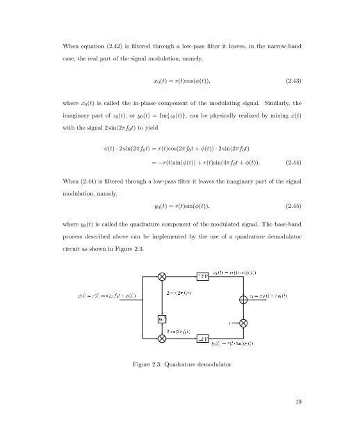
where y 0 (t) is called the quadrature component of the modulated signal. The base-band<br />
process described above can be implemented by the use of a quadrature demodulator<br />
circuit as shown in Figure 2.3.<br />
ܴصִصÓ×´¾¼Ø·´Øµµ<br />
¾Ó×´¾¼Øµ<br />
¼¼<br />
¾×Ò´¾¼Øµ<br />
ÄÈ<br />
ÄÈ<br />
ܼ´ØµÖ´ØµÓ×´´Øµµ<br />
޼ܼ´Øµ·Ý¼´Øµ<br />
<br />
ݼ´ØµÖ´Øµ×Ò´´Øµµ<br />
Figure 2.3: Quadrature demodulator<br />
19