WARNING - Hapero
WARNING - Hapero
WARNING - Hapero

Create successful ePaper yourself
Turn your PDF publications into a flip-book with our unique Google optimized e-Paper software.
PLUG<br />
&<br />
C E R T I F I C A T E<br />
FOR<br />
MECHANISM & SOFTWARE<br />
DESIGN<br />
F I R E<br />
P L U G A N D F I R E . E U<br />
P l u g a n d F i r e Z e r t i f i z i e r t<br />
HAPERO<br />
ENERGIETECHNIK GMBH<br />
Adjustment and instrcution sheet<br />
HP 02 / K (Pellets basement boiler)<br />
HP 02 / W (Pellets living room model)<br />
ALANCE
intelligent technology<br />
All of our products already adhere strictly to the European requirements. It is of our greatest<br />
concern to produce your pellets boilers according to the strict international engineer<br />
standards, but also with the highest quality according to a specialized Quality management.<br />
We attach importance to our final inspection which is carried out by our specialists.<br />
However, if any troubles occur, please do not hesitate to contact your specialist dealer or<br />
fitter. As it is of our most importance to improve every day and avoid mistakes, we would<br />
appreciate informing us about any negative circumstances. Please contact us with your<br />
problem ander the following address:<br />
meldung@speed.at<br />
Plug & Fire<br />
Certified heating appliances guarantee:<br />
Certified heating appliances which do not have to be deconstructed after delivery to get them into your house.<br />
Certified heating appliances which do not have to be build together at the place of delivery.<br />
Certified heating appliances with nearly no effort for wiring.<br />
Certified heating appliances with nearly no effort for initiation.<br />
Certified heating appliances with cable-free controls.<br />
1<br />
PLUG<br />
&<br />
C E R T I F I C A T E<br />
FOR<br />
MECHANISM & SOFTWARE<br />
DESIGN<br />
F I R E<br />
P L U G A N D F I R E . E U<br />
Warning!<br />
Please note that, even with switched-off assets certain performances will still work out. To make sure that<br />
there is absolutely no electricity left, cut your heater from your Power supply.<br />
Please note that you adhere to your general national and international rules and regulations.<br />
Use original spare parts ONLY. Violation makes you lose your guarantee and warranty and moreover affect<br />
your safety and functionality of your device in a negative way.<br />
The owner of the combustion plant or the person entitled to dispose of the combustion plant has to keep<br />
the technical documents in order to hand them over to the authority or the chimney sweeper if required.<br />
HAPERO<br />
ENERGIETECHNIK GMBH<br />
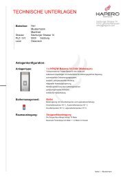
Living room model<br />
Certified ander EN 14785<br />
HAPERO<br />
ENERGIETECHNIK GMBH<br />
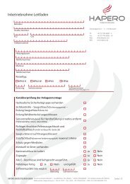
Basement model<br />
Certified ander EN 303-5<br />
HAPERO Balance 2
Please note that you adhere to your general national and international<br />
rules and regulations.<br />
Always carefully read the Adjustment and Instruction sheet before initiating<br />
your pellets boiler.<br />
Regarding transport only use licensed carriers with adequate carrying<br />
capacity for your heater.<br />
Living space model:<br />
When fuel is burned heat energy is released, which can lead to a strong<br />
heating-up of the surface area of the heater, the doors, the glass door,<br />
the boiler tube and the face wall of the heater. Any contact with those<br />
areas is strongly prohibited without adequate aid like heat predection<br />
gloves.<br />
Please check your pellets boilers on damages and completeness<br />
after delivery. Please inform your specialist dealer or fitter about<br />
any shortcomings.<br />
The owner of the combustion plant or the person entitled to dispose<br />
of the combustion plant has to keep the technical documents<br />
in order to hand them over to the authority or the chimney sweeper<br />
if required.<br />
3<br />
Storage room filling<br />
30 minutes before the storage-room filling you have to switchoff<br />
the pellets boiler. You may only begin when the display of<br />
the operating condition shows standby. (see page 17)<br />
1. Important Information<br />
It is important to point the danger out to your children of such a pellets<br />
boiler and keep your children away during the heating.<br />
Do not put any non heat predection objects on your pellets boilers or<br />
nearby.<br />
Do not dry your clothes on your pellets boilers.<br />
Do not place your hat stand near to your pellets boiler. FIRE DANGER!<br />
Do not work with easily flammable or explodeable material in the<br />
same room as your boiler while heating.<br />
Use original spare parts ONLY. Violation makes you lose your guarantee<br />
and warranty and moreover affect your safety and functionality<br />
of your device in a negative way.<br />
The carton and the transparency can easily be put to the municipal waste.<br />
Ash removal<br />
The ash removal is carried out by max 1,000 kg pellets. If the ash tank is overfilled,<br />
you have to consider a loss of efficiency of the pellets boiler. As the ash<br />
cannot be hold in the ash tank anymore, one can assume that, the flue ash<br />
lays down in the chimney or the chimney pipe.<br />
You can read the instructions for the removal of the ash tank of the pellets<br />
boiler at page 53 in the Adjustment and Instruction sheet.<br />
Power blackout – during heating<br />
After a short power blackout the heating adjustments, which the heater had<br />
before the blackout, are continued. If the power blackout lasts longer, the<br />
pellets boiler starts from the beginning again (Cleaning, material supply,<br />
preparation, firing and heating), as long as the temperature demand of the<br />
heater loops, the boilers or puffers fit.<br />
Power blackout – during starting stage<br />
After a power blackout during the starting stage the start activity is repeated.<br />
Overheating<br />
A safety temperature limiter (STL) switches-off the pellets boiler automatically<br />
in case of overheating. However, a overheating can only occur if the<br />
pumps drop out, the water pressure in the boiler declines or the hydraulic<br />
system cables have any errors. Therefore, after the cooling down of the boiler,<br />
you have to push the STL-button per hand to check the pumps in an aggregate<br />
test. Moreover, the water pressure of the boiler and the hydraulic system<br />
cables have to be checked as well.<br />
2. automatic safety function<br />
Fuse<br />
The device is secured with a main fuse (located on the power section in the<br />
inside of the device) in case of a overcurrent. The electric connection has to<br />
be carried out by a specialist only. You have to watch out for the groanding of<br />
the boiler, the hydraulic system cables and the suction hose.<br />
Please note that every change of the electronic system, a change<br />
of the installation, a change of the machine head or a change<br />
of the design is strictly prohibited.<br />
The connection of the boiler to the Power supply, the suction<br />
hose, the holding engine, the heater loops, the boilers and puffers<br />
may only be carried out by specialist.<br />
Violation makes you lose your guarantee and warranty and moreover<br />
affect your safety and functionality of your device in a<br />
negative way.<br />
HAPERO Balance 4
5<br />
table of contents<br />
1. Important information Page 3<br />
2. Automatic safety function Page 4<br />
3. What are wood pellets? Page 7<br />
4. Combustion air Page 7<br />
5. Operating in general Page 8<br />
6. First steps Page 9<br />
7. Cable free room controller Page 10<br />
8. Keyboard functions Page 11<br />
Information menu Page 11 / 13<br />
Removal of the ash tank - change of the viewing glass Page 11 / 49<br />
Time and energy management Page 11 / 19<br />
Parameter menu Page 11 / 27<br />
9. Operation of the menu Page 12<br />
Switch-on Page 12<br />
Switch-off Page 12<br />
Time setting Page 12<br />
Date setting page 12<br />
10. Information menu Page 13<br />
11. Report and fault indication Page 16<br />
For the expert and fitter Page 18<br />
A-1. Brief description of energy management Page 18<br />
A-2. Time and energy management menu Page 19<br />
Energy module Page 19<br />
Days of the week Page 19<br />
Time section Page 19<br />
Parameter heater circuit Page 20<br />
Parameter puffer Page 21<br />
Parameter boiler Page 21<br />
A-3. Standard times and data Page 22<br />
Set up example of heater circuit times and temperature data Page 24<br />
Set up example of pellets charging time and puffer charging temperature Page 25<br />
Set up example of boiler charging time and temperature data Page 26<br />
A-4. Prameter menu Page 27<br />
A-5. Notices for other than the given adjustments Page 28<br />
A-6. Aggregate test Page 29<br />
For the fitter and electrician Page 32<br />
B-1. Installation of the pellets boiler Page 33<br />
Setting up of the chimney connection Page 33<br />
Soil predection for the living room Page 33<br />
Clearance distance Page 34<br />
B-2. Casing of the device Page 35<br />
B-3. Combustion air Page 35<br />
B-4. Room holding (suction hose and return air hose) Page 36<br />
B-5. Module set up Page 37<br />
Allocation Page 37<br />
Set up example Page 37<br />
B-6. Electrical connection Page 38<br />
B-7. Terminal diagram and energy management Page 39<br />
Heater circuit (terminal diagram) Page 39<br />
Puffer (terminal diagram) Page 39<br />
External capacity/external contact (terminal diagram) Page 40<br />
Outside temperature (terminal diagram) Page 40<br />
Boiler (terminal diagram) Page 40<br />
B-8. Terminal diagram power section Page 41<br />
B-9 Safety exchange Page 43<br />
B-10 Air gap switch & operation (dry contact) Page 44<br />
B-11. Initiation guide Page 45<br />
B-12. Plug & Easy Page 47<br />
Service department and fitter Page 52<br />
C-1. Cleaning of the boiler Page 53<br />
C-2. Maintenance of the boiler Page 55<br />
C-3. Check sheet for the maintenance of the boiler Page 58<br />
C-4. Sectional drawing of the boiler Page 58<br />
C-5. Smoke gas travels Page 60<br />
C-6. The burner Page 61<br />
C-7. Electrical components Page 62<br />
Tips for the service department Page 64<br />
Important pages for... Page 63<br />
Heater circuit, where do I get all the information, how do I find the mistakes? Page 66<br />
Room holding Page 68<br />
General information for the room holding Page 69<br />
Build-up instructions for the holding screw Page 70<br />
General Page 76<br />
Spare parts Page 77<br />
Setting up explanation Page 78<br />
CE conformity explanation Page 79<br />
Technical data Page 81<br />
Version reference note<br />
This operating instruction is conform with the following software version<br />
or higher. See page 11.<br />
Errors as well as literal and phrase mistakes excepted, all information without engagement!v<br />
Identification: 1AA Software version: 0018<br />
Identification: C1A Software version: 0005<br />
Legend<br />
Important information Security advice<br />
Practical advice<br />
HAPERO Balance 6
Pellets are manufactured from waste wood which is produced by sawmills<br />
or plane factories as well as demolition wood from a forest enterprise. These<br />
base products are reduced to small pieces, dried and then compressed to pellets<br />
without any help of binding materials.<br />
Specification for high quality pellets::<br />
Data sheet for wood pellets ander Austrian standards M 7135, DIN-51731<br />
standard and SWISSPELLET<br />
Aperture 6 mm<br />
Length 5 - 30 mm (20% - 45 mm)<br />
Surface clogged<br />
Tightness min. 1.12 kg / dm³<br />
Bulk weight min. 650 kg / m³<br />
Energy content min. 4.6 kWh / kg<br />
Humidity ratio max. 10 %<br />
Ash content max. 0,5 %<br />
Dust content max. 1 %<br />
Binding material prohibited<br />
Pollution none<br />
<strong>WARNING</strong>: Before entering the storage space make sure efficient<br />
air vent is given!<br />
When using a holding screw you have to make sure<br />
that NO electrical power is switched-on before entering<br />
the storage space.<br />
Every combustion process needs oxygen or air. The combustion air is usually<br />
detracted from the room.<br />
Self-sufficient ambient-air air supply:<br />
The pellets boiler can be provided by two separate air hoses, not depending<br />
on the ambient air.<br />
Warning: When using the living room model the upper viewing glass cartridge<br />
seal has to be inserted.<br />
Air extraction from the living room:<br />
With the modern accommodations sometimes air cannot flow in enough<br />
through airtight windows and doors. Additional air vent (bathroom or kitchen)<br />
can cause troubles. If there is no possibility to supply external combustion<br />
air, you should ventilate your room several times during a day to assure<br />
good combustion, because bad ventilation can cause low-pressure which<br />
results in bad combustion.<br />
7<br />
3. wood pellets, what is it?<br />
4. Combustion air<br />
The usage of cheap or illegal pellets fuels affects the performance<br />
of your pellets boiler and can furthermore lead to an expiration<br />
of your warranty, guarantee and with it your product<br />
liability. Adhere to the cull burning prohibition!<br />
Pellets storing<br />
To assure a smooth and efficient burning of your pellets, it is essential to<br />
store the burning fuel as dry and pollution free as possible. During the pellets<br />
compress process carbon monoxide is boanded, which is laid off again in the<br />
storage space. Sufficient air vent has to be given in the storage space. Buried<br />
tanks may only be entered after a carbon monoxide measurement.<br />
<strong>WARNING</strong>: Waste materials and fluidity must not be burned in<br />
pellets boiler!<br />
TECHNOLOGY<br />
The technological advance of your pellets boilers results in long lasting test<br />
series in laboratories and practical experience. The practical advantages of<br />
your pellets boiler are convincing.<br />
Types of pellets!<br />
The pellets boiler is able to use different types of pellets as well<br />
as different types of fuels. Page 13 gives you the information<br />
which types can be used.<br />
Air extraction from the boiler room:<br />
Boiler rooms with a pellets boiler have to conform to the national forces ventilation<br />
standards.<br />
Supply of external combustion air (Self-sufficient ambient-air)<br />
Through the outside combustion air there is no need for separate air ventilation<br />
for your accommodation or boiler room, where the pellets boiler is<br />
located.<br />
Initiation may only take place if the device is fully assembled and<br />
the boiler water filled. Violation makes you lose your guarantee and<br />
warranty and moreover affect your safety and functionality of your<br />
device in a negative way.<br />
Is the device used properly, overheating cannot take place. Violation<br />
in the usage of the electrical boiler component parts (compressor,<br />
engine and electrical control) can shorten the life expectancy.<br />
Cable-free room controller<br />
Easy handling with the best comfort possible guarantees a comforting heat<br />
in the whole house.<br />
If you are not using the room controller, time program 1 of the Heater<br />
circuit is used.<br />
Basic references<br />
The pellets boiler is equipped with a modern, programmable microprocessor<br />
control.<br />
The device performances can be adjusted to the user needs at the internal<br />
operating panel, which is located on the left hand upper device casing. Adjustments<br />
or changes at the control and operation board may be carried out<br />
by specialists or skilled service teams only. Violation makes you lose your<br />
guarantee and warranty.<br />
5. Operation in general<br />
The pellets boiler is licensed for pellets burning only, produced ander<br />
the Austrian standards M 7135, DIN-PLUS standard as well as<br />
SWISSPELLET.<br />
The burning of non pressed solid fuel (straw, corn, cull etc.) is prohibited.<br />
Violation makes you lose your guarantee and warranty and moreover<br />
affect your safety and functionality of your device in a negative way.<br />
Control display<br />
HAPERO<br />
ENERGIETECHNIK GMBH<br />
The high intelligent Control-Philosophy in the inside of your <strong>Hapero</strong> pellets<br />
boiler is perfectly balanced. The control display is intended for adjustment<br />
and parameter operations only.<br />
LED number - DISPLAY<br />
The LED-display basically shows the time. The information is shown readable<br />
after a keystroke on the LED display. It is also possible to show other information<br />
permanently on the display.<br />
Status display (green)<br />
The status display (green LED) shows the current condition of your pellets<br />
boilers. If the LED glows, the boiler is switched-on. When switched-off the<br />
LED does not glow. If the pellets screw transports the pellets into the burner,<br />
the status is changing, the LED is blinking.<br />
HAPERO Balance 8
To make the start as easy as possible with our products your pellets boiler is<br />
preprogrammed before delivery.<br />
Before start running your pellets boiler for the first time always check the<br />
installation and correct connection of your pellets boiler with your funnel.<br />
9<br />
Please read the adjustment and instruction sheet carefully before<br />
switching-on the pellets boiler.<br />
6. First steps<br />
MATERIAL FILl<br />
With attached room holding:<br />
With attached room holding there is no further action needed.<br />
Without attached room holding:<br />
If there is no automatic room holding, fill the holding tank with pellets before<br />
initiation. The pellets sensor located in the pellets holding tank has to be covered.<br />
Use a aluminum adhesive foil or switch the parameter menu to “Manual<br />
filling” to 1 (as described on page 27)<br />
SWITCH-ON<br />
To switch-on your pellets boiler press (ARROW) for 3 seconds.<br />
FINISHED!<br />
When heating for the first time with your pellets boiler it might<br />
lead to slight noise and smell nuisance. This process has to be<br />
carried out while the windows are open.<br />
7. the cable-free room controller<br />
The cable-free room controller is one of the most important control elements. All preset temperature data, times and temperature adjustments can be activated<br />
smoothly and convenient. The room controller sends every 20 seconds the adjusted and measured data.<br />
The operating distance covers 30 meters, dependent on the local conditions.<br />
If the operating distance of the room controller is not enough, you can exchange your cable-free model against a cable-boand<br />
model.<br />
Please note that the cable-free room controller is mounted at the correct assembly<br />
stand. Do not mount your room controller next to a source of heat, as<br />
the radiant energy can falsify the data.<br />
Through the thermostat/cryostat you adjust your heat to your desired temperature.<br />
The operation dial helps you to operate the pellets boiler and Heater<br />
circuit very easily.<br />
If you use one or more Heater circuits, the room controller is attached to the<br />
respective Heater circuit.<br />
Up to three cable-free room controller can be attached. Through this attachment<br />
to the Heater circuit the real temperature is measured and the flow<br />
temperature (heater and floor temperature) is rectified.<br />
If the desired temperature is NOT measured correctly from the room controller,<br />
the operation can be switched-off, see page 20 “Room controller operations”.<br />
Please note that the cable-free room controller is not mounted<br />
next to a source of heat.<br />
Operation switcher<br />
AUSGESCHALTET<br />
Conform temperature<br />
ZEITBETRIEB (Time program 1)<br />
(Conform temperature and Savings temperature)<br />
ZEITBETRIEB (Time program 2)<br />
(Conform temperature and Savings temperature)<br />
Savings temperature<br />
WÄRMER / KÄLTER-Regler<br />
(KorrekturInterval from ca. -4° Celsius to ca. +4° Celsius)<br />
Switch-off<br />
With this operation the Heater circuit or the pellets boiler is switched-off. The<br />
anti-freeze predection remains active. (Boiler water 6 ° Celsius)<br />
conform temperature<br />
The temperature is permanently regulated.<br />
time operation 1<br />
This operation regulates the conform temperature and the energy saving<br />
temperature. Within the time window (time program 1) the conform temperature<br />
is regulated, without the time window the energy saving temperature.<br />
Time operation 2<br />
This operation regulates the conform temperature and the energy saving<br />
temperature. Within the time window (time program 2) the conform temperature<br />
is regulated, without the time window the energy saving temperature.<br />
energy saving temperature<br />
The energy saving temperature (reduced time temperature) is permanently<br />
regulated.<br />
HAPERO Balance 10
Room controller<br />
Connection test<br />
3 Seconds<br />
SW-Version<br />
3 Seconds<br />
HW-Version<br />
InforMation menu<br />
8. Keyboard functions<br />
HAPERO<br />
ENERGIETECHNIK GMBH<br />
HAPERO<br />
ENERGIETECHNIK GMBH<br />
Boiler temperature<br />
HAPERO<br />
ENERGIETECHNIK GMBH<br />
In order to change the information<br />
on the display, press the button<br />
with constant pressure.<br />
3 Seconds 3 Seconds<br />
3 Seconds<br />
Nominal temperature<br />
Boilertemperature<br />
ON / OFF Change<br />
3 Seconds<br />
Burning room temp.<br />
Press the buttons and simultaneously for 3 seconds. The display<br />
shows [ -I.P- ]. After the 3 seconds you get to the I-Program level.<br />
Time and energy management menu<br />
Press the buttons ------- and -------- for 3 Seconds. During the holding time<br />
the display shows[ -E.P- ]. After the 3 seconds you get to the E-Program level.<br />
11<br />
(Page 66)<br />
Outside temperature<br />
ON / OFF state<br />
3 Seconds<br />
Operating condition Time within the operating condition<br />
3 Seconds<br />
Change of the Ash tank & viewing glass<br />
HAPERO<br />
ENERGIETECHNIK GMBH<br />
The boiler has to be switched-off and the heating program has to be fnished.<br />
Press the buttons and for 3 seconds. The ventilator runs for 120<br />
seconds. If the boiler should be ready for the change of the viewing glass, the<br />
diesplay shows [ FAIL ].<br />
Parameter menu<br />
HAPERO<br />
ENERGIETECHNIK GMBH<br />
Press the buttons and simultaneously and after two more seconds<br />
additionally the button The display shows [ -P.P- ]. After the 5 seconds<br />
you get to the P-Program level.<br />
If you should have pressed a wrong button or did not press it for 2 seconds<br />
the display shows [ FAIL ].<br />
Switch-on<br />
The display state is shown if the button is pressed shortly.<br />
Press the button for 3 seconds and the pellets boiler is switched-on.<br />
Switch-off<br />
The display state is shown if the button is pressed shortly.<br />
Press the button for 3 seconds and the pellets boiler is switched-off.<br />
time setting<br />
Press the buttons and simultaneously for 3 seconds. The display<br />
shows<br />
Press the button -------- You are now in the programming function, program<br />
code 01. Press the button to get to the time setting.<br />
HOURS<br />
Press in order to raise the hours. Press in order to raise the minutes.<br />
In order to save the adjusted data press to leave the P-Menu.<br />
9. operation of the menu<br />
MINUTES<br />
Date setting<br />
Press the buttons and simultaneously for 3 seconds. The display<br />
shows<br />
You are now in the programming function, program code 00. Press the button<br />
two times in order to get to the program code 02.<br />
You are now in the programming function, program code 02. Press the button<br />
in order to get to the Day/Month setting.<br />
DAY<br />
MONTH<br />
Press the button in order to raise the days. Press the button in order<br />
to raise the month. In order to leave the Day/Month data press<br />
You are now in the program code 02.<br />
Press the button in order to get to the program code 03.<br />
You are now in the programming function, program code 03<br />
Press the button in order to get to Date setting.<br />
Press in order to decrease the date. Press in order to raise the date.<br />
In order to leave and save the date settings press twice. -----<br />
If your pellets boiler is seperated from your Power supply more<br />
than 14 days, your time and date settings have to be adjusted<br />
again. All additional data will stay the same.<br />
HAPERO Balance 12
introduction<br />
10. Information menu<br />
HAPERO<br />
ENERGIETECHNIK GMBH<br />
Press the buttons and simultaneously for 3 seconds. The display<br />
shows [ -I.P- ]. After 3 seconds you get to the I-Program level.<br />
Nr. appellation Information<br />
13<br />
1. Time Time setting<br />
2. Date Date setting (Month, Day)<br />
3. Year Year setting<br />
4. Day of the week Display for the day of the week<br />
Within this menu you can adjust the date and time and furthermore you have<br />
got the information code and the material adjustment. (Chapter material adjustment).<br />
From point 7 you get all the information for your boiler and the energy management.<br />
Press or in order to navigate trough the menu.<br />
In order to get the information from menu point 1 to 9, press .<br />
From point 7 the information is shown automatically. No adjustments are<br />
possible.<br />
The line number as well as the belonging information are listed in the following<br />
schedule.<br />
5. Material quantity Quantity = Percentage of the flow rate (Amount is automatically adjusted if REFA = active, page 27)<br />
6. Typ of pellets 6,0 = 6 mm Aperture of the pellets, 7,0 = Mandelschalen, 8,0 = 8 mm Aperture of the pellets, (Warning, adhere to the Software version )<br />
7. Information code The display shows the information with the keypress inactive<br />
8. Mode Boiler state: Standby = Stby / Preperation = GO 1 / Fire recognition = GO 2 / Scorching stage = burn / Heating = HEAt / Burning out = StOP<br />
9. End-of-heating code 1.0 Flame went out<br />
2.0 End of heating time<br />
3.0 Max temperature achieved<br />
4.0 Pellets used<br />
5.0 Heater was switched-off<br />
6.0 Get pellets if Flex time is finished<br />
7.0 No fire recognition<br />
8.0 Ait was not achieved (air quantity sensor)<br />
9.0 External regulation, Performance below 0.3 Volt<br />
10.0 Temperature standards is 0°<br />
11.0 Temperature drifting in the scorching stage is too low<br />
20.0 The minimum boiler temperature was not achieved<br />
22.0 End-of-heating code trough external contact<br />
77.0 Time expired for scorching stage<br />
90.0 Combustion chamber overfilling<br />
99.0 Screw safety temperature is OK again<br />
10. Boiler heating time active 0 = Outside the boiler heating times // 1 = Insied the boiler heating time<br />
11. Boiler room temperature Room controller (attached to the boiler) measured temperature<br />
12. Boiler room controller address Room controller (attached to the boiler) address (Dip- switch)<br />
13. Boiler room controller mode Room controller (attached to the boiler) switch setting 1 - 5<br />
14. Boiler room controller readjusting Room controller (attached to the boiler) THERMOSTAT/CRYOSTAT<br />
15.<br />
16.<br />
Boiler room controller battery Room controller (attached to the boiler) battery terminal voltage<br />
18. Theoretical performance Current theoretical performance as per power regulator<br />
19. Air performance Current air performance (Preferred)<br />
20. Material performance Current material performance (Retightened)<br />
21. Daytime holding tank file Current available daytime holding tank file<br />
22. Daytime holding tank temperature Daytime holding tank temperature (Safety monitor)<br />
23. Outside temperature Outside temperature<br />
Nr. appellation Information<br />
24. Boiler temperature Boiler temperature<br />
25. Combustion air temperature Combustion air temperature<br />
26. Theoretical LM Air set point<br />
27. LM Data Measured air quantity, indicated value 0 -900,0<br />
28.<br />
33.<br />
Stage blower Blower output value 0 - 120 (0 % to 100 %)<br />
35. Boiler Boilertemperature<br />
36. Boiler charging time basic tempe- 0 = Outside boiler charging time for the basic temperature<br />
rature<br />
1 = Inside boiler charging time for the basic temperature<br />
37. Boiler charging time 0 = Outside boiler charging time<br />
1 = Inside boiler charging time<br />
38.<br />
41.<br />
Boiler legionella charging time 0 = Outised legionella charging time<br />
1 = Inside legionella charging time<br />
40 Puffer higher Puffer temperature higher<br />
41 Puffer lower Puffer temperature lower<br />
42. Puffer solar Solar sensor temperature<br />
43.<br />
46.<br />
49.<br />
Puffer charging time 0 = Outside charging time<br />
1 = Inside charging time<br />
50. Error code last Error code 1<br />
51. Error code next to last Error code 2<br />
52. Error code Error code 3<br />
53. Error code Error code 4<br />
54. Error code Error code 5<br />
55. Error code Error code 6<br />
56. Error code Error code 7<br />
57. Error code Error code 8<br />
58. Error code Error code 9<br />
59.<br />
60.<br />
Error code Error code 10<br />
69.<br />
70. HK1 Heating time active Time frame 1 Time frame 2 0 = Outside heating time // 1 = Inside heating time<br />
71. HK1 VL Theoretical temperature Measured supply temperature<br />
72. HK1 VL Actual temperature Measured supply temperaturer<br />
73. HK1 Theoretical room temperature Adjusted room temperature<br />
74. HK1 Actual temperature Room controller (attached to Heater circuit 1) measured room temperature<br />
75. HK1 Room controller address Room controller (attached to Heater circuit 1) address (Dip-switch)<br />
76. HK1 Room controller mode Room controller (attached to Heater circuit 1) Switch setting 1 - 5<br />
77. HK1 Room controller readjustment Room controller (attached to Heater circuit 1) THERMOSTAT/CRYOSTAT<br />
78. HK1 Room controller battery Room controller (attached to Heater circuit 1) battery terminal voltage<br />
79. HK1 Pump / Mixer = Pump is off = Mixer on Pump is on = Mixer to Pump is on<br />
H e a t e r c i r c u i t 1<br />
HAPERO Balance 14
Nr. Appellation Information<br />
80. HK2 Active heating time Time frame 1 Time frame 2 0 = Outside heating time // 1 = Inside heating time<br />
81. HK2 VL Theoretical temperature Measured supply temperature<br />
82. HK2 VL Actual temperature Measured supply temperature<br />
83. HK2 Theoretical room temperature Adjusted room temperature<br />
84. HK2 Actual room temperature Room controller (attached to Heater circuit 2) measured room temperature<br />
85. HK2 Room controller address Room controller (attached to Heater circuit 2) address (Dip-switch)<br />
86. HK2 Room controller mode Room controller (attached to Heater circuit 2) switch setting 1 - 5<br />
87. HK2 Room controller readjustment Room controller (attached to Heater circuit 2) THERMOSTAT/CRYOSTAT<br />
88. HK2 Room controller battery Room controller (attached to Heater circuit 2) battery terminal voltage<br />
89. HK2 Pump / Mixer = Pump off = Mixer on Pump is on = Mixer to Pump is on<br />
90. HK3 Active heating time Time frame 1 Time frame 2 0 = Outside heating time // 1 = Inside heating time<br />
91. HK3 VL Theoretical temperature Measured supply temperature<br />
92. HK3 VL Actual temperature Measured supply temperature<br />
93. HK3 Theoretical room temperature Measured room temperature<br />
94. HK3 Actual room temperature Room controller (attached to Heater circuit 3) measured room temperature<br />
95. HK3 Room controller address Room controller (attached to Heater circuit 3) address (Dip-switch)<br />
96. HK3 Room controller mode Room controller (attached to Heater circuit 3) switch setting 1 - 5<br />
97. HK3 Room controller readjustment Room controller (attached to Heater circuit 3) THERMOSTAT/CRYOSTAT<br />
98. HK3 Room controller battery Room controller (attached to Heater circuit 3) battery terminal voltage<br />
HK3 Pump/ Mixer = Pump off = Mixer on Pump is on = Mixer to Pump is on<br />
100. Performance 0 Data in hours, Interval 1% - 5% (Single liquidation 3 Seconds, Total liquidation 5 Seconds press)<br />
101. Performance 1 Data in hours, Interval 6% - 15% (Single liquidation 3 Seconds, Total liquidation 5 Seconds press)<br />
102. Performance 2 Data in hours, Interval 16% - 25% (Single liquidation 3 Seconds, Total liquidation 5 Seconds press)<br />
103. Performance 3 Data in hours, Interval 26% - 35% (Single liquidation 3 Seconds, Total liquidation 5 Seconds press)<br />
104. Performance 4 Data in hours, Interval 36% - 45% (Single liquidation 3 Seconds, Total liquidation 5 Seconds press)<br />
105. Performance 5 Data in hours, Interval 46% - 55% (Single liquidation 3 Seconds, Total liquidation 5 Seconds press)<br />
106. Performance 6 Data in hours, Interval 56% - 65% (Single liquidation 3 Seconds, Total liquidation 5 Seconds press)<br />
107. Performance 7 Data in hours, Interval 66% - 75% (Single liquidation 3 Seconds, Total liquidation 5 Seconds press)<br />
108. Performance 8 Data in hours, Interval 76% - 85% (Single liquidation 3 Seconds, Total liquidation 5 Seconds press)<br />
109. Performance 9 Data in hours, Interval 86% - 95% (Single liquidation 3 Seconds, Total liquidation 5 Seconds press)<br />
110. Performance 10 Data in hours, Interval 96% - 100% (Single liquidation 3 Seconds, Total liquidation 5 Seconds press)<br />
111. Screw clock Data x 10,000<br />
All the given data from 1 to 9 (apart from 4 = Weekdays) can be readjusted (see chapter menu operation). From line 10 all the information describe the boiler<br />
state, adjustment value, Heater circuit, boiler and puffer parametrization.<br />
15<br />
H e a t e r c i r c u i t 2<br />
H e a t e r c i r c u i t 3<br />
DISPLAY ERROR CAUSE / REPAIR<br />
E. 01 Drive mistake of the multifunctional<br />
motor (Sensor or motor)<br />
Checking of the motor and the sensor with an aggregate test<br />
The burner has to be checked, the pellets have to be removed!<br />
E. 02 Storage space Refill the storage space, checking of the hoses if they are blocked<br />
E. 04 No ignition Remove pellets from the burner, check the fire starter<br />
The burner has to be checked, the pellets have to be removed!<br />
E. 05 No ignition (chimney draft is too high) Remove pellets from the burner, check chimney draft (adjust or attach a chimney draft controller)<br />
The burner has to be checked, the pellets have to be removed!<br />
E. 06 LM data ander the minimum, no air flow Checking of the smoke gas stroke<br />
The burner has to be checked, the pellets have to be removed!<br />
E. 07 LM data ander 70 % for 180 Seconds Checking of the smoke gas stroke, checking of the ash tank<br />
The burner has to be checked, the pellets have to be removed!<br />
E. 08 Cable break, error of the air flow sensor<br />
or sensor<br />
Checking of the air flow sensor with an aggregate test (cable break, defect plug connector, defect air flow senosr)<br />
E. 10 Overfilled burner Cleaning of the burner butterfly valve and checking of the impermeability, check the pull-springs of the burner<br />
butterfly valve, check the flue gas tract. Check the redary drive of the burner butterfly valve.<br />
The burner has to be checked, the pellets have to be removed!<br />
E. 20 Minimum boiler temperature has not<br />
been achieved<br />
E. 50 Sensor break of the combustion space<br />
temperature<br />
Checking of the cables and sensor<br />
E. 51 Sensor break of the boiler temperature Checking of the cables and sensor<br />
E. 80 Decline of the STB Checking of the hydraulic system<br />
E. 98 Temperature monitoring of the pellets<br />
holding tank<br />
E. 99 Screw safety temperature<br />
Bi-Metal<br />
RE-initialisation<br />
Please correct the cause of error trigger, do not hesitate to ask your fitter or<br />
after sale service.<br />
Switch-on the boiler again, everything runs smoothly again.<br />
Information of the display<br />
Checking of the ash tank and air ways:<br />
Die display shows [ASCH] if a certain amount of pellets<br />
have been burned. Please empty the ash tank<br />
(see page 53). This is an information for you and no<br />
error message.<br />
11. Report and fault indication<br />
Checking of the hydraulic system (Gravitaion brake), new balancing of the external adjustment control. The boiler<br />
temperature was ander 55 ° C for one hour.<br />
Removal of the ash tank. Informing of the customer service!<br />
Checking of the daytime holding tank, the burner butterfly valve and the burning chamber!<br />
Contact customer service<br />
HAPERO Balance 16
A-1. Brief description energy-management<br />
Boiler WITHOUT Heater circuit, WITHOUT puffer, WITHOUT room controller,<br />
WITHOUT outside heat sensor<br />
After the boiler is switched-on the boiler starts with 73° Celsius (164.3 fahrenheit).<br />
Boiler WITHOUT Heater circuit, WITHOUT puffer, WITHOUT room controller,<br />
WITHOUT outside heat sensor<br />
After the boiler is switched-on the boiler starts with an adjusted temperature<br />
regulated by the Heater circuit 1.<br />
Boiler WITHOUT Heater circuit, WITHOUT puffer, WITHOUT room controller,<br />
WITHOUT outside heat sensor<br />
After the boiler is switched-on the boiler starts with an adjusted temperature<br />
regulated by the Heater circuit 1. The correction of the boiler temperature is<br />
regulated by the room controller. <strong>WARNING</strong>! The room controller has to be<br />
switched-on for heating. The boiler temperature can be reduced over time<br />
by the room controller.<br />
Boiler WITH Heater circuit, WITH puffer, WITH room controller, WITH<br />
outside heat sensor<br />
After the boiler is switched-on the boiler starts with a temperature calculated<br />
by the Heater circuit or puffer. To optimize the energy consumption one<br />
chooses the temperature which is necessary to power the Heater circuits.<br />
17<br />
A room controller attached to a Heater circuit rectifies the flow temperature<br />
and the boiler temperature as well.<br />
Boiler management<br />
After the connection of the boiler sensor the boiling management is active.<br />
The filling of the boiler takes place after the charging time or rather a surplus<br />
of energy during the heating.<br />
Boiler WITHOUT management, external contact (external adjustment<br />
control)<br />
After the boiler is switched-on the boiler starts with a temperature of 80 °<br />
Celsius (176 Fahrenheit) if the contact is closed. If the contact is opened, the<br />
heating is shut down. (Hydraulic switch is compulsory)<br />
Boiler WITHOUT management, external 0-10 V (external adjustment<br />
control)<br />
The boiler starts with a performance standard according to the voltage input.<br />
Time program<br />
Time program<br />
Time program<br />
Time program<br />
Time program<br />
Time program<br />
A-2. Time and energy management menu<br />
Introduction<br />
HAPERO<br />
ENERGIETECHNIK GMBH<br />
Press the buttons and for 3 seconds. During the charging time<br />
the display shows [ -E.P- ]. After the 3 seconds you get to the E-Program level.<br />
energy modules<br />
19<br />
Boiler times: Inside the time frame the boiler is<br />
ready for heating, outside the time frame no heating<br />
takes place.<br />
Heater circuit time 1 from Heater circuit 1: Inside<br />
the time frame heating takes place at conform<br />
temperature, outside with energy saving temp.<br />
Heater circuit time 2 from Heater circuit 1: Inside<br />
the time frame heating takes place at conform<br />
temperature, outside with energy saving temp.<br />
Heater circuit time 1 from Heater circuit 2: Inside<br />
the time frame heating takes place at conform<br />
temperature, outside with energy saving temp.<br />
Heater circuit time 2 from Heater circuit 2: Inside<br />
the time frame heating takes place at conform<br />
temperature, outside with energy saving temp.<br />
Heater circuit time 1 from Heater circuit 3: Inside<br />
the time frame heating takes place at conform<br />
temperature, outside with energy saving temp.<br />
Heater circuit time 2 from Heater circuit 3: Inside<br />
the time frame heating takes place at conform<br />
temperature, outside with energy saving temp.<br />
Puffer charging times: Inside the time frame the<br />
puffer is checked for the adjusted temperature, if<br />
needed, the puffer gets loaded.<br />
Boiler charging times: Inside the time frame the<br />
boiler is checked for the adjusted temperature, if needed,<br />
the boiler gets loaded.<br />
Boiler basic temperature time: Inside the time<br />
frame the boiler must not fall ander the basic temperature,<br />
if needed, the boiler gets loaded.<br />
Legionella charging time: Inside the time frame<br />
the boiler gets heatet at legionella temperature.<br />
<strong>WARNING</strong>: Danger of scalding!<br />
Filling of the pellets and cleaning times: Inside<br />
the time frame you may refill the pellets as you demand.<br />
Time frame for Relay 8: Inside the time frame relay<br />
8 adjustment 10 the potential-free contact gets<br />
pulsed. (See page 44).<br />
Within this menu you can ajdust all time frames and heater circuit parameter<br />
as well as conform temperature, energy savings temperature, outside temperature<br />
mode et cetera. but also all puffer and boiler charging times.<br />
Press ----- or ----- in order to navigate through the energy module. Press<br />
----- in order to get to the submenu.<br />
For configuration examples see page 24.<br />
Without an active room controller time program 1 is<br />
used for the heater circuit.<br />
Weekdays<br />
Monday:<br />
Press ------ in order to adjust the time to the attached<br />
weekday.<br />
Tuesday:<br />
Press ------ in order to adjust the time to the attached<br />
weekday.<br />
Wednesday:<br />
Press ------ in order to adjust the time to the attached<br />
weekday.<br />
Thursday:<br />
Press ------ in order to adjust the time to the attached<br />
weekday.<br />
Friday:<br />
Press ------ in order to adjust the time to the attached<br />
weekday.<br />
Saturday:<br />
Press ----- - in order to adjust the time to the<br />
attached weekday.<br />
Sanday:<br />
Press ------ in order to adjust the time to the attached<br />
weekday.<br />
Parameter:<br />
Press ----- in order to adjust the paramter as well as<br />
the temperature and data.<br />
Time level<br />
Time level 1 From:<br />
Time adjustment for the chosen energy-model as<br />
well as the chosen weekday.<br />
Time level 1 TO:<br />
Time adjustment for the chosen energy-model as<br />
well as the chosen weekday.<br />
Time level 2 From:<br />
Time adjustment for the chosen energy-model as<br />
well as the chosen weekday.<br />
Time level 2 TO:<br />
Time adjustment for the chosen energy-model as<br />
well as the chosen weekday.<br />
HOURS<br />
Time setting<br />
MINUTES<br />
Press ----- to get to the hours. Press ----- to raise the minutes.<br />
Copy function: If you wish to use the time for all weekdays, press for<br />
2 seconds. In order to leave the time setting press ----- .<br />
Parameter Heater circuit<br />
Module:<br />
With this mode you can switch-on or switch-off the<br />
heater circuit.<br />
0.0 = No operation<br />
1.0 = Automatic operation<br />
2.0 = Fixed temperature (Room<br />
temp. is supply temp.)<br />
3.0 = Manual operation (Pump<br />
management only)<br />
Conform temperature:<br />
The conform temperature is the desired pleasent<br />
temperature.<br />
Energy saving temperature:<br />
The energy saving temperature is the temperature,<br />
which is desired outside the heating time.<br />
Room controller address:<br />
The cable-free room controller can adjust to 0 to 7<br />
addresses. The address is necessary in order to get the<br />
right information for the heater circuit.<br />
Address 0.0 Address 1.0 Address 2.0<br />
Address 3.0 Address 4.0 Address 5.0<br />
Address 6.0 Address 7.0<br />
After opening the cable-free room controlleryou<br />
see the DIP - Switching block. You can adjust the<br />
address from 0 to 7.<br />
Check the room controller operations as<br />
explained on page 66.<br />
DIP switcher<br />
Battery AAA<br />
Vent butt strap<br />
In order to open the strap press a screwdriver against it.<br />
Supply temp.<br />
MINUS<br />
55°<br />
Measured supply temperature<br />
46°<br />
Supply temp.<br />
PLUS<br />
23°<br />
k<br />
m<br />
Room controller operation:<br />
Within this operation you can adjust the scope of operation<br />
of the room controller.<br />
1.0 = Total scope of operation<br />
0.0 = The room temperature is not<br />
measured (no main room)<br />
Outside temperature leaded heater circuit-<br />
Switch-off:<br />
If the outside temperature exceeds the adjusted temperature<br />
the heater circuit automatically switches in<br />
the summer operation (no heating).<br />
Outside temp. leaded heater circuit-Switch-on:<br />
If the outside temperature andercuts the adjusted<br />
temperature the heater circuit automatically switches<br />
in the winter operaion (Heating).<br />
Supply temperature leaded heater circuit-<br />
Switch-off:<br />
If the outside temperature andercuts the measured<br />
supply temperature the heater circuit automaticallyswitches<br />
in the summer operation (no hetaing). If a<br />
device test is made in the summer, the outside temperature<br />
sensor has to be unplugged. (Performance part<br />
X17); Thus an outside temperature of -10 ° C is adjusted.<br />
Outside temperature MINUS:<br />
The outside temperature data used is measured by<br />
the outside temperature curve.<br />
Supply temperature MINUS:<br />
The supply data used is measured by the outside<br />
temperature curve.<br />
Outside temperature PLUS:<br />
The outside temperature data used is measured by<br />
the outside temperature curve.<br />
Supply temperature PLUS:<br />
The supply data used is measured by the outside<br />
temperature curve.<br />
Outside temperature curve<br />
Current outside temperature<br />
-15° + 20°<br />
-5°<br />
<br />
k<br />
l<br />
m<br />
Measured<br />
supply temperature<br />
l<br />
Outside temp. MINUS Outside temp. PLUS<br />
The measured supply temperature of 46° C of your heater or floor hetaing<br />
at -5° C outside temperature.<br />
Supply boand (MAX supply temperature):<br />
The max supply temperature of your heater circuits.<br />
Minimal supply temperature:<br />
The measured supply temperature must not andercut<br />
the adjusted data.<br />
Supply room temperature multiplicator:<br />
The temperature data, which is necessary to raise the<br />
temperature by 1 ° C.<br />
Room temperature GSM module:<br />
When activating the X25 contact the current temperature<br />
is used as room temperature.<br />
HAPERO Balance 20
21<br />
Parameter Puffer Parameter Boiler<br />
Active puffer:<br />
0.0 = If the energy is used for the heater circuit, the<br />
puffer does not get loaded. (For example: Solar puffer<br />
during transition time), if the boiler should get<br />
loaded, the puffer filling happens trough the pellets<br />
boiler.<br />
1.0 = Total function<br />
Room temperature heater circuit pump STOP:<br />
1.0 = The heater circuit pump is running during the<br />
winter operation all the time.<br />
0.0 = If the measured room temperature should be<br />
heightened and the adjusted room temperature exceeded<br />
the heater circuit pump is stopped.<br />
Puffer SWITCH-ON-Temperature:<br />
If the adjusted data is shortcutted (measured with<br />
the upper puffer sensor) the puffer gets filled till the<br />
Switch-off temperature.<br />
Energiesparpuffer: The switch-on temperature<br />
should be relatively low, because<br />
the heater circuit adjusts<br />
the switch-on temperature by<br />
its own. With the switch-on<br />
temperature the self adjusted<br />
temperature gets lowered<br />
additionally.<br />
Standardpuffer: Only this temperature is taken<br />
as the switch-on temperature.<br />
Puffer SWITCH-OFF-Temperature:<br />
If the adjusted data is exceeded (measured with the<br />
lower puffer sensor) the puffer filling is stopped.<br />
Warning: Even after the switch-off residual heat can<br />
be used.<br />
If the switch-off temperature is still not reached, but<br />
the boiler is stopped due to cleaning or pellets refilling,<br />
the puffer filling only starts after the switch-on<br />
temperature is shortcutted.<br />
Puffer solar hysteresis:<br />
When using the 3rd sensor (Solar sensor = PT 1000)<br />
the solar pump is activated when the switching temperature<br />
is exceeded.<br />
Switching temperature = the temperature on the lower<br />
puffer sensor + (the adjusted puffer solar hysteresis).<br />
As long as the solar module temperature is higher than<br />
the switching temperature, the solar pump is running.<br />
Puffer model:<br />
Data 7.0 = Energy saving puffer<br />
Data 8.0 = Standard puffer<br />
Data 9.0 = Performance puffer<br />
Active boiler:<br />
0.0 = Boiler filling is not active<br />
1.0 = Boiler filling is active<br />
Boiler SWITCH-ON-Temperature:<br />
If the adjusted data is shortcutted the boiler filling is<br />
activated.<br />
Boiler SWITCH-OF-Temperature:<br />
If the adjusted data is exceeded the puffer filling is<br />
stopped.<br />
Warning: Even after the switch-off residual heat can<br />
be used.<br />
Also if no refilling is required it is possible that during<br />
the heating residual heat comes up and therefore the<br />
boiler filling starts to happen.<br />
Boiler BASIC-Temperature:<br />
When the adjusted data is shortcutted the boiler<br />
filling only takes place till the boiler switch-on<br />
temperature in the winter and the boiler switch-off<br />
temperauter in the summer. As this only happens in<br />
the active time frame of energy model 06 outside<br />
the boiler charging time (Energy model 05) you have<br />
warm water.<br />
Boiler Legionella-Temperature:<br />
During the time frame (Energy model 07) the gets<br />
heated to the adjusted temperature.<br />
Warning: Danger of scalding!<br />
Boiler operation:<br />
Data 1.0 = Boiler gets loaded even if<br />
he is switched-off.<br />
Data 0.0 = No boiler filling takes place.<br />
Boiler with Solar:<br />
Data 0.0 = No Solar boiler operation<br />
Data 1.0 = Solar boiler operation on<br />
the expansion band 1<br />
Data 2.0 = Solar boiler operation on<br />
the expansion band 2<br />
Data 3.0 = Solar boiler operation on<br />
the expansion band 3<br />
This operation is only possible if no configured expansion<br />
band.<br />
Boiler Solar hysteresis:<br />
When using the solar sensor (PT 1000) the solar pump<br />
gets activated if the switching temperature is exceeded.<br />
Switching temperature = the boiler temperature (or<br />
the measured temperature at the lower puffer sensor)<br />
+ the measured boiler solar hysteresis.<br />
As long as the solar model temperature is higher then<br />
the switching temperature the solar pump is running.<br />
<strong>WARNING</strong>:<br />
After the heating of the boiler to legionella temperature the<br />
industrial water can scald. Please adjust your water tap to he<br />
increased water temperature.<br />
A-3. StandardZeiten and -Datae (Werkseinstellung)<br />
Boiler operation time<br />
Weekday Time frame 1 Time frame 2<br />
Monday 00:00 to 12:00 12:00 to 24:00<br />
Tuesday 00:00 to 12:00 12:00 to 24:00<br />
Wednesday 00:00 to 12:00 12:00 to 24:00<br />
Thursday 00:00 to 12:00 12:00 to 24:00<br />
Friday 00:00 to 12:00 12:00 to 24:00<br />
Saturday 00:00 to 12:00 12:00 to 24:00<br />
Sanday 00:00 to 12:00 12:00 to 24:00<br />
Heater circuit-week program 1<br />
Weekday Time frame 1 Time frame 2<br />
Monday 06:00 to 12:00 12:00 to 22:00<br />
Tuesday 06:00 to 12:00 12:00 to 22:00<br />
Wednesday 06:00 to 12:00 12:00 to 22:00<br />
Thursday 06:00 to 12:00 12:00 to 22:00<br />
Friday 06:00 to 12:00 12:00 to 23:00<br />
Saturday 06:00 to 12:00 12:00 to 23:00<br />
Sanday 07:00 to 12:00 12:00 to 22:00<br />
Heater circuit-week program 2<br />
Weekday Time frame 1 Time frame 2<br />
Monday 06:00 to 08:00 16:00 to 21:00<br />
Tuesday 06:00 to 08:00 16:00 to 21:00<br />
Wednesday 06:00 to 08:00 16:00 to 21:00<br />
Thursday 06:00 to 08:00 16:00 to 21:00<br />
Friday 06:00 to 08:00 16:00 to 21:00<br />
Saturday 06:00 to 12:00 12:00 to 22:00<br />
Sanday 07:00 to 12:00 12:00 to 21:00<br />
Puffer charging times<br />
Weekday Time frame 1 Time frame 2<br />
Monday 00:00 to 12:00 12:00 to 24:00<br />
Tuesday 00:00 to 12:00 12:00 to 24:00<br />
Wednesday 00:00 to 12:00 12:00 to 24:00<br />
Thursday 00:00 to 12:00 12:00 to 24:00<br />
Friday 00:00 to 12:00 12:00 to 24:00<br />
Saturday 00:00 to 12:00 12:00 to 24:00<br />
Sanday 00:00 to 12:00 12:00 to 24:00<br />
Boiler charging times<br />
Weekday Time frame 1 Time frame 2<br />
Monday 05:00 to 09:00 17:00 to 21:00<br />
Tuesday 05:00 to 09:00 17:00 to 21:00<br />
Wednesday 05:00 to 09:00 17:00 to 21:00<br />
Thursday 05:00 to 09:00 17:00 to 21:00<br />
Friday 05:00 to 09:00 17:00 to 21:00<br />
Saturday 05:00 to 09:00 17:00 to 21:00<br />
Sanday 05:00 to 09:00 17:00 to 21:00<br />
Solar boiler times:<br />
With the P-Program you can adjust the boiler charging times over the line 61<br />
of the boiler charging times. Press ---- in order to use the times described<br />
below, ----- in order to use the times described above.<br />
Weekday Time frame 1 Time frame 2<br />
Monday - Friday 11:00 to 12:00 17:00 to 21:00<br />
Saturday - Sanday 11:00 to 12:00 17:00 to 21:00<br />
Boiler basic temperature<br />
Weekday Time frame 1<br />
Monday 05:00 to 23:00<br />
Tuesday 05:00 to 23:00<br />
Wednesday 05:00 to 23:00<br />
Thursday 05:00 to 23:00<br />
Friday 05:00 to 23:00<br />
Saturday 05:00 to 23:00<br />
Sanday 05:00 to 23:00<br />
Boiler Legionella charging time<br />
Weekday Time frame 1<br />
Monday 00:00 to 00:00<br />
Tuesday 00:00 to 00:00<br />
Wednesday 00:00 to 00:00<br />
Thursday 00:00 to 00:00<br />
Friday 00:00 to 00:00<br />
Saturday 00:00 to 00:00<br />
Sanday 00:00 to 00:00<br />
Pellets filling and cleaning times<br />
Weekday Time frame 1<br />
Monday 08:00 to 20:00<br />
Tuesday 08:00 to 20:00<br />
Wednesday 08:00 to 20:00<br />
Thursday 08:00 to 20:00<br />
Friday 08:00 to 20:00<br />
Saturday 08:00 to 20:00<br />
Sanday 08:00 to 20:00<br />
HAPERO Balance 22
Heater circuit in general<br />
Parameter Data<br />
Modus 1.0<br />
Conform temperature 22.0<br />
Savings temperature 20.0<br />
Raumregleraddress 1.0 oder 2.0 oder 3.0<br />
RaumreglerFunction 1.0<br />
Outside temperaturegeführte Heater circuit-Switch-off 23.0<br />
Outside temperaturegeführte Heater circuit-Switch-on 18.0<br />
Minimal Supply temperature 0.0<br />
Heater circuit floor heating<br />
Parameter Data<br />
Supply temperature guided heater circuit-switch-off 23.0<br />
Outside temperature MINUS -15.0<br />
Supply temperature MINUS 45.0<br />
Outside temperature PLUS +20.0<br />
Supply temperature PLUS 20.0<br />
Supply boand (max supply temperature) 50.0<br />
Supply room temperature multiplicator 2.0<br />
Heater circuit Radiators 55 / 45<br />
Parameter Data<br />
Supply temperature guided heater circuit-Switch off 23.0<br />
Outside temperature MINUS -15.0<br />
Supply temperature MINUS 55.0<br />
Outside temperature PLUS +20.0<br />
Supply temperature PLUS 30.0<br />
Supply boand (max supply temperature) 70.0<br />
Supply room temperature multiplicator 4.0<br />
Heater circuit Radiators 75 / 55<br />
Parameter Data<br />
Supply temperature guided heater circuit-switch-off 23.0<br />
Outside temperature MINUS -15.0<br />
Supply temperature MINUS 70.0<br />
Outside temperature PLUS +20.0<br />
Supply temperature PLUS 35.0<br />
Supply boand (max supply temperature) 80.0<br />
Supply room temperature multiplicator 4.5<br />
23<br />
Heater circuit panel heating<br />
Parameter Data<br />
Supply temperaturegeführte Heater circuit-Abschaltung 23.0<br />
Outside temperature MINUS -15.0<br />
Supply temperature MINUS 45.0<br />
Outside temperature PLUS +20.0<br />
Supply temperature PLUS 30.0<br />
Supply boand (Max VL-Temperatur) 50.0<br />
Supply room temperature Multiplikator 2.0<br />
Energy saving Puffer data<br />
Parameter Data<br />
Switch-on temperatre 25.0<br />
Switch-off temperature 55.0<br />
Hysteresis (Difference „Lower puffer temperature“solar sensor) 7.0<br />
Standard Puffer data<br />
Parameter Data<br />
Switch-on temperature 60.0<br />
Switch-off temperature 75.0<br />
Hysteresis (Difference „Lower puffer temperature“solar sensor) 7.0<br />
Boiler Data<br />
Parameter Data<br />
Boiler active 1.0<br />
Switch-on temperature 45.0<br />
Switch-off temperature 60.0<br />
Basic temperature 35.0<br />
Legionella temperature 70.0<br />
Boiler operation 1.0<br />
Hysteresis (Difference „Boiler temperature“ solar sensor) 7.0<br />
Abstract boiler parameter<br />
Parameter Data<br />
Max heating time (Minutes) 360.0<br />
Boiler max temperature (Celsius) 83.0<br />
Boiler circuit pump ON (Celsius) 55.0<br />
Max pellets transport time (Minutes) 25.0<br />
Heat exchanger - Cleaning time (Minutes) 3.0<br />
Display Code (Time) 2.0<br />
Max performance (Percentage) 100.0<br />
Minimal performance (Percentage) (about 10 % from<br />
actual performance)<br />
1.0<br />
Intervall of the rust cleaning (Minute) 60.0<br />
Example heating time<br />
You want to change the heater circuit 1 and the heating time from the time<br />
program 1, at Tuesday from 06:00 o‘clock to 07:30 o‘clock.<br />
Time operation (Time program 1)<br />
(Conform temperature and savings<br />
temperature)<br />
HAPERO<br />
ENERGIETECHNIK GMBH<br />
Press ----- and ----- for 3 seconds. During the waiting time the display<br />
shows [ -E.P- ]. After the 3 seconds you get to the E-Program level.<br />
Press ----- t and the wished module is shown. In your case [HC.II]<br />
Heater circuit 1<br />
Time program 1<br />
Press ----- inin order to get to the weekday adjustments.<br />
Press ----- and the wished weekday is shown. In your case [tUE.] (Tuesday)<br />
Press ----- in order to get to the time frame.<br />
Press ----- in order to get to the time display.<br />
Hours<br />
Minutes<br />
Press ----- in order to raise the hours. Press ----- in order to raise the minutes.<br />
If you want to leave the time adjustment press ----- (Time frame),<br />
----- (Weekday),----- (Module),----- (Ende).<br />
When leaving the menu you can easily switch to other menus too.<br />
Example Declining temperature<br />
You want to change the savings temperature from 20,0° C to 18,5° C.<br />
HAPERO<br />
ENERGIETECHNIK GMBH<br />
Press ----- and ----- for 3 seconds. During the waiting time the display<br />
shows [ -E.P- ]. After the 3 seconds you get to the E-Program level.<br />
Press ----- and the wished module is shown. In your case [HC.I.I] or [HC.I.2]<br />
Heater circuit 1<br />
oder<br />
Press ----- in order to get to the weekday adjustments.<br />
Press ----- or ----- and the wished menu is shown. In your case [Para] (for<br />
parameter menu)<br />
Press ----- and the parameter menu is shown.<br />
Press ----- and the wished menu is shown. In your case [Lt.= ] (for savings<br />
temperature)<br />
Press ----- in order to get to the data display.<br />
- 0,1° C<br />
+ 0,1° C<br />
Press ----- in order to lower the temperature. Press ----- in order to raise<br />
the temperature. In order to leave the time setting press ----- (Parametermenü),<br />
----- (Weekday),----- (Module),----- -- (End).<br />
When leaving the menu you can easily switch to other menus too.<br />
HAPERO Balance 24
Example Pellets charging time<br />
You want to change the end time and the pellets flling time and cleaning<br />
time at Wednesday from 20:00 o‘clock auf 19:30 o‘clock.<br />
HAPERO<br />
ENERGIETECHNIK GMBH<br />
Press ----- and ----- for 3 seconds. During the waiting time the display<br />
shows [ -E.P- ]. After the 3 seconds you get to the E-Program level.<br />
Press ----- and the wished module is shown. In your case [E.=08]<br />
Press ----- and you get to the weekday setting.<br />
Press ----- and the wsihed weekday is shown. In Ihrem Fall [UEd.] (für Wednesday)<br />
Press ----- in order to get to the time frame.<br />
Press ----- in order to get to the time frame.<br />
Press ----- in order to get to the time display.<br />
Hours<br />
Minutes<br />
Press ----- in order to raise the hours. Press ----- in order to raise the<br />
minutes. In order to leave the time setting press ----- (Time frame), -----<br />
(Weekday),----- (Module),----- (End).<br />
When leaving the menu you can easily switch to other menus too.<br />
25<br />
Example puffer temperature<br />
You want change the switch-off temperature from 50,0° C auf 60,5° C.<br />
HAPERO<br />
ENERGIETECHNIK GMBH<br />
Press ----- and ----- for 3 seconds. During the waiting time the display<br />
shows [ -E.P- ]. After the 3 seconds you get to the E-Program level.<br />
Press ----- and the wished module is shown. In your case [E.=04]<br />
Press ----- in order to get to the weekday setting.<br />
Press ----- or ----- and the wished menu is shown. In your case [Para]<br />
(Parameter menu)<br />
Press ----- in order to get to the parameter menu.<br />
Press ----- and the wished menu is shown. In your case [P .Ht ] (for Switchoff<br />
temperature)<br />
Press ----- in order to get to the data display.<br />
- 0,1° C<br />
+ 0,1° C<br />
Press ----- in order to lower the temperature. Press ----- in order to raise<br />
the temperature. In order to leave the time setting press ----- (Parametermenü),<br />
----- (Weekday),----- (Modul),----- -- (End).<br />
When leaving the menu you can easily switch to other menus too.<br />
Example boiler charging time Example boiler tgemperature<br />
You want to change the end time 2 from the boiler charging time at Thursday<br />
from 21:00 o‘clock to 22:30 o‘clock.<br />
HAPERO<br />
ENERGIETECHNIK GMBH<br />
Press ----- and ----- for 3 seconds. During the waiting time the display<br />
shows [ -E.P- ]. After the 3 seconds you get to the E-Program level.<br />
Press ----- and the wished module is shown. In your case [E.=05]<br />
Press ----- in order to get to the weekday setting.<br />
Press ----- and the wished weekday is shown. In your case [thu.] (Thursday)<br />
Press ----- in order to get to the time frame.<br />
Press ----- in to get to the time frame.<br />
Press ----- in order to get to the time display.<br />
Hours<br />
Minutes<br />
Press ----- in order to raise the hours. Press ----- in order to raise the<br />
minutes. In order to leave the time setting press ----- (Time frame), -----<br />
(Weekday),----- (Module),----- (End).<br />
When leaving the menu you can easily switch to other menus too.<br />
You want to change the switch-on temperature from 45,0° C auf 50,0° C.<br />
HAPERO<br />
ENERGIETECHNIK GMBH<br />
Press ----- and ----- for 3 seconds. Dring the waiting time the display shows<br />
[ -E.P- ]. After the 3 seconds you get to the E-Program level.<br />
Press ----- and the wished module is shown. In your case [E.=05]<br />
Press ----- in order to get to the weekday setting.<br />
Press ----- or ----- and you get to the wished menu is shown. In your case<br />
[Para] (for parameter menu)<br />
Press ----- in order to get to the parameter menu.<br />
Press ----- and the wished menu is shown. In your case [P .Ht ] (Switch-on<br />
temperature)<br />
Press ----- in order to get to the data display.<br />
- 0,1° C<br />
+ 0,1° C<br />
Press ----- in order to lower the temperature. Press ----- in order to raise<br />
the temperature. In order to leave the time setting perss ----- (Parametermenu),<br />
----- (Weekday),----- (Module),----- (End).<br />
When leaving the menu you can easily switch to other menus too.<br />
HAPERO Balance 26
Einstieg<br />
A-4. ParameterMenü<br />
HAPERO<br />
ENERGIETECHNIK GMBH<br />
Press -------- and --------simultaneously. After 2 seconds press additionally<br />
-------- . The display shows [ -P.P- ]. After the 5 seconds you get to the P-<br />
Program level.<br />
If you have pressed the wrong button or haven‘t waited the 2 seconds the<br />
display sows [ FAIL ].<br />
27<br />
Nr. appellation Information<br />
1 Manual filling 0.0 = automatic room holding / 1.0 = manual filling<br />
2 Message „ASH“ Data * 1000 from which pellets amounts the message „ASH“ (removal of the ash tank) comes up<br />
3 Pulse pellets boiler Pulse amount in the holidng tank per day<br />
4 Room holding handling time Data in seconds - Handling time before the beginning of the holding motor<br />
5 Room holding overtravel time Data in seconds - Overtravel time of the suction turbine after the holding motor stops<br />
6 Room holding Operating time Data in seconds - Operating time während der Holding stage<br />
7 Room holding Dwell time Data in seconds - Dwell time während der Holding stage<br />
8 Room holding transport time Data in minutes - Max time till cognition of the material off ( Error code 02)<br />
9 Chimney flue barrier active 0.0 = The chimney flue barrier acitve is not activated in the night (no rattle noise) / 1.0 = The barrier is also carried out in the night<br />
10 Aggregate test The description is in the chapter aggregate test page 29<br />
12 Boiler circuit pump Data in Celsius - Switching temperature in the boiler circuit pump<br />
13 Max heating time Data in Minutes - Max heating time to Burner cleaning<br />
14 Boiler actual temperature Data in Celsius - Boiler actual temperature without energy management and outdoor sensor<br />
15 Switch-off temperature Data in Celsius - If the boiler temperature exceeds the switch-off temperature the boiler ends the heating progress<br />
16 Minimal performance Data in Percent - Min heating performance (about. 30 % from the nominal load)<br />
17 Maximal performance Data in Percent - Max heating performance<br />
18 HE-Cleaning time Data in Minutes - Heat exchanger-cleaning time (Multi operation motor)<br />
19 Room controller address „boiler“ Adjustment of the room controller address for the communication between the cable free room controller and the boiler without energy manag.<br />
21 Air adjustment Data in Percent - Data from calibration of the air amount sensor<br />
22 REFA active 1.0 = REFA active / 0.0 = REFA not acitve<br />
23 Max.combustion chamber temp. 80% Max Combustion chamber temperature für REFA at 80 % Heater performance<br />
24 Max.combustion chamber temp.100% Max Combustion chamber temperature für REFA at 100 % Heater performance<br />
25 Burner Prefilltime Data in Seconds - fill to the burner<br />
26 Insertion time primer cognition Data in Seconds - Pulse pauses for the pellets insertion during the scorching time<br />
27 Air amount primer cognition Data in Points - Air amount sensor during the scorching time<br />
28 Primer cognition Data in Celsius - Either scorching rising cognition or the Combustion chamber temperature<br />
29 Max Pulses Max pulse amount at scorching stage<br />
30 Flame off Data in Celsius - When the combustion chamber temperature is shortcutted the flame is recognized as off<br />
31 Scorching stage time 1 Data in Seconds - Time for the first scorching stage<br />
32 Scorching stage 1 performance 1 Data in Percent - Air performance and transport performance/4 during the first scorching time<br />
<strong>WARNING</strong>:<br />
The data which have to be adjusted in the parameter menu may<br />
only be adjusted after consulting the after-sale-service.<br />
Violation makes you lose your guarantee and warranty and moreover<br />
affect your safety and functionality of your device in a<br />
negative way!<br />
In order to reset all adjusted data you have to press on<br />
menu line 60.<br />
Nr. appellation Information<br />
33 Scorching stage time Data in Seconds - Time for the scorching stage one and two<br />
34 Scorching stage performance Data in Percent - LuftPerformance and PelletsPerformance in der Anbrennphase<br />
38 Rust cleaning motor operating time Data in Seconds - Total operating time of the rust cleaning motor from start to end<br />
39 Rust cleaning interval Data in Minutes - Time interval of the rust cleaning during the heating operation<br />
40 Rust cleaning operating time Data in Seconds - Length of the rust action during the rust cleaning<br />
44 Screw operating time Data in Seconds - Length of the screw operation time at the material transport<br />
45 Power CNT 0.0 = max. 70% / 30.0 = max. 100% Heater performance (self regulating)<br />
46 Quick Go 0.0 = Burning out and re-start, 1.0 = quick go-aroand (With shortened burner operating time (bad pellets qualitiy))<br />
47 Min combustion chamber temp. Data in Celsius - Min combustion chamber temperature at 1% Heater performance<br />
48 Power performance 0.0 = Automatic Max performance 1.0 = Instant 100% Performance<br />
48 Boiler circuit stop 0.0 = Standard 1.0 = Boiler circuit pump stop if the boiler is „OFF“ or the room controller =OFF<br />
50 Relay 8 operation Adjustment of the special features for the potential free contact (Page 44)<br />
51 Switching time relay 8 Data in Seconds - Length of the switching time of the potentail free contact „relay 8“<br />
52 Dwell time relay 8 Data in Minutes - Length of the dwell time of the potential free contact „relay 8“<br />
53 Floor BC off 0.0 = Room over temperature (+0.5° C) with floor heating no BC stop, 1.0 = Room over temperature (+0.5° C) BC stop,<br />
54 Sensor options 0.0 = KTY 81/110 Sensor on the expansion band of the boiler sensor, 1.0 = PT1000 sensor on the expansion band of the boiler sensor<br />
55 Offset outside temperature Data in Celsius - Outside temperature is measuered „externally“<br />
56 Energy saving pump 0.0 = No energy saving pump 1.0 = Energy saving pump (ONLY with Plug & Easy)<br />
57 Plug & Easy 0.0 = Off / 1.0 = Plug & Easy is active (see Page 47)<br />
58 Info Module configuration The same as in line 59 but with no changing after the exit.<br />
59 Module configuration The configuration of the heater cicuit and the puffer are carried out. Please read chapter Module configuration at page 37.<br />
60 Factory setting The Factory setting gets loaded if you press or (The heater circuit parameter are not changed)<br />
61 Boiler charging times (Solar) Press and you start the boiler charging time from 11:00 to 12:00, press and you start the boiler charging time from 05:00 to 09:00<br />
62 Cascade address 0.0 = no cascade, 1.0 = Master boiler, 2.0 = Slave boiler 1, 3.0 = Slave boiler 2<br />
65 Country specific settings The data which has to be adjusted gets adjusted by the after-sale-service.<br />
Please fill in all the unnormal data.<br />
A-5. Notices for the unnormal adjustments<br />
Nr. Appellation Standard<br />
data<br />
1 Manual filling (P. 01) 0.0<br />
3 Holding screw operating time (P. 06) 0.0<br />
4 Holding screw dwell time (P. 07) 0.0<br />
5<br />
6 Material type (I. 05) 100.0<br />
7 Air adjustments (P. 21) 100.0<br />
8<br />
9 Power performance (P. 48) 0.0<br />
12<br />
13 Min combustion chamber temp. (P. 47) 225.0<br />
14<br />
15<br />
16<br />
17<br />
Unnormal data<br />
Nr. Appellation Standard<br />
data<br />
1 Room controller address BC 1 1.0<br />
3 Room controller address BC 2 2.0<br />
4 Room controller address BC 3 3.0<br />
5 Module code (P. 59) -0.0.0.<br />
6 Plug & Easy (P. 57) 0.0<br />
7 Country specific adjustment (P. 65) 0.0<br />
8<br />
9<br />
12<br />
13 Relay 8 (P. 50) 0.0<br />
14 Switching time relay 8 (P. 51)<br />
15 Dwell time Relay 8 (P. 52)<br />
16<br />
17 Cascada address (P. 62) 0.0<br />
Unnormal data<br />
HAPERO Balance 28
29<br />
Entrance<br />
A-6. Aggregate test<br />
HAPERO<br />
ENERGIETECHNIK GMBH<br />
Press -------- aand --------, after 2 seconds press additionally -------- . The<br />
display shows [ -P.P- ]. After the total 5 seconds you get to the P-Program<br />
level.<br />
IF you have pressed the wrong button or did not wait the 2 seconds your<br />
display will show [ FAIL ].<br />
Now press ----- as long till you get to line 10. Now press ----- in order to get<br />
to the aggregate test.<br />
Press ----- in order to switch the lines in the aggregate test. The lines are<br />
analog to the menu (Digital inputs, temperatures, 0-10 V Input, Relay output,<br />
puffer pump, material screw, suction flue blower, air amount sensor)<br />
Digital Inputs<br />
Data 0 = No digital input<br />
Data 1 = Digital Input<br />
Multi operating drive sensor:<br />
Sensor at the multi operating motor,<br />
Performance part X21 3 Pole.<br />
Bi-metal switcher of the screw channel:<br />
Bi-metal switcher at the transport screw,<br />
Performance part X22 2 Pole.<br />
Pellets charging level sensor:<br />
Sensor at the pellets holding tank,<br />
Performance part X23 3 Pole.<br />
Digital input external contact: (Potential-free)<br />
Contact = Operation, no contact = no operation<br />
Performance part X24 2 Pole.<br />
Without operation: Reserve 1<br />
Reserve without operation<br />
Performance part X25 3 Pole.<br />
Without operation: Reserve 2<br />
Reserve without operation<br />
Performance part X26 3 Pole.<br />
Without operation: Reserve 3<br />
Reserve without operation<br />
Performance part X27 3 Pole.<br />
STL:<br />
Safety temperature limiter<br />
Performance part X12 2 Pole.<br />
Temperature<br />
[-00.0] means sensor break<br />
Combustion chamber temperature:<br />
Measured combustion chamber temperature<br />
Performance part X13 2 Pole.<br />
Boiler temperature:<br />
Measured boiler temperature<br />
Performance part X15 2 Pole.<br />
Boiler temperature:<br />
Measured boiler temperature<br />
Performance part X16 2 Pole.<br />
Outside temperature:<br />
Measured outside temperature<br />
Performance part X17 2 Pole.<br />
0 - 10 Volt Input<br />
0-10 Volt:<br />
Measured voltage input<br />
Performance part X18 2 Pole.<br />
Relay Output<br />
The relay can only switch if the device is switchedoff<br />
.<br />
Belimo (Rack drive):<br />
With pressure -----the relay gets switched<br />
Performance part X4 3 Pole.<br />
Multi operating motor:<br />
Relais kann nicht geschaltet werden<br />
Performance part X5 3 Pole.<br />
Fire starter:<br />
With pressure -----the relay gets switched<br />
Performance part X6<br />
Boiler circuit pump:<br />
3 Pole.<br />
With pressure -----the relay gets switched<br />
Performance part<br />
Boiler pump:<br />
X7 3 Pole.<br />
With pressure -----the relay gets switched<br />
Performance part X8 3 Pole.<br />
Suction turbine (Pellets transport):<br />
With pressure -----the relay gets switched<br />
Performance part X9 3 Pole.<br />
Storage space screw (Pellets transport):<br />
With pressure -----the relay gets switched<br />
Performance part X10 3 Pole.<br />
Potential free contact: (Relay 8)<br />
With pressure -----the relay gets switched<br />
Performance part X13 3 Pole.<br />
Puffer pump Heater circuit Pump / Mixer<br />
Puffer pump: (if existing)<br />
With pressure -----the relay gets switched<br />
See wiring plan.<br />
Solar pump: (if existing)<br />
With pressure -----the relay gets switched<br />
See wiring plan.<br />
Material screw 24V<br />
Material screw (Holding tank per day - combustion<br />
chamber):<br />
With pressure -----the screw gets switched 1 time<br />
Performance part X20 4 Pole.<br />
Suction flue blower<br />
Suction flue blower:<br />
With pressure -----the redating speed is risen by 5<br />
points.<br />
With pressure -----(Menu line 24) the data are recessed.<br />
Performance part X3 3 Pole.<br />
Air amount sensor<br />
Air amount sensor:<br />
Performance part Connector whit. 5 Pole.<br />
The relay can be switched during the device is running.<br />
Module place 1 (Pump)<br />
With pressure -----the relay gets switched<br />
See wiring plan .<br />
Module place 1 (Mixer OPEN / Solar pump)<br />
With pressure -----the relay gets switched<br />
See wiring plan.<br />
Module place 1 (Mixer CLOSE)<br />
With pressure -----the relay gets switched<br />
See wiring plan.<br />
Module place 1 (Supply temperature/Puffer ABOVE)<br />
See wiring plan.<br />
Module place 1 (Puffer temperature BELOW)<br />
See wiring plan.<br />
Module place 2 (Pump)<br />
With pressure -----the relay gets switched<br />
See wiring plan.<br />
Module place 2 (Mixer OPEN / SolarPpmp)<br />
With pressure -----the relay gets switched<br />
See wiring plan.<br />
Module place 2 (Mixer CLOSE)<br />
With pressure -----the relay gets switched<br />
See wiring plan.<br />
Module place 2 (Supply temperature/Puffer ABOVE)<br />
See wiring plan.<br />
Module place 2 (Puffer temperature BELOW)<br />
See wiring plan.<br />
Module place 3 (Pump)<br />
With pressure -----the relay gets switched<br />
See wiring plan.<br />
Module place 3 (Mixer OPEN / Solar pump)<br />
With pressure -----the relay gets switched<br />
See wiring plan.<br />
Module place 3 (Mixer CLOSE)<br />
With pressure -----the relay gets switched<br />
See wiring plan.<br />
Module place 3 (Supply temperature/Puffer ABOVE)<br />
See wiring plan.<br />
Module place 3 (Puffer temperature BELOW)<br />
See wiring plan.<br />
HAPERO Balance 30
31<br />
Please watch out that the boiler tube does not extend into the<br />
cross section of the chimney.<br />
<strong>WARNING</strong>: Please be aware of the regional legal manufacturing<br />
specification. Referring to this please contact your master<br />
sweep.<br />
It is allowed to use heat resistant sealing material as well as<br />
sealing strip or heat resistant silicone only.<br />
For the installation we recommend a specialist. (When self installed,<br />
we recommend letting the check and acceptance check<br />
done by a specialist) .<br />
For the installer<br />
&<br />
the electrician<br />
HAPERO<br />
Installation<br />
Wiring<br />
Initiation<br />
HAPERO Balance 32
The device has to be attached to a chimney which is approved to fuel.<br />
The chimney has to have an aperture of at least 80 mm.<br />
During the burning the combustion chamber has depression. Through an insufficient<br />
chimney flue the smoke gas cleanout could get an over pressure.<br />
Therfore it is important to install the flue tube system correctly and air tight.<br />
Avoid using pull-off tubes longer than 2 meters.<br />
Avoid many turnaroands of the flue gas stream of the chimney (e.g. many<br />
corners and curves in the flue tube).<br />
It is necessary to build in a cleanout in the flue tube.<br />
Exhaust system / Connection<br />
PROCEDURE<br />
B-1. Installation of the pellets boiler<br />
general information<br />
Please use our recommended acces type in order to achieve the efficiency<br />
factor.<br />
In order to avoid a transference of the operating noise from the operating<br />
noise of the hydraulic system we recommend a hydraulic connection with a<br />
flex arm (at least with 0.5 meter).<br />
1. Measurement and indication of the chimney access<br />
2. Chisel out a hole wihtin a wall (Boring)<br />
3. Sealing of the wall chuck<br />
4. Connection of the pellets boiler with the flue tube to the chimney<br />
33<br />
Execution!<br />
The flue gas system has to be carried out after the chimney<br />
calculation 13384. Violation makes you lose your guarantee<br />
and warranty and moreover affects your safety and functionality<br />
of your device in a negative way!<br />
Double assignment!<br />
A double assignment is allowable after the EN 13384.<br />
Flue limiter: We recommend a flue limiter if you have over 20 pascal chimney<br />
flue.<br />
Chimney design: The chimney has to be wetness impartial.<br />
Flue tube connection: The flue tube to the chimney has to be max 3 meter<br />
long and has to be at least 10 degree.<br />
Flue tube execution: The exhaust system MUST NOT be LEAKPROOF and<br />
ISOLATED.<br />
Soil predection<br />
Assembly space: The fireplace has to be setted up on an adequate, fire<br />
proofed area. If there is no fire proofed area (Wood, carpet, etc.) one needs a<br />
fire proofed basis (Glass, sheet steel, ceramic).<br />
Minimum size of an adequate basis (base plate):<br />
From the combustion chamber opening forward: 15 cm<br />
From the combustion chamber opening to the left and right: 10 cm (each<br />
side)<br />
electrical connection<br />
The pellets boiler may only be attached to the 230 Volt electric circuit secured<br />
with 16 ampere from an authorised specialist. The average electrical performance<br />
amounts during the heating about 7 to 40 watt. During the automatic<br />
lighting process (about 5 minutes) it amounts about 250 watt. The connection<br />
cable has to be placed in a way that it has no contact with any hot or<br />
sharp outer surface of the boiler.<br />
3. hydraulic connection<br />
Filling and cleanout: The connection for the filling and cleanout of the<br />
pellets boiler has to be carried out at the boiler flow.<br />
Hydraulic scheme: The provided hydraulic schemes are only diagrammatic<br />
constructions of the control options and have no claim on totality. Be aware<br />
of the constructional and local instructions.<br />
Hydraulic filling medium: Water (the ÖNORM H 5195-1 has to be<br />
followed)<br />
Return flow increase: Our boilers are constructed in a way that no return<br />
flow increases are needed. But you have to be aware that with external<br />
controling the control of the return flow pump is activated exclusively over<br />
the performance part of the pellets boiler. Additionally a hydraulic switch<br />
has to be installed.<br />
Air vent: After the filling with the hydraulic liquid the air vent of the pellets<br />
boiler is carried out. For this you use a normal heater air-vent key. The boiler<br />
air vent valve is located on the front side above the Burner door.<br />
SAFETY DISTANCES LIVING ROOM MODEL:<br />
Distances to the easily flameable subjects.<br />
10 cm<br />
55,0 cm<br />
Safety distance<br />
The safety distance is the minimum distance to the easy burning<br />
subjects and therefore absolutely important to adhere to it.<br />
In order to carry out the boiler service more easily it is important to adhere to<br />
the minimum distances to the left and back side.<br />
Left page (Electronic, cabling) = minimum 50 cm<br />
Back page (Chimney access, Service access) = minimum 30 cm<br />
HAPERO<br />
ENERGIETECHNIK GMBH<br />
80 cm<br />
Height about. 118,0 cm<br />
10 cm<br />
35,5 cm<br />
42,5 cm<br />
10 cm<br />
26,5 cm<br />
18,5 cm<br />
Flue tube height 94,0 cm<br />
Minimum Distance:<br />
Flexible Connection: If you have planned to connect the boiler with the<br />
hydraulic or the chimney with flexible hoses and chimney modules you do<br />
not need to adhere to the minimum distance to the left, right and back. It is<br />
presumed that the boiler is moveable in order to be able to do the services.<br />
Fix connection: Please adhere to the minimum distance at the back with<br />
30 cm, at the right side with 5 cm and at the left side with 50 cm. You should<br />
watch out that over the boiler the distance is big enough so everyone can<br />
easily read and operate with the display.<br />
The safety distances with the living room model have to be adhered<br />
absolutely!<br />
30 cm<br />
50 cm<br />
Minimum distance<br />
HAPERO<br />
ENERGIETECHNIK GMBH<br />
50 cm<br />
Niche fitting:<br />
You have to adhere to all safety distances.<br />
The dismounting in case of a service has always to be possible.<br />
60,0 cm<br />
5 cm<br />
HAPERO Balance 34
<strong>WARNING</strong>: Only manipulate the device if the pellets boiler is<br />
seperated from the Power supply.<br />
Your pellets boiler has to be switched-off and cooled down before<br />
you are going to work with it.<br />
The covering is pre-assembled.<br />
In order to connect the power supply or wire the pump, mixer, sensor etc. you<br />
have to take off the right side wall.<br />
Please note that you adhere to the 50 cm safety distance when you<br />
set up the device.<br />
When assembling the device do not let drop any objects into<br />
the fuel holding tank (Screw). You could block the transport<br />
mechanism and harm the pellets boiler.<br />
In order to remove the side wall you have to remove the screws.<br />
Pull the side wall at the back wall of the boiler.<br />
Now you can easily adjust the electrical connection in the inside of the boiler.<br />
Assemble all device parts backwards.<br />
Disassembling<br />
Assembling<br />
Every combustion process needs oxygen or air. This combustion air is abstracted<br />
from the room usually.<br />
Self-sufficient ambient air air-supply:<br />
(Warning, no EN verification after Z-43.11-193)<br />
The pellets boiler can be provided with two seperate air hoses with no ambient<br />
air.<br />
Warning: With the living room model the top viewing glass catridge seal.<br />
Air removal from the installation site:<br />
With modern accommodations air cannot stream in enough through tight<br />
windows or doors. Additionally extrea air vents are a problem (Citchen or toilet).<br />
If you cannot apply external combustion air you should air your room<br />
frequently in order to avoid a bad air or an anderpressure in the room.<br />
External combustion air supply (Self sufficient air vent)<br />
1. We recommend two equal hoses,<br />
2. Minimum aperture 40 mm,<br />
3. In order to provide enough air vent the air hoses should not be longer<br />
than 5 meters and should also be straight. Both air hoses HAVE<br />
TO be of the same length!<br />
4. If the hose leads out-of-doors it has to end with a downcurve or a<br />
wind deflector. If one or more of these terms are not applied the heating<br />
performance will be lowered.<br />
35<br />
B-2. device covering<br />
B-3. Combustion air<br />
In order to remove the side wall you have to remove the<br />
screws.<br />
Moreover there is the chance that the combustion air can be absorped<br />
from a different room (Basement) in order to get enough air.<br />
Warning: Always close<br />
the hoses only at the<br />
end of the hoses.<br />
With a higher dusk<br />
risk (Parquet floor)<br />
you should probably<br />
get a dust cover.<br />
The holding system is very detailed at page 68.<br />
Please note that the thick walled suction hose gets inserted in the pellets<br />
surge tank and therefore you will additionally need about 100 cm more. The<br />
thick walled suction hose is moved from below into the insert tube and the<br />
pellets daily holding tank (about 3 cm) gets fixed with a binder. The earthing<br />
of the hoses has to be connected to the insulting screw joint.<br />
Afterwards you pull the rubber sealing over the suction hose.<br />
The thin walled return air hose has to be fixed with the hose clip.<br />
3 cm<br />
B-4. the Room holding<br />
The suciton turbine is assembled next to the room holding. Please note that<br />
the return air hose is attached to the suction turbine. The electrical wiring is<br />
layed from the suction turbine to the insulting screw joint over the performance<br />
parts.<br />
to the boiler (Return air hose<br />
to the extraction point (Pellets)<br />
Power supply to the boiler (3 x 1,5)<br />
To the boiler (thick walled suction hose)<br />
The hoses have to be fixed with the hose clip.<br />
In order to minimize the impact soand of the suction turbine<br />
you should use a rubber base below the suction turbine!<br />
HAPERO Balance 36
37<br />
An configuration example can be seen on page 38<br />
The instruction for the operation can be foand on page 45<br />
0 = No operation or solar module for the boiler<br />
1 = Floor heating<br />
2 = Radiator 55° / 45° C<br />
3 = Radiator 75° / 55° C<br />
4 = Radiator 90° / 70° C<br />
5 = Heat gun<br />
6 = Floor heating<br />
7 = Energy saving puffer<br />
8 = Standard puffer<br />
9 = Performance puffer<br />
1 2 7<br />
Module place 1<br />
Module place 2<br />
Module place 3<br />
configuration example<br />
You want to attach 2 heater circuits (Heater circuit 1 is a floor heating and heater<br />
circuit 2 are radiators 55° / 45°) and an energy saving puffer. The terminal<br />
diagram can be seen in the chapter terminal diagram energy management.<br />
Please go into the parameter menu and navigate to line 59. Press ----- and<br />
you get to the module configuration.<br />
Now enter the numbers 1.2.7.<br />
Press and the following settings are carried out.<br />
B-5. Module configuration<br />
Number 1 for the floor heating at the<br />
module place 1<br />
Number 2 for the radiator heating at<br />
the module place 2<br />
Number 7 for the energy saving puffer<br />
at the module place 3<br />
Access<br />
HAPERO<br />
ENERGIETECHNIK GMBH<br />
Press -------- and --------for 2 seconds and additionally -------- and the display<br />
shows [ -P.P- ]. After the 5 seconds you get to the P-Program level.<br />
If you have pressed a wrong button or did not wait the 2 seconds your display<br />
will show [ FAIL ]. .<br />
Now press ----- in order to get to line 59. Now press ----- in order to get to<br />
the module configuration.<br />
Press<br />
and you adjust the allocation to the module place 1.<br />
Press<br />
and you adjust the allocation to the module place 2.<br />
Press<br />
and you adjust the allocation to the module place 3.<br />
Press ----- in order to get to the data from the selected heater circuit<br />
and the puffer.<br />
All unnormal Adjustments can be changed in the time and energy<br />
management menu (Page 19).<br />
With an outside temperature from -15° the supply temperature is: 45° ,<br />
and with an outside temperature +20° the supply temperature is: 20°.<br />
Conform temperature is 22° , the savings temperature 20° , with 1° room temperature<br />
the supply temperature changes by 2° Celsius.<br />
With an outside temperature from -15° the supply temperature is: 55° ,<br />
and with an outside temperature +20° the supply temperature is: 30°.<br />
Conform temperature is 22° , the savings temperature 20° , with 1° room temperature<br />
the supply temperature changes by 4° Celsius.<br />
Example 1: (Puffer switch-on temperature)<br />
The heater circuit needs due to the outside temperature of 43° C a supply temperature<br />
(+ 5° C Safety) therefore the switch-on temperature is (43° + 5° =) 48° degree.<br />
Example 2: (Puffer switch-on temperature)<br />
The heater circuit needs due to the outside temperature of 23,5° C a supply temperature<br />
(+ 5° C Safety) therefore the switch-on temperature is 30° C, as the puffer<br />
switch-on temperature is higher than the calculated switch-on temperature (23,5°<br />
+ 5° = 28,5°).<br />
The feed cable has to be carried<br />
out by a specialist after<br />
VDE-guidelines with a 3 x 2,5²<br />
cable.<br />
Due to the static charge during<br />
the pellets transport you<br />
have to check the earthing<br />
before the operation.<br />
Dependent on the local instruction<br />
a heater emergency<br />
stop has to be build in.<br />
Electrical connection<br />
230 V / 16 A<br />
0<br />
HEIZUNG<br />
I<br />
Cable channel<br />
Cable channel<br />
B-6. Electrical connection<br />
Access: Suction turbine<br />
Boiler earthing<br />
ADHERE the<br />
stick<br />
direction!<br />
HAPERO Balance 38
B-7. Terminal diagram energy management<br />
Heater circuit<br />
Puffer / Solar operation (Boiler)<br />
39<br />
KTY 81-110<br />
Watch out<br />
for the right<br />
positioning!<br />
KTY 81-110<br />
KTY 81-110<br />
AGND<br />
In order to install the expansion band on the module affix it over the 4 drilling<br />
screws directly ander the performance part. With the enclosed ribbon cable<br />
you connect the performance test with the expansion band. The power supply<br />
(X 1) can be used from the performance part (X 2).<br />
KTY 81-110<br />
(Switch)<br />
AGND<br />
X 11 (Room controller 3-Conductor)<br />
KTY 81-110<br />
AGND<br />
X 8 (Flow lead)<br />
Protective earth<br />
Neutral line<br />
Phase (L)<br />
X 1 / X 2<br />
(Power supply)<br />
Protective earth<br />
Neutral line<br />
Phase (L) Heater circuit pump<br />
X 6<br />
(Heater circuitpump)<br />
sOLAR Puffer<br />
Protective earth<br />
Neutral line<br />
Phase (L) Mixer OPEN<br />
Phase (L) Mixer CLOSE<br />
X 3<br />
(Mixer group)<br />
<strong>WARNING</strong> MORTAL DANGER!<br />
The electrical wiring or manipulation of the device electronics may<br />
ONLY be carried out by a authorized specialist ander the adherence<br />
to the national safety regulations!<br />
Violation makes you lose your guarantee and warranty and<br />
moreover affects your safety and functionality of your device<br />
in a negative way!<br />
KTY 81-110<br />
AGND<br />
X 8 (Puffer sensor TOP)<br />
X 7 (Puffer sensor BELOW)<br />
Protective earth<br />
Neutral line<br />
Phase (L)<br />
X 1 / X 2<br />
(Power supply)<br />
PT 1000<br />
Protective earth<br />
Neutral line<br />
Phase (L) Puffer pump<br />
X 6<br />
(Puffer pump)<br />
1<br />
2<br />
3<br />
(in the room controller)<br />
PT 1000<br />
(free)<br />
AGND<br />
X 11 (Solar sensor)<br />
Protective earth<br />
Neutral line<br />
Phase (L) Solar pump 1<br />
Phase (L) Solar pump 2<br />
X 3<br />
(Solar pump)<br />
<strong>WARNING</strong>!<br />
The plug from the performance part and the plug from the expansion band are all wired<br />
the same, but the plug direction from the performance part is 180° turned to the expansion<br />
band! Note the symbol!<br />
External Performance 0 - 10 V<br />
When exceeding the tension from 2.0 volt the boiler gets started, when andercutting<br />
the tension from 1.9 Volt the boiler gets switched-off (from 8.0<br />
Volt the boiler has 80° C). The energy management remains active (Heater<br />
circuit, Boiler and Puffer). The boiler circuit pump is not switched if the boiler<br />
is standby.<br />
X 18<br />
(External Performance 0-10V)<br />
External Contact<br />
With a bypassed plug (Standard) the boiler is ready, when there is a break the<br />
boiler gets switched-off. The energy management still remains active (Heater<br />
circuit, Boiler and Puffer). The boiler circuit pump is not switched during<br />
the waiting mode.<br />
X 24<br />
(External Contact)<br />
Outside temperature<br />
Without using the energy management a sensor<br />
break from the outside temperature sensor<br />
the boiler actual temperature is the adjusted<br />
data of the P-Menu line 14.<br />
With the energy management a sensor break<br />
the outside temperature sensor is the adopted<br />
outside temperature of -10° degree (Emergency<br />
operation).<br />
0 to +10 Volt<br />
AGND<br />
GSM Module<br />
When installing the GSM module please follow the instructions in the bypack<br />
kit.<br />
X 25<br />
(GSM)<br />
KTY 81-110<br />
AGND<br />
X 16 (Boiler sensor)<br />
X 17<br />
(Outside temperature<br />
KTY 81.110)<br />
Boiler<br />
The access of the boiler pump and the boiler temperature<br />
sensor is located at the performance part. The boiler<br />
activates automatically as soon as the boiler temperature<br />
sensor is connected to the performance part.<br />
Boiler circuit pump<br />
The access of the boiler circuit<br />
pump is located at the<br />
performance part.<br />
X 7<br />
(Boiler circuit pump)<br />
X 8<br />
(Boiler pump)<br />
Suction turbine<br />
Watch out for<br />
plug direction!<br />
Phase (L) Pump<br />
Neutral line<br />
Protective earth<br />
The suction turbine is connected on the performance part bearer with the<br />
insulation screw joint.<br />
Der Motor der Austragungsschnecke wird am Stecker X 10 angeklemmt.<br />
HAPERO Balance 40
B-8. Terminal diagram Performance part<br />
Access:<br />
Kascade, Touch Display<br />
Recordings device,<br />
CAN BUS,<br />
Heater circuit / Puffer<br />
expansion band<br />
Display platine is connected to the performance part plug X28 with the ribbon<br />
cable.<br />
41<br />
Display<br />
X1<br />
Expansion band<br />
Watch out for<br />
plug direction!<br />
<strong>WARNING</strong>:<br />
Do not carry out the wiring ander supply voltage!<br />
Only if the whole wiring has been carried out the access plug X1<br />
(Network assignment 230 V AC) may be plugged in.<br />
Violation makes you lose your guarantee and warranty and moreover<br />
affect your safety and functionality of your device in a<br />
negative way!<br />
2 Belimocable<br />
Power supply expansion band<br />
PIN 1 2 3<br />
PIN 1 yell.<br />
PIN 2 red<br />
PIN 3 yell.<br />
PIN 4 blue<br />
PIN 1<br />
PIN 2<br />
PIN 1 brow.<br />
PIN 2 black<br />
PIN 3 blue<br />
PIN 1<br />
PIN 2<br />
PIN 1 brow.<br />
PIN 2 black<br />
PIN 3 blue<br />
PIN 1<br />
PIN 2<br />
PIN 1 brow.<br />
PIN 2 black<br />
PIN 3 blue<br />
PIN 1<br />
PIN 2<br />
PIN 3<br />
PIN 4<br />
PIN 5<br />
PIN 1 whit.<br />
PIN 2 green<br />
PIN 1<br />
PIN 2<br />
PIN 1<br />
PIN 2<br />
PIN 1<br />
PIN 2<br />
Pin<br />
1<br />
2<br />
3<br />
Signal<br />
+5<br />
+5<br />
GND<br />
X29 CAN - BUS<br />
Function<br />
CAN_A-Signal<br />
CAN_B-Signal<br />
Groand-Supply<br />
X20 Screw engine<br />
Pin<br />
1<br />
2<br />
3<br />
4<br />
Signal<br />
A+<br />
A-<br />
B+<br />
B-<br />
Function<br />
Engine cable A +<br />
Engine cable A -<br />
Engine cable B +<br />
Engine cable B -<br />
Pin<br />
1<br />
2<br />
Signal<br />
+24<br />
+24<br />
X12 STB<br />
Function<br />
Supply +24 V DC<br />
+24 V über STB geschaltet<br />
X21 Multi functional engine<br />
Pin<br />
1<br />
2<br />
3<br />
Signal<br />
+24<br />
DI 1<br />
GND<br />
Function<br />
Supply +24 V DC<br />
Access 1: MultiFunctionsm.<br />
GND<br />
X22 Bi-metal switcher<br />
Pin<br />
1<br />
2<br />
Signal<br />
+24<br />
DI 2<br />
Function<br />
Supply +24 V DC<br />
Access 2: Bimetall Schnecke<br />
X23 Filling sensor<br />
Pin<br />
1<br />
2<br />
3<br />
Signal<br />
+24<br />
DI 3<br />
GND<br />
Function<br />
Supply +24 V DC<br />
Access 3: Füllstandsensor<br />
GND<br />
X24 External Contact<br />
Pin<br />
1<br />
2<br />
Signal<br />
+24<br />
DI 4<br />
Function<br />
Supply +24 V DC<br />
Access 4: External Contact<br />
X25 GSM Requirement<br />
Pin<br />
1<br />
2<br />
3<br />
Signal<br />
+24<br />
DI 5<br />
GND<br />
Function<br />
Supply +24 V DC<br />
Access 5: GSM Modul<br />
GND<br />
X19 Air amount sensor<br />
Pin<br />
1<br />
2<br />
3<br />
4<br />
5<br />
Signal<br />
PWM<br />
GND<br />
AI 7<br />
GND<br />
+24 V<br />
Function<br />
PWM Air amount sensor<br />
GND<br />
Analog access AI7<br />
GND<br />
+24 V-Supply<br />
X13 Combustion chamber sensor<br />
Pin<br />
1<br />
2<br />
Signal<br />
AI 1-<br />
AI 1+<br />
Function<br />
Analog access NiCr-Ni (K-Typ)<br />
Analog access NiCr-Ni (K-Typ)<br />
X14/X15 Daily holding tank & boiler temp.<br />
Pin<br />
1<br />
2<br />
Signal<br />
AI3<br />
AGND<br />
Function<br />
Analog access KTY81-110<br />
AGND<br />
X16/X17 Boiler- and Outside temperature<br />
Pin<br />
1<br />
2<br />
Signal<br />
AI4<br />
AGND<br />
Function<br />
Analog access KTY81-110<br />
AGND<br />
X18 External Performances pre setting 0-10V<br />
Pin<br />
1<br />
2<br />
Signal<br />
AI6<br />
AGND<br />
Function<br />
Analog tension 0 ... +10 V<br />
AGND<br />
PIN 1 2 3<br />
PIN 1 2 3<br />
PIN 1 2 3<br />
PIN 1 2 3<br />
PIN 1 2 3<br />
PIN 1 2 3<br />
PIN 1 2 3<br />
PIN<br />
vorverkabelt<br />
PIN 1 2 3<br />
PIN 1 2 3<br />
PIN 1<br />
PIN 2<br />
PIN 3<br />
Pin<br />
1<br />
2<br />
3<br />
Signal<br />
L<br />
N<br />
PE<br />
X 1 Power supply<br />
Function<br />
Power supply<br />
Neutral line<br />
Protective earth<br />
X 2 Supply Expansion band<br />
Pin<br />
1<br />
2<br />
3<br />
Signal<br />
L<br />
N<br />
PE<br />
Function<br />
Supply expansion band<br />
Neutral line<br />
Protective earth<br />
2 Belimocable<br />
3 Belimocable<br />
1 Belimocable<br />
X 4 Rust cleaning engine<br />
Pin<br />
1<br />
2<br />
3<br />
Signal<br />
L<br />
N<br />
PE<br />
Function<br />
Relaisausgang Rostmotor<br />
Neutral line<br />
Protective earth<br />
X 5 Multi functional engine<br />
Pin<br />
1<br />
2<br />
3<br />
Signal<br />
L<br />
N<br />
PE<br />
Function<br />
Relay exit multi functional eng.<br />
Neutral line<br />
Protective earth<br />
Pin<br />
1<br />
2<br />
3<br />
Signal<br />
L<br />
N<br />
PE<br />
X 6 Fire starter<br />
Function<br />
Relay exit fire starter<br />
Neutral line<br />
Protective earth<br />
X 7 Boiler circuit pump<br />
Pin<br />
1<br />
2<br />
3<br />
Signal<br />
L<br />
N<br />
PE<br />
Function<br />
Relay exit boiler circuit pump<br />
Neutral line<br />
Protective earth<br />
Pin<br />
1<br />
2<br />
3<br />
Signal<br />
L<br />
N<br />
PE<br />
X 8 Boiler Pump<br />
Function<br />
Relay exit boiler pump<br />
Neutral line<br />
Protective earth<br />
X 9 Suction turbine (Safety switch)<br />
Pin<br />
1<br />
2<br />
3<br />
Signal<br />
L<br />
N<br />
PE<br />
Function<br />
Relay exit suction turbine<br />
Neutral line<br />
Protective earth<br />
Access<br />
Suction turbine<br />
Below performance part<br />
X 10 Storage room screw<br />
Pin<br />
1<br />
2<br />
3<br />
Signal<br />
L<br />
N<br />
PE<br />
Function<br />
Relay exit holding screw<br />
Neutral line<br />
Protective earth<br />
X 3 Induced draught blower<br />
Pin<br />
1<br />
2<br />
3<br />
Signal<br />
L<br />
N<br />
PE<br />
Function<br />
Phase - Induced draught<br />
Neutral line<br />
Protective earth<br />
X 11 Relay 8 (potential free Contact)<br />
Pin<br />
1<br />
2<br />
3<br />
Signal<br />
NC<br />
C<br />
NO<br />
Function<br />
Normally closed (Opener)<br />
Common (Root)<br />
Normally Open (Closer)<br />
HAPERO Balance 42
B-9. Safety change<br />
A safety change may only be carried out only by specialists and plugged out 230 V AC-Supply!<br />
Please follow the acutal safety regulations and instructions!<br />
The mains supply for the electronic system as well as all 230 V AC- Electric system are secured with microfuse. Please note the following diagram<br />
if you are going to resecure the device:<br />
F1 = Coverage for the 230 V-Supply of the Relay (Suction turbine, Screw engine holding),10 A<br />
F2 = Coverage for the 230 V-Supply of the Relay (Cleaning engine burner, Multi functional engine, Fire starter, Return flow pump,<br />
Boiler pump) and induced draught blower, 10 A<br />
F3 = Coverage for the primary side (Electricity access to Trafo) (230 V AC), 250 mA<br />
F4 = Coverage for the secondary side (24 Volt Interval of the performance parts) (18 V AC), 2,5 A<br />
F1 = Coverage for the 230 V-Supply of the Relay (Pump, Mixer OPEN and CLOSE),10 A<br />
43<br />
Power supply Expansion band<br />
Watch out for<br />
the plug direct.!<br />
Operation<br />
The Relay 8 is a potential free Contact (16 A). Dependend on the adjustment<br />
of the parameter (line 50) in the parameter menu (Description see page 27)<br />
the operating mode is differently. The different modes are described below.<br />
Fault indication<br />
Set value: 0.0<br />
The relay 8 switches if there is NO failure.<br />
If there is a failure or the boiler gets disconnected from the mains supply the<br />
Relay 8 deactivates.<br />
Set value: 1.0<br />
The relay 8 switches if there is NO failure.<br />
If there is a failure then the relay 8 switches-on for three seconds and off for<br />
one second.<br />
Set value: 2.0<br />
The relay 8 switches if there is NO failure.<br />
IF there is a failure then the relay deactivates for one second.<br />
für eine Second ab.<br />
Power supply<br />
B-10. Relay 8 Configuration<br />
X 11<br />
Set value: 4.0 (Monitoring daily holding tank)<br />
The relay 8 switches only if the temperature<br />
of the daily holding tank exceeds 80° Celsius<br />
or if the temperature drifting is too high or the screw saftey switcher is released.<br />
Power supply<br />
X 11<br />
+ _<br />
Switching status X 11 in<br />
the electroless status.<br />
ProgrammFunctionen<br />
Set value: 10.0 (Industrial water circulation pump)<br />
Within a certain time frame the relay 8 clocks after the adjusted switch- and<br />
dwell times.<br />
When activating this funcion there will be more settings to take in hand.<br />
In the parameter menu (Page 27) the switching time at line 51 has to be<br />
entered in seconds and the dwell time at line 52 in minutes.<br />
In the time and energy management menu (Page 19) under the point E. 09<br />
the time frame has to be adjusted if the function is active.<br />
Additionally: If the access X 27 gets pushed the relay 8 switches for the duration<br />
of the switching time (Line 51).<br />
Power supply<br />
X 11<br />
Set value: 13.0 (GSM Module Conrad GX106)<br />
The exact description and wiring can be seen in the enclosed GSM-Module<br />
instruction sheet.<br />
Set value: 15.0 (Peak load backup)<br />
If during the „heating“ the minimum temperature has not been reached, the<br />
relay 8 switches after a certain waiting time.<br />
When activating this function there will be more setting to take in hand.<br />
In the paramter menu (Page 27) the waiting time at line 52 has to be entered<br />
in minutes. As long as the boiler temperature is below the minimum temperature<br />
the relay 8 gets closed after the adjusted time. If the boiler temperature<br />
falls below the minimum temperature again (Boiler actual temperature<br />
- 10° Celsius) the relay 8 gets opened.<br />
potential free Contact<br />
X 11<br />
HAPERO Balance 44
45<br />
1. Site<br />
Flexible connection: If you have planned to connect the boiler to the hydraulic<br />
or the chimney with felxible hoses and chimney modules and you do<br />
not want to have the minimum safety distances, at least choose a site where<br />
it is possible to move the boiler for service reasons.<br />
Fix connection: Please stick to the minimum distance of 30 cm from the<br />
boiler back wall, 5 cm minimum distance of the right side wall and 50 cm<br />
of the left side wall. The minimum distance above the boiler should be big<br />
enough in order to be able to read the display and work with it.<br />
2. Access of the chimney<br />
Flue limiter: We recommend that you build in a flue limiter when your<br />
chimney flue is over 20 pascal.<br />
Chimney construction: The chimney has to be carried out self-sufficient<br />
wetness.<br />
Access of the flue tube: The flue tube for the chimney has to be max 3<br />
meters long and has to hat at least a 10 degree incline.<br />
Flue tube construction: The exhaust system must not be LEAKPROOF or<br />
ISOLATED.<br />
3. hydraulic access<br />
Hydraulic pans: Our provided hydraulic plans are schematically diagrams<br />
of the control possibilities. Please be aware of the local and structural<br />
instructions.<br />
Hydraulic-Fill-medium: Water (Adhere to the ÖNORM H 5195-1 )<br />
Return flow increase: Our boilers are designed in a way that there is no<br />
need for a return flow increase. But please note that with external controling<br />
the control of the return flow pump is controlled EXCLUSEVLY from<br />
the performance part of the pellets boiler. You have to install a HYDRAULIC<br />
SWITCH (Boiler circuit - Heater circuit).<br />
Air vent: After the filling of the haydraulic the air vent of the pellets boiler<br />
has to be carried out. For this use a usual air vent cleaning key. The boiler<br />
air-vent-valve is at the front side above the burner room door.<br />
4. Room holding<br />
The holding system has to be set up exactly under the directions of the holdings<br />
producer. The thick walled suction hose is inserted in the lower insertion tube<br />
and gets fixed with a cable clip at the top of the pellets daily holding tank. The<br />
earthing of the hoses has to be connected at the pre-assembled insulation screw<br />
joint. Afterwards you have to pull the rubber seal over the suction hose. The thin<br />
walled return air hose has to be attached with the hose clip at the return air tube,<br />
see page 36.<br />
B-11. initial operation<br />
5. electrical wiring<br />
Preperation: In order to find the right wiring method for your connected<br />
devices fill in the following<br />
„Area 1,2,3“<br />
Heater circuit<br />
Puffer<br />
0 0 0<br />
0 = No operation or solar module for the boiler<br />
1 = Floor heating<br />
2 = Radiator 55° / 45° C<br />
3 = Radiator 75° / 55° C<br />
4 = Radiator 90° / 70° C<br />
5 = Hot air blower<br />
6 = Wall heating<br />
7 = Energy saving puffer<br />
8 = Standard puffer<br />
9 = Performance puffer<br />
1 2 3 = Module place<br />
Wiring of the numeral 1 - 6 (Heater circuit)<br />
Power supply 230 V / 16 A<br />
KTY 81-110<br />
Wiring of the numerals 7 - 9 (Puffer)<br />
KTY 81-110<br />
KTY 81-110<br />
Ausführender: Die elektrische Verkabelung darf ausschließlich from einem<br />
konzessionierten Elektrounternehmen durchgeführt werden.<br />
Anschlusspläne: Die genauen Steckerbelegungen and alle weiteren Anschlusspläne<br />
finden Sie in der Aufstell- and Bedienungsanleitung auf Page 39.<br />
6. programming<br />
Plug & Fire: In order to make the programming as easy as possible we have<br />
made you the „areas 1,2,3“ and we have found all the needed data for the<br />
energy management.<br />
Programming access: Switch-on the the electricity of the pellets boiler.<br />
The display shows a bar moving from the left to the right. When the bar disappears<br />
the boiler is ready to go.<br />
Press -------and ----- (the display shows [-I.P-]). After one second press-----<br />
(the display shows [-P.P-]). After 3 seconds the display shows [P. -00]. Now<br />
you get to the programming level. Press ------- in order to get from line to<br />
line. Press the button until the display shows [P. -59]. Press ------- in order<br />
to get to the energy manager menu.<br />
The display shows.<br />
Please enter the filled<br />
in numbers in the „areas<br />
1,2,3“ .<br />
Close the programming through pressing ------- 2 times. See page 38.<br />
Check the transmission path of the room controller as explained on<br />
page 66.<br />
PT 1000<br />
7. Aggregate test<br />
Program access: Switch-on the electricity of the pellets boiler. On the display<br />
comes now a bar from the left to the right. As soon as the bar disappears<br />
the boiler is ready for action.<br />
Press -------and ----- (the display shows [-I.P-]). After one seconds additionally<br />
press ---- .(the dispaly shows [-P.P-]). After three seconds the display<br />
shows [P. -00]. Now you get to the programming level. Press ------- in order<br />
to get from line to line. Press the button until the display shows [P. -59]. Press<br />
------- in order to get to the aggregate test, the display shows [tESt]. Press<br />
------- in order to get from test menu to test menu. The meaning of this can<br />
be read below.<br />
Line nr. Plug Description 0 = OFF / 1 = ON<br />
1 X 21 Multi functional sensor Sensor at the engine motor<br />
2 X 22 Screw temperature Always ON<br />
3 X 23 Pellets filling status Sensor in the pellets tank<br />
4 X 24 External Contact Standard = ON<br />
5 X 25 Reserve 1<br />
6 X 26 Reserve 2<br />
7 X 27 Reserve 3<br />
8 X 12 STB Cognition Always ON<br />
9 X 13 Combustion chamber temperature can also be 0.0 sON<br />
10 X 15 Boiler temperature<br />
11 X 16 Boiler temperature<br />
12 X 17 Outside temperature<br />
13 X 18 External temperature requirement (0 - 10 V)<br />
14 X 4 Rust engine (Belimo) Press ----- (1= OPEN / 0= CLOSE)<br />
15 X 5 Multi functional engine No Switch operation (only display)<br />
16 X 6 Fire starter Press -- --- (1=ON / 0= OFF)<br />
17 X 7 Boiler circuit pump Press --- -- (1=ON / 0= OFF)<br />
18 X 8 Boiler pump Press ----- (1=ON / 0= OFF)<br />
19 X 9 Suction turbine Press ----- (1=ON / 0= OFF)<br />
20 X 10 Storage room screw Press ----- (1=ON / 0= OFF)<br />
21 X 11 Potential free Contact Press - ---- (1=ON / 0= OFF)<br />
22 Puffer pump Press ----- (1=ON / 0= OFF)<br />
23 Solar pump Press ----- (1=ON / 0= OFF)<br />
24 X 20 Material screw Press ----- (1=ON / 0= OFF)<br />
25 X 3 Induced draught blower (from 60.0) Press ----- (+ 5)<br />
26 Air amount sensor With the induced draught blower<br />
Data 120.0 should be bigger than<br />
Data größer 60.0 sON.<br />
For further information see page 29.<br />
8. on (test run)<br />
After the switch-on of the boiler (3 seconds ------- ) the boiler starts with<br />
the cleaning. If there is no room holding attached mask the top of the pellets<br />
sensor in the pellets boiler with an aluminum adhesive tape. In order to see the<br />
heating requirements press ------- for at least 3 seconds, then the requirement<br />
temperature is shown (see page 11). If there stands 0.0 , then pull out the<br />
two puffer sensors from the puffer during the puffer operation, during heating<br />
operation the outside temperature plug X 17 (-10.0° C), or press ------- and<br />
------- for 3 seconds (Chimney sweep function).<br />
HAPERO Balance 46
Operation description<br />
Plug & Easys is perfect for the use of hydraulic diagrams WITHOUT mixergroups.<br />
Through the special pulsing of the heater circuit pump you can save<br />
electricity and purchasing and istallation is far more convinient. Due to his<br />
control-logic you do not have to adjust anything. The water throughput<br />
through the heater system as well as the boiler temperature are dependend<br />
on the measured room temperature.<br />
Plug & Easy is immediately ready to go and for all-purpose.<br />
ROOM TEMPERATURE<br />
PULSING<br />
OFF 23,0° C<br />
Theoretical 22,0° C<br />
PULSING<br />
ON 18,0° C<br />
Pump EIN<br />
<br />
k<br />
l<br />
m<br />
n<br />
47<br />
83° C<br />
<br />
Theoretical boiler temp.<br />
n<br />
k<br />
l<br />
B-12. Plug & Easy<br />
m<br />
Room temperature below theoretical room temperature - 4° C, the heater<br />
circuit pump is switched permanently.<br />
Switch interval between theoretical room temperature - 4° C and THE-<br />
ORETICAL room temperature.<br />
Adjusted THEORETICAL temperature<br />
Switch-off temperature = THEORETICAL room temperature + 1° C<br />
Pump pulse<br />
Functionsprinzip<br />
65° C<br />
operation activation<br />
HAPERO<br />
ENERGIETECHNIK GMBH<br />
Press simultaneously -------- and --------and after 2 seconds additionally<br />
-------- . The display shows [ -P.P- ]. After the 5 seconds you get to the P-<br />
Program level.<br />
If you have pressed the wrong button or did not wait the 2 seconds your display<br />
shows [ FAIL ].<br />
Now press ----- as long until you get to the line 57. Now press ----- in order<br />
to activate the Plug & Easy Function.<br />
0.0 = Plug & Easy is not active<br />
1.0 = Plug & Easy is active<br />
In order to save the adjusted data, press twice.<br />
Plug & Easy with PUFFER:<br />
Go to the P.P Program as described before.<br />
Now press ----- as long until you get to line 59. Now press ----- .<br />
Press ----- in order to adjust the heater circuit type which needs the highest<br />
temperature.<br />
1 = Floor heating<br />
2 = Radiator 55° / 45° C<br />
3 = Radiator 75° / 55° C<br />
4 = Radiator 90° / 70° C<br />
The area 2 and 3 (described with 0) have to remain 0.<br />
In order to save the adjusted data, press twice.<br />
Hydraulikschema: 0.0.0.<br />
HAPERO<br />
ENERGIETECHNIK GMBH<br />
WW<br />
RTF RTF RTF<br />
TWW<br />
1 2<br />
3<br />
[X8 LT]<br />
(X16 LT)<br />
Plug & Easy hydraulic diagram<br />
Z-Leitung<br />
[X3] [X3]<br />
[X6]<br />
(X11 LT)<br />
TKW<br />
Erweiterungsstreifen 230V: (Heizkreispumpe 1)<br />
Erweiterungsstreifen 230V: (Heizkreispumpe 2, Heizkreispumpe 3)<br />
Leistungsteil 230V: (Boilerpumpe)<br />
Kaltwasseranschluß nach DIN<br />
Leistungsteil KTY: (Boilertemperatur)<br />
Leistungsteil: (Zirkulationspumpe / Potentialfreier Kontakt)<br />
[X6]<br />
[X3]<br />
[X8 LT]<br />
(X16 LT)<br />
(X11 LT)<br />
Einsatzbereich:<br />
Heizung und Warmwasserbereitung im Ein- und Mehrfamilienhaus, kostengünstiger Kesseltausch.<br />
Systembeschreibung:<br />
Über die ermittelte Raumtemperatur (Raumregler) wird die Pumpenlaufzeit und die Kessel-Solltemperatur ermittelt.<br />
Diese Raumtemperatur kann durch den kabellosen Raumregler (Aus, Komforttemperatur, Wochenprogramme 1, Wochenprogramme 2, Spartemperatur)<br />
und dem Temperaturversteller (-4° bis +4° C) verändert werden.<br />
KFE<br />
Einsatzbereich:<br />
Nur bei Radiatoren möglich, nicht bei Fußbodenheizung einsetzbar.<br />
Ohne Sicherheitseinrichtungen und ohne Gewähr!<br />
HAPERO Balance 48
Address 1.0<br />
(as Heater circuit 1)<br />
49<br />
Heater circuitPump 1<br />
X6<br />
Address 2.0<br />
(as Heater circuit 2)<br />
Heater circuitPump 2<br />
X3<br />
KTY 81-110<br />
X6<br />
KTY 81-110<br />
X7<br />
Plug & Easy wiring plan<br />
Address 3.0<br />
(as Heater circuit 3)<br />
Heater circuitPump 3<br />
X4<br />
Protective earth<br />
Neutral line<br />
Phase (L) HK 2 Pump<br />
Phase (L) HK 3 Pump<br />
Protective earth<br />
Neutral line<br />
Phase (L) Pump<br />
X 6<br />
(HK 1)<br />
Performance part X 7<br />
(Boiler circuit pump)<br />
Phase (L) Pump<br />
Neutral line<br />
Protective earth<br />
Protective earth<br />
Neutral line<br />
Phase (L) Pump<br />
Please follow<br />
the<br />
plug direction<br />
Protective earth<br />
Neutral line<br />
Phase (L) Pump<br />
X 3<br />
X 3 X 4<br />
(HK 2, HK 3) (HK 2) (HK 3)<br />
Version:<br />
4 Pol. Plug 2 x 3 Pol. Plug<br />
Puffer lay pump<br />
Phase (L)<br />
Neutral line<br />
Protective earth<br />
Protective<br />
earth<br />
Power supply expansion band<br />
Neutral line<br />
Phase (L)<br />
X 1 / X 2<br />
(Power supply)<br />
Adjustment possibilities<br />
OFF<br />
- 4° C + 4° C<br />
Measurement room tomperature<br />
Conform temperature<br />
Time frame 1<br />
Time frame 2<br />
Savings temperature<br />
Temperature controler<br />
As soon as the boiler is switched-on the cable free control function takes over.<br />
Through the selection switch you can switch the boiler on or off. As soon as<br />
it is switched-on the boiler regulates the temperature to the conform temperature<br />
or the savings temperature. The function of the time frame fully<br />
maintains fully within the Plug & Easy. Through the temperature control the<br />
room temperature can be increased or decreased.<br />
Please note, that the measured room temperature for the operation from the<br />
Plug & Easy is crucial. The room controller MUST NOT be installed next to the<br />
heat source.<br />
hydraulic adjustment<br />
Every heater in your object is bounded one after another in the heater circuit.<br />
Conditional on the short pump operating time of the heater circuit pump it<br />
can happen, that only the heater which is the closest to the heater circuit<br />
pump gets warm water. In order to prevent this effect turn every heater valves<br />
to its minimal aperture (hydraulic adjustment).<br />
The achievement is that every heater is temperated the same, even with<br />
low pump operating time. The general adjustment of the heater to the room<br />
temperature happens automatically.<br />
Turn the heater valve as long as all heaters have the wished temperature.<br />
The general adjustment of the heaters to the room temperature happens<br />
automatically.<br />
HAPERO Balance 50
51<br />
For the customer<br />
service<br />
&<br />
the installer<br />
HAPERO<br />
Boiler cleaning<br />
Boiler maintenance<br />
HAPERO Balance 52
53<br />
C-1. cleaning of the boiler Ash removal<br />
When cleaning our products there is absolutely no need for any tools. The cleaning can also be carried out by the operater.<br />
Please note that you only do the cleaning if the boiler is switched-off and in standby mode.<br />
Always start the cleaning process with the viewing glass exchange.<br />
IntroductionEinstieg<br />
Press -------- aand -------- for 3 seconds.<br />
If the boiler is switched-on, the display shows<br />
After 3 seconds the display shows<br />
or<br />
HAPERO<br />
ENERGIETECHNIK GMBH<br />
for 3 seconds.<br />
Please wait as long (max 30 minutes) till the display shows you the release fo<br />
the ash removal function. (next step).<br />
Press -------- and -------- for 3 seconds.<br />
after<br />
3 seconds<br />
The blower runs now for 2 minutes and the ash tank is free for the exchange.<br />
Viewing glass exchange<br />
During the display shows -[ ]- the induced draught blower runs with max<br />
performance. The viewing glass can still be very hot. Please check the temperature<br />
before the exchange and use if necessary safety gloves. It is possible<br />
to start the progress a little bit later.<br />
Release the quick clamp by turning the bar bottom-up. This process has always<br />
to be carried out at the viewing glass side.<br />
Pull the viewing glass slowly upwards, the remaining dust gets sucked inside.<br />
Now you can clean the viewing glass.<br />
Cleaning by hand:<br />
The cleaning of the viewing glass can be carried out with a customary oven<br />
cleaner and a soft cloth. Avoid using scouring agents and definite objects in<br />
order to not make any scratches in the viewing glass.<br />
Mechanical cleaning:<br />
You can clean the viewing glass in your dishwasher, we recommend a spare<br />
viewing glass (Order number 9501). Please position the viewing glass in a<br />
way that no definite object can damage the glass during the cleaning.<br />
In order to re-assamble the viewing glass please follow the the whole process<br />
in reverse order.<br />
The removal of the ash has to be carried out at max. 1,000 kg pellets. Switchoff<br />
the boiler and carry out the operation changing the viewing glass. Please<br />
note that even after a few days the ash in the tank can still be very hot. NEVER<br />
do the ash removal WITHOUT safety gloves.<br />
Only if the display shows -[ ]- the ash tank can be pulled out of the boiler.<br />
For this you have to turn the bar bottom-up and pull the ash tank out of the<br />
boiler.<br />
Please note that even after a few days there can still be hot ash in the tank.<br />
Store the ash temporarily in a fire-proof metal bucket. The ash is a natural<br />
product and can easily be thrown away on a compost.<br />
If the ash tank is empty move the tank back into the boiler and turn the bar<br />
down.<br />
Make yourself sure that the adjustment pilot entry is in the right position, as<br />
shown in the picture, and the bar is turned down.<br />
<strong>WARNING</strong>!<br />
Always use safety gloves when using the hot parts of the boiler.<br />
Glowing ash can still lie in the ash tank after days.<br />
After the viewing glass cleaning and the ash tank removal<br />
you have put them back right after the cleaning. The<br />
boiler has to be seperated from the mains supply (Main<br />
switch or switch in the fuse block) The pellets boiler can<br />
also start the configuration when switched-off (Safety<br />
function, boiler filling, etc.)<br />
<strong>WARNING</strong>!<br />
The ash can still be hot, therefore you may only throw<br />
away the ash in special adequate boxes.<br />
Box parts<br />
When cleaning the box parts only use a soft cloth. When scratches come up<br />
please contact an authorized specialist.<br />
HAPERO Balance 54
Checkup once a year<br />
We recommend to let your boiler be checked once a year before the heating<br />
season by a specialist.<br />
1. Checkup of the flue tube on the leak-tightness and on accumula-<br />
tion of fly ash<br />
2. Checkup on the leak-tightness of the viewing glass and the com-<br />
bustion burner door<br />
3. Checkup on the leak-tightness of the ash tank<br />
4. Checkup on accumulations on the burner butterfly valve<br />
5. Checkup on abrasion of the burner and burner rust<br />
6. Checkup on functionality of the pellets burner butterfly valve<br />
7. Cleaning of the air vent sensor<br />
8. Checkup on functionality of every electrical component<br />
9. Checkup on functionality of the STL (Safety temperature limiter)<br />
checkup of the flue tube<br />
Do a sight check on the flue tube and remove the fly ash from the flue tube.<br />
If existent, do a checkup on functionalitiy and free movement of the chimney<br />
flue limiter.<br />
Combustion chamber vent catridge seal<br />
Living room model: Check the silicone catridge seal of the viewing glass on<br />
scratches and hardening. If necessary, change the catridge seal.<br />
Basement model: Check the catridge seal of the combustion chamber door<br />
on scratches and hardening. If necessary, change the catridge seal.<br />
Catridge seal ash tank<br />
Check the rubber piping of the ash tank on hardening or pollution. If necessary,<br />
change the catridge seal.<br />
Burner butterfly valve<br />
Start the cleaning of the burner butterfly valve from the ash tank vent. Check<br />
the spring balancer of the butterfly valve. If necessary, change the spring or<br />
make it stronger.<br />
The burner butterfly valve can be cleaned with for example „3M Scotch-Bride“<br />
in order to remove all fouling.<br />
55<br />
C-2. Boiler maintenance<br />
<strong>WARNING</strong>!<br />
Always use safety gloves if you are going to touch hot parts of<br />
the boiler.<br />
The ash in the ash tank can still be hot even after some days.<br />
The operation of the viewing glass exchange has to be carried<br />
out in order to put the multi functional mechanics in<br />
the right position. After you seperate the boiler from the<br />
mains supply. The pellets boiler can also start if switchedoff<br />
if the configuration is right.<br />
Through these control springs the burner butterfly valve gets pressed to the<br />
bottom part of the burner. Wrong catridge sealing lowers the performance<br />
and creates a boiler mistake message, see chapter error code.<br />
Pellets burner butterfly valve<br />
Do the sight check of the pellets burner butterfly valve. The butterfly valve<br />
has to touch the burner back wall.<br />
Burner and burner rust<br />
In order to control the pellets gravity chute you have to remove the back burner<br />
screws to the left and right.<br />
1 mm<br />
In order to remove the pellets gravity chute pull it to the front to avoid damaging<br />
the burning chamber sensor. If you insert the pellets gravity chute<br />
again, check if the burning chamber sensor is at the right position. You can<br />
loosen and fix the sensor from the back with a winged screw. The burning<br />
chamber sensor must not stick out more than max 1 mm at the bottom side.<br />
Remove the pellets catcher and the remaining 6 burner screws. You can pull<br />
the pellets guide plate to upturn and with the burner insert it is the samehrungen<br />
nach oben wegziehen.<br />
The burner must not have severe abrasions.<br />
The seal plate can be lifted. If you build in the burner first insert the seal pate<br />
again. It is important that the plating is free from pollution.<br />
Check the burner rust on abrasions.<br />
HAPERO Balance 56
Air vent sensor<br />
When using the chimney flue butterfly valve you should clean it every two<br />
or three years.<br />
After loosening the screw the air vent sensor can be pulled out from the suction<br />
pipe.<br />
Reinigen Sie den Luftmengensensor mit einem weichen Pinsel. Die Bauteile<br />
auf dem Sensor müssen frei from Verschmutzungen sein. Setzen Sie die<br />
Dichtplatte auf den Luftmengensensor. Danach bauen Sie den Luftmengensensor<br />
wieder ein.<br />
STL Safety Check<br />
The safety temperature limiter is a safety arrangement and therefore has to<br />
be checked every year. The STL stops the boiler if the boiler temperature exceeds<br />
95° degree. This can only happen if the pumps give out or if there is a<br />
drop of pressure caused by the hydraulic lines. In order to reset the STL you<br />
have to turn the casing off at the back wall of the boiler. The STL blocks if the<br />
boiler temperature undercuts 70° degree.<br />
57<br />
Heating circuit water<br />
Every 2 years according to the ÖNORM H 5195-1 you have to carry out a<br />
checkup of the heating water condition done by a specialist. It is necessary in<br />
order to avoid corrosion damages and accumulations. Heating systems with<br />
more than 1,500 liter heating water you have to check it once a year. If you<br />
make changes, which results in a change of the water content you have to<br />
check your heating water after 4 to 6 weeks.<br />
Corrosion damages and accumulations which results of faulty heating water<br />
are not under the warranty and guarantee performance.<br />
Electrical component<br />
Do the checking of the engine, drive, pumps, temperature sensor and sensors<br />
as described in the chapter aggregate test.<br />
HAPERO<br />
ENERGIETECHNIK GMBH<br />
Press----- and ----- and after 2 seconds additionally press ----- for 3 seconds.<br />
During the waiting time after pressing the display shows [ -P.P- ].<br />
If you have pressed a wrong button or did not wait the seconds the display<br />
shows [ FAIL ]. After the 5 seconds you get to the P-Program level.<br />
Press ----- in order to get to the line 10. Now press ----- in order to get to<br />
the aggregate test.<br />
For further information see aggreate test page 29.<br />
C-3. Check sheet for boiler maintenance<br />
In order to relieve the maintenance use the check sheet. Explanatory notes<br />
and extra checkups are written down at the end of the sheet. This check<br />
sheet and further helpful informational sheets can be found at<br />
meldung@speed.at<br />
1. Flue tube sight check<br />
2. Removal of the flue tube<br />
3. Adjustment and checking of the flue limiter<br />
4. Catridge seal of the burner chamber door /Checking of the viewing glass<br />
5. Checkup on the catridge seal of the ash tank<br />
6. Checking and cleaning of the butterfly valve<br />
7. Checkup on the spring balancer o. t. butterfl. valv.<br />
8. Checkup on the catridge seal of the butterfl. valv.<br />
9. Chechup on the abrasion of the pellets catcher<br />
10. Checkup on the abrasion of the burner insert<br />
11. Checkup on the abrasion of the burner rust<br />
12. Checkup of the pellets butterfly valve<br />
13. Cleaning of the air vent sensor<br />
14. Aggregate test Combustion chamber temperature<br />
15. Aggregate test Boiler temperature<br />
16. Aggregate test Boiler temperature<br />
17. Aggregate test Outside temperature<br />
18. Aggregate test External Temperature requirement<br />
19. Aggregate test Belimo OPEN<br />
20. Aggregate test Multi functional motor<br />
21. Aggregate test Fire starter<br />
22. Aggregate test Boiler circuit pump<br />
23. Aggregate test Boiler pump<br />
24. Aggregate test Suction tube<br />
25. Aggregate test Storage room screw<br />
26. Aggregate test Potential free contact<br />
27. Aggregate test Material screw<br />
28. Aggregate test Induced draught blower<br />
29. Aggregate test Air vent sensor<br />
30. Checking of the Safety temperature limiter<br />
31. Checking of the heating water<br />
32. SOFTWARE UPDATE<br />
Notes:<br />
Please fill in the year of<br />
the maintenance<br />
Year 1: Year 2: Year 3:<br />
Year Year Year<br />
Date, Firm, Signature Date, Firm, Signature Date, Firm, Signature<br />
HAPERO Balance 58<br />
Conducted<br />
Changed<br />
Conducted<br />
Changed<br />
Conducted<br />
Changed
Expansion band<br />
Burner butterfly valve<br />
Mechanics<br />
59<br />
59.9 cm<br />
C-4. Boiler sectional drawing<br />
53.2 cm<br />
Volume of a daily tank about 30 kg<br />
Flange induced draught blower<br />
Air vent<br />
Boiler<br />
Burner<br />
Ash tank<br />
Flue tube D 80<br />
Flue tube<br />
Heat protection<br />
112.1 cm<br />
98.7 cm<br />
24.8 cm<br />
530.0 cm<br />
38.5 cm<br />
22.2 cm<br />
65.6 cm<br />
Return air<br />
Suction line<br />
Pellets channel<br />
Pellets gravity chute<br />
Pellets-<br />
Butterfly valve<br />
Pellets gravity chute<br />
Catridge seal plate<br />
Pellets catcher<br />
Burner insert<br />
Burner rust<br />
Burner butt. valve<br />
Ash tank<br />
C-5. smoke gas channel<br />
Pellets-<br />
Daily tank<br />
Pellets screw<br />
Secondary air<br />
Primary air<br />
Multi functionalmotor<br />
Fire starter<br />
Pellets-<br />
Brennerklappe<br />
Pelletsrutsche<br />
Performance part<br />
Zündstab<br />
Cleaning compensator<br />
Heating exchange<br />
tube<br />
Heating exchange<br />
plate<br />
3. Flue smoke gas<br />
2.Flue smoke gas<br />
1. Flue smoke gas<br />
Pellets<br />
Burner<br />
HAPERO Balance 60
61<br />
7.0 cm<br />
7.0 cm<br />
17.0 cm<br />
C-6. The burner<br />
Burner butterfly valve with<br />
a leverage<br />
Secundary zone<br />
Primary zone<br />
Ash removal<br />
Pellets catcher<br />
Burner insert<br />
Sealing plate<br />
Burner rust<br />
Ash removal ring<br />
Secondary air<br />
Primary air<br />
Ignition<br />
A5<br />
Performance part<br />
Module place 1<br />
Module place 2<br />
Module place 3<br />
Induced draught blower<br />
Air vent sensor<br />
C-7. electrical component<br />
Induced draught blower<br />
A4<br />
STBL (Safety temperature limiter)<br />
E1<br />
Boiler temperature<br />
C2<br />
Safety switch<br />
Suction tube<br />
E2<br />
Drive motor pellets screw<br />
A1<br />
Air vent sensor<br />
Multi functional motor<br />
A2<br />
Rust motor (Belimo)<br />
A3<br />
B1<br />
B2<br />
B3<br />
C1<br />
Induced draught blower<br />
Filling level sensor<br />
D2<br />
Sensor<br />
Multi functional sensor<br />
D1<br />
HAPERO Balance 62
I need the following information for the initial operation<br />
63<br />
Job-site, distances to the wall, Page 33 / 45<br />
Hydraulic access, chimney access, Page 33 / 45<br />
Initial operation Page 45<br />
Room holding Page 36<br />
Tipps<br />
&<br />
Where do i find<br />
what?<br />
HAPERO<br />
HAPERO Balance 64
Supply temperature THEORETICAL/ACTUAL Page 14<br />
Room temperature THEORETICAL/ACTUAL Page 14<br />
Does the pump work? Is the Mixer switching? Page 14<br />
Room controller mode/Address/Battery voltage Page 14<br />
Where do I adjust the paramter for the heater<br />
circuit?<br />
Page 20<br />
Where do I find an example how it is done? Page 24<br />
How do I find the theoretical supply temp. from the heater circuit 1?<br />
Alle für den Heater circuit relevanten Informationen finden Sie im Informationsmenü<br />
Heater circuit 1 You get the information from line 70 to 79.<br />
Heater circuit 2 You get the information from line 80 to 89.<br />
Heater circuit 3 You get the information from line 90 to 99.<br />
The order of the information is the following:<br />
HC1/ HC2/ HC3<br />
70 / 80 / 90 Heating time active<br />
71 / 81 / 91 Theoretical supply temperature<br />
72 / 82 / 92 Actual supply temperature<br />
73 / 83 / 93 Theoretical room temperature<br />
74 / 84 / 94 Actual room temperature<br />
75 / 85 / 95 Room controller address<br />
76 / 86 / 96 Room controller modes<br />
77 / 87 / 97 Room controller temperature adjuster+/-<br />
78 / 88 / 98 Room controller battery voltage<br />
79 / 89 / 99 Mixer (open / close) Pump (on / off)<br />
The heater circuit remains off, how do I find the mistake?<br />
1. The pellets boiler is switched-on (press ,the Display has to show<br />
„On“).<br />
2. The actual room temperature is above the preadjusted theoretical temperature<br />
when using a puffer for adjusting the [P. HP] Parameter (Page<br />
21)<br />
3. Check if at the lines 79/89/99 the heater circuit pump or the mixer are<br />
switched. If the display shows activity either the pump should run or<br />
you should see if the mixer motor makes some noise. If everything is<br />
set up check the power supply to the expansion band, the ribbon cable<br />
from the performance part to the expansion band and the safety at the<br />
expansion band.<br />
4. Check, if the room controller is active at the lines 76/86/96. The connection<br />
from the room controller to the pellets boiler is interrupted if the<br />
display shows „0“. In this case the time program 1 is used. If the display<br />
shows 1 the heater circuit is switched-off. If the display shows 2 the<br />
adjustments of the conform temperature are active. 3 and 4 stagnate<br />
the time program and 5 is for the savings temperature.<br />
5. Which room temperature was adjusted? In line 73/83/93 you find your<br />
wished temperature. Compare those two data. The measured temperature<br />
can be found in the lines 74/84/94. Please note that with too high<br />
outside temperatures the measured heater circuit supply temperature<br />
65<br />
Der Heater circuit<br />
is lower than the „supply temperature guided heater circuit switch-off“<br />
(Page 20) defined temperature the heater circuit is switched-off. Turn<br />
the cryostat/thermostat to + and wait about 20 seconds until the data<br />
is communicated.<br />
6. Check the outside temperature over the „Outside temperature guided<br />
heater circuit switch-off „ (Page 20).<br />
7. Checkup on the functionality of the relay exits of the aggregate test<br />
(Page 30).<br />
If the adjustment setting of the heater circuit did not start yet, pull the plug<br />
(X17) (see page 40) of the outside temperature sensor, remove the battery of<br />
the room controller and switch-off the power supply of the boiler to immediately<br />
switch it on again (The display shows a moving bar).<br />
If there is still a mistake, carry out the factory setting (Page 28). In the P.P<br />
Program you check the line 59 (The numbers have to match the configuration,<br />
an example can be seen on page 28) and line 60 (Factory setting boiler<br />
parameter).<br />
If the heater circuit still does not operate in a normal way, change the expansion<br />
band and do the aggregate test again.<br />
Diagram for the easy rating of the theoretical supply temperature (WITHOUT<br />
a room controller with room influence) and standard data after leaving line<br />
59 (P.P Program).<br />
O u t s i d e t e m p e r a t u r e<br />
Type - 15° -10° -5° 0° 5° 10° 15° 20°<br />
1 Floor heating 45° 41° 38° 34° 31° 27° 24° 20°<br />
2 Radiator 55°/45° 55° 51° 48° 44° 41° 37° 34° 30°<br />
3 Radiator 75°/55° 70° 65° 60° 55° 50° 45° 40° 35°<br />
4 Radiator 90° / 70° 90° 85° 74° 66° 59° 51° 43° 35°<br />
5 Hot air blower 90° 86° 81° 77° 73° 69° 64° 60°<br />
6 Panel heating 45° 41° 38° 34° 31° 27° 24° 20°<br />
Without outside temperature<br />
Plug X17<br />
Checking of the room conroller<br />
The clean operation of the room controller is dependent on the radio communication<br />
and the room controller to the performance part. This radio communication<br />
is dependent on the length of the transmission path or on the iron<br />
part of the floor or walls at the job-site. Always check the cable free room<br />
controller to its full functionality.<br />
The room controller HAS TO be placed at its final setting up place.<br />
Please insert the battery in the right direction. Go the pellets boiler and get<br />
to the information menu, as described in „ACCESS“. Press as long until<br />
you get to line 76 (Heater circuit 1), 86 (Heater circuit 2) 96 (Heater circuit 3).<br />
The adjusted mode at the room controller is shown.<br />
0.0 = No radio communication<br />
1.0 = Switched-off<br />
2.0 = Conform temperature<br />
3.0 = Time program 1<br />
4.0 = Time program 2<br />
5.0 = Savings temperature<br />
There are no radio communications: The adjustment control is exclusively<br />
carried out after the outside temperature and time program 1. Take the room<br />
controller and go to the pellets boiler. If a mode data is transmitted after<br />
20 seconds you can assume that your transmission path was too long (You<br />
can change the cable free room controller with a normal room controller), or<br />
shorten the transmission path. If there is no transmission path even directly<br />
next to the pellets boiler check the room controller address of the lines 75, 85<br />
,95. The display shows the DIP-Switch of the used room controller. Also check<br />
the battery for its right polarity and if there is enough voltage. The durability<br />
of a „Long Life Battery“ amounts usually 2 to 3 years.<br />
Adjustments of the room controller address for the heater circuit you will<br />
find at page 20.<br />
Adjustments of the room controller address for the pellets boiler you will<br />
find at page 27.<br />
Quick checkup<br />
Press in order to get to the quick view of the room controller connections.<br />
Heater circuit 1<br />
Heater circuit 2<br />
Heater circuit 3<br />
0 = No connection to the room controller<br />
1 = Operation switcher SWITCHED-OFF<br />
2 = Operation switcher Conform temperature<br />
3 = Operation switcher Time operation (Time program 1)<br />
4 = Operation switcher Time operation (Time program 2)<br />
5 = Operation switcher Savings temperature<br />
HAPERO Balance 66
Holding screw in Module construction (max 4 meter)<br />
Suction probe (Holding contrivance)<br />
67<br />
Room holding<br />
HAPERO<br />
Set up instruction<br />
HAPERO Balance 68
69<br />
General information about the Room holding Assembling of the storage space screw<br />
When using flexible hoses and air for transporting the pellets it is not only better for the transport from the storage space to the daily tank but also the designing<br />
of the storage space is much easier. Nevertheless there are some rules which have to be followed.<br />
When using a suction point it is not recommendable to use an upstream suction line which is longer than 3 meters. One has to work with storeys because if<br />
the suction process is over the pellets fall down and this can lead to a blockage. If you use storeys only those pellets fall down which are in an upstream step<br />
of the hose. When using a system like a screw system one does not need the storeys as the suction hose can be sucked out completely.<br />
max. 150 cm<br />
Storey diagram<br />
Return air hose<br />
min. 30 cm<br />
max. 150 cm<br />
Lowest bend radius 200 mm<br />
Suction hose<br />
The storeying of the suciton hoses is only with a suction piont necessary.<br />
Wall grommet<br />
Screw top:<br />
For using the wall grommet you need a wall opening with 15 cm width and<br />
20 cm height. (Ad the height of the wooden board).<br />
Assembled screw:<br />
For the wall grommet you need a wall opening with 25 cm width and 20<br />
cm height (ad the height of the wooden board).<br />
With plastering the wall opening you end the process.<br />
Lowest bend radius<br />
100 mm<br />
Closing plate: (Optional)<br />
For the wall grommet you need a wall opening with 25 cm width and 25<br />
cm height (ad the height of the wooden board).<br />
Assemble the closing plates and close the box section with an adequate<br />
filling medium.<br />
<strong>WARNING</strong>! Please adhere to the local fire control regulations!<br />
Suction point-Bevel bend<br />
Screw bevel bend<br />
min. 25 cm<br />
min. 15 cm<br />
min. 15 cm<br />
The bevel bend has to be build up with at least 45°.<br />
The distance from the border of the suction point to the bevel bend or a wall<br />
has to be at least 15 cm.<br />
Assemble reference:<br />
Attach a wooden board on the floor (min 25 cm wide). The bevel bend has to<br />
be build up with at least 45° and is standing on the wooden board. Assemble<br />
the screw right in the middel of the wooden board.<br />
Statics!<br />
Before assembling the bevel bend please inform about the<br />
right construction and the needed materials in order to assure<br />
the statics of the storage space. (The constructor is solely<br />
responsible for resistance and durability of the construction!)<br />
Assembling basic module<br />
Start with the basic module Nr. 201100001.<br />
Incorporate the basic module with the screw motor to the screw top. Do not<br />
forget the catridge seal Nr. 200005022.<br />
Helical Vane<br />
Incorporate the screw tube with the helical vane according to the following graph.<br />
Screws Nr. 1011660 with screw nuts Nr. 21116<br />
Always assemble right opposed Screw Nr. 1013845 with screw nuts Nr. 21118 Screw tube Nr. 00002012D<br />
Part Nr. 200002010D<br />
With the enclosed 4 screws Nr.1011812,<br />
the 4 fan-shaped washer Nr. 23528 you fix<br />
the screw motor with the basic module.<br />
Helical vane Nr. 201100002<br />
HAPERO Balance 70
Continue with the following steps:<br />
Assemble from the basic module: Page 71 Break Helical vane basic module part 2<br />
Assemble of the 1 meter add-on: Page 71 Break Helical vane 1 meter add-on part 2<br />
Assemble of the 0.5 meter add-on: Page 71 Break Helical vane 0.5 meter add-on part 2<br />
71<br />
Screw tube Nr. 200002013D<br />
Insert possibility for more „1 Meter“ add-ons<br />
helical vane basic module (part 2)<br />
Screw tube Nr. 200002013D<br />
helical vane „1 Meter“ add-on (part 2)<br />
The max vane length must not be longer than 4 meter!<br />
The screw tube Nr. 200002014 from the basic<br />
module is not used.<br />
Helcial vane „0.5 Meter“ add-on (part 2)<br />
Screw Nr. 1013845 with screw nuts Nr. 21118<br />
Helical vane Nr. 201100002 Screw tube Nr. 200002014<br />
Screws Nr. 1013845 with screw nuts Nr. 21118<br />
Screw tube Nr. 200002017D<br />
Insert possibility for more „1 Meter“ add-ons<br />
The 0.5 meter add-on can only be used once (Max vane length 3.5 meter)!<br />
Helical vane Nr. 201100003<br />
Screws Nr. 1013845 with screw nuts Nr. 21118<br />
Screw motor<br />
Insert the assembled helical vane into the screw top<br />
1. Push the enclosed ckock Nr. 200001020 into the slot<br />
2. Push the ring Nr. 200002011 over the screw end and fix it with the<br />
screw Nr. 1151830.<br />
Prepare the end piece.<br />
Final storage<br />
Screws Nr. 11011830<br />
Shims Nr. 23018 Storage Nr. EFOM-25<br />
Screw nuts Nr. 21118<br />
Assembling end piece<br />
Conenct the helical vane with the end piece<br />
screw top<br />
Screws Nr. 1170812 with<br />
screw nuts Nr. 21118<br />
Attach the screw top Nr 200001001D from BELOW.<br />
Plug the screws Nr. 1170812 from the inside to the outside of the boreholing<br />
of the screw top and tighten them with the screw nuts Nr. 21118 from outside.<br />
If you use the add-ons assemble the roof support Nr. 200001002D at the<br />
end for the screw top.<br />
The helical vane is build elestically and therefore a bending of<br />
the helical vane can happen. In order to avoid the helical vane<br />
getting stucked you have to build it up after the instruction.<br />
HAPERO Balance 72
73<br />
Transport direction<br />
Top cover<br />
Screw the top cover Nr. 201100004 with the screws Nr. 13114213 an.<br />
suction and return air hose<br />
Suction hose<br />
Return air hose<br />
earthing<br />
The earthing twist has to be connected to the earthing access.<br />
electrical connection<br />
Phase (L) Screw<br />
Protective earth<br />
Neutral line<br />
Connect the enclosed plug with the<br />
performance part of the Pellets-<br />
Kessel X10 (Storage space screw).<br />
Performance part X 10<br />
(Storage space screw)<br />
Phase (L) Screw<br />
Neutral line<br />
Protective earth<br />
Important information for the storage space filling<br />
First filling:<br />
Before starting with the first filling check the whole storage space on foreign objects.<br />
Follow-up filling:<br />
In order to avoid transport problems through a high dust content in the storage space push the remaining pellets to the screw or suction point before filling<br />
again.<br />
Procedure before the filling:<br />
Switch-off the pellets boiler for about half an hour before the arrival of your fuel supplier. About 30 min after the switch-off the filling can be started.<br />
Pellets storage<br />
Stick the instruction plate on every storage space door.<br />
space<br />
• Unauthorized person are not allowed to<br />
enter, Keep children away!<br />
• Smoking, open fires and any other ignition<br />
source is prohibited!<br />
• Switch-off the pellets boiler 30 min before<br />
the filling! (See instruction sheet)<br />
• Air vent before entering!<br />
• Risk of injury trough movabel components!<br />
• Adhere to proper filling!<br />
HAPERO Balance 74
75<br />
General<br />
HAPERO<br />
Spare parts<br />
Technical data<br />
HAPERO Balance 76
Spare part overview<br />
The following accessories and spare parts can be found at your next fitter or specialist.<br />
77<br />
Amount Appellation Order number<br />
A 1 1 Screw motor fince mechanics 24Volt 7001<br />
A 2 1 Crack pin motor min-1,5 ISG3225ETA 7002<br />
A 3 1 Linear actuation Belimo (150N) 7003<br />
A 4 1 Induced draught blower (incl. cable loop) 7004<br />
A 5 1 Heating catridge (230V / 250W) L-125 mm 7005<br />
A 6 1 Suction turbine 7006<br />
B 1 1 Air mass sensor 2 7007<br />
B 2 1 Cable air mass sensor 7008<br />
B 3 1 Catridge seal air mass sensor 7009<br />
C 1 1 Combustion space sensor CrNi-Cr Type K 7010<br />
C 2 1 Boiler sensor / Supply sensor / Daily tank sensor (KTY 81 - 110 ) 7011<br />
C 3 1 Outside sensor ATF0 (KTY 81 - 110 ) 7012<br />
C 4 1 Contact sensor (KTY 81 - 110 ) 7013<br />
D 1 1 Multi functional motor sensor 7014<br />
D 2 1 Pellets boiler sensor 7015<br />
E 1 1 Safety temperature limiter 100°C 7016<br />
E 2 1 Micredaster Hartmann (MAB1) 7017<br />
E 3 1 Temperature control (Screw 100°C) 7018<br />
E 4 10 Microfuse 10 A / 2,5A / 250mA 7019<br />
E 5 1 Display slide 7020<br />
F 1 10 Phoenix plug 3 7022<br />
F 2 10 Phoenix plug 4 7023<br />
F 3 10 Phoenix plug 2 7024<br />
F 4 10 Phoenix plug 3 7025<br />
F 5 10 Phoenix plug 4 7026<br />
G 1 1 Viewing glass 7027<br />
G 2 5m Fibre glass tape 7028<br />
G 3 1m Fibre glass catridge seal 12 7029<br />
G 4 1m Fibre glass clasfaserCatridge seal 15 x 15 7030<br />
X 1 1 Control Sigmatek incl. Display (HZS 517) 7031<br />
X 2 1 Display with a ribbon cable 7032<br />
X 3 1 Expansion band (Heater circuit or Puffer / Solar) 7033<br />
X 4 1 Radio transmitter 5 channels (Balance) 7034<br />
Z 4 1 AVR Programing adapter 7035<br />
X1<br />
F1<br />
F2<br />
F3<br />
F4<br />
F5<br />
X2<br />
D2<br />
A5<br />
A4<br />
G1<br />
HAPERO Balance 78
79<br />
Förderung von Maßnahmen zur Nutzung erneuerbarer Energien<br />
des Bundesministeriums für Umwelt, Naturschutz und Reaktorsicherheit<br />
Herstellererklärung<br />
zur Vorlage beim Bundesamt für Wir tschaft und<br />
Ausfuhrkontrolle<br />
der Firma : HAPERO Energietechnik GmbH<br />
mit Sitz in: A-5112 Lamprechtshausen Salzburger Strasse 14<br />
(PLZ) (Ort) (Straße)<br />
Der automatisch beschickte Heizkessel vom Typ HP02 / W<br />
Der handbeschickte Heizkessel vom Typ<br />
hat bei der Verfeuerung von naturbelassener Biomasse im Sinne von § 3 Abs.1 Nummer 4, 5 und 5a** oder 8*<br />
der ersten BImSchV eine(n)<br />
E m i s s i o n s w e r t e :<br />
Nennwärmeleistung von<br />
Kesselwirkungsgrad von<br />
Feuerungswärmeleistung * von<br />
feuerungstechnischen ** Wirkungsgrad von<br />
Folgende Emissionen (bezogen auf 13 Volumen % O2 im Abgas bei Normzustand)<br />
werden von der Heizanlage abgegeben:<br />
Kohlenmonoxid * (CO) bei Nennwärmeleistung<br />
Kohlenmonoxid * (CO) bei Teillast<br />
staubförmige* bei Nennwärmeleistung<br />
mg/m³, (max. 250mg/m³)<br />
mg/m³, (max. 250mg/m³)<br />
mg/m³, (max. 50mg/m³)<br />
* Bei Einsatz von Brennstoffen nach § 3 Abs. 1 Nummer 8 der 1. BImSchV (Stroh oder ähnliche pflanzlichen Stoffe) in<br />
Anlagen mit einer Feuerungswärmeleistung von 100kW oder mehr beziehen sich die Emissionsgrenzwerte auf einen<br />
Volumengehalt an Sauerstoff im Abgas von 11%<br />
** feuerungstechnischer Wirkungsgrad bei Holzpelletöfen<br />
D i e s e A n g a b e n k ö n n e n d u r c h v o r l i e g e n d e G u t a c h t e n b e l e g t w e r d e n .<br />
PL-08155-P<br />
Datum, Unterschrift<br />
Firmenstempel<br />
25.05.2009<br />
(Diese Unterschrift kann nur vom Kesselhersteller geleistet werden.)<br />
35<br />
168<br />
10<br />
BM<br />
4,3 - 14,9 kW<br />
97,1 %<br />
kW<br />
97,1 %<br />
Unternehmensbezeichnung:<br />
Anschrift<br />
Telefonnummer / Telefax:<br />
Name des Unterzeichners:<br />
Stellung im Unternehmen:<br />
EG - KONFORMITÄTSERKLÄRUNG<br />
Diese Erklärung wird verantwortlich für folgende Hersteller abgegeben:<br />
HAPERO Energietechnik GmbH<br />
Salzburger Strasse 14, 5112 Lamprechtshausen, AUSTRIA<br />
+43 6274 20086 - 0 / +43 6274 20086 - 50<br />
Peter Winkler<br />
Geschäftsführer<br />
Lamprechtshausen 01.04.2009<br />
Ort Datum rechtsverbindliche Unterschrift<br />
Wir erklären hiermit, dass die nachfolgend bezeichneten Holzbrikettöfen, Pelletsöfen und Pelletszentralheizungssysteme aufgrund<br />
ihrer Konzipierung und Bauart, sowie in der von uns in Verkehr gebrachten Ausführung, den einschlägigen, grundlegenden Sicherheitsanforderungen<br />
entsprechen.<br />
Holzbrikettöfen Pelletsöfen Zentralheizungssystem<br />
HP 01 Harmony HP 02 / W Balance (Wohnraum)<br />
HP 02 / K Balance (Keller)<br />
Es wird bestätigt, dass die bezeichneten Produkte den Vorschriften, insbesondere den Schutzanforderungen entsprechen, die in den<br />
Richtlinien der Europäischen Gemeinschaft zur Angleichung der Rechtsvorschriften über die elektromagnetische Verträglichkeit<br />
(89/336/EWG) und der Richtlinie zur Änderung der CE-Kennzeichnung (93/68/EWG), sowie dem Gesetz über die elektromagnetische<br />
Verträglichkeit von Geräten mit Stand vom 18.09.1998 festgelegt sind.<br />
Diese Erklärung gilt für alle identischen Exemplare des Erzeugers, die nach unseren Entwicklungs-, Konstruktions- und Fertigungszeichnungen<br />
und Beschreibungen hergestellt werden.<br />
Die Übereinstimmung der bezeichneten Produkte mit den Vorschriften der o.g. Richtlinien wird nachgewiesen durch die Einhaltung<br />
der im Anhang genannten Normen.<br />
Diese Erklärung bescheinigt die Übereinstimmung mit den genannten Richtlinien, beeinhaltet jedoch keine Zusicherung von Eigenschaften.<br />
Die Sicherheitshinweise der mitgelieferten Produktdokumentation sind zu beachten. Die Anhänge sind Bestandteile dieser<br />
Erklärung.<br />
HAPERO Balance 80
81<br />
Anhang 3 zur Vergabegrundlage RAL-UZ 111 und RAL-UZ 112<br />
Sehr geehrte Kundin!<br />
Sehr geehrter Kunde!<br />
Zum effi zienten und emissionsarmen Betrieb Ihrer Heizanlage beachten Sie bitte folgende Hinweise:<br />
Verwenden Sie ausschließlich die von uns in der Bedienungsanleitung (Seite 10) vorgeschriebenen Brennstoff e.<br />
Nur so kann ein emissionsarmer, wirtschaftlicher und störungsfreier Betrieb Ihrer Heizanlage gewährleistet werden.<br />
Führen Sie in regelmäßigen Abständen die von uns empfohlenen Wartungs- und Reinigungsarbeiten an Ihrer Heizanlage durch. Angaben<br />
hierzu fi nden Sie in der Bedienungsanleitung Seite 39 und Seite 41. Damit gewährleisten Sie nicht nur die Funktionssicherheit der<br />
Heizanlage und deren Sicherheitseinrichtungen, sondern auch den effi zienten und emissionsarmen Betrieb der<br />
Anlage. Die beste Betreuung Ihrer Heizanlage erreichen Sie mit dem Abschluss eines Wartungsvertrages.<br />
Ihr Pelletkessel ist innerhalb eines Leistungsbereiches von 30 % bis 100 % der Nennleistung regelbar. Die Öfen sollten möglichst im<br />
mittleren und oberen Leistungsbereich (angepasst auf den jeweiligen Wärmebedarf) betrieben werden, um unnötige Emissionen im<br />
Kleinlastbetrieb zu vermeiden. Ideal ist die Kombination mit einem modulierenden Raum- oder Heizungsregler<br />
um unnötiges Takten zu vermeiden und möglichst lange Laufzeiten zu gewährleisten.<br />
Aus energetischer Sicht ist ein Puff erspeicher und eine Kombination mit einer Solaranlage zu<br />
empfehlen. Damit ist ein effi zienter und emissionsarmer Betrieb Ihrer Heizanlage gewährleistet.<br />
AUSZUG AUS DEM ORIGINAL PRÜFBERICHT. NACHZULESEN UNTER WWW.HAPERO.COM<br />
Technical data<br />
Technical data HP 02 / K HP 02 / W HP 03 HP 05<br />
Test standard EN 303 - 5 EN 14785<br />
Description Balance / K Balance / W<br />
Boiler class 3 3<br />
Nominal value capacity [kW] 3.8 - 14.5 4.3 - 14.9<br />
Degree of effi ciency full load [%] 95.7 97.1<br />
Degree of effi ciency part load [%] 92.8 97.1<br />
Adjustable boiler temperature [°C] 55 - 83 55 - 83<br />
Minimal return temperature [°C] 25 25<br />
Allowed operating pressure [bar] 3 3<br />
CE Identifi cation CE CE<br />
Fuel type after DIN-51731 after DIN-51731<br />
Dimensions<br />
Overall width [mm] 540 540<br />
Overall depth [mm] 600 600<br />
Overall height[mm] 1140 1140<br />
Height smoke tube access [mm] 940 940<br />
Aperture smoke tube access [mm] 80 80<br />
Height fl ow [mm] 185 185<br />
Height return [mm] 185 185<br />
Overall weight [kg] 158 158<br />
Water content [L] 32 32<br />
Storage tank [L] 45 45<br />
Connections<br />
Flow [Toll] 3/4 3/4<br />
Return [Toll] 3/4 3/4<br />
Air vent of the boiler [Toll] 1/2 1/2<br />
Test value<br />
ΔT = 20 K [mbar] 0.5 0.5<br />
Exhaust temperature at full load [°C] 115 115<br />
Exhaust temperature at part load [°C] 70 70<br />
Flue gas mass fl ow at full load [g/s] 7.9 8.7<br />
Flue gas mass fl ow at part fl ow [g/s] 3.5 4.0<br />
CO2 at full load [mg/Nm³] 42 37<br />
CO2 at part load [mg/Nm³] 111 168<br />
Essential supply pressure [mbar / Pa] 1 1<br />
Electrical power consumption<br />
Electrical connection 230 V 16 A 230 V 16 A<br />
Standby [W] 7 7<br />
Suction turbine during the pellets fi lling process [W] 1,400 1,400<br />
Ignition [W] 257 257<br />
At 100 % Burner capacity [W] 38 38<br />
HAPERO Balance 82
HAPERO<br />
ENERGIETECHNIK GMBH<br />
Salzburger Strasse 14<br />
A - 5112 Lamprechtshausen<br />
Tel. +43 (0) 6274 20086 - 0<br />
Fax. +43 (0) 6274 20086 - 50<br />
Mail. offi ce@hapero.com<br />
Web. www.hapero.com