LK Wired Room Control (NO) - LK Systems AB
LK Wired Room Control (NO) - LK Systems AB
LK Wired Room Control (NO) - LK Systems AB

You also want an ePaper? Increase the reach of your titles
YUMPU automatically turns print PDFs into web optimized ePapers that Google loves.
Assembly instructions | <strong>LK</strong> <strong>Wired</strong> <strong>Room</strong> <strong>Control</strong> <strong>NO</strong><br />
<strong>LK</strong> <strong>Wired</strong> <strong>Room</strong> <strong>Control</strong> <strong>NO</strong><br />
Design<br />
<strong>LK</strong> <strong>Wired</strong> <strong>Room</strong> <strong>Control</strong> <strong>NO</strong> is used where normally<br />
open (<strong>NO</strong>) actuators are preferred. A set is<br />
<strong>LK</strong> Connection Box <strong>NO</strong>, <strong>LK</strong> <strong>Room</strong> Thermostat<br />
<strong>NO</strong> and <strong>LK</strong> Actuator <strong>NO</strong>.<br />
<strong>Room</strong> thermostats control the temperature in<br />
each zone (e.g. room) via a signal through the<br />
wire connection to the <strong>LK</strong> Connection Box <strong>NO</strong><br />
positioned next to the manifold. The manifold actuators<br />
are signalled via the connection box.<br />
English<br />
Settings/requirements<br />
All distribution flows must be adjusted according<br />
to the installation guide for the unit. The heat settings<br />
for the control unit are regulated according<br />
to the requirements of the heat system and the climate<br />
zone. A control zone consists of 1 <strong>LK</strong> <strong>Room</strong><br />
Thermostat <strong>NO</strong> that can control one or more under<br />
floor heating areas each equipped with an actuator.<br />
A maximum of 5 <strong>LK</strong> Actuators <strong>NO</strong> can be<br />
connected to 1 <strong>LK</strong> <strong>Room</strong> Thermostat <strong>NO</strong>.<br />
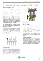
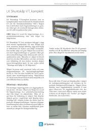
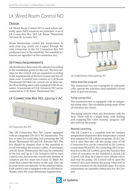
<strong>LK</strong> Connection Box <strong>NO</strong>, 230/24 V AC<br />
<strong>LK</strong> Connection Box <strong>NO</strong>.<br />
The <strong>LK</strong> Connection Box <strong>NO</strong> comes equipped<br />
with an integrated 230/24 V AC transformer. The<br />
box is used for connecting and powering the <strong>LK</strong><br />
<strong>Room</strong> Thermostat <strong>NO</strong> and <strong>LK</strong> Actuator <strong>NO</strong>. The<br />
box should be situated close to the manifold to<br />
avoid extending the actuator cables. A maximum<br />
of 8 <strong>LK</strong> <strong>Room</strong> Thermostats <strong>NO</strong> may be connected<br />
to the box and up to 5 <strong>LK</strong> Actuators <strong>NO</strong> to each<br />
control zone, however the overall total number of<br />
actuators per box must not exceed 12. Mark the<br />
zones that control the rooms on the unit. This can<br />
be done most conveniently on the attached labels.<br />
Each control zone is equipped with an LED that indicates<br />
when the room thermostat requests heat.<br />
<strong>LK</strong> Trådförbunden Rumsreglering <strong>NO</strong>.<br />
Valve exercise program<br />
The connection box has a program to automatically<br />
operate the actuators (and manifold valves)<br />
daily to prevent seizure.<br />
Pump connection<br />
The connection box is equipped with an integrated<br />
pump relay. The circulation pump stops when<br />
all actuators are closed.<br />
The pump restarts when any thermostat calls for<br />
heat. There will be a slight delay with starting<br />
and stopping.The valve exercise program will<br />
also activate the pump.<br />
Remote switching<br />
The <strong>LK</strong> <strong>Control</strong> is a complete unit for outdoor<br />
temperature dependent flow temperature control<br />
and adapted for <strong>LK</strong>’s shunt programs. If <strong>LK</strong> <strong>Control</strong><br />
is used then the volt free pump relay of <strong>LK</strong><br />
Connection box can be connected to <strong>LK</strong> <strong>Control</strong>,<br />
connections M and H1. By connecting <strong>LK</strong> Connection<br />
box to the <strong>LK</strong> <strong>Control</strong>, gives the function that<br />
when all actuators on the manifold is closed, <strong>LK</strong><br />
<strong>Control</strong> will close its <strong>Control</strong> valve (Shunt valve)<br />
and stop the pump. <strong>LK</strong> <strong>Control</strong> will re open the<br />
control valve and restarts the pump when one or<br />
several actuators on the manifold open. For more<br />
information see assembly instruction for <strong>LK</strong> <strong>Control</strong>.<br />
EN.33.C.27.0902<br />
1
Assembly instructions | <strong>LK</strong> <strong>Wired</strong> <strong>Room</strong> <strong>Control</strong> <strong>NO</strong><br />
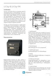
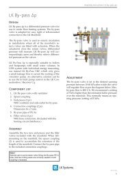
<strong>LK</strong> Actuator <strong>NO</strong>, 24 V AC<br />
<strong>LK</strong> Actuator <strong>NO</strong> opens when power is cut. A<br />
“status” indicator is located on top of the actuator.<br />
When the indicator is “up” the valve is open.<br />
The actuators are wired to “actuator terminals”<br />
of the corresponding control zone in the control<br />
box. Terminals are marked with a symbol for actuators.<br />
The <strong>LK</strong> Connection Box <strong>NO</strong> is fitted with two<br />
different sized terminals for actuators. The lower<br />
terminals are marked zone 5-8, these are intended<br />
for zones with one or two (max.) actuators. The<br />
upper terminals are marked zone 1-4 and have<br />
larger terminals to take up to four actuators per<br />
terminal. A total of five <strong>LK</strong> Actuators <strong>NO</strong> may be<br />
connected to each terminal with the aid of external<br />
connector.<br />
<strong>LK</strong> <strong>Room</strong> Thermostat <strong>NO</strong>, 24 V AC<br />
The <strong>LK</strong> <strong>Room</strong> Thermostat <strong>NO</strong> should be installed<br />
indoors 1.5 m above floor level. Avoid installation<br />
where its function might be affected (e.g.<br />
direct sunlight, vents etc.). Lit LED indicates that<br />
the room thermostat is requesting heat. Wiring<br />
between the <strong>LK</strong> <strong>Room</strong> Thermostat <strong>NO</strong> and the <strong>LK</strong><br />
Connection Box <strong>NO</strong> should be carried out using a<br />
cable such as a signal cable EKKX 4 x 0.5 mm² in<br />
which case one wire remains unused. The signal<br />
cable is connected to terminals 1, 2 and 4 on the<br />
room thermostat and to terminals 1, 2 and 4 in the<br />
connection box.<br />
English<br />
<strong>LK</strong> Actuator <strong>NO</strong>.<br />
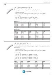
<strong>LK</strong> <strong>Room</strong> Thermostat <strong>NO</strong> white and <strong>LK</strong> <strong>Room</strong> Thermostat<br />
Dti <strong>NO</strong> silver grey.<br />
When installing in a public area, a room thermostat<br />
with a concealed temperature dial may be<br />
used namely the <strong>LK</strong> <strong>Room</strong> Thermostat Dti. The<br />
temperature dial is then placed inside the thermostat<br />
cover.<br />
Both <strong>LK</strong> <strong>Room</strong> Thermostat <strong>NO</strong> and <strong>LK</strong> <strong>Room</strong><br />
Thermostat Dti <strong>NO</strong> are available in the colours<br />
polar white and silver grey.<br />
Options<br />
An <strong>LK</strong> Remote Sensor is used when regulating<br />
the floor temperature. The sensor is placed in the<br />
floor (refer to special instructions attached to the<br />
room thermostat).<br />
An <strong>LK</strong> Protection Cover protects against external<br />
damage to the <strong>LK</strong> <strong>Room</strong> Thermostat <strong>NO</strong>. The cover<br />
is made of transparent Plexiglas.<br />
<strong>LK</strong> External Temperature Sensor<br />
<strong>LK</strong> External Sensor i intended for usage with <strong>LK</strong><br />
<strong>Room</strong> Thermostat <strong>NO</strong> or <strong>LK</strong> <strong>Room</strong> Thermostat Dti<br />
<strong>NO</strong> when the floor temperature is to be adjusted.<br />
EN.33.C.27.0902<br />
2
Assembly instructions | <strong>LK</strong> <strong>Wired</strong> <strong>Room</strong> <strong>Control</strong> <strong>NO</strong><br />
English<br />
Connect the sensor as follows:<br />
1. Remove the internal temperature sensor, as per<br />
the figure below:<br />
2. Connect an external temperature sensor to terminal<br />
11 and 12 (refer to circuit diagram).<br />
Actuator<br />
3. The supplied cable can be extended to the max.<br />
cable length of approx. 50 metres. Use at least the<br />
same cable area as the sensors when laying.<br />
4. Avoid laying parallel (on cable runs) with power<br />
wiring.<br />
The external sensor in placed as instructed below:<br />
Embedding in concrete<br />
Place the sensor in a conduit approx. 2 meters<br />
into the room before embedding in concrete. Take<br />
into consideration that the placement is at a representative<br />
point for the area that is going to be<br />
adjusted. The end of the sensor is to be placed between<br />
two floor heating pipes. Seal the end of the<br />
conduit with tape or similar to prevent concrete<br />
from getting into the conduit. Try to place the<br />
conduit as high as possible since this gives a more<br />
optimal adjustment of the floor surface temperature.<br />
The external sensor is slipped into the conduit<br />
before pouring the concrete and is connected<br />
to the room thermostat as instructed above.<br />
<strong>LK</strong> Wood 22, <strong>LK</strong> XPS or <strong>LK</strong> Silencio<br />
Mill a slot on the upper side of the board. Place a<br />
conduit in the slot, end the conduit right between<br />
two heat distribution plates. Take into consideration<br />
that the placement is at a representative<br />
point for the area that is going to be adjusted. The<br />
external sensor is slipped into the conduit before<br />
laying the floor and is connected to the room<br />
thermostat as instructed above.<br />
Floor heating in secondary spaced boarding<br />
Place a conduit right between two heat distribution<br />
plates, attach the conduit on the edge of the<br />
secondary spaced boarding using a clip for conduits.<br />
Take into consideration that the placement<br />
is at a representative point for the area that is<br />
going to be adjusted. The external sensor is slipped<br />
into the conduit before laying the floor and<br />
is connected to the room thermostat as instructed<br />
above.<br />
<strong>LK</strong> EPS 16<br />
Place a conduit along the long sides of the floor<br />
heating installation facing the nearest short end.<br />
Saw an approx. 2 meters long slot in the EPSboard<br />
and place the conduit in the slot. Take<br />
into consideration that the placement is at a representative<br />
point for the area that is going to be<br />
adjusted. The external sensor is slipped into the<br />
conduit before laying the floor and is connected<br />
to the room thermostat as instructed above.<br />
EN.33.C.27.0902<br />
3
Assembly instructions | <strong>LK</strong> <strong>Wired</strong> <strong>Room</strong> <strong>Control</strong> <strong>NO</strong><br />
<strong>LK</strong> Clip Rail 12<br />
Place a conduit along the long sides of the floor<br />
heating installation facing the nearest short end.<br />
Place the conduit at the short end between two<br />
heating pipes and end it approx. 2 meters in. Seal<br />
the end of the conduit with tape or similar to prevent<br />
concrete from getting into the conduit. The<br />
external sensor is slipped into the conduit before<br />
pouring the concrete and is connected to the room<br />
thermostat as instructed above.<br />
Function control test<br />
Once installation is complete a function control<br />
test should be carried out.<br />
1. Turn all the thermostats on fully and ensure<br />
that all LEDs are lit up on the thermostats<br />
and the box. Wait for approx 6 minutes<br />
and ensure that the status indicator for the<br />
actuators is in its highest position.<br />
2. Turn down all the thermostats to minimum,<br />
all the LEDs should be switched off and all<br />
the actuators should be closed after approx<br />
6 minutes.<br />
Troubleshooting, room control<br />
Connection box<br />
The LED should light up when the thermostat is<br />
turned on fully. If the LED does not light up ensure<br />
that there is a mains connection and that the<br />
fuse for the box is intact.<br />
<strong>Room</strong> thermostat<br />
The LED is lit up when the room thermostat is requesting<br />
heat. Ensure that all wires are properly<br />
connected. When the room thermostat is turned<br />
to min. there should be a 24 V voltage between<br />
terminal 1 and 4.<br />
Actuator<br />
The top of the actuator is equipped with a status<br />
indicator that indicates whether the actuator is<br />
open or closed. When the status indicator is at the<br />
top the actuator is open and vice versa. Actuation<br />
time approx 6 minutes.<br />
Valve<br />
When the actuator has been disconnected the<br />
valve function can be controlled by pressing the<br />
spring loaded valve spindle.<br />
Technical data<br />
<strong>LK</strong> Connection Box <strong>NO</strong><br />
Article no. 241 81 17<br />
Sizes<br />
350 x 100 x 60 mm<br />
Primary voltage<br />
230 V<br />
Secondary voltage<br />
24 V<br />
Power supply unit capacity 40 VA<br />
Cable protection class IP 20<br />
Protection class 2<br />
Primary fuse<br />
200 mAt according to IEC<br />
127-2/V<br />
Pump relay<br />
4 Amp<br />
Max number of actuators / 12<br />
connection box<br />
Max number of actuators / 5<br />
terminals<br />
Max number of thermostats / 8<br />
connection box<br />
<strong>LK</strong> Actuator <strong>NO</strong><br />
Article no. 241 75 91<br />
Sizes<br />
44 x 47 x 53 mm<br />
Voltage<br />
24 V<br />
Rated output<br />
2,0 W<br />
Cable protection class IP 54<br />
Ambient temperature 0-60 grader<br />
<strong>LK</strong> <strong>Room</strong> Thermostat <strong>NO</strong><br />
<strong>LK</strong> <strong>Room</strong> Thermostat <strong>NO</strong>, Article no 241 74 27<br />
white<br />
<strong>LK</strong> <strong>Room</strong> Thermostat <strong>NO</strong>, Article no 241 82 47<br />
silver grey<br />
<strong>LK</strong> <strong>Room</strong> Thermostat Dti <strong>NO</strong>, Article no 241 74 26<br />
white<br />
<strong>LK</strong> <strong>Room</strong> Thermostat Dti <strong>NO</strong>, Article no 241 82 49<br />
silver grey<br />
Sizes<br />
75 x 75 x 27 mm<br />
Voltage<br />
24 V<br />
Max number of actuators / 5<br />
thermostats<br />
Temperature range<br />
5-30 degrees<br />
Cable protection class IP 30<br />
English<br />
EN.33.C.27.0902<br />
4
4 A pot.-free<br />
1<br />
98927<br />
2<br />
1<br />
2<br />
Assembly instructions | <strong>LK</strong> <strong>Wired</strong> <strong>Room</strong> <strong>Control</strong> <strong>NO</strong><br />
2 3 4 7 5 6<br />
N L<br />
200 mAt<br />
98927<br />
L<br />
N<br />
1 24<br />
zone1<br />
1<br />
English<br />
4 A pot.-free<br />
N<br />
L<br />
200 mAT<br />
Transformer<br />
230 V / 24 V / 40 VA<br />
zone<br />
1<br />
1<br />
2<br />
4<br />
1<br />
zone 2<br />
2 4<br />
zone<br />
1 2<br />
3<br />
4<br />
1<br />
zone 4<br />
2<br />
4<br />
1 2 4<br />
1<br />
2 4 1 2<br />
4<br />
1<br />
2<br />
4<br />
zone 5<br />
zone<br />
6<br />
zone<br />
7<br />
zone<br />
8<br />
11<br />
10<br />
ZONE 1 ZONE 2 ZONE 1<br />
ZONE 2<br />
2<br />
1<br />
4<br />
2<br />
1<br />
4<br />
8<br />
7<br />
9<br />
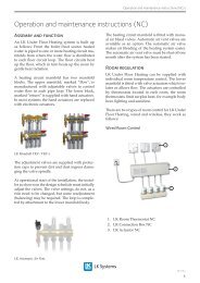
Schematic for electric connections: <strong>LK</strong> Connection Box <strong>NO</strong>.<br />
1 <strong>LK</strong> Connection Box <strong>NO</strong>.<br />
2 Pump relay, max 4 Amp.<br />
(attached pull relief)<br />
3 Connecting mains voltage, 230 V AC.<br />
4 Fuse, primary, 250 V 200 mAt.<br />
5 Connecting <strong>LK</strong> Actuator <strong>NO</strong>, 24 V AC.<br />
6 Connecting <strong>LK</strong> <strong>Room</strong> Thermostat <strong>NO</strong>, 24 AC. V<br />
7 LED.<br />
8 <strong>LK</strong> <strong>Room</strong> Thermostat <strong>NO</strong>, 24 V AC.<br />
9 Connecting to the <strong>LK</strong> Connection Box <strong>NO</strong>.<br />
10 <strong>LK</strong> Actuator <strong>NO</strong>, 24 V AC.<br />
11 Status indicator.<br />
Sample connections for a zone<br />
• Terminal 1 (9) on the room thermostat is connected to terminal 1 (6) on the connection box.<br />
• Terminal 2 (9) on the room thermostat is connected to terminal 2 (6) on the connection box.<br />
• Terminal 4 (9) on the room thermostat is connected to terminal 4 (6) on the connection box.<br />
• The actuator is connected to the terminals on the connection box marked with ”actuator symbol” (5) .<br />
EN.33.C.27.0902<br />
5