Air Top Evo 3900/5500 D (Diesel) - Techwebasto.com
Air Top Evo 3900/5500 D (Diesel) - Techwebasto.com
Air Top Evo 3900/5500 D (Diesel) - Techwebasto.com

Create successful ePaper yourself
Turn your PDF publications into a flip-book with our unique Google optimized e-Paper software.
<strong>Air</strong> Heater<br />
<strong>Air</strong> <strong>Top</strong> <strong>Evo</strong> <strong>3900</strong> / <strong>5500</strong> B (Gasoline)<br />
<strong>Air</strong> <strong>Top</strong> <strong>Evo</strong> <strong>3900</strong> / <strong>5500</strong> D (<strong>Diesel</strong>)<br />
Installation Manual<br />
WARNING!<br />
– Improper installation or repair of Webasto heating and cooling systems can cause fire<br />
or the leakage of deadly carbon monoxide leading to serious injury or death.<br />
– Installation and repair of Webasto heating and cooling systems requires special<br />
Webasto training, technical information, special tools and special equipment.<br />
– NEVER attempt to install or repair a Webasto heating or cooling system unless you<br />
have successfully <strong>com</strong>pleted the factory training course and have the technical skills,<br />
technical information, tools and equipment required to properly <strong>com</strong>plete the<br />
necessary procedures.<br />
– ALWAYS carefully follow Webasto installation and repair instructions and heed all<br />
WARNINGS.<br />
– Webasto rejects any liability for problems and damage caused by the system being<br />
installed by untrained personnel.<br />
– Improper installation or installation by untrained personnel voids all warranties on<br />
this product.
<strong>Air</strong> <strong>Top</strong> <strong>Evo</strong> <strong>3900</strong>/<strong>5500</strong><br />
Table of Contents<br />
Contents<br />
Page<br />
1. Safety and General Information 3<br />
1.1 Warning Symbols in this Installation Manual . . . . . . . . . . . . . . . . . . . . . . . . . . . . . . . . . . . . . . . . . . . . . . . . . . . . . . . . 3<br />
1.2 General Information . . . . . . . . . . . . . . . . . . . . . . . . . . . . . . . . . . . . . . . . . . . . . . . . . . . . . . . . . . . . . . . . . . . . . . . . . . 3<br />
2. Regulations for Installation in the Vehicle 4<br />
2.1 Scope . . . . . . . . . . . . . . . . . . . . . . . . . . . . . . . . . . . . . . . . . . . . . . . . . . . . . . . . . . . . . . . . . . . . . . . . . . . . . . . . . . . . . 4<br />
2.2 Position of the Heater . . . . . . . . . . . . . . . . . . . . . . . . . . . . . . . . . . . . . . . . . . . . . . . . . . . . . . . . . . . . . . . . . . . . . . . . . 4<br />
2.3 Fuel Supply . . . . . . . . . . . . . . . . . . . . . . . . . . . . . . . . . . . . . . . . . . . . . . . . . . . . . . . . . . . . . . . . . . . . . . . . . . . . . . . . . 4<br />
2.4 Exhaust System. . . . . . . . . . . . . . . . . . . . . . . . . . . . . . . . . . . . . . . . . . . . . . . . . . . . . . . . . . . . . . . . . . . . . . . . . . . . . . 4<br />
2.5 Combustion <strong>Air</strong> Inlet. . . . . . . . . . . . . . . . . . . . . . . . . . . . . . . . . . . . . . . . . . . . . . . . . . . . . . . . . . . . . . . . . . . . . . . . . . 4<br />
2.6 Hot <strong>Air</strong> Inlet . . . . . . . . . . . . . . . . . . . . . . . . . . . . . . . . . . . . . . . . . . . . . . . . . . . . . . . . . . . . . . . . . . . . . . . . . . . . . . . . 4<br />
2.7 Hot <strong>Air</strong> Outlet. . . . . . . . . . . . . . . . . . . . . . . . . . . . . . . . . . . . . . . . . . . . . . . . . . . . . . . . . . . . . . . . . . . . . . . . . . . . . . . 5<br />
2.8 Automatic Control of the Heating System. . . . . . . . . . . . . . . . . . . . . . . . . . . . . . . . . . . . . . . . . . . . . . . . . . . . . . . . . . 5<br />
3. Purpose of the Heater 6<br />
4. Installation 7<br />
4.1 Re<strong>com</strong>mended Installation Tools . . . . . . . . . . . . . . . . . . . . . . . . . . . . . . . . . . . . . . . . . . . . . . . . . . . . . . . . . . . . . . . . . 7<br />
4.2 <strong>Air</strong> <strong>Top</strong> EVO <strong>3900</strong>/<strong>5500</strong> Installation Situation . . . . . . . . . . . . . . . . . . . . . . . . . . . . . . . . . . . . . . . . . . . . . . . . . . . . . . . 7<br />
4.3 Installation Location . . . . . . . . . . . . . . . . . . . . . . . . . . . . . . . . . . . . . . . . . . . . . . . . . . . . . . . . . . . . . . . . . . . . . . . . . . 8<br />
4.4 To Install the Heater . . . . . . . . . . . . . . . . . . . . . . . . . . . . . . . . . . . . . . . . . . . . . . . . . . . . . . . . . . . . . . . . . . . . . . . . . . 8<br />
4.5 Optional Mounting Plate. . . . . . . . . . . . . . . . . . . . . . . . . . . . . . . . . . . . . . . . . . . . . . . . . . . . . . . . . . . . . . . . . . . . . . . 9<br />
4.6 Factory Plate / Label . . . . . . . . . . . . . . . . . . . . . . . . . . . . . . . . . . . . . . . . . . . . . . . . . . . . . . . . . . . . . . . . . . . . . . . . . . 9<br />
4.7 Installation Example . . . . . . . . . . . . . . . . . . . . . . . . . . . . . . . . . . . . . . . . . . . . . . . . . . . . . . . . . . . . . . . . . . . . . . . . . 10<br />
5. Hot <strong>Air</strong> System 11<br />
5.1 External Temperature Sensor. . . . . . . . . . . . . . . . . . . . . . . . . . . . . . . . . . . . . . . . . . . . . . . . . . . . . . . . . . . . . . . . . . . 12<br />
5.1.1 To Install the External Temperature Sensor . . . . . . . . . . . . . . . . . . . . . . . . . . . . . . . . . . . . . . . . . . . . . . . . . . . 12<br />
6. Fuel Supply 13<br />
6.1 Vehicles with a Carburetor Equipped Engine . . . . . . . . . . . . . . . . . . . . . . . . . . . . . . . . . . . . . . . . . . . . . . . . . . . . . . . 13<br />
6.2 Vehicles with Fuel Injection Engines . . . . . . . . . . . . . . . . . . . . . . . . . . . . . . . . . . . . . . . . . . . . . . . . . . . . . . . . . . . . . 14<br />
6.3 Vehicles with <strong>Diesel</strong> Engines . . . . . . . . . . . . . . . . . . . . . . . . . . . . . . . . . . . . . . . . . . . . . . . . . . . . . . . . . . . . . . . . . . . 14<br />
6.4 Fuel Lines . . . . . . . . . . . . . . . . . . . . . . . . . . . . . . . . . . . . . . . . . . . . . . . . . . . . . . . . . . . . . . . . . . . . . . . . . . . . . . . . . 14<br />
6.4.1 Connecting Two Fuel Lines with a Coupler Hose . . . . . . . . . . . . . . . . . . . . . . . . . . . . . . . . . . . . . . . . . . . . . . 15<br />
6.5 Fuel Metering Pump . . . . . . . . . . . . . . . . . . . . . . . . . . . . . . . . . . . . . . . . . . . . . . . . . . . . . . . . . . . . . . . . . . . . . . . . . 15<br />
6.5.1 Installation Location . . . . . . . . . . . . . . . . . . . . . . . . . . . . . . . . . . . . . . . . . . . . . . . . . . . . . . . . . . . . . . . . . . . 15<br />
6.5.2 Installation and Attachment . . . . . . . . . . . . . . . . . . . . . . . . . . . . . . . . . . . . . . . . . . . . . . . . . . . . . . . . . . . . . 16<br />
6.6 Fuel Filter . . . . . . . . . . . . . . . . . . . . . . . . . . . . . . . . . . . . . . . . . . . . . . . . . . . . . . . . . . . . . . . . . . . . . . . . . . . . . . . . . 16<br />
7. Combustion <strong>Air</strong> Supply 17<br />
8. Exhaust Pipe 18<br />
9. Combustion <strong>Air</strong> Inlet and Exhaust Lines 19<br />
10.Electrical Connections 20<br />
10.1 Heater Connection . . . . . . . . . . . . . . . . . . . . . . . . . . . . . . . . . . . . . . . . . . . . . . . . . . . . . . . . . . . . . . . . . . . . . . . . . . 20<br />
10.2 Supply Voltage Connection. . . . . . . . . . . . . . . . . . . . . . . . . . . . . . . . . . . . . . . . . . . . . . . . . . . . . . . . . . . . . . . . . . . . 20<br />
10.3 Control Element (Rheostat) Connection . . . . . . . . . . . . . . . . . . . . . . . . . . . . . . . . . . . . . . . . . . . . . . . . . . . . . . . . . . 21<br />
10.4 Installation Instructions for Control Panel MC04/05. . . . . . . . . . . . . . . . . . . . . . . . . . . . . . . . . . . . . . . . . . . . . . . . . . 22<br />
10.4.1 MC04/05 Control Panel Connections . . . . . . . . . . . . . . . . . . . . . . . . . . . . . . . . . . . . . . . . . . . . . . . . . . . . . . 23<br />
10.4.2 Combination Timer 1531 Connections . . . . . . . . . . . . . . . . . . . . . . . . . . . . . . . . . . . . . . . . . . . . . . . . . . . . . 24<br />
11.Circuit Diagrams 24<br />
11.1 Legend for Circuit Diagrams . . . . . . . . . . . . . . . . . . . . . . . . . . . . . . . . . . . . . . . . . . . . . . . . . . . . . . . . . . . . . . . . . . . 24<br />
www.webasto.us 1 Webasto Product N.A., Inc.
Table of Contents <strong>Air</strong> <strong>Top</strong> <strong>Evo</strong> <strong>3900</strong>/<strong>5500</strong><br />
12.Starting the Heater for the First Time 28<br />
12.1 Control Element Description . . . . . . . . . . . . . . . . . . . . . . . . . . . . . . . . . . . . . . . . . . . . . . . . . . . . . . . . . . . . . . . . . . .28<br />
12.2 Ventilation Mode (Optional Connection) . . . . . . . . . . . . . . . . . . . . . . . . . . . . . . . . . . . . . . . . . . . . . . . . . . . . . . . . . .28<br />
13.Fault Lock-out 29<br />
13.1 Error Code Output . . . . . . . . . . . . . . . . . . . . . . . . . . . . . . . . . . . . . . . . . . . . . . . . . . . . . . . . . . . . . . . . . . . . . . . . . .29<br />
14.Technical Data 30<br />
14.1 Electrical Components. . . . . . . . . . . . . . . . . . . . . . . . . . . . . . . . . . . . . . . . . . . . . . . . . . . . . . . . . . . . . . . . . . . . . . . .30<br />
14.2 Fuel for <strong>Air</strong> <strong>Top</strong> EVO <strong>3900</strong>/<strong>5500</strong> B (Gasoline). . . . . . . . . . . . . . . . . . . . . . . . . . . . . . . . . . . . . . . . . . . . . . . . . . . . . . .30<br />
14.3 Fuel for <strong>Air</strong> <strong>Top</strong> EVO <strong>3900</strong>/<strong>5500</strong> D (<strong>Diesel</strong>/Heating Oil) . . . . . . . . . . . . . . . . . . . . . . . . . . . . . . . . . . . . . . . . . . . . . . .30<br />
15.Version 31<br />
16.Drilling Template 32<br />
17.Notes 33<br />
www.webasto.us 2 Webasto Product N.A., Inc.
<strong>Air</strong> <strong>Top</strong> <strong>Evo</strong> <strong>3900</strong>/<strong>5500</strong><br />
Safety and General Information<br />
1. Safety and General Information<br />
1.1 Warning Symbols in this Installation Manual<br />
The purpose of safety symbols is to attract your attention to possible hazardous conditions. This manual uses a series<br />
of symbols and signal words which are intended to convey the level of importance of the safety messages. The<br />
progression of<br />
symbols is described below. Remember that safety messages by themselves do not eliminate danger and are not a<br />
substitute for proper accident prevention measures.<br />
DANGER<br />
WARNING<br />
CAUTION<br />
OR<br />
Indicates an imminently hazardous situation which, if not avoided,<br />
WILL result in death or serious injury.<br />
Indicates a potentially hazardous situation which, if not avoided,<br />
COULD result in death or serious injury.<br />
Indicates a potentially hazardous situation which, if not avoided,<br />
MAY result in minor or moderate injury or property damage.<br />
It may also be used to alert against unsafe practices.<br />
These symbols are used to alert the installer to important or useful information<br />
about proper installation of the equipment.<br />
1.2 General Information<br />
Webasto Product North America, Inc. is pleased to provide this installation manual with the AT <strong>3900</strong>/<strong>5500</strong> air heater.<br />
When installed according to the guidelines stated in this manual, you can expect your customer to enjoy many years of<br />
trouble-free heater operation.<br />
This manual represents our latest effort to produce the best technical documentation possible.<br />
In our efforts towards continuous, ongoing product improvement, we encourage our customers to write to us with<br />
their <strong>com</strong>ments or criticisms concerning this manual and the AT <strong>3900</strong>/<strong>5500</strong> air heating system.<br />
Please write to us at:<br />
Webasto Product North America, Inc.<br />
Technical Documentation Group<br />
15083 North Road<br />
Fenton, MI 48430<br />
You are also invited to fill out our online questionnaire concerning our technical documentation and web site at:<br />
www.techwebasto.<strong>com</strong><br />
If you have any immediate questions concerning this manual, the installation procedures within or the product itself,<br />
please call us at:<br />
(800) 555-4518or send a fax to:(810) 593-6001<br />
www.webasto.us 3 Webasto Product N.A., Inc.
Regulation for Installation in the Vehicle <strong>Air</strong> <strong>Top</strong> <strong>Evo</strong> <strong>3900</strong>/<strong>5500</strong><br />
2. Regulation for Installation in the Vehicle<br />
Read this installation manual in its entirety before installing this equipment.<br />
2.1 Legal Provisions<br />
2.1.1 The installation and service of Webasto heaters requires special expertise and training. Installations<br />
and servicing of Webasto products by untrained, unauthorized personnel and end-users voids all<br />
warranties and releases Webasto Product North America, Inc. and Webasto authorized distributors, dealers<br />
and their personnel from responsibility for damage to Webasto products, any resulting collateral property<br />
damage and personal injury.<br />
2.1.2 Any use, operation, installation, modification or application of the product not described in Webasto manuals,<br />
or subjecting the product to extreme or unusual conditions beyond the limits of specified performance characteristics is<br />
misuse of the product. Failure to <strong>com</strong>ply with all installation instructions is a misuse of Webasto products. The same<br />
applies for repairs without using genuine Webasto service parts. This will void the heaters “official Marks of<br />
Conformity.”<br />
IMPORTANT!<br />
All relevant state and provincial licensing regulations if any, governing the installation and use of auxiliary<br />
heating devices must be observed!<br />
2.2 Position of the Heater<br />
2.2.1 Parts of the vehicle body and other <strong>com</strong>ponents in the immediate vicinity of the heater must be protected<br />
against excessive heat and the danger of contamination by fuel or oil.<br />
2.2.2 The internal <strong>com</strong>bustion heater must not pose a fire hazard even when overheated. This requirement is<br />
deemed to have been met if care is taken during installation to ensure an adequate distance from all parts, as well as<br />
adequate ventilation and if fire-resistant materials or heat shields are used.<br />
2.2.3 The model/ Serial plate or a duplicate there of (duplicate model/ Serial plate) must be fitted in such a way that<br />
it is still clearly legible when the heater has been installed in the vehicle.<br />
2.2.4 When positioning the heater, all reasonable precautions must be taken to minimize the risk of personal injury<br />
or damage to items in the vehicle.<br />
2.2.5 A clearly visible indicator within the user's field of vision must show when the heater is switched on or off.<br />
2.3 Fuel Supply<br />
2.3.1 Fuel lines are to be installed in such a way that they remain unaffected by torsional stresses created by vehicle<br />
and engine movement.<br />
2.3.2 Fuel lines must be securely fastened to the vehicle every 12 inches (30 cm) or less along the total length from<br />
heater to fuel tank.<br />
2.3.3 Fuel-carrying <strong>com</strong>ponents must be protected against excessive heat and are to be installed so that any<br />
drippings or evaporating fuel can neither accumulate nor be ignited by hot <strong>com</strong>ponents or electrical equipment.<br />
2.3.4 In buses, fuel lines are not to be located in the passenger area or in the driver’s <strong>com</strong>partment. Fuel supply must<br />
not be by means of gravity or pressurization of the fuel tank.<br />
2.3.5 The fuel tank must be equipped with a vent cap or ventilated in another way (vent line).<br />
2.3.6 When a separate fuel supply is used the fuel filler neck must not be located in the passenger <strong>com</strong>partment and<br />
must have a tightly fitting cap to prevent any fuel leaks.<br />
Webasto Product N.A., Inc. 4 www.techwebasto.<strong>com</strong>
<strong>Air</strong> <strong>Top</strong> <strong>Evo</strong> <strong>3900</strong>/<strong>5500</strong><br />
Regulation for Installation in the Vehicle<br />
2.3.7 The type of fuel and the fuel filler neck must be clearly identified for liquid fuel heaters which have a fuel<br />
supply separate from the vehicle fuel supply.<br />
2.3.8 A label must be affixed to the fuel filler neck warning that the heater must be switched off before refuelling.<br />
An identical warning must also be included in the manufacturer's operating instructions.<br />
2.4 Exhaust System<br />
2.4.1 The exhaust outlet must be positioned in such a way that exhaust fumes cannot get into the interior of the<br />
vehicle through ventilation devices, hot-air inlets or open windows. Also note that exhaust should always point away<br />
from the direction of travel.<br />
2.4.2 Do not route exhaust <strong>com</strong>ponents within 100 mm (4 inches) of flammable materials such as fuel system<br />
<strong>com</strong>ponents, polyurethane or similar foam insulation, styene sheet installation, wood and paper products, carpet,<br />
glycol reservoirs, coolant lines, brake lines, electrical wiring, etc.<br />
2.5 Combustion <strong>Air</strong> Inlet<br />
2.5.1 The air for the <strong>com</strong>bustion chamber of the heater must not be extracted from the passenger cabin of the<br />
vehicle.<br />
2.5.2 The air inlet must be positioned in such a way that it cannot be obstructed by other objects.<br />
2.6 Hot <strong>Air</strong> Inlet<br />
2.6.1 The supply of heating air must consist of either fresh air or recirculated air and must be taken from a clean area<br />
which cannot be contaminated by exhaust fumes from the engine, the internal <strong>com</strong>bustion heater or any other source<br />
in the vehicle.<br />
2.6.2 The inlet line must be protected by a grating or other suitable means.<br />
2.7 Hot <strong>Air</strong> Outlet<br />
2.7.1 Hot air lines within the vehicle must be positioned or protected in such a way as to exclude all risk of injury or<br />
damage caused by direct contact.<br />
2.7.2 The air outlet must be positioned or protected so that it cannot be obstructed by other objects.<br />
2.8 Automatic Control of the Heating System<br />
When the engine stops, the heating system must cut out automatically and the fuel supply must be stopped within 5<br />
seconds.<br />
The heating system may remain in operation if a manual unit has already been activated.<br />
www.webasto.us 5 Webasto Product N.A., Inc.
Purpose of the <strong>Air</strong> Heater <strong>Air</strong> <strong>Top</strong> <strong>Evo</strong> <strong>3900</strong>/<strong>5500</strong><br />
3. Purpose of the <strong>Air</strong> Heater<br />
The Webasto <strong>Air</strong> <strong>Top</strong> EVO <strong>3900</strong>/<strong>5500</strong> air heaters are designed<br />
– to heat cabins, boats (<strong>Diesel</strong> Only), trucks, minibuses, vans and motor homes<br />
– to defrost vehicle windows<br />
– to heat cargo<br />
The air heaters operate independently of the engine and are connected to the fuel tank and the electrical system of the<br />
vehicle.<br />
They may be used for vehicles with either water or air-cooled engines.<br />
They are not designed for heating hazardous substances.<br />
Webasto Product N.A., Inc. 6 www.techwebasto.<strong>com</strong>
<strong>Air</strong> <strong>Top</strong> <strong>Evo</strong> <strong>3900</strong>/<strong>5500</strong><br />
Installation<br />
4. Installation<br />
IMPORTANT!<br />
The regulations governing installation on pages 4 and 5 must be adhered to.<br />
The heater must not be operated without the control unit cover (#9 below) (this will cause the heater to<br />
overheat).<br />
4.1 Re<strong>com</strong>mended Installation and Service Tools<br />
• Digital Multi-Meter - Should be a good quality VAO meter.<br />
• 1/2 Heavy-Duty, low speed drill with good quality, sharp drill bits and a selection of hole saws.<br />
• Mounting/ Drilling Templates.<br />
4.2 <strong>Air</strong> <strong>Top</strong> EVO <strong>3900</strong>/<strong>5500</strong> Installation Situation<br />
NOTE:<br />
Check the installation situation of the relevant vehicle type.<br />
4.3 Installation Location<br />
The heater may be fitted both in the interior or on the exterior of the vehicle.<br />
If it is installed on the exterior ensure that the heater is fitted in a position where it is protected from splashing water<br />
and spray.<br />
The heater must be installed in such a way that no water can ingress into it if the vehicle travels through a water hazard<br />
for which that vehicle is licensed.<br />
The openings for the <strong>com</strong>bustion air inlet port, the exhaust outlet port and the fuel line must be sealed if the heater is<br />
installed in the interior. The seal designed and supplied for this purpose must be used (see Figure 4). The same applies<br />
when using the optional mounting plate and closed cell foam gasket (see Figure 5).<br />
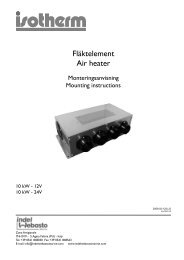
9<br />
148<br />
1<br />
2<br />
47.5<br />
162<br />
8<br />
200<br />
Ø25 Ø24<br />
6<br />
45<br />
151<br />
3<br />
5<br />
4<br />
423 80<br />
7<br />
25<br />
1. Hot air inlet<br />
2. Hot air outlet<br />
3. Combustion air inlet<br />
4. Exhaust gas outlet<br />
5. Fuel intake<br />
6. Space required for hot air inlet<br />
7. Space required for hot air outlet<br />
8. Space required for removing the heater (service)<br />
9. Cable outlet/Control unit cover (either right or<br />
left)<br />
Figure 1. Dimensions of the Heater<br />
www.webasto.us 7 Webasto Product N.A., Inc.
Installation <strong>Air</strong> <strong>Top</strong> <strong>Evo</strong> <strong>3900</strong>/<strong>5500</strong><br />
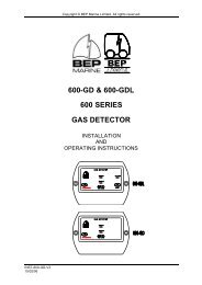
4.4 To Install the Heater<br />
The M6 nuts used to install the heater must be tightened with a torque of 6 Nm ±1 Nm (4.4 lb.-ft ± 74 lb.-ft).<br />
The installation dimensions and space requirement for service access are shown in the installation drawing (Figure 1).<br />
The specified horizontal and axial angles must not be exceeded (Figure 2).<br />
<strong>Diesel</strong> Heaters<br />
Gasoline Heaters<br />
0 - 90° 0 - 90° 0 - 90° 0 - 90° 0 - 90°<br />
0 - 30°<br />
Figure 2. Re<strong>com</strong>mended Installation Positions for AT <strong>3900</strong>/<strong>5500</strong> Heaters<br />
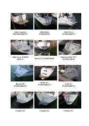
A seal (Figure 4) must be fitted between the heater and the vehicle body. This seal must be replaced each time the<br />
heater is installed. The support area for the heater foot must be flat. A special tools can be purchased from Webasto to<br />
drill the holes and, if necessary, smooth the support area. The seal can <strong>com</strong>pensate for unevenness of max. 1 mm.<br />
WARNING<br />
The seal or foam gasket or both must be replaced each time the heater is removed and reinstalled.<br />
Ø7.5<br />
Ø26<br />
Ø7.5<br />
Ø26<br />
44<br />
Ø7.5<br />
12<br />
18<br />
55<br />
Figure 3. Hole Pattern<br />
Figure 4. Seal<br />
Webasto Product N.A., Inc. 8 www.techwebasto.<strong>com</strong>
<strong>Air</strong> <strong>Top</strong> <strong>Evo</strong> <strong>3900</strong>/<strong>5500</strong><br />
Installation<br />
4.5 Optional Mounting Plate<br />
1<br />
2<br />
1. Seal - Heater to vehicle floor or optional<br />
mounting plate.<br />
2. Mounting plate - Facilitates installation on<br />
corrugated vehicle floors.<br />
3. Closed Cell Foam Gasket - Seals area<br />
between mounting plate and vehicle floor.<br />
3<br />
WARNING<br />
The seal or foam gasket or<br />
both must be replaced<br />
each time the heater is<br />
removed and re-installed.<br />
A mounting plate template is provided in the<br />
installation kit for locating the heater on the floor<br />
of the vehicle. All re<strong>com</strong>mended hole locations<br />
and sizes are included.<br />
Figure 5. Mounting with optional mounting plate<br />
CAUTION<br />
When using the optional mounting plate and closed cell foam gasket, do not over tighten<br />
the mounting bolts. Doing so will cause the mounting plate to warp and result in stress<br />
damage to the heater and fan motor.<br />
IMPORTANT!<br />
After installation, check that the heater casing is not in contact with any parts of the vehicle body.<br />
A failure to do this may result in the hot air fan binding internally (Figure 6).<br />
Ensure that all moving part can move freely<br />
Figure 6. Installation<br />
4.6 Factory Plate / Label<br />
The model/serial number plate of the heater must be positioned so that it cannot be damaged and must be clearly<br />
legible when the heater is installed (otherwise a duplicate model plate must be used).<br />
Inapplicable years must be erased from the model plate.<br />
www.webasto.us 9 Webasto Product N.A., Inc.
Installation <strong>Air</strong> <strong>Top</strong> <strong>Evo</strong> <strong>3900</strong>/<strong>5500</strong><br />
4.7 Installation Example<br />
7<br />
1<br />
6<br />
2<br />
3 4<br />
5<br />
1 Control Element (Rheostat)<br />
2 AT <strong>3900</strong>/<strong>5500</strong> EVO Heater<br />
3 Fuel Metering Pump<br />
4 Fuel Filter (Optional)<br />
5 Fuel Satndpipe<br />
6 Exhaust Muffler (Optional)<br />
7 Fuse Block<br />
Figure 7. Installation example with heater in stalled under-bunk. (Recirculation mode)<br />
Webasto Product N.A., Inc. 10 www.techwebasto.<strong>com</strong>
<strong>Air</strong> <strong>Top</strong> <strong>Evo</strong> <strong>3900</strong>/<strong>5500</strong><br />
Hot <strong>Air</strong> System<br />
5. Hot <strong>Air</strong> System<br />
NOTE:<br />
The heater must not be integrated into the vehicle’s air system.<br />
Both recirculation and fresh air modes are possible.<br />
For fresh air mode it must be ensured that the inlet (hot) air is taken from an area protected from splashing water and<br />
spray and in such a way that no water can ingress into the heater if the vehicle travels through a water hazard for<br />
which that vehicle is licensed.<br />
NOTE:<br />
For fresh air mode, an external temperature sensor must be fitted in the appropriate zone. The standard pause speed<br />
for the blower motor is 0 rpm if the external temperature sensor is used<br />
Inside the control unit there is a temperature sensor, which operates the heater in the appropriate heat output range in<br />
conjunction with the control element depending on the intake temperatures and the position of the set point<br />
generator. The heat output is controlled such that after the selected interior temperature has been reached quickly, it<br />
is then kept at this selected value.<br />
The internal diameter of the main section of the hot air line should be:<br />
90 mm (3.54 in.) minimum for the <strong>Air</strong> <strong>Top</strong> EVO <strong>5500</strong><br />
80 mm (3.14 in.) minimum for the <strong>Air</strong> <strong>Top</strong> EVO <strong>3900</strong><br />
NOTE:<br />
Only materials that can permanently withstand temperatures of at least 130°C (266°F) may be used for the hot air line.<br />
The hot air opening is to be positioned in such a way that the air is not blown on to any parts that cannot withstand<br />
the heat.<br />
IMPORTANT!<br />
In vehicles used to transport people, the air outlet opening is to be directed in such a way that it is<br />
at least 20 cm (8 in.) away from all body parts.<br />
Maximum pressure drop between the inlet and outlet side of the hot air line:<br />
<strong>Air</strong> <strong>Top</strong> EVO <strong>3900</strong> 2.0 hPa<br />
<strong>Air</strong> <strong>Top</strong> EVO <strong>5500</strong> 3.0 hPa<br />
1 hPa corresponds to 1 mbar corresponds to 10 mm Water Column (0.4 inches Water Column).<br />
The heaters check the internal temperature rise automatically each time they are switched on. If this is above the<br />
specified limits (150°C / 302°F), the start is cancelled and error messages F10 (Overheat code) is displayed. To ensure<br />
that the heater functions stably, the flow resistance of the connected hot air system must be reduced.<br />
The hot air hose must be secured at its connection points.<br />
If the heater is used in recirculation mode, for example, in the under bunk <strong>com</strong>partment of a truck’s sleeper, without a<br />
hot air directional outlet grille, do not short circuit the hot air flow.<br />
Figure 8. Hot air inlet and hot air outlet (recirculation mode)<br />
www.webasto.us 11 Webasto Product N.A., Inc.
Hot <strong>Air</strong> System <strong>Air</strong> <strong>Top</strong> <strong>Evo</strong> <strong>3900</strong>/<strong>5500</strong><br />
IMPORTANT!<br />
If you use the heater without a hot air inlet hose, the inlet grille supplied with the heater must be<br />
used at all times.<br />
NOTE:<br />
The installation must be checked for:<br />
– <strong>Air</strong> short circuit between the vehicle’s heating system and the heater air inlet.<br />
– <strong>Air</strong> short circuit between the heater’s air inlet and the heater’s air outlet (Figure 8).<br />
Figure 9. Hot air inlet with inlet grille<br />
If you use an installation box the air vent must be sealed in such a way that no hot air can get into the installation box.<br />
5.1 External Temperature Sensor<br />
The installation of an external temperature sensor is re<strong>com</strong>mended if the heater is operated in fresh air mode.<br />
5.1.1 To Install the External Temperature Sensor<br />
The external temperature sensor must be installed at medium height in the passenger cabin on vertical surfaces if<br />
possible in the area that requires heating.<br />
The temperature sensor must not<br />
– be in the direct current of hot air (from the vehicle’s own heating system or the hot air heater).<br />
– by close to heat sources (for example the vehicle’s own heating system).<br />
– be placed in direct sunlight (for example on the dashboard).<br />
– be installed behind curtains or the like.<br />
External temperature sensor<br />
Figure 10. External temperature sensor - optional<br />
Cover<br />
Webasto Product N.A., Inc. 12 www.techwebasto.<strong>com</strong>
<strong>Air</strong> <strong>Top</strong> <strong>Evo</strong> <strong>3900</strong>/<strong>5500</strong><br />
Fuel Supply<br />
6. Fuel Supply<br />
The fuel is taken from the vehicle fuel tank or from a<br />
separate fuel tank. The values for the maximum pressure at<br />
the fuel extraction point are shown in Figure 11.<br />
Permissible fuel inflow height H At max. pressure in fuel line<br />
0.00 m (0.00 in.) 0.2 bar (2.9 PSI)<br />
1.00 m (39.4 in.) 0.11 bar (1.6 PSI)<br />
I2<br />
max.3m<br />
2.00 m (78.7 in.) 0.03 bar (0.44 PSI)<br />
Maximum fuel intake height S<br />
At max. negative pressure in the<br />
fuel tank<br />
0.00 m (0.00 in.) -0.10 bar (-1.45 PSI)<br />
iØ2mm<br />
iØ2mm<br />
H<br />
0.50 m (19.7 in.) -0.06 bar (-0.87 PSI)<br />
1.00 m (39.4 in.) -0.02 bar (-0.29 PSI)<br />
iØ2mm<br />
I1<br />
A sign must be affixed to the fuel tank’s filler neck warning<br />
that the heater must be switched off before refuelling.<br />
I2<br />
I1 + I2 10 m<br />
I1 1.2 m<br />
I2 8.8 m<br />
iØ2mm<br />
I1<br />
S<br />
Figure 11. Fuel supply<br />
6.1 Vehicles with a Carburetor Equipped Engine<br />
The fuel may only be extracted using the special Webasto fuel extractor (see Figure 12) as close to the tank as possible.<br />
The connection may be made in either the supply or return line, in which case the return line must lead almost to the<br />
base of the tank (see Figure 13).<br />
The fuel extractor must be fitted in such a way that any air or gas bubbles are automatically discharged towards the<br />
tank (see Figure 12).<br />
From Tank<br />
0-60°<br />
0-60°<br />
Ø5<br />
a= 6Ø<br />
8Ø<br />
10Ø<br />
12Ø<br />
0-60° 0-60°<br />
To Engine<br />
To Fuel Metering Pump<br />
0-60° 0-60°<br />
Figure 12. Webasto fuel extractor<br />
The fuel extractor should not be located near the engine, as gas bubbles may form in the lines on account of heat<br />
radiated from the engine. This may cause problems during <strong>com</strong>bustion.<br />
www.webasto.us 13 Webasto Product N.A., Inc.
Fuel Supply <strong>Air</strong> <strong>Top</strong> <strong>Evo</strong> <strong>3900</strong>/<strong>5500</strong><br />
6.2 Vehicles with Fuel Injection Engines<br />
When installing the heater in a vehicle with fuel injection system, it is important to establish whether the fuel pump is<br />
located inside or outside the tank.<br />
If the fuel pump is located inside the tank, fuel can only be extracted from the return line using the Webasto fuel<br />
extractor (see Figure 12), in which case it must be ensured that the return line continues almost to the bottom of the<br />
tank (see Figure 13 for details of the minimum distance from the bottom of the tank). If this is not the case Webasto<br />
fuel extractors or standpipes (see Figures 13, 14 and 15) may be used.<br />
If the fuel pump is installed outside the tank, the fuel connection may also be made between the tank and the fuel<br />
pump, again using only the Webasto fuel extractor (see Figure 12).<br />
6.3 Vehicles with <strong>Diesel</strong> Engines<br />
The fuel must be taken from the vehicle fuel tank or from a separate tank (see Figs. 13, 14 and 15). This separate fuel<br />
pickup precludes any effect of pressure.<br />
Hole pattern<br />
25<br />
*<br />
Only use this Standpipe on fuel<br />
tanks constructed from metal<br />
Minimum distance 25 mm (1 in.)<br />
Figure 13. Webasto fuel standpipe<br />
NOTE:<br />
The tank fitting must be made from metal!<br />
6.4 Fuel Lines<br />
Only steel, copper and plastic lines of plasticized, light and temperature-stabilized PA 11 or PA 12 (e.g. Mecanyl RWTL)<br />
pursuant to DIN 73378 may be used for the fuel lines.<br />
Since the lines normally cannot be routed with a constant rising gradient, the internal diameter must not be allowed to<br />
exceed a certain size. <strong>Air</strong> or gas bubbles will accumulate in lines with an internal diameter of more than 2 mm and<br />
these will cause malfunctions whilst the heater is operating if the lines sag or are routed downwards. The diameters<br />
specified in Figure 11 will ensure that bubbles do not form.<br />
The lines should not be routed downwards from the metering pump to the heater.<br />
Unsupported fuel lines must be secured to prevent them from sagging. They must be installed in such a way that they<br />
cannot be damaged by flying road debris and high temperatures (exhaust line).<br />
The fuel lines must be secure at the connections using hose clamps to prevent their slipping.<br />
Webasto Product N.A., Inc. 14 www.techwebasto.<strong>com</strong>
<strong>Air</strong> <strong>Top</strong> <strong>Evo</strong> <strong>3900</strong>/<strong>5500</strong><br />
Fuel Supply<br />
Plastic tank<br />
Tank Connector<br />
Sealing ring<br />
Tank Fitting<br />
Sealing ring<br />
Figure 14. Fuel supply from plastic tank drain screw<br />
Figure 15. Fuel supply from plastic tank fitting<br />
6.4.1 Connecting Two Fuel Lines with a Coupler Hose<br />
The correct procedure for connecting fuel lines with hosing is shown in Figure 16. Ensure that there are no leaks.<br />
<strong>Air</strong> <strong>Top</strong> EVO <strong>3900</strong>/<strong>5500</strong> 12 Volt - Gasoline<br />
Correct<br />
Clamp<br />
Wrong<br />
Preferably<br />
15° - 90°<br />
Bubble<br />
Bubble<br />
Figure 16. Fuel line / coupler hose connection<br />
e 17. Fuel Metering Pump DP 2<br />
6.5 Fuel Metering Pump<br />
The fuel metering pump is a <strong>com</strong>bined delivery,<br />
metering and shut-off system and is subject to<br />
certain installation criteria (see Figures 11 and<br />
18).<br />
<strong>Air</strong> <strong>Top</strong> EVO <strong>3900</strong>/<strong>5500</strong> 12 and 24 Volt - <strong>Diesel</strong><br />
6.5.1 Installation Location<br />
It is advisable to install the metering pump in a<br />
cool place. The maximum ambient temperature<br />
must not exceed +20 °C (68 °F) for gasoline<br />
heaters at any time during operation.<br />
The metering pump and fuel lines must not be<br />
installed within range of the radiated heat from<br />
hot vehicle parts. A heat shield must be used if<br />
necessary<br />
.<br />
Figure 18. Fuel metering pump DP 30.2 / 30.3<br />
www.webasto.us 15 Webasto Product N.A., Inc.
Fuel Supply <strong>Air</strong> <strong>Top</strong> <strong>Evo</strong> <strong>3900</strong>/<strong>5500</strong><br />
6.5.2 Installation and Attachment<br />
The metering pump must be secured with a vibration-damping mounting. Its installation position is limited as shown in<br />
Figure 18 in order to ensure effective automatic bleeding.<br />
As a result of the risk of corrosion, only genuine Webasto parts may be used for the plug connections between the<br />
metering pump and the metering pump wiring harness.<br />
6.6 Fuel Filter<br />
Only a Webasto filter is allowed to be used if the fuel is expected to be contaminated. Install vertically if possible,<br />
however at least horizontally (check flow direction).<br />
IMPORTANT!<br />
Do not substitute the Webasto supplied fuel filter with a non Webasto replacement. Irregular<br />
heater operation may result.<br />
0° - 90°<br />
A<br />
Figure 19. Fuel filter<br />
Ø 5<br />
Webasto Product N.A., Inc. 16 www.techwebasto.<strong>com</strong>
<strong>Air</strong> <strong>Top</strong> <strong>Evo</strong> <strong>3900</strong>/<strong>5500</strong><br />
Combustion <strong>Air</strong> Supply<br />
7. Combustion <strong>Air</strong> Supply<br />
Under no circumstances may the <strong>com</strong>bustion air be taken from areas occupied by people. The <strong>com</strong>bustion air intake<br />
opening must not point in the direction of travel. It must be located so that it cannot be<strong>com</strong>e clogged with dirt and<br />
road debris.<br />
NOTE:<br />
An intake silencer must be fitted if the intake hose length is shorter than 0.6 m.<br />
NOTE:<br />
The <strong>com</strong>bustion air must be extracted using a <strong>com</strong>bustion air line from a position that is as cool as possible and<br />
protected from splashing water.<br />
Do not use an exhaust line as the <strong>com</strong>bustion air line since otherwise the metering pump cable from the <strong>com</strong>bustion<br />
air inlet port may be damaged.<br />
The <strong>com</strong>bustion air opening must not be under the minimum water drive-through level permitted for the vehicle.<br />
See the regulations for the installation for further regulations.<br />
www.webasto.us 17 Webasto Product N.A., Inc.
Exhaust Pipe <strong>Air</strong> <strong>Top</strong> <strong>Evo</strong> <strong>3900</strong>/<strong>5500</strong><br />
8. Exhaust Pipe<br />
Rigid pipes of unalloyed or alloyed steel with a minimum wall thickness of 1.0 mm (3/64 in.) or flexible piping of alloyed<br />
steel only must be used as exhaust line.<br />
The exhaust pipe is secured to the heater using a clamping collar, for example. See the ‘regulations for installation’ for<br />
other requirements.<br />
The exhaust muffler should ideally be installed near the heater.<br />
The heater may also be operated without a muffler.<br />
Ø 6.5<br />
0-90° 0-90°<br />
Figure 20. Exhaust muffler - exhaust flow is non-directional (arbitrary)<br />
Figure 21. Exhaust silencer for boat applications - Flow direction and installation position is non-directional (arbitrary)<br />
Webasto Product N.A., Inc. 18 www.techwebasto.<strong>com</strong>
<strong>Air</strong> <strong>Top</strong> <strong>Evo</strong> <strong>3900</strong>/<strong>5500</strong><br />
Combustion <strong>Air</strong> Inlet and Exhaust Lines<br />
9. Combustion <strong>Air</strong> Inlet and Exhaust Lines<br />
Both lines are to be installed falling away from the<br />
heater. If this is not possible, a condensate drain hole<br />
with a diameter of 4 mm (5/32 in.) must be made at its<br />
lowest point.<br />
The lines must not point to the front of the vehicle.<br />
Figure 22. Prevent the formation of condensate<br />
The lines must be located so that they cannot be<strong>com</strong>e<br />
clogged with dirt and road debris.<br />
Figure 23. Lines must not point in the direction of travel<br />
Figure 24. Avoid the lines be<strong>com</strong>ing clogged with dirt<br />
Length of the <strong>com</strong>bustion air inlet and exhaust lines in total:<br />
With muffler:<br />
max. 2.0 m<br />
Without muffler:<br />
max. 5.0 m<br />
The exhaust pipe must be securely attached no further<br />
than 150 mm (6 in.) from the end of the exhaust pipe<br />
to ensure that the angle of 90° ± 10° is maintained.<br />
NOTE:<br />
If the exhaust line is over 2 m in length the lines must be insulated<br />
(to prevent falling below the dewpoint)<br />
Internal diameter of the lines:<br />
Combustion air line:<br />
exhaust line (metal):<br />
Minimum bending radius:<br />
24 mm<br />
24 mm<br />
50 mm<br />
Installation position<br />
10°<br />
10°<br />
Total bends:<br />
Combustion air line: max. 270°<br />
Exhaust line: max. 270°.<br />
Discharge direction almost vertical 90° ± 10°<br />
Figure 25. Exhaust pipe opening<br />
IMPORTANT!<br />
If the exhaust pipe ends other than as shown in Figure 25, it will pose a fire risk.<br />
www.webasto.us 19 Webasto Product N.A., Inc.
Electrical Connections <strong>Air</strong> <strong>Top</strong> <strong>Evo</strong> <strong>3900</strong>/<strong>5500</strong><br />
10. Electrical Connections<br />
All the cables and wires that are not required must be insulated against accidental shorting or grounding.<br />
NOTE:<br />
The electrical connection is made as shown in the system circuit diagram (Figure 35).<br />
10.1 Heater Connection<br />
To connect the wiring harness, remove the control unit cover on the heater and connect the wiring harness plug to the<br />
control unit.<br />
Figure 26. To remove the control unit cover<br />
NOTE:<br />
Raise the control unit cover on both sides using a blunt blade (Figure 26 arrows).<br />
Before using the heater for the first time, fit the control unit cover in place on the heater to prevent the escape of hot<br />
air (heater overheating).<br />
The cable passage of the cover can be placed at either the left or right side.<br />
To ensure that the cable passage in the control unit cover seals perfectly, the cable grommet is to be adjusted<br />
appropriately on the wiring harness.<br />
10.2 Supply Voltage Connection<br />
Ideally from the vehicle’s central electrical system or at the batteries.<br />
A weather sealed fuse holder is to be fitted to protect the heater<br />
(supplied with the heater harness).<br />
F = 20A (12V)<br />
F = 15A (24V)<br />
Figure 27. Fuse holder - weather sealed<br />
IMPORTANT!<br />
The <strong>Air</strong> <strong>Top</strong> EVO <strong>3900</strong>/<strong>5500</strong> requires 6.25 amps @ 12 volts or 12.5 amps @ 24 volts during start-up.<br />
The main power connection has to be made at a circuit designed to sustain this load without<br />
voltage drop. Cigar lighter sockets and auxiliary power outputs for C.B. radio’s and other<br />
electronic accessories are not considered adequate power supplies for the <strong>Air</strong> <strong>Top</strong> EVO <strong>3900</strong>/<strong>5500</strong>.<br />
Webasto Product N.A., Inc. 20 www.techwebasto.<strong>com</strong>
<strong>Air</strong> <strong>Top</strong> <strong>Evo</strong> <strong>3900</strong>/<strong>5500</strong><br />
Electrical Connections<br />
10.3 Control Element (Rheostat) Connection<br />
The wiring harness is prepared for connection to the<br />
control element.<br />
Simply pull on the connector housing to unplug the<br />
connector.<br />
Shaft requires a 12 mm (15/32 in.)<br />
hole to mount.<br />
The connector housing can be locked (self-locking<br />
action) by simply pulling on the wiring harness.<br />
Locate the control element in a convenient location.<br />
The control element is not affected by temperature.<br />
Temperature is monitored inside the heater or via an<br />
optional external temperature sensor (see Figure 31).<br />
Figure 28. Control element (rheostat)<br />
NOTE:<br />
The fibre optic lens must be in contact with the rotary<br />
knob.<br />
Figure 29. Installation of the control element - correct<br />
NOTE:<br />
The rotary knob must sit flush with the bezel (Figure<br />
29) not above it as illustrated in Figure 30.<br />
Figure 30. Installation of the control element - incorrect<br />
External temperature sensor<br />
NOTE:<br />
As an option an external temperature sensor may be<br />
installed in the passenger cabin (see page12).<br />
See installation instructions included with the sensor<br />
or see the service instructions in the Workshop<br />
manual for further information.<br />
Cover<br />
Figure 31. External temperature sensor - optional<br />
www.webasto.us 21 Webasto Product N.A., Inc.
Electrical Connections <strong>Air</strong> <strong>Top</strong> <strong>Evo</strong> <strong>3900</strong>/<strong>5500</strong><br />
10.4 Installation Instructions for Control Panel MC04/05<br />
The Control Panel should be installed in a suitable location (on a flat surface if possible) in the area visible to the driver.<br />
– Use Drilling Template for Control Panel MC04/05 for cut-out and holes (see"Drilling templates")<br />
– Connect Control Panel to existing connectors on heater-unit wiring harness (see "Connection diagram/Circuit<br />
diagram")<br />
– Pre-mount control unit in cut-out<br />
– Lightly press fastening screws into holes and screw in<br />
– Carefully clip on trim frame<br />
NOTES:<br />
• Control Panel is only intended for installation in passenger <strong>com</strong>partment<br />
• Ensure good readability when selecting installation location<br />
• Observe information on adhesive labels and colored markings when connecting Control Panel to vehicle wiring<br />
harness<br />
Figure 32. Installing Control Panel MC04/05<br />
Webasto Product N.A., Inc. 22 www.techwebasto.<strong>com</strong>
<strong>Air</strong> <strong>Top</strong> <strong>Evo</strong> <strong>3900</strong>/<strong>5500</strong><br />
Electrical Connections<br />
10.4.1 MC04/05 Control Panel Connections<br />
Control Panel MC04/05<br />
Observe coloured markings<br />
Optional connection for:<br />
- Telestart/Thermo Call<br />
- Webasto Thermo Test Diagnose<br />
Heater units<br />
wiring harness<br />
Figure 33. Connection Diagram for <strong>Air</strong> <strong>Top</strong> EVO <strong>3900</strong>/<strong>5500</strong> with Control Panel MC04/05<br />
10.4.2 Combination Timer 1531 Connections<br />
12V 24V<br />
Combination Timer 1531<br />
Grey<br />
Lights (1)<br />
(optional)<br />
Black<br />
Battery Positive<br />
or Ignition Signal (10)<br />
Red<br />
Battery Positive (11)<br />
Brown<br />
Battery Negative (12, 4)<br />
3 2 1<br />
6 5 4<br />
9 8 7<br />
12 11 10<br />
Adapter Harness<br />
P/N 9008440A<br />
Figure 34. <strong>Air</strong> <strong>Top</strong> EVO <strong>3900</strong>/<strong>5500</strong> with <strong>com</strong>bination timer 1531 - connection diagram<br />
www.webasto.us 23 Webasto Product N.A., Inc.
Circuit Diagrams <strong>Air</strong> <strong>Top</strong> <strong>Evo</strong> <strong>3900</strong>/<strong>5500</strong><br />
11. Circuit Diagrams<br />
11.1 Legend for Circuit Diagrams<br />
Cable colors<br />
(where applicable)<br />
bl<br />
br<br />
ge<br />
gn<br />
gr<br />
or<br />
rt<br />
sw<br />
vi<br />
ws<br />
blue<br />
brown<br />
yellow<br />
green<br />
grey<br />
orange<br />
red<br />
black<br />
violet<br />
white<br />
Item Description Comment<br />
A1 Heater <strong>Air</strong> <strong>Top</strong> EVO <strong>3900</strong>/<strong>5500</strong><br />
A2 Control module<br />
B2 Temperature sensor Internal<br />
B3 Overheating sensor Overheating guard<br />
B4 Temperature sensor External<br />
E Ceramic glow pin<br />
F1 Fuse 24 V 15 A/12 V 20 A Flat fuse SAE J 1284<br />
F2 Fuse 20 A Flat fuse SAE J 1284<br />
F3 Fuse 15 A Flat fuse SAE J 1284<br />
H1 LED, green (in item S1) Indicator<br />
H3 LED red (in item P) Light in immediate heat button,<br />
ready indicator, Switch-on<br />
indicator<br />
H4 Heating symbol in the display Indicator<br />
(item P)<br />
H5 Light (in item P) Display and button lights<br />
H6 Light (at least 1.2 W) Switch-on indicator pumping<br />
device<br />
K Relay with free wheeling diode for vehicle fan<br />
M1 Motor Combustion and hot air fan<br />
M3 Motor Vehicle fan<br />
P Combination Timer (1531) Timer and setpoint generator<br />
R1 Resistor 620 Ohm With internal temperature sensor<br />
only<br />
S1 Control element Set point generator switch<br />
S2 1 or 2 pin disconnecting Emergency Stop switch<br />
switch<br />
S3 Switch On and for pumping device<br />
S5 Switch CO 2 setting<br />
S6 Switch Ventilation or boost<br />
S7 Momentary contact switch Immediate heat button remote<br />
control<br />
S8 Battery isolation switch<br />
V1 Diode<br />
V12 Diode<br />
X1 Plug connector, 2-pin To item A2 (B)<br />
X2 Plug connector, 2-pin To item A2 (V)<br />
X3 Plug connector, 2-pin To item A2 (U)<br />
X4 Plug connector, 2-pin To item A2 (Z)<br />
X5 Plug connector, 2-pin To item A2 (Y)<br />
X6 Plug connector, 2-pin To item A2 (X)<br />
X7 12-pin plug connection To item A2 (1)<br />
X8 Plug connector, 2-pin<br />
X9 Plug connector, 4-pin To item S1<br />
X10 Plug connector, 2-pin<br />
X11 Plug connector, 2-pin To item Y1<br />
X12 12-pin plug connection To item P<br />
Y1 Metering pump<br />
Y2 Solenoid valve for pumping device<br />
Webasto Product N.A., Inc. 24 www.techwebasto.<strong>com</strong>
<strong>Air</strong> <strong>Top</strong> <strong>Evo</strong> <strong>3900</strong>/<strong>5500</strong><br />
Circuit Diagrams<br />
Figure 35. Standard system wiring diagram for the <strong>Air</strong> <strong>Top</strong> EVO <strong>3900</strong>/<strong>5500</strong>, 12 / 24 Volt with control element.<br />
www.webasto.us 25 Webasto Product N.A., Inc.
Circuit Diagrams <strong>Air</strong> <strong>Top</strong> <strong>Evo</strong> <strong>3900</strong>/<strong>5500</strong><br />
Figure 36. Standard system wiring diagram for the <strong>Air</strong> <strong>Top</strong> EVO <strong>3900</strong>/<strong>5500</strong>, 12 / 24 Volt with <strong>com</strong>bination timer.<br />
Webasto Product N.A., Inc. 26 www.techwebasto.<strong>com</strong>
<strong>Air</strong> <strong>Top</strong> <strong>Evo</strong> <strong>3900</strong>/<strong>5500</strong><br />
Circuit Diagrams<br />
Figure 37. Standard system wiring diagram for the <strong>Air</strong> <strong>Top</strong> EVO <strong>3900</strong>/<strong>5500</strong>, 12 / 24 Volt with control panel MC04/05.<br />
www.webasto.us 27 Webasto Product N.A., Inc.
Starting the Heater for the First Time <strong>Air</strong> <strong>Top</strong> <strong>Evo</strong> <strong>3900</strong>/<strong>5500</strong><br />
12. Starting the Heater for the First Time<br />
After you have installed the heater, bleed the fuel supply system carefully.<br />
NOTE:<br />
As a result of the low fuel consumption the heater must be switched on several times to fill the fuel line and prime the<br />
system.<br />
Conduct a trial of the heater to check all the connections for leaks and to ensure that they are secure. If the heater<br />
suffers a fault during operation, the fault must be located and remedied.<br />
12.1 Control Element Description<br />
Control Element<br />
Rotary knob for:<br />
- Switching on and off<br />
- Setting the room temperature<br />
- Resetting after a fault cut-out<br />
Indicator / Error code display<br />
Changes to the settings<br />
on the control element<br />
are implemented after<br />
!a delay.<br />
Figure 38. Control element<br />
12.2 Ventilation Mode (Optional Connection)<br />
Where desired, a separate switch installed between the white/red tracer or pink wire (X7, Pin-7) and a ground point<br />
allows the user to chose between heating and ventilation mode. Refer to Figure 35, item S6 for connection detail. In<br />
ventilation mode (switch S6 ‘On’) the fan speed is regulated by the control element knob.<br />
Webasto Product N.A., Inc. 28 www.techwebasto.<strong>com</strong>
<strong>Air</strong> <strong>Top</strong> <strong>Evo</strong> <strong>3900</strong>/<strong>5500</strong><br />
Fault Lock-out<br />
13. Fault Lock-out<br />
The control unit continuously monitors the heater operation. The control unit identifies errors on individual heater<br />
<strong>com</strong>ponents and faults during operation. Should the control unit experience <strong>com</strong>ponent errors and operational faults,<br />
the heater will be shut down.<br />
The heater is shut down (fault lock-out) if:<br />
– No or incorrect start<br />
– Temperature sensor defective<br />
– Overheating sensor interrupt or short circuit<br />
– Overheating sensor installed incorrectly<br />
– Ceramic glow pin interrupt or short circuit<br />
– Fan motor overload or blocked or short circuit or interrupt<br />
– Error in the fuel metering pump or overheating guard circuit (start phase only)<br />
– Under voltage less than 10 V or over voltage greater than 15 V and for longer than 20 seconds (on 12 V heater)<br />
– Under voltage less than 20 V or over voltage greater than 32 V and for longer than 20 seconds (on 24 V heater)<br />
– Control unit defective<br />
– Overheating<br />
The fuel supply is stopped if the heater overheats.<br />
The heater continues to run in the same way as if it is switched off manually.<br />
After the heater stops the control unit will be set to fault lock-out.<br />
Overheating is indicated by the indicator flashing 10 times.<br />
Rectify the cause of the fault.<br />
To reset the fault, switch the heater on and off briefly (at least 2 seconds).<br />
If serious faults, such as overheating or no start, occur frequently, the heater will be set to fault lock-out (F 12) and can<br />
be restarted by disconnecting the supply voltage (e.g. removing the fuse).<br />
13.1 Error Code Output<br />
NOTE:<br />
An error code is generated on the control element indicator light after an error has occurred. When determining the<br />
generated code, there will be a series of 5 fast flashes after which, the error code will be generated by a sequence of<br />
long flash pulses, count only the long flash pulses to obtain the code. Error codes are shown in the table below.<br />
If the heater is fitted with a <strong>com</strong>bination timer, an error message will appear on the display of the timer after a fault<br />
occurs. If the control element is used, the error number is indicated by the indicator light flashing:<br />
F 00<br />
F 01<br />
F 02<br />
F 03<br />
F 04<br />
F 06<br />
F 07<br />
F 08<br />
F 09<br />
F 10<br />
F 11<br />
F 12<br />
F 13<br />
F 14<br />
F 15<br />
Control unit error / incorrect parameter set / warm start recognition<br />
No start (after 2 attempts to start) / no flame formation<br />
Flame failure (repeated more than 3 times)<br />
Under voltage or over voltage<br />
Premature flame recognition<br />
Temperature sensor interrupt or short circuit<br />
Metering pump interrupt or pump short circuit<br />
Fan motor interrupt or short circuit or overload or blocked<br />
Ceramic glow pin interrupt or short circuit<br />
Overheating: Resulting in permanent heater fault lock-out<br />
Overheating sensor interrupt or short circuit<br />
Heater lock-out<br />
Heater lock-out permanent<br />
Overheating sensor incorrect position<br />
Set point generator interrupt<br />
www.webasto.us 29 Webasto Product N.A., Inc.
Technical Data <strong>Air</strong> <strong>Top</strong> <strong>Evo</strong> <strong>3900</strong>/<strong>5500</strong><br />
14. Technical Data<br />
Except where limit values are specified, the technical data refer to the usual heater tolerances of ±10% at an ambient<br />
temperature of +20 °C (68 °F) and at the rated voltage and in rated conditions.<br />
14.1 Electrical Components:<br />
Control unit, motor, metering pump, lamp in the timer and ceramic glow pin / flame monitor are designed for either 12<br />
or 24 Volt.<br />
14.2 Fuel for <strong>Air</strong> <strong>Top</strong> EVO <strong>3900</strong>/<strong>5500</strong> B (Gasoline):<br />
The fuel specified by the vehicle manufacturer must be used.<br />
14.3 Fuel for <strong>Air</strong> <strong>Top</strong> EVO <strong>3900</strong>/<strong>5500</strong> D (<strong>Diesel</strong>/Heating Oil):<br />
The diesel fuel specified by the vehicle manufacturer must be used. Heating oil may also be used as long as it <strong>com</strong>plies<br />
to the normal quality available on the North American market.<br />
We know of no negative influences due to additives.<br />
If fuel is extracted from the vehicle’s tank, follow the additive instructions issued by the vehicle manufacturer.<br />
If you change to low-temperature fuel, the heater must be operated for approx. 20 minutes so that the fuel system is<br />
filled with the new fuel.<br />
The <strong>Air</strong> <strong>Top</strong> EVO <strong>3900</strong>/<strong>5500</strong> heater is also licensed for use with PME (bio-diesel), which <strong>com</strong>plies with DIN EN 14214.<br />
Heater Operation <strong>Air</strong> <strong>Top</strong> EVO <strong>3900</strong>/<strong>5500</strong> B <strong>Air</strong> <strong>Top</strong> EVO <strong>3900</strong>/<strong>5500</strong> D<br />
Type test permit<br />
EMC<br />
Heater<br />
e1*72/245*95/54*1221*00<br />
e1*2001/56*0021*00<br />
e1*2001/56*0020*00<br />
Model<br />
<strong>Air</strong> heater with evaporator burner<br />
Heat output Control range 1.7 - 3.9 (5.5) kW (5800 - 13307 Btu) 1.5 - 3.9 (5.5) kW (5118 - 13307 Btu)<br />
Fuel Gasoline <strong>Diesel</strong>/PME<br />
Fuel consumption Control range 0.17 - 0.39 (0.57) kg/h<br />
0.19 - 0.46 (0.73) I/h<br />
0.15 - 0.39 (0.55) kg/h<br />
0.18 - 0.47 (0.66) I/h<br />
Rated voltage 12 V 12 / 24 V<br />
Operating voltage range 10.5 - 16 V 10.5 - 16 /21 - 32 Volt<br />
Rated power consumption Control range 15 - 45 (116) W<br />
Max. ambient temperature:<br />
Heater:<br />
- Operation<br />
- Storage<br />
-40... +40 °C (-40... +104 °F)<br />
-40... +85 °C (-40... +185 °F)<br />
Metering pump<br />
- Operation<br />
- Storage<br />
-40... +20 °C (-40... +68 °F)<br />
-40... +85 °C (-40... +185 °F)<br />
Control element<br />
- Operation<br />
- Storage<br />
-40... +75 °C (-40... +167 °F)<br />
-40... +85 °C (-40... +1854 °F)<br />
Maximum <strong>com</strong>bustion air inlet temperature<br />
-40... +20 °C (-40... +68 °F)<br />
Adjustment range for interior temperature Control range +5... +35 °C (+41... +95 °F)<br />
Delivery rate for hot air<br />
at fan speed<br />
CO 2 in the exhaust fumes<br />
(normal function range)<br />
Heater dimensions<br />
Weight<br />
Against 0.5 mbar max. 132 (200) m 3 /h<br />
at <strong>3900</strong> (<strong>5500</strong>) rpm<br />
1 kW<br />
2 kW<br />
1.7 kW: 5.0 - 8.0%<br />
3.5/5.0 kW: 9.0 - 12.5%<br />
Length 423 ± 2 mm (16.65 ± 0.08 in.)<br />
Width 148 ± 1 mm (5.82 ± 0.04 in.)<br />
Height 162 ± 1 mm (6.37 ± 0.04 in.)<br />
5.9 kg (13 lb)<br />
1.5 kW: 5.0 - 8.0%<br />
3.5/5.0 kW: 9.0 - 12.5%<br />
Webasto Product N.A., Inc. 30 www.techwebasto.<strong>com</strong>
<strong>Air</strong> <strong>Top</strong> <strong>Evo</strong> <strong>3900</strong>/<strong>5500</strong><br />
Version<br />
15. Version<br />
<strong>Air</strong> <strong>Top</strong> EVO <strong>3900</strong>/<strong>5500</strong> B (Gasoline)<br />
<strong>Air</strong> heater for gasoline (12 V)<br />
<strong>Air</strong> <strong>Top</strong> EVO <strong>3900</strong>/<strong>5500</strong> D (<strong>Diesel</strong>)<br />
<strong>Air</strong> heater for <strong>Diesel</strong>/heating oil (12 or 24 V)<br />
www.webasto.us 31 Webasto Product N.A., Inc.
R2<br />
Drilling Template <strong>Air</strong> <strong>Top</strong> <strong>Evo</strong> <strong>3900</strong>/<strong>5500</strong><br />
16. Drilling Template<br />
Figure 39. Drilling Template for Heater Installation (Dimensions in millimeters)<br />
Ø7.5<br />
Ø7.5<br />
Ø26<br />
Ø7.5<br />
12<br />
Ø26<br />
44<br />
18<br />
55<br />
98<br />
63<br />
Figure 40. Drilling Template for MC04/05 Control Panel<br />
Webasto Product N.A., Inc. 32 www.techwebasto.<strong>com</strong>
<strong>Air</strong> <strong>Top</strong> <strong>Evo</strong> <strong>3900</strong>/<strong>5500</strong><br />
Notes:<br />
17. Notes:<br />
www.webasto.us 33 Webasto Product N.A., Inc.
Org. 05/2009 Rev. 5/2012 P/N LIT909385A<br />
Webasto Product N.A., Inc.<br />
15083 North Road<br />
Fenton, MI 48430<br />
Technical Assistance Hotline<br />
USA: (800) 555-4518<br />
Canada: (800) 667-8900<br />
www.webasto.us<br />
www.techwebasto.<strong>com</strong>