
You also want an ePaper? Increase the reach of your titles
YUMPU automatically turns print PDFs into web optimized ePapers that Google loves.
HDS-5, HDS-7,HDS-5m & HDS-7m<strong>Operation</strong> <strong>Manual</strong>
SECTION 23.0 RECREATIONAL ZONE (REC) Page 23-3TABLE 23.2: ZONE PROVISIONSZone Provision Residential Uses Non-Residential UsesParking and Accessory Buildings, Etc.In accordance with the provisions of Section 5 of thisZoning By-Law.23.2.1 SINGLE DETACHED DWELLING AND NON-RESIDENTIAL BUILDING ON THE SAME LOT:When a permitted single detached dwelling is erected, altered or used on the same lot in aREC Zone as a permitted non-residential building, a setback of 3 m (9.8 ft) is requiredbetween such buildings.23.2.2 LOCATION OF RECREATIONAL USE:Any new recreational use, except a conservation project, a wayside sand/gravel pit, or stonequarry, a public use or a flood control structure, which is located outside of a designatedsettlement, as defined in Section 2.7.2.1, shall be required to satisfy the minimum distanceseparation requirements as determined through the application of the Minimum DistanceSeparation Formula I (MDS I), in accordance with Section 2.7 of this Zoning By-Law.Any existing recreational use, except a conservation project, a wayside sand/gravel pit, orstone quarry, a public use or a flood control structure, located outside of a settlement, asdefined in Section 2.7.2.1, which is hereafter enlarged, shall be required to satisfy MDS I, inaccordance with Section 2.7 of this Zoning By-Law, or not further reduce an existinginsufficient setback relative to MDS I, whichever is the lesser.23.2.3 LOCATION OF NEW BUILDINGS OR STRUCTURES:Single detached dwellings, buildings or structures hereafter erected outside of a settlement,as defined in Section 2.7.2.1, shall be required to satisfy the minimum distance separationrequirements as determined through the application of the Minimum Distance SeparationFormula I (MDS I), in accordance with Section 2.7. of this Zoning By-Law.Existing single detached dwellings, buildings or structures located outside of a settlement, asdefined in Section 2.7.2.1, which are hereafter enlarged, shall be required to satisfy MDS I,in accordance with Section 2.7. of this Zoning By-Law, or not further reduce an existinginsufficient setback relative to MDS I, whichever is the lesser.July 7/09Township of East Zorra-Tavistock Zoning By-Law Number 2003-18
ContentsPalette....................................................................................................... 31Measure Distance..................................................................................... 33Log Sonar Data......................................................................................... 33Chart <strong>Operation</strong>............................................................................... 36Chart menu............................................................................................... 37Waypoints.................................................................................................38Routes.......................................................................................................44Trails.......................................................................................................... 48Measuring Distances on Chart page........................................................ 50Search by Coordinates............................................................................. 51Find Chart item......................................................................................... 51Map Orientation........................................................................................ 52Look Ahead............................................................................................... 52Chart categories....................................................................................... 532D and Shaded Relief ..................................................................... 53Navionics.................................................................................................. 55Radar <strong>Operation</strong> (optional)............................................................ 58Radar menu.............................................................................................. 59Adjust menu.............................................................................................. 59Guard Zones.............................................................................................64Radar Overlay........................................................................................... 65Settings Menu.................................................................................. 66Chart Settings Menu................................................................................. 75Sonar Settings (HDS-5 &7)...................................................................... 78<strong>Manual</strong> Mode............................................................................................ 79Fishing Modes ......................................................................................... 80Installation Menu....................................................................................... 81Keel Offset................................................................................................ 81Radar Settings Menu (optional)................................................................ 85Fuel........................................................................................................... 962
ContentsAlarms..................................................................................................... 100Units........................................................................................................ 101Network................................................................................................... 102Vessels (only available if connected to AIS receiver)............................. 108Simulator................................................................................................. 110Specifications: HDS-5/5m & HDS-7/7m.........................................113Unit Care..........................................................................................114Troubleshooting..............................................................................115Index................................................................................................ 1233
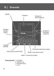
Introduction<strong>Lowrance</strong> HDS-5/7 & HDS 5m/7mZOUT: Zoom out to see more of the map with less detailZIN: Zoom in to see less of the map with more detailMOB: Pressing ZOUT and ZIN at the same time will set a man overboard waypointKEYPAD: move thecursor, scroll throughmenus, adjust features,view sonar/GPS historyEXIT: cancelsentries, closesmenus & windows;toggles betweencursor position andchart location onChart pageENTER: confirmsmenu selections;shortcut key forfunctions like savinga waypoint at cursorpositionPAGES: opens Pagesmenu; hold down thePages key to switchactive panels whenviewing combo pagesMENU: openscontext &settings menusLIGHT/POWER:controls backlightlevel & turns theunit on/offWPT/FIND: saves a waypointat current position; accessessearching toolsMMC/SD Card slot: insertMMC/SD and high-detailmapping cards here5
Getting StartedLanguageSelects language used for menus, text boxes and messages.To select a language:1. Press Menu twice.2. Select System and press ENTER3. Highlight Language and press ENTER.4. Use the keypad to select a language andpress ENTER.MenusThis unit has a Settings menu, a Pages screen and several contextmenus. The Settings menu provides access to the settings menus forthe three main operation modes: Sonar, Chart and Radar. The Settingsmenu is accessed by pressing MENU twice.The Pages screen allows you to select a page to be shown on thedisplay. Utilities are also accessed from the Pages screen. Press thePAGES key to select a page.Each page has its own context menu which allows you to accessfunctions for that page. Context menus are accessible only when itscorresponding page is displayed. The Sonar Menu, for example, willonly be available when the Sonar Page is on the display. To access acontext menu, select the desired page and press the MENU key.SettingsmenuPages screenSonar menuChart menuRadar menuClosing MenusPress the EXIT key to close a menu. Repeatedly pressing EXIT will close all menus,taking you back to the main screen.7
Getting StartedSelecting Chart DataThis unit supports <strong>Lowrance</strong> and Navionics mapdata. Chart data is selected from the Chart Settingsmenu.To select Chart data:1. Press Menu twice.2. Highlight Chart and press Enter.3. Select Chart Data and press enter.4. Select the desired map data option and press enter.Selecting a Fishing ModeFishing modes enhance the performance of your unit by providing preset packagesof sonar settings geared to specific fishing conditions.To select a fishing mode:1. Press Menu twice.2. Select Sonar and press enter.3. Highlight Fishing Mode and press enter.4. Select the desired fishing mode and pressenter.FishingModeDepth Settings PaletteGeneral Use ≤1,000 ft 50% Ping speed Bottom brown/ blue backgroundShallow Water ≤ 60 ft 75% Ping speed bottom brown/white backgroundFresh Water ≤ 400 ft 50% Ping speed bottom brown/white backgroundDeep Water ≥ 1,000 ft 50% Ping speed Deep BlueSlow Trolling ≤ 400 ft 50% Ping speed Bottom brown/white backgroundFast Trolling ≤ 400 ft Lower chart speed Bottom brown/white backgroundClear Water ≤ 400 ft 50% Ping speed Bottom brown/white backgroundIce Fishing≤ 400 ftSettings optimized to reduce interference fromother sonar units8
Getting StartedEntering Letters in Text BoxesThis unit has some features and functions that mayrequire you to enter data in a text box.To enter data in a text box:1. Highlight the text box and press ENTER.A keyboard will appear on the screen.2. Use the keypad to highlight the firstcharacter and press ENTER. Repeatthis step until all characters have beenentered.3. Highlight OK and press enter.Keypad button controlsuppercase & lowercaseKeyboard windowRestore DefaultsThe Restore Defaults command switches the unit back to the settings it had whenyou purchased it (default).To Restore Defaults:1. Press Menu twice.2. Select System and press enter.3. Highlight Restore Defaults and press Enter.4. Select each item you want to restore ordelete and press Enter.5. Select OK and press Enter.9
PagesPagesWith Chart selected, unit willdisplay a full chart screenPage iconsrotate aroundthe circularPages menuCombodisplayoptionsallows youto display asplit screenPage IconsChart icon rotated to center ofpage; has blue border indicatingit is the selected page optionPages ScreenConsists of page icons that scroll horizontally around the Pages menu. To view thepages screen, press the Pages key.Selecting PagesPressing the keypad left or right will move the page icons around the menu. Toselect a page, move the desired page icon to the center of the screen.When selected, the page name will be highlighted in blue at the top of a list ofcombo display options. Its icon, will be framed by a blue border below the list. Todisplay the page, press ENTER.NOTE: Hold down the Pages key to switch active panelswhen viewing combo pages.10
PagesData OverlayData overlay is information you can display on topof the page screen, allowing you to customize eachpage with desired data.Data Overlay menuEvery page option has its own Data Overlay menu. The menu allows you to edit,add or remove overlay data from the display. To access Data Overlay menu, selecta page option and press menu.Edit Overlay menuAccesses data overlay options for all the unit’s page screens.To access Edit Overlay menu:1. Select Edit data overlay from the Data overlaymenu and press Enter.2. Press menu. The Edit overlay menu willappear.Edit ModeWhen a gauge is added to the display it will be shown in edit mode. Analog andbar gauges are shaded in blue when they are in Edit Mode. Digital Gauges will beshown with a blue border.Analog gauge in editmodeDigital gauge in edit mode11
PagesMove or Placing a GaugeThe Move gauge command allows you to move data overlay to any position on thescreen. When you use the Place gauge command, the gauge will be locked in itscurrent position.To move/place a gauge:1. Press the Enter key when the gauge is in editmode. Four directional arrows will appear.2. Use the keypad to move the gauge into the desiredlocation.3. Press Enter to place the gauge.Select DataUsed to select data that will be shown on the data overlay display. When selectingdata you first will open a main data category and then choose data to be displayedfrom the a data subcategory.Select data menuTime subcategoryTypeSwitches data overlay display between analog, digital and bar gauge formats,provided the format is appropriate for the selected data type.To change the gauge type:1. With the gauge in edit mode, press Menu.2. Select Configure and press Enter.3. Select Type and press Enter.12
PagesTime in digital formatSizeTime in analog formatSelects the size of the data overlay display. Data overlay can be displayed in foursizes.With the gauge in edit mode (shaded in blue) press the Zoom out key to increaseoverlay size; press the Zoom in key to decrease overlay size.Small digital gaugeLarge analog gaugeLimitsControls the number scale used on data overlay gauges andselects warning thresholds.Changing the limits on an analog or bar gauge removesunnecessary numbers from the gauge, making them easierto read. Warnings help you stay within selected warningthresholds.Limits are configured by inputting analog or bar gauge limitsin the Limits text boxes — minimum and maximum. Warningsthresholds are entered in the Low and High text boxes.ConfigurationLimits menu13
PagesConfiguration menuAllows you to Add/Remove sources and adjust Bezel, Captionand Invert Text Settings. Other configuration menu options arecovered previously in the section.To access the Configuration menu, highlight Configuration onthe Edit Overlay menu and press enter.BezelCaptionInvert TextConfiguration SettingsAdds a bezel to the data overlay gauge, making it easier tosee against certain backgroundsAllows you to add/remove data label from gaugeChanges appearance of data overlay textAdd SourceDisplays the same type of data from different sources on the same analog gauge.If, for example, you have multiple engines, you could select port engine RPM as yourdata type and then display starboard engine RPM using the Add source command.Both data sources could be displayed simultaneously on an analog gauge with twoneedles; one dedicated to each source.To add a source:1. Select Add source from the Edit Overlay menuand press Enter.2. Highlight a category and press Enter. A list ofsubcategories will appear.3. Select the desired subcategory and pressEnter.Add Source menuTo remove add source data:1. Highlight Remove source on the Edit overlaymenu and press Enter.2. Select the source you want to remove and pressEnter.Showing RPM fromtwo engines.14
PagesSonar Page (Sonar units only)Displays the water column moving fromright to left on your unit’s screen. On theright side of the screen, the AmplitudeScope bar previews echoes about to appearon the display.The sonar page supports multiple splitscreenviews and 14 color palette settings. Sonardisplay options are covered in more detailin the Sonar <strong>Operation</strong> section.On the Sonar Page you can:• Move the cursor to any location on the screen to get a depth reading• Show fish echoes as fish symbols with fish depths• Adjust Range to view only desired portion of the water columnTo access the Sonar Page, use the keypad to highlight Sonar on the Pages menu andpress ENTER.Chart PageConsists of a Map that moves in real timeas you move. By default, the map is shownfrom a birds-eye view with North at the topof the screen.This page has three map orientation options(North Up, Track Up & Course Up) andtwo ways to view the map: 2D and ShadedRelief (only available on select models).The cursor is used to scroll the map, selectobjects and find the distance between objects. The Chart page is covered in moredetail in the Chart <strong>Operation</strong> section.On the Chart Page you can:• Save Waypoints• Find points of interest (POI)• Navigate routes; navigate to cursor and waypointsTo access the Chart page, use the keypad to highlight Chart on the Pages menu andpress ENTER to access the Chart Page.15
PagesRadar Page (optional)Displays the PPI (Position Plan Indicator)screen, Range Rings and the cursor.The PPI can be shifted to show more of adesired portion of the screen (Look Ahead,Center & Offset) and the color palettecan be changed to show returns in white,yellow, black or green. The radar pageis covered in more detail in the Radar<strong>Operation</strong> section.On the Radar Page you can:• Overlay compass data, range rings and EBL/VRMs on display• Choose screen orientation from Head Up, Course Up & North Up• Make radar targets more visible via Target ExpansionUse the keypad to highlight Radar on the page screen and press ENTER to accessthe Radar Page.NOTE: You will only be able to see the Radar page if your unitis connected to a radar.Info PageConsists of multiple gauges — Analog, Digitaland Bar — that can be customized to displayselected data. Customizing the info page allowsyou to monitor several types of desired data atthe same time.On the Info Page you can:• Select data to be displayed in analog gauge or digital formats• Change the page layout using one of three templates• Select the range (scale) of analog gaugesTo access the Info Page, use the keypad to select Info on the pages screen and pressenter.16
PagesInfo menuControls Info page data, page layout and data display formatselection. To access the Data menu, press Menu while on theInfo page.DashboardsLayout templates that are customized with selected data and saved for on-the-waterviewing. You can customize a different layout template for each dashboard or addcustom data to the same layout template and save it as a different dashboard eachtime.Vessel layout Navigation Layout Angler LayoutNOTE: You can toggle through the dashboard templates on thescreen by pressing the keypad left/right.EditUsed to select information displayed on the Info page. To switch the screen to EditMode, select Edit from the Info menu and press enter. The active gauge will beshaded in blue (analog) or surrounded by a blue border (digital and bar).17
PagesTo edit gauge display:1. Use the keypad to select the gauge you want toedit and press enter. The Select Info menu willappear.2. Use the keypad to select a data category and pressenter. A list of subcategories will appear.3. Select the desired subcategory and pressenter.4. Press Menu. The Edit Info menu will appear.5. Select Save and press enter.GPS categoryGround SpeedsubcategoryEditing data on an analoggaugeEditing data on a digital gaugeEdit Info menuChanges Info Page gauge data, allowing you to display desireddata on analog, digital and bar gauges. It also controls gaugelimits.To access the Edit Info menu, switch the screen to Edit modeand press menu.To select info:1. Highlight Select Info from the Edit Info menu and press enter. TheSelect Info menu will appear.2. Use the keypad to select the desired category and press enter. Alist of subcategories will appear.3. Select the desired subcategory and press enter.18
PagesTo add source:1. Select Add Source from the Edit Info menuand press enter.2. Use the keypad to select the desired categoryand press enter. A list of subcategories willappear.3. Select the desired subcategory and pressenter.To remove a source:1. Highlight Remove Source from the Edit Info menu and press enter.The Remove data-source window will appear.2. Select the source you want to remove and press enter.To Configure Limits:1. Highlight Configure Limits on the Edit Info menuand press enter. The Configure Limits menuwill appear.2. Select the desired text box and press enter.3. Use the keypad to enter the desired limit orwarning threshold.4. Select OK and press enter.NOTE: The Limits portion of the Configure Limits menu willonly be shown when configuring analog gauge limits.19
PagesChange LayoutControls the gauge layout of dashboard templates and customized dashboards. Thatallows you to select a desired gauge layout template for all dashboards.To change layout:1. Highlight the desired dashboard and pressenter.2. Select Change Layout from the Info menu andpress enter.3. Use the keypad to choose a gauge layouttemplate and press enter.Add DashboardAllows you to customize and save multiple dashboard templates. Desired data canbe added to the gauges on each dashboard, allowing you to create custom dashboardsfor a variety of fishing conditions. You can even use the same gauge layout templatefor each dashboard.When you have created all desired dashboards, press the keypad left/right to togglethrough your dashboards.To add a dashboard:1. Select Add Dashboard from the Info menu and press enter. TheChange Layout menu will appear.2. Select the desired gauge layout and press enter. Refer to theprevious Edit segment to customize the dashboard.20
PagesCopying a screenshotCopy File screenData files/Sonar logsTo copy data files/sonar logs:1. Highlight Files from the Utilities menu and press enter.2. Select the desired File category and press the keypad to the right. Alist of subcategories will appear.3. Select a subcategory and press the keypad to the right. Highlightthe desired data file/sonar log.4. Press Menu. Highlight Copy and press enter. The Copy Filescreen will appear.5. Select a place to copy the file, like an MMC card. Press enter.To delete data files/sonar logs:1. Highlight Files from the Utilities menu and press enter.2. Select the desired File category and press enter. A list ofsubcategories will appear.3. Select a subcategory and press enter.Highlight the desired data file/sonar log.4. Press Menu, select Delete and press enter.A confirmation message will appear.5. Select Yes and press enter.22
PagesInfo selected as combodisplay optionGPS/Info combo pageDisplaying Combo PagesYou can display multiple pages at the same time by scrolling the desired page’sicon to the center of the screen and then choosing a secondary page from the list ofcombo page display options.To display a combo page:1. Use the keypad to select the first page for the combodisplay. This is the primary page, which will bedisplayed in the left panel.2. Select another page from the primary page’s combodisplay list. This is the secondary page. It will bedisplayed in the right panel.3. Press Enter. The selected combo page will bedisplayed.Primary pageSelecting an Active PanelWhen combo pages are displayed only one panelcan be active at a time. The panel outlined with anorange border is the active panel. You will onlybe able to access the context menu of the activepanel. Pressing the Menu key will open the activepanel’s context menu.To switch the active setting to the other panel, holddown the Pages key for 1 second.SecondarypageChart panel is active asshown by the orange border23
PagesDisplaying Multiple Panels (Sonar units only)Multiple panels can be displayed by setting up a combo display using a page thatsupports the Split feature. By displaying multiple panels, you can view moreinformation on the screen at one time.Step 1: Select sonar split screenStep 2: Choose page fromcombo display options listTo display multiple panels:1. Select a Split view for the sonar page. (Accessing the Split featureis covered in detail in the Sonarsection.)2. Press the Pages key and usethe keypad to center the Sonaricon on the screen.3. Use the keypad to select InfoPage from the combo pagedisplay list. Press Enter. Thecombo page will be displayedwith the Sonar split view on theleft; the Info page on the right.Flasher, normal sonar and theinfo page shown on a multi-paneldisplay.Adjust Panel SizesControls the size of panels when combo pages ormulti-panels displays are in use. Adjusting the sizeof the panels, allows you to emphasize the panelyou want to see more clearly.Panels can only be adjusted left/right, sothe panels on the side with the split viewcan not be adjusted vertically.Adjust panel sizes selectedon the Data Overlay menu24
PagesMoving panel cursor left/right will change the sizeof each panelAdjusting panels on combo page(Sonar/Info combo shown)Adjusting panels on multi-panel display(Sonar/Info combo shown)To adjust panel sizes:1. With the combo page or multi-panel display on the screen, pressthe Pages key.2. Press menu. Highlight Adjust Panel Sizes from the Data Overlaymenu and press enter.3. Press the keypad left/right to adjust the panels to a desired size andpress enter.25
SonarSonar <strong>Operation</strong> (HDS-5 & 7 only)Water columnSurface clutterTemperature GraphFish ArchesRangescaleCursor depthDepthLineBrushWater depth, watertemp and cursorcoordinatesColorlineTo access the Sonar Page:1. Press the Pages key.Blue sonar history bar; reviewsrecent sonar history2. Use the keypad to select Sonar and press ENTER.CursorCursorAmplitude Scope— shows amplitudeof real-time sonarechoesBlue sonar history barViewing Sonar HistoryYou can review your recent sonar historyby moving the cursor to the left until thescreen starts to move in reverse.To resume normal operation, move thecursor all the way to the right of thescreen or press Exit.26
SonarColorlineDistinguishes strong sonar echoes fromweak sonar echoes. That makes it easier foryou to distinguish fish or structure from thebottom.Wide yellow hardsonar returnReddish-blue softsonar returnsA hard return will be shown as a wide, brightyellow line, whereas a soft return will be anarrow reddish-blue line.RangeRange set to 60 feetUsed to select the section of the water column —from surface to bottom — shown on the display.When there is a portion of the water column youwant to focus on, select a range from the DepthRange menu that includes the desired area.The values on the Range menu determine the depthshown on the display. If you selected 20m from therange menu the unit will display 0-20m of the watercolumn, regardless of the water depth. There are21 depth ranges, including automatic and customsettings. The automatic setting will set the range from the water surface to waterdepth.FrequencyThis unit supports three transducer frequencies; two of which are supported by yourtransducer. 200 kHz has the highest sensitivity and best target discrimination inshallower water; 83 kHz offers a wider cone angle for greater water coverage and50 kHz provides the best depth penetration. You can view both available frequenciesat the same time by setting up a sonar split screen.SplitAdjusts the configuration of sonar page display using one of four options: No Split,Zoom, Bottom Lock and Flasher. 28
SonarZoom display Bottom Lock Flasher Display• No Split — displays full sonar screen• Zoom — splits display with a zoomed-in panel on the left (pressZoom key to increase zoom) and a normal sonar view on the right• Bottom Lock — splits the display with a 2X zoom on the left; a normalsonar view on the right. Keeps the bottom on the screen at all times.• Flasher — splits the display with a flasher-style sonar on the left; anormal sonar view on the rightStop SonarPauses the sonar chart, allowing you to get a closer look at sonar echoes.AdjustSensitivity and Colorline can also be adjusted from the Sonar menu by using theAdjust command.To Adjust Sensitivity and Colorline:1. Highlight Adjust on the Sonar menu and press ENTER. Press thekeypad up/down to select the Sensitivity or Colorline scrollbar.2. Press the keypad left/right to make adjustments.3. Press Exit.29
SonarCustom — Upper and Lower LimitsControls not only the depth range (lower limit), butalso lets you choose the upper limit. So, instead ofa selecting a range that includes the water surface,you can choose upper and lower limits anywherealong the water column.To set Upper and Lower Limits:1. Select Range and press ENTER.2. Highlight Custom and press ENTER.The Upper and Lower Limit windowwill appear.Upper limit is 15’ (4.5m); lowerlimit is 65’ (19m).3. Select the Upper or Lower Limit dialog box. Press ENTER. Thenumerical keypad will appear.4. Use the keypad to enter the desired value in the correspondingupper or lower limit dialog box. Press ENTER.5. Repeat Steps 3 and 4 to input the desired limit in the other dialogbox.Ping SpeedPing Speed controls the rate the transducer uses tosend sonar waves into the water. A higher ping speedwill yield the best results when you are moving acrossthe water at a high rate of speed or fishing from a dock. The reverberation of toomuch ping speed can cause interference on the screen.When using two units on your boat, lowering the ping speed of one of the units willprevent interference (cross-talk) caused by one transducer detecting pings from theother transducer. The default setting is suitable for most conditions. Highlight PingSpeed on the Sonar menu and press the keypad left/right to make adjustments.Sonar OptionsAdjusts display settings and the configuration of the display.The Sonar Options menu allows you to split the screenbetween two sonar views, change the color of the display,use Fish ID and add graphical elements to screen that willenhance your sonar experience.To access the Sonar Options menu, select Sonar Optionsfrom the sonar menu and press ENTER.30
SonarTo select a Split option:1. From the Sonar Options menu,highlight Split and press ENTER.The Split menu will appear.2. Use the keypad to select the desiredoption and press ENTER.PaletteSonar display color templates with varying degrees of colorand brightness. On the Palette menu, you can select a sonardisplay template suited for your fishing conditions from 14palette options.A bottom brownpalette clearlyseparates fishand structure fromthe bottomPalette menuTo select a Palette:1. From the Sonar Options menu, highlight Palette and press ENTER.2. Use the keypad to select the desired palette and press ENTER.31
SonarTemperature GraphUses a red line graph with digital display atthe top of the screen to illustrate changes inTemperature. The Temperature graph makes iteasier to recognize temperature trends.To turn the Temperature Graph on/off, highlightTemperature Graph on the Sonar Options menuand press ENTER.Depth LineDisplays a dark line over the bottom surface,making it easier to distinguish the bottom fromfish, trees and other objects.To turn on/off the Depth Line, select Depth Lineand press ENTER.Temperature graphDepth LineAmplitude ScopeAllows you to see the amplitude of real-time echoes as they appearon the display. The Amplitude Scope displays live returns even whenyou are viewing your sonar history. To turn off the Scope, highlightAmplitude scope on the Sonar Options menu and press ENTER.Amplitude ScopeZoom BarsWhen your unit is in Split Zoom mode, zoom bars show which echoes will bedisplayed on the screen when the display is zoomed in to a particular zoom range.Only echoes shown between the top and bottom of a zoom bar will be displayed atthat selected zoom range.To turn on/off Zoom Bars, highlight Zoom Bars on the Sonar Options menu andpress ENTER.NOTE: When the screen is zoomed, you can use the ZoomPan feature to scroll up and down the water column. Thatallows you to see portions of the water column not visible atthe selected zoom range. When turned on, Zoom Bars willappear when the Zoom in key is pressed.32
SonarFish IDDisplays fish echoes as fish symbols instead offish arches with or without depth. This makesit easier to recognize fish on the sonar display.Symbols — places a fish symbol where afish is detected.Depths — places depths above each fishdetected; helps gauge the distance from eachfish symbol to the boat.Both — turns on both Symbols and Depths.Fish Symbols and DepthsTo select a Fish ID option:1. Highlight Fish ID and press Enter.2. Select Symbols, Depths or Both and press ENTER.Fish ID Beeps — sounds a tone when the system detects a fish.Measure DistanceUsed to measure the distance from one location to another on the sonar display.To Measure distance:1. Move the cursor to the starting location.2. Select Measure distance on the Sonar menu and press Enter.3. Move the cursor to the second location. The Measure distance linewill appear with the distance between the two locations shown in thecursor dialog box.4. To measure another position, press Enter and move the cursor tothe desired location.Log Sonar DataUsed to save sonar chart data to your unit’s internalmemory or to an MMC/SD card.To access the Sounder Logging menu, selectLog Sonar Data from the Sonar menu and pressENTER.33
SonarFilenameSave toBytesLog All ChannelsTime RemainingLog Sonar MenuInput the desired name for the sonar log fileSelects location where sonar log will be saved/storedControls number of bytes per sounding. More bytes yieldsbetter resolution/shorter logging time; conversely, fewerbytes produces longer sonar logs/lower resolutionSaves returns from all active sonar frequencies and fromboth StructureScan modes – Downscan & Sidescan – in asingle sonar log (StructureScan sold separately)Recording time left until memory storage runs outTo input filename:1. Highlight the Filename text box andpress enter. A keyboard will appearon the screen.2. Use the keypad to input the desiredfilename.3. Select OK and press enter.Filename keyboardInternal selected on device menuBytes per soundingmenuTo select Save to or Bytes per Sounding:1. Highlight Save to or Bytes per Sounding from the Sounder Loggingmenu and press enter.2. Use the keypad to select the desired option and press enter.34
SonarStart LoggingA sonar log is a recording of sonar activity displayed onthe sonar page.To record a sonar log, highlight the Start Logging buttonand press enter.When a sonar log is being recorded, a blinking red circlewill be displayed in the upper left-hand corner of thescreen and a logging message will appear periodicallyat the bottom of the screen.To stop logging:1. Select Stop from the Sounder Loggingmenu and press enter. The StopLogging menu will appear.2. Highlight the Stop Logging buttonand press Enter.Indicator blinks whensonar is being recordedStop Logging menuSourceAllows you to select the sonar source for your unit. You can select your unit as thesource, or choose another unit on your ethernet network, allowing you to share sonarreturns from one unit with other units on the network.To share/receive sonar data:1. Press Menu twice, select Sonar and press Enter. Make sure theunits sharing sonar have network sonar turned on.2. Press Exit twice.3. Access the Sonar page, on the unit that will be sharing its sonar(master).4. Press Menu, select Source and press Enter.5. Select This unit and press Enter.6. Press Exit.NOTE: To stop receiving shared sonar, turn off network sonaron the desired units.35
ChartChart <strong>Operation</strong>Point of Interest (POI)WaypointChart orientation indicatorCursor coordinatesCurrent position icon CursorChart page in 2D Chart modeMap scaleTo access the Chart page:1. Press the Pages key.2. Use the keypad to select the Chart icon and press Enter.The previous image shows items you will see on the chart page:• Point of Interest (POI): A position represented by a symbol orcharacter.• Cursor: Used to view specific areas on the Chart page, select POIs,create waypoints and measure distances. When the cursor is onscreen,pressing the Exit key will toggle between the cursor's locationon the Chart page and your actual position.• Chart orientation indicator: Indicates the current direction the Chartpage is facing.• Cursor coordinates: Displays the coordinates of the cursor.• Waypoint: An electronic address based on the latitude and longitudeof a selected location.• Map Scale: Represents the relationship between the distance onthe Chart page and the real distance on the earth's surface.• Current position icon: Represents your current position.36
ChartFind Current PositionPower on the unit and display the Chart page. The current position icon representsyour current position on screen. The icon always points to your heading.If the current position icon displays a question mark then the unit has notachieved a satellite lock and is not tracking your current position. Whensufficient satellites are received to determine a position, the icon's movement willcorrespond with your movement.Chart menuUse the Chart menu to adjust settings and enter commands.From this menu you have access to routes, waypoints, info,chart options and screen settings.To open the Chart menu, go to the Chart page and press theMENU key. The following features are listed in the order theyappear on the Chart menu, top to bottom:• New Waypoint: Creates a new waypoint.• New Route: Creates a new route.• Go to Cursor: Navigates to the cursor position on the Chart page.• Find: Opens the Find menu. From the Find menu you can search foritems by select categories.• Info: Shows a list of items close to the cursor.Chart menu• Measure: Used to measure the distance between current positionand another point on the Chart page or between two different points.• Overlay: Toggles weather and radar overlay on or off (Radar andWeather module sold separately)• Chart options: Opens the Chart options submenu which containsthe Map Orientation, Look Ahead, Chart categories and Imagery features.Chart Options menuControls chart features and options including MapOrientation, Chart Detail, Look Ahead, Chartcategories and Imagery.37
ChartOrientationChart detailLook aheadCategoriesImageryChart OptionsControls the way the Chart page moves in relation to yourmovement. (North Up, Heading Up and Course Up)Controls level of map detail (Full, Medium, Low)Shows more of the map area in front of youOpens chart categories display settings listToggles 2D and Shaded Relief map display settings (onlyavailable on select US models)Go To CursorThe Go To Cursor command is a quick and easy way to navigate to anything yousee on the Chart page.To go to cursor:1. Move the cursor over the desired location.2. Press Menu, select Goto and press Enter.Selecting POIs on Chart page with CursorTo select a Chart page POI:1. From the Chart page use theArrow keypad to center thecursor over a POI. A pop-upbox will appear describing thePOI. The POI's coordinates aredisplayed in the lower left handcorner of the Chart page.WaypointsA waypoint is the latitude and longitude of a specific position on the earth's surface.You can quickly create a waypoint at your current position or you can create a waypointat the cursor's position on the Chart page. You also can create a waypoint atany location by manually entering the position's latitude and longitude.38
ChartWaypoints are important because they can be saved in the unit and later used to findyour way back to a specific location, such as a favorite fishing spot or an importantgeographical feature. To quickly save a waypoint at the vessel's current positionpress the WPT/Find key.Create Waypoint from Chart pageTo create a Waypoint at the cursor's position:1. Place the cursor on the Chartpage where you want to set thewaypoint and press Entertwice. The New Waypoint menuwill appear.2. Select Save from the NewWaypoint menu.New Waypoint at Cursor menuTo create a Waypoint at the Vessel's position:1. Press the MENU key. From the Chart menu select New Waypoint.2. When the New Waypoint at Vessel menu appears, select Save.NOTE: You can also create a waypoint at the vessel's positonby pressing the WPT key.To Navigate to a Waypoint from the Waypoints screen:1. From the Pages screen select Waypoints, routes, trails, press ENTER.When the Waypoints screen appears select the waypoint you want tonavigate to from the waypoints list and press MENU. The Waypointsscreen menu will appear. From the Waypoints screen menu selectGo to.39
ChartWaypoint nameWaypoint iconDistance andBearingWaypoint latitudeand longitudeTime and date thewaypoint wascreatedWaypoints screenTo view stored waypoints go to the Waypoints screen in the Utilities page. From theWaypoints screen you can view and edit stored waypoints.Waypoints screen menuTo open the Waypoints screen menu, press theMENU key from the Waypoints screen.EditNewShowGo toDeleteSortDelete AllFindWaypoints Screen menuOpens the Edit Waypoint menuOpens the New Waypoint menuShows selected waypoint on the chartNavigates to selected waypointDeletes the selected waypointControls how waypoints are sorted on the waypoints screenDeletes all waypointsUse to search for waypoints from the waypoints screen40
ChartWaypoints screen, Search for Waypoint by nameIf the waypoint list contains too many waypoints to search through manually, youcan search for a specific waypoint by name.To Search for Waypoint by Name:1. From the Waypoints screen press theMENU key. The Waypoints screenmenu will appear.2. From the Waypoints screen menuselect Find. A keypad will appear.Use the keypad to enter the name ofthe waypoint you are searching forand press OK.Waypoints screen, Sort WaypointsYou can choose how waypoints are sorted inthe Waypoints list by selecting Sort from theWaypoints screen list menu.Waypoints can be sorted by Name, Nearest orIcon. By default the unit stores waypoints byname.Waypoint Information screenWhen a waypoint is saved to the Chart page, youcan view detailed information about that savedwaypoint.To view waypoint information:1. Place the cursor over the waypointand press the MENU key.2. Select Info and press enter.41
ChartEditing a Waypoint on the Chart pageTo Edit a Waypoint from the Chart page:1. Place the cursor over the waypoint and press the ENTER key. TheEdit Waypoint menu will appear.Edit Waypoint menuThe Edit Waypoint menu is used to edit waypoint settings and coordinates. Use thismenu to change the name, icon, color and description of a waypoint.Select More from the Edit Waypoint menu and the following edit options willappear:NamePositionIconColorDescriptionDisplayDepthAlarm RadiusDeleteSaveCancelEdit waypoint — More optionsEdit the name of a waypointEnter a latitude or longitude for a waypointSelect a different waypoint iconChange waypoint icon colorInput additional waypoint informationControls how a waypoint will be shown on the chartSelect waypoint depthDistance from a waypoint where arrival alarm will soundThis will delete a waypointSaves your waypoint changesCancels any waypoint changes42
ChartEdit Waypoint name, description, position or depthTo Edit Waypoint name or description:1. From the Edit Waypoint menu, select the Name or Description textbox and press ENTER. The Waypoint keypad will appear.2. Use the keypad to enter the desired waypoint name and select OK.To Edit Waypoint position:1. From the Edit Waypoint menu select thelatitude/longitude and press enter.2. Use the Arrow keypad to input the desiredlatitude or longitude and select OK.To Edit Waypoint depth or alarm radius:1. From the Edit Waypoint (More) menu select the Depth or Alarmradius text box and press enter. A numerical keypad will appear.2. Input the desired depth or alarm radius and press ENTER.Edit Waypoint icon and colorYou can change the default waypoint icon and color from the Edit Waypoint menu.Edit Icon menuUse the Edit Icon menu and EditIcon Color menu to change theappearance of icons on the Chartpage.Icon color palette43
ChartRoutesRoutes make it easier to plan trips to desired destinations and backtrack to a previouslocation. A route is a series of waypoints linked together to mark a course of travel. Aroute must have at least two waypoints. The route segment between two waypointsis called a leg. A route gives you the ability to navigate to several waypoints inan ordered sequence without having to manually select the next waypoint in theseries.Create Route from Chart pageTo create a new route open the Chart menu and select New Route. You can use thecursor on the Chart page to create a route.To Create a New Route from the Chart page:1. Press the Menu key and select New Route from the Chart menu,press enter.2. Move the cursor to the start of the route and press ENTER to setthe first waypoint. Move the cursor to the next location and pressENTER to set a second waypoint.3. Repeat Step 2 until you have set all the desired waypoints alongthe route.4. Press the MENU key to open the Edit route menu. Select Save andpress ENTER. The route will be saved to the Routes screen.44
Chart5. From the Routes screen highlight the route and select Start. TheStart Route message box will appear, select Forward.Routes screenTo view stored routes go to the Routes screen in the Utilities page. From the Routesscreen you can view and edit stored routes.Route nameStart of routeEnd of routeNumber of legsin routeRoutedistance45
ChartRoutes screen menuFrom the Routes screen menu you can create a newroute, edit a route or start a route.To open the Routes screen menu, from the Routesscreen, press the MENU key.EditNewShowStartDeleteDelete AllFindRoutes Screen menuOpens the Edit Route screenOpens the New Route screenShows the Route on the Chart pageSelect to start navigating a routeDeletes a selected routeDeletes all routesUse to search for routes in the Routes screenTo Edit Route:1. From the Routes screen selectthe route to be edited and pressENTER. The Edit Route screenwill appear.2. From the Edit Route screen youcan edit the route name, displayand waypoints in the route.3. Use the Arrow keypad to selectwhich route feature you want toedit and press ENTER.Edit Route screenTo Display / Hide Route:1. From the Routes screen select the route from the routes list, pressENTER. The Edit Route screen will appear.2. Highlight the Display check box and press ENTER to either Displayor hide the route from the Chart page.46
ChartTo Insert, Edit or Remove Waypoints from a Route:1. From the Routes screen select a route from the route list, pressENTER.2. The Edit Route screen will appear.Select a waypoint from the Waypointlist, press MENU. A small submenuwill appear with the options: Insert,Edit and Remove.3. Select Insert and press ENTER toinsert a waypoint into the route. Toremove a waypoint select Remove.Selecting Edit will bring up the EditWaypoint dialog.To Navigate Route from Routes screen:1. Select the route you want to navigate and press MENU. The Routesscreen menu will appear.2. Select Start from the Routes screen menu The Start Route dialogwill appear. Select Forward to navigate the route forward or Reverseto navigate the route in reverse.To Search for Route by Name:1. From the Routes screen press MENU. The Routes screen menuwill appear.2. From the Routes screen menu select Find. A keypad will appear.Use the keypad to enter the name of the route you are searching forand press OK.47
ChartTrailsA trail is a record of the path you have traveled. Trails not only show you where youhave been, they can be used to retrace your path back to your starting point. On theChart page a trail is presented by a solid line extending from the back of the currentposition icon.From the factory, the unit is automatically set to create and record a trail when theunit is turned on and you are navigating. The unit will continue to record a trail untilthe trail length reaches the maximum trail point setting.When the unit reaches the maximum trail point number it will automatically beginrecording the trail over itself. By default, the unit places a dot (trail point) on theChart page every time you change course.Shows if trail isbeing recordedIndicates if Trail isdisplayed on ChartTrail nameTrail colorNumber ofTrail pointsTrails screenTo view stored trails go to the Trails screen in the Utilities page. From the Trailsscreen you can view and edit stored trails.Trails screen menuFrom the Trails screen menu you can createa new trail, edit a trail or delete a trail.To open the Trails screen menu, press theMENU key from the Trails screen.48
ChartEditNewShowDisplayRecordDeleteDelete AllFindTrails screen menuOpens the Edit Trail menuOpens the New Trail menuDisplays the trail on the chartTurns on/off trail display on ChartSelect or deselect to actively record a trailDeletes a selected trailSelect to delete all trailsUse to search for trails in the Trails screenNew Trail menuYou can edit a trail from the New Trail menu or from the Edit Trail menu once atrail is created.To Create a New Trail:1. From the Pages screen, select Utilities and press ENTER. TheWaypoints and Routes screen will appear.2. From the Waypoints and Routesscreen select Trails. The Trails screenwill appear.3. Press MENU. The Trails screen menuwill appear.4. Select New, press MENU. The NewTrail menu will appear, select Save.Edit Trail menuThe Edit Trail menu is used to edit trail settings and coordinates. Use this menu tochange the trail name, trail color and description of a trail.To edit a Trail name:1. From the Trails screen select thedesired trail and press ENTER. TheEdit Trail menu will appear.2. Select the trail name box and pressENTER.3. Enter the trail name and select OK.49
ChartTrail line Color optionsYou can change the default trail line color from the Edit Trail More menu by selectingthe Trail line color palette option.Trail line colorpalette menuNOTE: If you record several overlapping trails, changingthe color of the different trail lines is a good way to keep themseparate when viewing them on the Chart page.Measuring Distances on Chart pageUse the Measure feature to measure distances between your location and anotherposition on the Chart page, or between two different positions.To select/deselect Measure feature:1. Move the cursor to the starting location.2. Select Measure on the Chart menu and press Enter.3. Move the cursor to thesecond location. TheMeasure Distance line willappear with the distancebetween the two locationsshown in the cursor dialogbox.4. To measure the distanceto another position, pressEnter and move the cursor to the desired location. Press Exit toreturn to normal operation.50
ChartSearch by CoordinatesTo search for Chart page POI using coordinates:1. From the Chart page press the MENUkey. The Chart menu will appear, selectFind. The Find menu will appear.2. From the Find menu select Coordinate.The Find Coordinate keypad will appear.Use the keypad to enter the desiredcoordinates and select OK.Find Chart itemTo search for specific Chart page item:1. From the Chart page press the MENU key. The Chart menu willappear, select Find. The Find menu will appear.2. From the Find menu select Chart Items. The Find - Chart Itemsscreen will appear. Select Name, a keypad will appear. Use thekeypad to enter the name of the chart item and select OK.To view a list of specific Chart POI search options select Category from theFind - Chart Items screen. A drop down list will appear. Select the specificcategory from the drop down list.51
ChartMap OrientationTo change Chart page orientation:1. From the Chart page press theMENU key. The Chart menuwill appear, select Chart options.The Chart options submenu willappear.2. From the Chart options submenuselect Map Orientation. The threeMap Orientation options are: NorthUp, Heads Up and Course Up.North UpHeading UpCourse UpMap OrientationDisplays the Chart page with North always at the topof the screenDisplays the Chart page in the direction the boat isfacingDisplays the Chart page at the same orientation asyour initial bearing to a destinationLook AheadKeeps your current position at the bottom of the Chart page to display more maparea in front of you.To select / deselect the Look Ahead feature:1. From the Chart page press the MENU key. The Chart menu willappear, select Chart options. The Chart options submenu willappear.2. From the Chart options submenu select or deselect Look Ahead toturn this feature on or off.52
ChartChart categoriesUse the Chart Categories screen to control what you want to see on the Chart page.To select / deselect Chart Categories:1. From the Chart page press MENU.The Chart menu will appear; selectChart options. The Chart optionssubmenu will appear.2. From the Chart options submenuselect Chart categories. The ChartCategories screen will appear.Select or deselect the chart optionsyou want to display on screen.2D and Shaded Relief(Shaded Relief only available on U.S. Insight models)To select between 2D and Shaded Relief:1. From the Chart page press the MENU key. The Chart menu willappear. From the Chart menu select Chart options. The Chart optionssubmenu will appear.2. From the Chart options submenu select Imagery. The Imagery dropdown menu will appear with two map options: 2D and Shaded Relief.Make your selection and press ENTER.2D mappingShaded Relief, only availableon U.S. Insight models.53
ChartChart page Icons, Tides and CurrentsUse the cursor on the Chart page to view detailed information about selected icons,including Tides and Currents.The image, at left, shows a Current icon selected on the Chart page. To viewdetailed information about an icon, press the MENU key then select Info fromthe Chart menu. From the Chart Info screen, press Details.Detailed information also can be viewed for Tide icons.Radar OverlayPlaces radar returns on top of the map. That gives you greater awareness of yoursurroundings by allowing you to see radar returns aligned with actual radar targets.To turn on radar overlay:1. Highlight Overlay on the Chart menu and press enter.2. Select Radar and press enter.NOTE: You must have a NMEA 2000 or NMEA 0183 headingsensor to enable Radar overlay.54
ChartRadar OptionsThe Radar Options menu appears when Radar Overlay is turnedon. It allows you to customize the radar overlay settings fromthe Chart Page.To access the Radar Options menu, select Radar Options fromthe Chart menu and press Enter.Radar OptionsRadar StateAdjustAuto GainSea ClutterTransparencyRadar Options menuSelects radar transmission modeAdjusts Gain, Sea Clutter, Rain Clutter, InterferenceRejection and Target BoostAutomatic Gain setting that is suitable for a variety ofconditionsSelects Sea Clutter setting from auto (harbor, offshore)and manual settings.Controls the transparency of radar overlay on the map Tomake adjustments, highlight Transparency and press thearrow keys left/rightNOTE: Radar State, Adjust, Auto Gain and Sea Clutter arecovered in more detail in the Radar <strong>Operation</strong> section.NavionicsYour unit offers an unprecedented level of 2D and 3D mapping detail and numerousmapping options, including support for Navionics Platinum, Gold, HotMaps andhigh definition Fish'n chip electronic charts.To view Navionics data:1. Insert your Navionics card in the unit's MMC/SD card slot.2. Press Menu twice, select Chart and press enter.3. Highlight Chart data and press Enter.4. Select Navionics and press enter.55
ChartNavionics Settings menuUse to customize the way Navionics data will be displayed on the Chart page, allowingyou to adjust the features best suited for your fishing conditions.To change Navionics Settings:1. Select Chart options from the Chart menuand press Enter.2. Highlight Settings and press Enter.3. Select a setting and press enter.4. Highlight the desired option and pressenter.Navionics Settings and Options• Safety Depth — Allows you to display the depth areas corresponding to thesafety contour desired. Available options are:Off: No depth area displayed.Other numeric depth values: The areas with depths up to value selectedare displayed in shades going from darker blue (for lower depths) to lighterblue (for higher depths). The areas whose depths are over the selectedvalue, and therefore navigable under safety conditions, will be displayed inwhite. The dryline areas are displayed in green.• Contours Depth — Used to select the display of depth contours.Available options:-5m: display depth contours up to 5 meters (16 feet)-10m: display depth contours up to 10 meters (33 feet)-20m: display depth contours up to 20 meters (66 feet)-All: all depth contours are displayedNavionics SettingsNOTE: When Night mode is selected, depth areas aredisplayed from lighter blue (for lower depths) to darkerblue (for higher depths). Depth areas over the value set aredisplayed in black.56
Chart• Texture Type — Enables (on) or disables (off) the 3D shading feature.Photo overlay allows you to enable (full) or disable (off) the aerial photographyoverlay chart feature.NOTE: These features are only applicable with NavionicsPlatinum or Platinum Plus charts.• Annotation — Allows you to display "Main" names (i.e. city names) onlyor the "Full" set of names on the Chart page.• Presentation Types — Is used for the selection of the symbols and colorsof the navigation chart "look and feel"; either U.S. or International "paperchart" presentation types can be selected.• Chart Details — This menu is used to select which object types and informationlayers are displayed on-screen.Available options:Standard: Equivalent to standard display settings as defined in ECS(Electronic Charting System) regulations.All: Enables the display of all the object types and information layers onthe Chart page. User: Allows selection of individual object types and information layerson-screen.57
RadarRadar <strong>Operation</strong> (optional)RangeRange Ring SizeNorth IndicatorHeading LineRadar orientation indicatorRange RingsTo access the Radar Page:1. Press the Pages key.2. Use the keypad to select the Radar Icon and press ENTER.NOTE: You will only be able to see the Radar page if your unitis connected to a radar.58
RadarRadar menuUse the Radar menu to make adjustments to radar display settingsand features that not only change the appearance of the display,but also make navigation easier.To access the Radar menu, press the Menu key when the Radarpage is on the display.Radar StateControls radar transmission modes: Off, Transmit and Standby. Off turns off theradar. Transmit broadcasts a radar signal and standby leaves the radar on, but doesnot broadcast a signal.To select Radar State:1. Press Menu, highlight Radar State and pressEnter.2. Select the desired state and press enter.NOTE: It can take 90 seconds or more to transition from Offto Standby.Adjust menuFrom the Adjust menu you can make adjustments to Gain, Sea clutter, Rain clutter,Interference rejection and Target boost.To access the Adjust menu:1. From the Radar menu select Adjust and pressENTER. The Adjust menu will appear.2. Highlight the desired setting and press the Arrowkeypad left/right to make adjustments.59
RadarAdjust menu optionsGainSea ClutterRain ClutterInterference RejectionTarget BoostControls the sensitivity of the radar receiver.Increasing gain will show more detail onthe screen; decreasing gain will showless detail. Too much detail will clutter thescreen. Conversely, desired returns may notbe shown if gain is too low.Reduces or eliminates onscreen cluttercaused by wave action near your vessel.Precipitation reflects radar signals, clutteringthe screen. Rain Clutter reduces or eliminatesreturns caused by rain, hail, sleet or snow.Reduces interference from other active radarsnear your vessel. If another ship is operatingradar near you, interference from itsradar signals can appear on your display.Increase interference rejection until radarinterference is eliminated from your display.Interference Rejection has four settings: Off,Low, Medium and High.This feature increases the size of radartargets, making them easier to see on thedisplay. Target Boost has four options: Off,Low, Medium and High.Auto GainSelecting Auto gain from the Radar menu will automatically set the sensitivity ofthe receiver to a level that works well under most conditions, reducing the need foradjustments. If you make adjustments to the Gain level when Auto gain is on, Gainwill switch to manual mode.To select Auto Gain:1. Press the MENU key. The Radar menu will appear2. Select Auto gain and press ENTER.60
Sea ClutterRadarAllows you to select the Sea Clutter adjustment mode — Auto or <strong>Manual</strong>. If youmake changes to Sea Clutter when it is in auto mode (Harbor or Offshore), Sea Clutterwill switch to <strong>Manual</strong> mode.<strong>Manual</strong>HarborOffshoreSea Clutter OptionsSwitches Sea Clutter from Auto to <strong>Manual</strong> modeAuto setting optimized for harbor-like environmentAuto setting designed for offshore conditionsAcquire TargetsUsed to select MARPA (Mini Automatic Radar Plotting Aid) targets. Refer to theRadar Settings segment in the Settings section for information on using MARPA.PositionYou can move the PPI (Plan Position Indicator) to different locations on the radardisplay. There are three Position options: Center, Look Ahead and Offset.Center: PPI centered on thedisplayTo change the PPI position:1. Select Position from the Radar menu and press enter.2. Select the desired position and press enter.Look Ahead: PPI moves down,allowing you to see more of whatis in front of you61
RadarCenterLook AheadOffsetPositionDefault setting, will position the PPI in the center ofthe screenShifts the PPI to the bottom of the screen, allowingyou to see more of the area in front of your vesselAllows you to move the PPI to a any location on thedisplay. If you shift the PPI to the right, you will seemore of what is to the left of your boat; if you movethe PPI forward you will be able to see more of thearea behind youSymbologyUsed to turn on/off symbols displayed on the PPI screen, including range rings, rangemarkers and compass overlay. Rather than turn off each display feature individually,the Symbology feature allows you to remove them all at once.To toggle Symbology on/off highlight Symbology on the radar menu and pressenter.Symbology onSymbology offEBL/VRMAn Electronic Bearing Line (EBL) is a radial line used to show the bearing of aradar target to your vessel. A Variable Range Marker (VRM) is a range ring used tomeasure the precise distance to a radar target. Selecting EBL/VRM from the RadarMenu allows you to place up to two EBL/VRMs on the PPI display.62
RadarEBL/VRM 1 EBL/VRM 2 EBL/VRM 1 & EBL/VRM 2 Data BoxesEBL/VRM menuPlaces selected Electronic Bearing Line and Variable Range Marker on the display.To select an EBL/VRM:1. Press the Menu key.2. Use the keypad to select the EBL/VRM andpress ENTER.3. Use the keypad to move the EBL andincrease/decrease the size of the VRM.Press Exit.EBL/VRM menuAdjustAdjusts size and location of active EBL/VRM.To adjust an EBL/VRM:1. From the Radar menu highlight EBL/VRM and press enter.2. Select Adjust and press enter.3. Use the keypad to make adjustments to the EBL/VRM. PressExit.63
RadarData BoxTurns on/off on screen EBL/VRM informationbox.To turn on/off the EBL/VRM information box,highlight Data box on the EBL/VRM menu andpress enter.Data boxGuard ZonesA zone or zones near or around your vesselthat alert you if a radar target enters or leavesa zone. That makes it easier to be aware ofthe movement of radar targets around you,which improves collision avoidance.There are two guard zones: Guard Zone 1and Guard Zone 2.You can control the shape, range, depth,bearing, width and sensitivity of guardzones.Guard Zone 2 (sector)Guard Zone 1 (circle)Turns on/offGuard Zone1Turns on/offGuard Zone 2Guard Zone menuNOTE: We recommend a 70-75% Guard Zone sensitivitysetting for the BR24 to see smaller targets. Adjust as neededfor your situation.64
RadarTo turn on a Guard Zone:1. Press Menu, select Guard Zones and press Enter.2. Highlight Guard Zone 1 or Guard Zone 2 and press Enter.To change the shape of Guard Zones1. Select Shape and press Enter.2. Select the desired shape and press Enter.Using the Adjust menu:1. Select Adjust and press Enter.2. Press the keypad up/down to select the desiredsetting.3. When the desired setting is selected, press thekeypad left/right to make adjustments.4. After adjustments are completed, press Enter.To choose alarm trigger (vessels entering or exiting zones):1. Select Alarm when and press Enter.2. Select the desired option and press Enter.Radar OverlayRadar Overlay places radar returns on top of the map on the Chart Page.That gives you greater awareness of yoursurroundings by allowing you to see radarreturns aligned with actual radar targets.More information on Radar Overlay isavailable in the Chart <strong>Operation</strong> section ofthis manual.NOTE: You must have an NMEA 2000 or NMEA 0183 headingsensor to enable Radar overlay.65
SettingsSettings MenuThe Settings Menu provides access to installation and advanced configurationsettings for your unit. To access the Settings menu, press Menu twice.Settings Menu OptionsSystem Sonar (if applicable) UnitsPage Radar (if applicable) NetworkNavigation (if applicable) Fuel VesselsChart (if applicable) Alarms SimulatorSystemUsed to change system settings like units, language andkey beeps.To access the System menu:1. Press Menu twice.2. Highlight System and press enter.LanguageSelects the language used on menus and dialog boxes. US units will be geofencedto English only if operated beyond 30 degrees West or beyond the international dateline to the East.To select a language:1. Select Language from the System menu and press enter.2. Highlight the desired language and press Enter. A window willappear indicating the unit must restart to switch languages.3. Select Yes and press enter. The unit will restart.System MenuText SizeThis unit will display text in two sizes: Small andNormal. The Text Size menu allows you to selectthe size of menu text.66
SettingsTo change Text Size:1. Highlight Text Size from the System menu and press Enter.2. Use the keypad to select the desired text size and press enter.Key BeepsBy default, a tone (key beep) will sound whenany key is pushed on the unit. You can changekey beep volume or turn them on or off from theKey Beep menu.Key beeps turned onTo change Key Beep settings:1. Highlight Key Beeps on the System menu and press enter.2. Select the desired setting and press enter.Time (optional)Used to change local time to offset differences in time zone and to select the waytime and date will be displayed.To set Time or Date format:1. Highlight Time on the System menu and pressenter. The Time menu will appear.2. Select the Time format or Date formatdropdown menu and press enter.3. Use the keypad to select the desired formatand press enter.4. Highlight OK and press enter.To set Local Time:1. Select Local Time on the Time menu and press the keypad left/rightto select the desired offset.2. Highlight OK and press enter.67
SettingsDatumA model of the earth’s surface based on a network of surveyed ground features(points). This unit’s default datum is WGRS-84.To select a Datum:1. Select Datum from the Chart settings menu and press enter.2. Use the keypad to select the desired datum. Press Enter.Coord SystemControls the coordinate system used when position coordinates are entered anddisplayed.To change Coordinate System:1. Select Coord System from the Chart settingsmenu and press enter.2. Highlight the desired option and pressenter.Magnetic VariationConverts magnetic north data to true north, increasing the accuracy of navigationinformation. The Magnetic Variance Auto setting, automatically converts magneticnorth to true north. When using manual mode, you will have to input the magneticvariance.To change magnetic variation settings:1. Highlight Magnetic Variation on the System menu. Press ENTER.2. Select Auto or <strong>Manual</strong> and press enter.68
SettingsSatellite StatusSatellitesMonitors the location of satellites in view and the quality of the unit’s satellite lockon.The Satellite page has two display options.The Satellite screen displays a circular graphic that shows where satellites arelocated and a bar graph that monitors the strength of satellites within range of yourunit. Your unit is locked on to satellites shown with blue bars.To access the Satellite screen select Satellites from the System menu and pressenter.69
SettingsScreen CaptureSaves images of your unit’s screen to your unit. That allows you to capture imagesof everything from underwater structure and fish to routes, map areas and radartargets.To take a screen capture:1. Select Screen Capture from the System menu and press enter.2. Press the LIGHT/Power key to capture the current screen. Repeatthis step take additional screen captures.To save screen captures to MMC/SD card:1. Select Files from the Utilities list on the Pages menu. Press Enter.2. Highlight My Files and press the keypad to the right. Select screenshotsand press the keypad to the right.3. Highlight the desired screenshot(s). Pressmenu. The screenshot menu will appear.4. Select Copy or Copy All and press enter.5. Your MMC/SD card will be listed on the screen.Select your MMC/SD card and press enter.Files selected onUtilities listScreenshot selected Screenshot menu MMC/SD card selected70
SettingsRestore DefaultsThe Restore Defaults command switches the unit back to the settings it had whenyou purchased it (default). Instructions on Restoring defaults are covered in theGetting Started section.AdvancedA fine tuning adjustment for advanced users that allows you to turn on/off featuresand control settings like duplicate waypoint names and slider hold off.Advanced Settings menuTo access Advanced Settings:1. Select Advanced on the Settings menu and pressenter.2. Highlight a desired setting and use the right/leftarrow keys to open (—) or close (+) the setting.To adjust Waypoint, Hardware and Radar settings:1. Open the desired setting (—).2. Highlight the setting information andpress Enter to turn it on/off. The centercircle will be filled when the setting ison; empty when it is turned off.71
SettingsTo adjust cursor settings:1. Highlight the desired cursor setting and press enter. A dialog boxwill appear.2. Use the arrow keys to select the desired value and press enter.AboutUsed to view your unit’s current software version. To check the unit’s softwareversion, highlight About on the System menu and press enter.PagesUsed to make adjustments to overlay data, combo pagepanels and to turn on/off SIRIUS radio (if applicable).Overlay data setting adjustments are covered in thePages section.NavigationAllows you to make adjustments to arrival radius, crosstrackerror, trail and loran settings.Arrival RadiusArrival radius settings is the distance at which you willbe alerted when approaching your destination.XTE limitThe cross-track error setting, is the distance at which you will be alerted when youare drifting off course.To adjust Arrival radius and XTE limit:1. Select the desired option from the Navigation menu and pressEnter.2. Follow the onscreen instructions.72
SettingsTrailsControls the way trails are logged (updated). Trails mark your movement as youtravel, placing points along your path using oneof three logging types: Time, Distance or Auto.You can save up to 10 trails with up to 9,999points per trail. If a trail exceeds 9,999 points,each new point will overwrite a point at thebeginning of the trail.Trails MenuLogging TypeControls the method used for updating a trail. Trails can be updated using Time,Distance or the default automatic setting.TimeDistanceAutoLogging TypesA point is placed along the trail after a selected amount of timeA point is placed along the trail after you travel a selecteddistanceA point is placed along the trail every time you change directionTo select a Logging Type:1. Highlight Logging Type on the Trails menu and press enter.2. Use the keypad to select Auto, Distance or Time and press enter.Distance PeriodControls how far you will travel before a point is placed along the trail.To set Distance period:1. Highlight Distance Period and pressenter. The distance periodkeypad will appear.2. Input the desired distance and selectOK. Press enter.Distance Period set to 1nm73
SettingsTime PeriodControls how much time will pass before a point is placed along the trail.To set Time Period:1. Highlight Time Period and pressenter. The distance period keypadwill appear.2. Input the desired distance and selectOK. Press enter.Time Period set to 5 secondsPhantom LoranUses GPS and Loran coordinates to calculate Loran position.To set up phantom loran:1. Select Phantom loran on the Navigation menu and press Enter.2. Highlight Loran Settings and pressEnter. The Loran settingsmenu will appear.3. Select the desired GRI (Grouprepetition interval) and pressEnter.4. Select the Preferred Station and press Enter.5. Highlight Save and press Enter.Loran Settings Menu74
SettingsChart Settings MenuContains Chart settings ranging from display optionslike Range Rings and Grid Lines to map settings likeChart Data and Datum.To access the Chart Settings Menu:1. Press Menu twice.2. Highlight Chart and press Enter.Chart DataThis unit can use mapping data from <strong>Lowrance</strong>and Navionics. The Chart Data menu allows youto select the desired map data (Shaded reliefmapping data available in US only).To select chart data:1. Highlight Chart Data on the ChartSettings menu and press enter.2. Select the desired map data andpress enter.Range RingsA navigation aid used to estimate distances.Centered around your location, RangeRings are placed a preset distance fromyour location, allowing you to quicklyestimate distances while navigating.To turn Range Rings On/Off, highlightRange Rings on the Chart Settings menuand press ENTER.Chart Settings MenuThe Chart Settings menuchanges when Navionics isthe selected chart data type.Range RingsHeading ExtensionA line extending from the front of the current position icon that is used to estimatedistance and time of arrival. The distance and estimated time of arrival is based onthe time interval selected from the Heading Extension menu. Heading Extensionworks with both <strong>Lowrance</strong> and Navionics chart data.75
SettingsHeading Extension lineTo use Heading Extension:1. Highlight Heading Extension from the chart settings menuand press enter.2. Select the desired time interval and press enter.NOTE: Range Rings and Heading Extension may not beavailable in all chart data.Popup InformationTurns on information windows that appear whenthe cursor is centered on a point of information.That allows you to identify POIs without havingto zoom in to see it on the screen.To turn on/off Popup Information, highlightPopup Information on the Chart Settings menuand press ENTER.Grid LinesDisplays base values for latitude andlongitude, making it easier to get a generalidea of your location on the latitude/longitude scale.To turn Grid Lines On/Off, select GridLines from the Chart Settings menu andPress ENTER.GridlinesWaypointsTurns on/off waypoint display properties. When a large number of waypoints are onthe display, turning off waypoints will provide a better view of the map. To turn on/off waypoint display properties, select Waypoints from the Chart menu and pressENTER.76
SettingsRoutesTurns on/off route display properties. When several routes are on the display,turning off routes will give you a better viewof the map.To turn on/off route display properties,select Routes from the Chart menu and pressENTER.TrailsTurns on/off Trail display properties. When several trails are on the display, turningoff routes will give you a better view of the map.To turn on/off trail display properties, select Trails from the Chart menu and pressENTER.Hide ChartRemoves mapping data from the display, making it easierto view routes, waypoints and the cursor.To turn on/off the map data, highlight Hide Chart on theChart Settings menu and press ENTER.Hide Chart mode77
SettingsSonar Settings (HDS-5 &7)The Sonar Settings Menu is used to modify Sonaroptions and display settings like Sonar Source,Noise Rejection and Fishing Mode.To access the Sonar Settings:1. Press MENU twice.2. Select Sonar and press ENTER.Sonar Settings MenuNetwork SonarAllows your unit to send/receive sonar data from another sonar unit on an ethernetnetwork. To turn on/off network sonar, highlight Network sonar on the SonarSettings menu and press enter. Sonar sharing is covered in the Sonar section.Noise RejectionInterference from bilge pumps, engine vibration,air bubbles, etc, can clutter your unit’s display.Noise Rejection uses ASP (Advanced SignalProcessing) to automatically clear interferencefrom the display.To adjust Noise Rejection:1. Highlight Noise Rejection on the Sonar Settings menu and pressENTER.2. Use the keypad to select the desired option and press enter.Surface ClarityWave action, boat wakes and temperatureinversion are some of the sources that cancause onscreen clutter near the surface.Surface Clarity reduces surface clutter bydecreasing the sensitivity of the receivernear the surface.Surface Clutter78
SettingsTo adjust Surface Clarity:1. Select Surface Clarity from the Sonar Settings menu and pressENTER.2. Use the keypad to choose the desired option.Scroll SpeedControls how fast the sonar chart scrolls across the screen. A slower scroll speedis best suited for ice fishing or fishing whileat anchor. It is also useful when you wantto record a higher quality sonar log in deepwater. By default, Scroll Speed is set tonormal.To make adjustments, select Scroll Speed from the Sonar Settings menu and use thekeypad to make adjustments.<strong>Manual</strong> ModeAdvanced user mode that bypasses digital depth to give you greater control of pingsettings. Digital depth causes the unit to search for the bottom regardless of theportion of the water column you are targeting. While you still will get good resultsusing digital depth, it prevents you from getting optimum performance in certainsituations, like fishing for suspended targets.In <strong>Manual</strong> Mode the unit sends sonar signals (pings) only to the depth range youselect. Adjustments made to the range setting will be reflected in your unit’s pingspeed. That makes it easy to get the best scrolling speed and the best screen resolutionfor a selected range.Select <strong>Manual</strong> Mode from the Sonar Settings menu and press ENTER to turn on/off <strong>Manual</strong> Mode.79
SettingsFishing ModesEnhances the performance of your unit by providing preset packages of sonarsettings geared to specific fishing conditions.Settings optimized for fishing modes include: Color Palette, Sensitivity,Interference Rejection, Surface Clarity and Ping Speed, among others. Fishingmodes allow you to spend more time fishing and less time adjusting settings.FishingModeDepth Settings PaletteGeneral Use ≤1,000 ft 50% Ping speed Bottom brown/ blue backgroundShallow Water ≤ 60 ft 75% Ping speed bottom brown/white backgroundFresh Water ≤ 400 ft 50% Ping speed bottom brown/white backgroundDeep Water ≥ 1,000 ft 50% Ping speed Deep BlueSlow Trolling ≤ 400 ft 50% Ping speed Bottom brown/white backgroundFast Trolling ≤ 400 ft Lower chart speed Bottom brown/white backgroundClear Water ≤ 400 ft 50% Ping speed Bottom brown/white backgroundIce Fishing ≤ 400 ftSettings optimized to reduce interference fromother sonar unitsNOTE: Use Shallow Water Fishing mode when fishing in lessthan 60 feet of water.Shallow Water Fishing ModeBrackish Water Fishing Mode80
SettingsTo select a Fishing Mode:1. Select Fishing Mode from the Sonar Settings menu and pressEnter.2. Use the keypad to select the desired mode and press enter.Reset Fishing ModeResets selected fishing mode to default settings. That is useful when you want toclear settings adjustments made while using a fishing mode. To restore fishing modedefaults, select Reset Fishing Mode and press ENTERInstallation MenuControls unit settings like Keel Offset, WaterSpeed Calibration and Transducer Type onlyfor components connected to this display unitthrough the blue sonar connector. You can notadjust settings of network components throughthe Installation menu.To access the Installation menu, highlightInstallation on the Sonar Settings menu andpress ENTER.Sonar Installation menuKeel OffsetAll transducers measure water depth from the transducer to the bottom. As a result,water depth readings do not account for the distance from the transducer to the keelor from the transducer to the water surface. You can use Keel Offset to factor thosedistances into the unit’s depth calculations.TransducerKeelKeel Offset (-3.5 feet)Accounting for the distance from the transducer to the keel will prevent you fromstriking underwater objects or running aground, which could damage the keel.Offsetting the distance from the transducer to the water surface will give you a moreprecise depth reading.81
SettingsBefore setting keel offset, measure the distance from the transducer to the lowestpart of the keel. If, for example, the keel is 3.5 feet below the transducer, it will beinput as –3.5 feet.NOTE: To input a keel offset that accounts for the distancefrom the transducer to the water surface, you will enter a positivenumber. If the transducer is 1.5 feet below the waterline,it will be input as +1.5 feet. That will give you a more precisedepth reading.To set Keel Offset:1. Highlight the Keel Offset text box on the Installation menu and pressenter.2. Use the keypad to enter the desired keel offset. Select OK and pressenter.Water Speed CalibrationWhen there are differences in speed data, Water SpeedCalibration calibrates data from a paddlewheel with GPSdata. That ensures the accuracy of speed data from yourpaddlewheel.To calibrate Water Speed:Water speedcalibration dialog box1. Select the Water Speed Calibration text box from the Installationmenu and press enter. The Water Speed Calibration keypad willappear.2. Use the arrow keys to enter the percentage difference in speeddata. Select OK and press enter.NOTE: If the paddlewheel is reading a slower speed than theGPS unit, you will input a positive (+) percentage. Conversely,a negative (–) percentage will be entered if the paddlewheel isreading a faster speed than the GPS unit.82
SettingsWater Speed AveragingAverages water speed by measuring your speed at a selected interval. Water speedintervals range from one to 30 seconds. If you select five seconds, your water speedwill be recorded every five seconds, then averaged.To select a Water Averaging interval :1. Highlight the Water Speed Averaging box on the Installation menu.2. Press the keypad left/right to select the desired interval.3. Highlight OK and press enter.Temperature CalibrationWhen there are differences in temperature data,Temperature Calibration calibrates data from onetemperature sensor with date from another temperaturesource. That ensures the accuracy of temperature datafrom the selected temperature sensor.To calibrate Temperature:Water Tempcalibration dialog box1. Select the Temperature Calibration text box from the Installationmenu and press enter. The Water Temperature Calibration dialogbox will appear.2. Use the arrow keys to enter the percentage difference betweentemperature sources. Select OK and press enter.NOTE: If the temperature sensor is reading a lowertemperature than the other temperature source, you will input apositive (+) percentage. Conversely, a negative (–) percentagewill be entered if the temperature sensor is reading a highertemperature than the other temperature source.Temperature AveragingAverages temperature by measuring temperaturedata at a selected interval. Temperature intervalsrange from one to 30 seconds.If you select five seconds, your temperature will be averaged using measurementstaken every five seconds.83
SettingsTo select a Temperature Averaging interval:1. Highlight the Temperature Averaging box on the Installation menu.2. Press the keypad left/right to select the desired interval and pressenter.Transducer TypeSelects the transducer model connected to your display unit. In some transducerswith built-in temperature sensors, the temperature may not be accurate if the correcttransducer is not selected from the Transducer Type menu.To select a Transducer Type:1. Highlight Transducer Type box on theInstallation menu and press enter.The Select Transducer menu willappear.2. Use the keypad to your transducertype and press enter.3. Highlight OK and press enter.Transducer type menu84
SettingsRadar Settings Menu (optional)Controls Radar options and display settings like TargetExpansion, Orientation and Bearings.To access the Radar settings menu:1. Press menu twice.2. Select Radar and press enter.Radar SettingsTarget ExpansionIncreases the size of radar targets, making them easier to see on the radar display. Toturn on/off Target Expansion, highlight Target Expansion and press ENTER.Target TrailsCreates an onscreen history of the movementof radar targets, making it easier to monitorthe direction and position of targets in relationto your vessel.To set Target Trails:1. Highlight Target Trails on theRadar Settings menu and pressenter.2. Use the arrows to select aninterval and press enter.Target TrailsPaletteRadar echoes can be displayed in black, white, green or yellow. The Palette featureallows you to select the color that suits your viewing preferences.To change the Palette:1. Highlight Palette on the Radar Settings menu and press enter.2. Use the keypad to select the desired color palette and pressenter.85
SettingsBlack Color PaletteWhite Color PaletteOrientationControls the way the map moves in relation to the movement of your vessel. Thatallows you to select a desired method for viewing your surroundings on the radardisplay.• Course Up — map stays at same orientation as the initial bearing to theselected waypoint.• Heading Up — unit keeps your heading at the top of the screen, regardlessof the direction you are traveling.• North Up — North is always shown at the top of the screen.To change Map Orientation:1. Highlight Map Orientation on the RadarSettings menu and press enter.2. Use the keypad to select the desiredoption and press enter.ThresholdControls the level of radar returns. That allows you to unclutter the display byremoving unwanted signals. To make adjustments, select Threshold and press thekeypad left/right.North IndicatorThe North indicator is shown on the outer circle of the radar display. To turn on/off North Indicator, select North Indicator from the Radar Settings menu and pressENTER.86
SettingsRange RingsAllows you to quickly estimate the distancefrom your vessel to a another radar target.To turn on/off Range Rings, highlight RangeRings on the Radar Settings menu and pressENTER.Range MarkersRange ringsLocated below each Range Ring, RangeMarkers display the distance from your positionto each range ring.To turn on/off Range Markers, select RangeMarkers from the Radar Settings menu andpress ENTER.Range markersCompassA Compass overlay can be displayed on the background of the radar page. To turnon/off the Compass overlay, select Compass and press ENTER.Compass Overlay turned offCompass Overlay turned onBearingsBearings allows you to choose if you want the direction you are headed to showas True Magnetic (TM) or Relative (R). T/M or True/Magnetic will show yourdirection based on magnetic north. R or Relative will show your direction based onyour relative heading.87
SettingsTo set T/M or R:1. Press menu twice.2. Select Radar and press enter.3. Highlight Bearings and press enter.4. Use the arrows to select a bearing and press Enter.MARPAMARPA automatically tracks selected radar targets, making it easier to avoidcollisions. You can track up to 10 targets simultaneously. MARPA uses default orselected CPA (closest point of approach) and TCPA settings (Time to closest pointof approach) to determine if a selected target is safe, dangerous or lost.NOTE: To use Radar overlay or MARPA, an RC42 heading sensorand a valid GPS fix is required. Your display, radar system and RC42heading sensor need to be connected to the NMEA2000 network.Please refer to the HDS installation manual.• Safe — not on an approaching path to your vessel• Dangerous — on an approaching path to your vessel; when a targetbreaches the selected CPA or TCPA thresholds thetarget will be classified as dangerous• Lost — selected target moves out of MARPA rangeYou can change CPA and TCPA values on the Dangerous vessels dialog.Dangerous vessels dialog88
SettingsTo adjust CPA and TCPA settings:1. Press menu twice2. Select Vessels and press Enter.3. Select Dangerous Vessels and press Enter.4. Select the CPA or TCPA text box and press Enter.5. Follow the onscreen instructions and press enter.6. Select Save and press Enter.Acquiringnew targetAcquiredtargetsSelecting MARPA targets:1. From the Radar page, press Menu.2. Select Acquire Targets and press Enter.3. Move the cursor over a desired target and pressEnter.4. Repeat Step 3 to select more targets.5. Press Exit to remove the cursor from thedisplay.Canceling MARPA targetsYou can cancel MARPA targets individually or all at once.89
SettingsTo cancel individual targets:1. Press the keypad to activate the cursor.2. Move the cursor over a target you are tracking and press Menu.3. Select Cancel Target and press Enter.Cancel individual targetsCancel all targetsTo cancel all targets:1. From the radar page, press Menu.2. Select Cancel All MARPA Targets and press Enter.MARPA SettingsThere are two settings on the MARPA menu:History Length and Safe Ring.Similar to the target trails features, history lengthcontrols the length of trails on selected targetsmaking it easier to follow target movement.The Safe Ring provides a graphical representationof CPA settings.To select history length:1. Select MARPA and press Enter.2. Select History Length and press Enter.3. Select the desired settings and press Enter.90
SettingsTarget AlarmsYou can be alerted when a MARPA target breaches CPA or TCPA thresholds bysetting an alarm.To set MARPA target alarm:1. Press menu twice.2. Select Alarms and pressEnter.3. Select Settings and pressEnter.4. Select Vessels and pressEnter.5. Select the desired alarm andpress Enter.Viewing MARPA targets on Vessels listYou can view a list of MARPA targets by selecting Vessels from Utilities on thePages menu.InstallationProvides access to the Radar Installation menu. Your installation menu will varydepending on the type of radar your have connected to your HDS unit.Radar Installation menuBR24 Installation menuTo access Radar Installation menu:1. Press the MENU key twice.2. Highlight Radar and press ENTER.3. Select Installation and press ENTER.91
SettingsInstallation Adjustment MenuThe installation adjustment menu is used to make adjustments to bearing alignment,range offset, antenna height and open array park angle.When the installation adjustment menu is accessed, press thekeypad up/down to select a feature. Press the keypad left/rightto make adjustments to a selected feature.Press Exit to return to the Radar Installation menu. To removethe Radar Installation menu from the screen, select Close and Adjustment Menupress enter.Bearing alignmentUsed to align the bow of your vessel with the heading line (zero point). Bearingalignment is also referred to as zero bearing.To make adjustments to bearing alignment, switch the radar state to Transmit and setradar orientation to Heading Up.To select Heading up orientation:1. From the Radar Page, press MENU.2. Select Orientation and press ENTER.3. Use the keypad to select Heading Up and press ENTER.4. Press EXIT.Before Bearing AlignmentAfter Bearing AlignmentBow of ship is lined up withthe tip of a peninsula; thebearing line is not.Bearing line aligned withpeninsula, matching thealignment of the bow.92
SettingsTo Adjust Bearing Alignment:1. Line up the bow of your vessel with a stationary target (lighthouse,pier, etc) at least 1 nm away2. Select Adjust Bearing Alignment from the Radar Installation menuand press ENTER. The Installation Adjustment menu will appear.3. Press the keypad left/right to rotate the radar image so the referencetarget is at 0° or 12 o’clock from the radar center.Range offsetEliminates the time lag between real radar returns and the time it takes data to beprocessed by the radar software. Range Offset is also referred to as zero range andtrigger delay.Range Offset Sequence. The circle shrinks as range is increased.To Adjust Range Offset:1. Use the ZOOM IN/ ZOOM OUT keys to set range to 1/8 nm.2. Highlight Adjust range offset from the Radar Installation menu andpress ENTER. The installation adjustment menu will appear.3. Press the keypad to the left set range offset to 0.Press enter.4. If there is a blank, black circle around the centeror a solid circle of color at the center, increase therange offset until the circle disappears or almostdisappears.5. If you increase the range offset too far, decrease it until the circleappears again.93
SettingsAntenna HeightAntenna height is the distance from the waterline to the Antenna (scanner). It isimportant to correctly input antenna height to prevent problems with the Sea Clutterfeature.To Adjust Antenna Height:1. Select Adjust Antenna Height from the Installation menu and pressenter.2. Press the keypad left/right to input the distance from the antenna tothe water surface. Press exit.TuneYou should not have to adjust Tune for the life of this unit. This feature is intendedfor use by only trained technicians.Fast scan mode (BR24 Radar only)Increases the speed of the radar scanner when the range is set to 1.5nm or less. Thataids in collision avoidance by giving you more updates on the movement of targetsin your vicinity.To use Fast Scan mode:1. Press menu twice.2. Select Radar and press Enter.3. Select Installation and press Enter.4. Highlight Fast scan mode and press Enter.5. Press Exit twice to return to the display.6. Zoom in the radar display to 1.5nm or less and BR24 scanningspeed will increase.94
SettingsSidelobe suppression (BR24 only)Sidelobes are false returns caused by the reflection of your radarsignal. Sidelobe suppression helps reduce the impact of sidelobeson your radar display. The default Auto mode will workwell under most conditions.To make manual adjustments Sidelobe suppression:1. Press menu twice.2. Select Radar and press Enter.3. Select Installation and press Enter.4. Highlight Sidelobe suppression and press Enter.5. Highlight Sidelobe suppression and press the keypadleft/right to make manual adjustments.6. Press Exit.Reset Radar to Factory DefaultsResets radar to factory default settings.95
SettingsFuelUsed to input fuel data like engine/tank configuration,fuel tank capacity and engine calibration. Your unit usesthat data to calculate the overall fuel performance of yourvessel. To access the Fuel menu, select Fuel from theSettings menu and press enter.Fuel menuRefuelControls engine calibration and is used to input the amount of fuel added to thetank(s). Engines must be calibrated with your fuel tanks to get correct readings onfuel economy, fuel used, etc.Set to Fullcheckbox: checkthis box when youfill up your tankRefuel menuAmount Addedtext box: Inputamount of fueladded hereIt is important to enter the amount of fuel added to your tank(s) each time fuelis added. That ensures the correct fuel data is used in the unit’s fuel performancecalculations.To input fuel added:1. Select Refuel from the Fuel menu and press enter.2. Use keypad to select the Amount Added window and press enter.The Amount Added text box will appear.3. Use the keypad to input the amount of fuel added and pressenter.96
SettingsTo set tank to full:1. Highlight the Set to full checkboxon the Refuel screen and pressenter.2. Highlight OK and press enter.The calibration options screen willappear. You areready to calibrate. Tank set to fullTo calibrate engine(s):1. With the calibration options screen displayed, select the checkboxnext to the engine you would like to calibrate .2. Highlight OK and press enter. The Calibration screen willappear.Calibration options screenCalibration screen3. Use the keypad to highlight the Actual amount used window andpress enter.4. Input the amount of fuel used in the Actual amount used dialog boxand press enter.5. Highlight the Next button and press enter. The Confirm calibrationscreen will appear.6. After confirming calibration data, highlight OK and press enter.97
SettingsFuel UsedData information screen that displays fuelconsumption data including fuel usedsince last fill up, fuel used on the currenttrip and fuel used during a season.To access fuel used information, selectFuel Used from the Fuel menu and pressenter.Highlight the Reset button and pressenter to set corresponding fuel datavalues (trip and seasonal) to zero.Fuel used screenVessel SetupControls vessel configuration, which includes selecting the number of engines/fuel tanks and inputting the capacity of each fuel tank. Vessel Setup data must beconfigured before you can calibrate your engine(s).To access the Vessel Setup menu, highlight Vessel Setup on the Fuel menu and pressenter.Vesselconfigurationmenu: selectnumber ofengines and fueltanks hereTank size textbox: inputtank size hereCalibrationinfo button: getcalibration infohereVessel Setup98
SettingsEngine/Tank ConfigurationUsed to input the number of engines and fuel tanks on your vessel. Your unit musthave that information to be able to calibrate you engine(s).To select engine-tank configuration:1. Highlight the vessel configuration drop-downmenu and press enter.2. Select a engine/tank configuration and pressenter.3. Highlight the Save button and press enter.To input tank size:1. Highlight the Tank size text box and press enter.2. Use the keypad to input the size of the selected tank and pressenter.3. Repeat Step 2 for each tank on your vessel.4. Select the Save button and press enter.CalibrateLaunches engine calibration information windowreferring you to your fuel sensor’s installationmanual.99
SettingsAlarmsThis unit has alarms covering everything from depth and water temp rate to fuel andwaypoint radius. The alarms list has three tabs: Active, History and Settings.• Active — used to view alarms that have been enabled• History — shows log of alarm activity, which includes data like whenalarms were triggered and when they were cleared• Settings — provides access to Alarms list, allowing you to enablealarms and set alarm limitsNOTE: Some alarms will not work unless a correspondingsensor is connected to the unit or the network.To enable/disable an Alarm:1. Select Alarms from the Settings menu and press enter.2. Highlight Settings and press enter.3. Select the desired alarm from the alarms list and press enter.Displays list ofenabled alarmsShows history ofalarm activityEnable alarms and setlimits (thresholds)EnabledAlarmAlarms ListAlarm Limits (Thresholds)100
SettingsTo silence an alarm:When an Alarm is triggered, a tone will sound and a alarm window will appear onthe screen. Press Enter to silence the alarm and close the alarm window.After alarm is silenced its corresponding alarm bell will continue to flashin the bottom left corner of the screen. To remove the bell from the screen,disable the alarm and then enable it again. The bell will not reappear unlessthe alarm is triggered.Set LimitSets thresholds (limits) that will trigger the alarm when met or exceeded. If athreshold can be set for a particular alarm, the Set Limit button will appear at thebottom of the screen when that alarm is highlighted on the alarm list.To set alarm limit:1. Highlight the desired alarm on the alarmscreen and press Menu.2. Select Set Limit and press enter. TheAlarm Limit keypad will appear.3. Input the desired alarm threshold andpress enter.Siren EnabledWhen the Siren is enabled, a tone will sound when an alarm is triggered. To enablesirens, highlight Siren Enabled on the Alarms menu and press ENTER.UnitsControls the unit of measure used for unit data. Only Imperial and Nautical unitswill be shown if the unit is operated outside of a zone defined by 30 degrees westlongitude and the International Date Line.To access the Units menu, select Units from the Settings menuand press enter.To change a unit of measure:1. Select a unit from the Units menu. Pressenter.2. Select the a unit of measure and press enter.101
SettingsNetworkControls network configuration, data sources, serial portsettings, waypoint sharing and allows you to monitornetwork performance (NMEA 2000 and ethernet) andnetwork devices.To access the Network menu, select Network from theSettings menu and press enter.Network menuAuto ConfigureResets all Data Sources to default settingsand removes all instances on networked HDSunits.To auto configure a network:1. Select Auto Configure from the Network menu and press enter.2. Highlight Yes and press enter.Data SourcesAn advanced feature that allows you to use data from a network data source or datafrom a sensor connected to your unit.If, for example, you do not want to use yourunit’s internal GPS antenna, you could use anexternal GPS antenna connected to an ethernetor NMEA 2000 network.To access the Data Source Selection Screen,highlight Data Sources on the Network menuand press enter.Data Source Selection ScreenTo select a data source:1. Select a data category and press the keypad to the right. Asubcategory list will appear.2. Select a subcategory and press the keypad to the right. A list ofsources will be displayed.3. Highlight a desired data source and press enter.102
SettingsData Source menuAllows you to change the name and scope of a source and add/remove sources from a NMEA 2000 or ethernet network. To accessa Data Source menu, highlight a desired source and press Menu.RenameUsed to rename a Data Source. That makes it easier to recognize one data sourcefrom another when they are the same type of source.To Rename a data source:1. Select Rename from the desired data source menu and pressenter. A keyboard will appear.2. Input the desired name and select OK and press enter.NewAllows you to create a new instance of a data source.To create new data source instance:1. Select New from the desired source menu and press enter. Akeyboard will appear.2. Input the name of the new instance, select OK and press enter.RemoveRemoves an instance from the Data Source Selection list.To remove an instance, select Remove from the desired data source menu and pressenter. The data source is removed from the Data Source Select list.ScopeControls the way data source settings are shared/not shared on an ethernet network.Scope lets you select a mode that allows data source settings to be shared by HDSunits on an ethernet network (Global).You can also select a mode that allows each HDS unit to have individual data sourcesettings (Local).Scope SettingsGlobalLocalData source settings will apply to all Data source setting will apply onlyHDS units on an ethernet network. to the unit with the local setting.103
SettingsTo select a scope:1. Highlight Scope on the selected device’s data source menu andpress enter.2. Use the keypad to select Global or Local and press enter.Reset Global and Reset LocalSelecting Reset Global will reset all the source selections to default settings andremoves all instances on all networked HDS units.Reset Local is used to change all source selections on your HDS unit from Local toGlobal.To reset global or local sources:1. Highlight Reset Global or Reset Local and press enter. A confirmationmessage will appear.2. Select Yes and press enter.Device ListDisplays a list of devices connected to a NMEA2000 network.To access the device list, Select Device List fromthe Network menu and press enter.From the Device List you can:• View device dataDevice List• Change the device instance• Configure device alarms• Configure devices• Calibrate devices• Enable/disable WAAS/EGNOS/MSAS for GPS antenna byconfiguring HDS iGPSDevice MenuControls the way data is displayed on the Device list. Toaccess the Device menu, highlight the desired device and pressmenu.104
SettingsDetailsRefreshSortDevice Menu OptionsAccesses the Device Information screenRefreshes the device listAllows you to sort device list by Model ID or Serial No.Configuring DevicesDevices have different configuration options. Name, tank size and location canbe configured on some devices; only the name can be configured on others. Somedevices like a fuel flow, can be calibrated from the device list.Device ListDevice InformationScreenTo configure a device name or device tank size:Device ConfigurationScreen1. Select a device from the device list and press enter. The DeviceInformation screen will appear.2. Highlight the Configure button and press enter. The DeviceConfiguration screen will appear.3. Highlight the Name or Tank Size text box and press enter. A keypadwill appear.4. Use keypad to input the desired information. Select OK and pressenter.NOTE: For more information on device configuration refer to thedocumentation that came with your device.105
SettingsTo configure device location:1. Select a device from the device list and press enter. The DeviceInformation screen will appear.2. Highlight the Configure button and press enter. The DeviceConfiguration screen will appear.3. Highlight the Location dropdown menu and press enter.4. Select the desired location and press enter.InstanceYou can change a device instance from the Device Configuration screen. This,however, should only be attempted by a qualified technician.Calibrating devicesSeveral devices can be calibrated from the devices list including Fluid Levels, FuelFlows and Trim Tabs. Every device that can be calibrated from the devices list, willhave a calibrate button on the Device Information screen. The calibrate button opensthe Device Calibration screen, which has onscreen calibration instructions for thedevice.Calibrate buttonCalibration instructions for afluid levelTo access calibration instructions:1. Select the desired device from the device list and press enter.2. Highlight the Calibrate button on the Device Information screen andpress enter. Follow the onscreen calibration instructions.NOTE: For more information on device calibration, refer tothe documentation that came with your device.106
SettingsDiagnostics screen: NMEA 2000Diagnostics screen: UDBDiagnosticsDisplays diagnostic information on NMEA 2000 networks displays the status ofinformation shared between units (UDB). From the UDB tab, you also can select aunit to be used as the master (primary) unit when sharing information. To access theDiagnostics screen, select Diagnostics from the Network menu and press enter.NMEA 2000 receive/send waypointTurns on/off the unit’s ability to send and receive waypoints across a NMEA 2000network. NMEA 0183 receive waypoint controls the unit’s ability to receive waypointsover a NMEA 0183 network.To turn on/off NMEA send/receive waypointcommands, highlight the desired NMEA send/receive option and press enter.NMEA 2000 receive waypointturned onSerial PortsConfigures communication ports to send or receive data with another electronicdevice, like an autopilot.To configure serial ports:1. Highlight Serial Ports on the Network menuand press enter.2. Select the desired setting and pressEnter.3. Use the keypad to select the desiredoption and press enter.4. Highlight OK and press enter.Serial settings menu107
SettingsNMEA 0183 OutputControls NMEA 0183 sentences used, allowing you to select the type of messagesyour unit will transmit when communicating with other NMEA 0183 devices.To access NMEA 0183 Output screen:1. Select NMEA 0183 Output from theNetwork menu and press enter.2. Select NMEA 2000 output sentencesand press Enter.3. Select the desired category andpress Enter to reveal the NMEA0183 sentences.4. Highlight the desired sentence toturn it on/off.5. Press Exit.NMEA 0183 Output sentencesscreenVessels (only available if connected to AIS receiver)Controls settings used to monitor vessels transmittingAIS information in your area. That makes it easier tonavigate safely through high traffic areas.To access the Vessels menu, select Vessels from theSettings menu and press enter.Vessels MenuMMSI (Maritime Mobile Service Identity)You need to have your own MMSI number entered into the HDS system to be ableto receive addressed messages from AIS vessels.NOTE: To display MMSI messages, you must turn on the“Vessels message” option in the Alarm Settings menu.To input MMSI number:1. Highlight MMSI on the Vessels menuand press enter.2. Use the keypad to input the MMSInumber and press enter.108
SettingsIcon FiltersAllow you to select what vessels will be shown onthe display.To select a Display option:1. Select Icon Filters on the Vessels menuand press enter.2. Use the keypad to select the desireddisplay setting and press enter.3. To select a value for Hide further than or Hide slower than, highlightthe dropdown menu and press Enter.4. Use the keypad to select the desired value and press Enter.5. Select Save and press Enter.Course ExtensionA line extending from each vessel on the chart screenused to estimate where a vessel will be in a selectedamount of time, if it maintains its current course.Course ExtensionTo use Course Extension:1. Select Course Extension from the Vesselsmenu and press enter.2. Select the desired duration and press enter.Dangerous VesselsAllows you to set the dangerous vessel threshold via CPA (Closest point of approach)and TCPA (Time to closest point of approach) settings.To adjust CPA or TCPA settings:1. Select Dangerous Vessels from the Vessels menu and pressEnter.2. Select the CPA or TCPA text boxand press Enter.3. Follow the onscreen instructionsand press enter.4. Select Save and press Enter.109
SettingsSimulatorAccesses all simulation types including defaultdemo and simulator modes as well as advancedcustom simulations.To access the Simulator menu, highlight Simulatoron the Settings menu and press enter.Simulator menuSimulateTurns on/off your unit’s simulator. Simulate must be turned on to view a simulation,whether you are using the default mode or a custom simulation.To turn on the simulator, select Simulate from the Simulator menu and pressenter.Demo ModeRotates simulations from each of the unit’s operation modes with screens detailingsome of the unit’s most popular features.To choose a Demo Mode:1. Highlight Demo Mode from the Simulator menu and press enter.2. Use the keypad to select the desired mode and press enter.AdvancedAllows you to set up a customized simulation usingsonar, GPS, radar and weather data files (whereapplicable).To access the Advanced menu, select Advanced fromthe Simulator menu and press enter.Advanced Simulator menu110
SettingsSource FilesControls source files used in radar, sonar, AIS (Chart) and Weather simulations.Source files allow you to use your own data while running a simulation.To select a source file:1. Highlight the desired source file category onthe Advanced menu and press enter. A windowwill appear with a list of available files.2. Use the keypad to select a source file andpress enter.3. Select Save and press Enter.Sonar Source FilesGPS SourceSelects the data source that will be used in a GPS simulation. That allows you to usenavigation data from sonar, radar, simulated course or simulated routes as GPS dataduring a simulation.To select a GPS Source:1. Select GPS Source from the Advancedmenu and press enter.2. Use the keypad to select the desiredsource and press enter.GPS Source menuSpeed and CourseAllows you to select the speed and course to be used during a simulation.To input Speed and Course1. Select Speed or Course from the Advanced menuand press enter.2. Use the keypad to input the desired value andpress enter.111
SettingsRouteAllows you to select a route to be used during a simulation.To select a route:1. Select Route from the Advanced menu and press enter. A RouteList will appear.2. Use the keypad to select the desired route and press enter.Set Start PositionSets the starting point of a GPS Simulation to the cursor position.To set start position:1. Move the cursor into the desired position and access Simulatoradvanced menu.2. Highlight Set Start Position and press enter.3. Select the Set button and press enter.4. Highlight Save and press enter.Restore DefaultsSwitches Advanced simulator options back to defaults settings. To restore defaults,select Restore Defaults from the Advanced menu and press enter.112
SpecificationsSpecifications: HDS-5/5m & HDS-7/7mGeneralCase Size:• HDS-5: 5.8” H x 7.3” W x 4” D (14.6 x 18.4 x10.2 cm), 2.30 lbs• HDS-7: 6.4” H x 8.8” W x 3.5” D (16.3 x 22.4x 8.8 cm), 3.10 lbsDisplay:• HDS-5: 5.0” (12.7 cm) diagonal high contrast16-bit color TFT, 480 x 480 pixel resolution• HDS-7: 6.4” (16.3 cm) diagonal high contrast16-bit color TFT, 640 x 480 pixel resolutionBacklighting:• HDS-5: Florescent (CCFL) backlit screen,LED keypad backlight• HDS-7: LED backlit screen and keypadSupply voltage: 10 to 18 volts DCSupply current:• HDS-5: 0.7A at 13VDC with backlight on,0.4A with backlight off• HDS-7: 0.8A at 13VDC with backlight on,0.4A with backlight offOperating temperature: -15°C to 55°C (5°Fto 130°F)MMC slots: One with waterproof door.Reads SD and MMCAudible alarms: Local and networkedalarms available for included and optionalcomponents, including sonar, GPS/navigation, battery voltage, weather, engine/transmission, tank level, AIS and DSC.Communications: NMEA 0183 input andoutput up to 38,400 baud, NMEA 2000,Navico EthernetStandards compliance:• Waterproofing: IPX7 with card door closed• EMC: IC RSS-310; FCC Part 15 Class B;IEC60945Compliance:The <strong>Lowrance</strong> HDS complies with the followingregulations:• CE compliant under R&TTE directive.• C - Tick compliant under Radiocommunicationsact 1992.• CCS Type approval.HDS also meets the technical standards inaccordance with Part 15.103 of the FCCrules. For more information please refer to ourwebsite: www.lowrance.com.SonarFrequency: 50/200 kHz or 83/200 kHzPower output: 250W Peak to Peak (31WRMS) actual, 30,000W Peak to Peak analogequivalentDepth capability: 5,000 ft dependent ontransducer configuration and installation, bottomcomposition and water conditionsBuilt-in sonar recording capacity: 10min to2hrs internal memory depending on depthrange and ping speedSurface water temperature: Available builtinto transducer or via external networkPaddlewheel speed log: Available with optionalspeed sensorAudible alarms: Shallow, Deep, TemperaturechangeGPSReceiver/antenna:• Built in 16 parallel channel internal antenna• External antennas supported via NMEA0183 and NMEA 2000Satellite DGPS: WAAS, EGNOS, MSASsupportedCompass Safe Distance: 20cm (8 inches)Charting: Contains built-in <strong>Lowrance</strong> orNavionics basemap; Navionics Gold,Platinum, and Platinum Plus supported viaSD/MMC cardPosition updates: 1 second with internalantennaChart scale: 50ft (20m) to 2,500 nauticalmiles (3,000 miles)Built-in GPS recording capacity: 32MBinternal memory capacity for up to 5,000user-definable waypoints, 10 tracks, and 200routesAudible alarms: Arrival, off-course, anchor113
Unit CareUnit CareCleaning the screenClean the screen with a mixture of distilled water (50%) and white distilledvinegar (50%) or Windex® Vinegar Multi Surface. Do not use any type of abrasivecleaners. They will remove the Anti-Reflection coating from the glass.Inspect the buttonsMake sure that no buttons are stuck in the down position. If one is stuck, wigglethe button to free it back to the normal position.Debris in the keyboard contactsIn case there is dirt or other debris covering the contacts inside the keypad, pressdown on the button in question and wiggle it to try to restore its functionClean the connectionsCorrosion or oxidation could occur on the power cable connector pins and fuseholder.This can prevent sufficient power from flowing to the unit. Clean theconnections to be sure. Sometimes the substance is clear and not easily seen.Contact & Service InformationFor spare parts or service information, please contact one of our local sales officesor visit our website:www.lowrance.com114
TroubleshootingTroubleshootingIf your unit is not working, or if you need technical help, use the followingtroubleshooting section before contacting the customer service department.Unit won’t turn on1. Check the power cable’s connection at the unit.2. Make sure the power cable is wired properly. The red wireconnects to the positive battery terminal, black to negativeor ground.3. Check the fuse.4. Measure the battery voltage at the unit’s power connector.You will measure the two biggest pins. It should be at least10 volts. If it isn’t, the wiring to the unit is defective, the batteryterminals or wiring on the terminals are corroded, or thebattery needs charging.Unit freezes, locks up, or operates erratically1. Electrical noise from the boat’s motor, trolling motor, or anaccessory may be interfering with the sonar unit. Reroutingthe power and transducer cables away from other electricalwiring on the boat may help. Route the sonar unit’s powercable directly to the battery instead of through a fuse blockor ignition switch.2. Inspect the transducer cable for breaks, cuts, or pinchedwires.3. Check the transducer and power connector. Make sure it’ssecurely plugged into the unit.Weak bottom echo, erratic readings or no fish returns1. Make sure face of the transducer is parallel to the ground.(Refer to the installation manual for more information.)2. If the transducer is mounted inside the hull, be sure it isshooting through only one layer of fiberglass, that it issecurely bonded to the hull and DOES NOT have air115
Troubleshootingbubbles. (See the Installation Section for how to install thetransducer.)3. When attaching a transducer to the inside of a hull, ONLYuse epoxy available from LEI (see inside back cover for orderinformation).4. Do NOT use RTV silicone rubber adhesive or any other typeof epoxy. The LEI epoxy is specially formulated so that it willcure properly for shoot-through applications.5. Clean the face of the transducer. Oil, dirt and fuel can causea film to form on the transducer, reducing its effectiveness.6. Electrical noise from the boat’s motor or trolling motor caninterfere with the sonar. This causes the sonar to automaticallyincrease its discrimination or noise rejection feature.This can cause the unit to eliminate weaker signals such asfish and can display lines across the screen.7. The water may be deeper than the sonar’s ability to find thebottom. If the sonar can’t find the bottom signal while it’s inthe automatic mode, the digital sonar display will flash continuously.It may change the range to limits far greater thanthe water you are in. If this happens, place the unit in themanual mode, then change the range to a realistic one, (forexample, 0-100 feet) and increase the sensitivity. As youmove into shallower water, a bottom signal should appear.8. Check the battery voltage. If the voltage drops, the unit’stransmitter power also drops, reducing its ability to find thebottom or targets.Bottom echo disappears at high speeds, erratic readingor weak bottom echo while boat is moving1. This is likely due to cavitation (turbulence) in the water surroundingthe transducer. You may need to move the transducerlower in the water or to another location. The transducercannot send or receive signals through air bubbles.2. Electrical noise from the boat’s motor or trolling motorcan interfere with the sonar. This causes the sonar toautomatically increase its discrimination or noise rejectionfeature. This can cause the unit to eliminate weaker signalssuch as fish or even structures from the display. Try usingresistor spark plugs or routing the sonar unit’s power and116
Troubleshootingtransducer cables away from other electrical wiring on theboat.3. When trolling over weed beds in 20ft of water or less, youmay experience vertical bars, loss of the chart picture, orthe digital depth. First, do a soft reset of the unit. Then goto the Full Sonar Chart screen. Press Menu and select SonarFeatures. Now turn the Chart <strong>Manual</strong> Mode to On. Thiswill leave everything in Automatic Mode except depth. Nowgo back to the main menu and set the depth range for thedepth you are in such as 0-20 feet.4. It can sometimes be difficult for a high-powered unit to capturethe lightning-fast return in shallow water. Turn off theautomatic sensitivity setting and manually reduce the sensitivityuntil the unit locks onto the bottom.5. If two or more sonar units using the same frequency are operatingat the same time, one or more of them may lose thedepth reading due to the interference. It is like two radio stationstrying to both broadcast on 97.3FM. In shallow water,if the transducers are far enough apart, you may be able tooperate them together. However, the deeper the water, thewider the beams spread out. When they cross each other,the interference occurs.No fish arches when Fish I.D. is turned off1. If you are using a transom-mounted transducer, the angleof the transducer may prevent a fish arch from displayingproperly. If the arch slopes up but not down, then the front ofthe transducer is too high and needs to be lowered. If onlythe back half of the arch is shown, the nose of the transduceris angled too low and needs to be raised. This is themost common problem if a partial arch is displayed.2. The sensitivity may not be high enough. For the unit to displaya fish arch, it has to be able to receive the fish’s echofrom the time it enters the cone until it leaves. If the sensitivityis not high enough, the unit shows the fish only when it isin the center of the cone.3. Use the Zoom feature. It is much easier to display fish archeswhen zoomed in on a small range of water than a largeone. If your boat is in water deeper than 20ft, try setting theupper and lower limits to a 20ft depth section, such as 40ft117
Troubleshootingto 60ft or whatever depth you expect the fish to appear at.This will maximize the screen resolution to show small objectslarger on the screen. It is unlikely you will see averagesizedfish display as arches in a 100ft deep water column.4. The boat must be moving at a slow trolling speed to seefish arches. If the boat is motionless, fish stay in the coneand show as horizontal lines on screen. This is especiallyapplicable to ice fishing.Noise1. A major cause of sonar problems is electrical noise. Thisusually appears on the sonar’s display as random patternsof dots or lines. In severe cases, it can completely cover thescreen with black dots, or cause the unit to operate erratically,or not at all.2. To eliminate or minimize the effects of electrical noise,try to determine the cause. With the boat at rest inthe water, turn all electrical equipment on the boatoff including the engine. Turn on your sonar unit.Sensitivity should be set at 70-75 percent. There should bea steady bottom signal on the display. Now turn on eachpiece of electrical equipment on the boat and view the effecton the sonar’s display.3. If you find noise interference is from an electrical instrument,trolling motor, pump, or radio, you can usually reroutethe sonar unit’s power cable and transducer cable awayfrom the wiring causing the interference. VHF radio antennacables radiate noise when transmitting, so be sure to keepthe sonar’s wires away from it. You may need to route thesonar unit’s power cable directly to the battery to isolate itfrom other wiring on the boat.4. If no noise displays on the sonar unit from electrical equipment,then make sure everything except the sonar unit isturned off, then start the engine. Increase the RPM withthe gearshift in neutral. If noise appears on the display, theproblem could be one of three things; spark plugs, alternator,or tachometer wiring. Try using resistor spark plugs, alternatorfilters, or routing the sonar unit’s power cable awayfrom engine wiring to help eliminate noise problems. Makesure to use the in-line fuse supplied with the unit when wiringthe power cable to the battery.118
Troubleshooting5. When no noise appears on the sonar unit after all of theabove tests, then the noise source is probably cavitation.Many people make sonar installations which function perfectlyin shallow water, or when the boat is at rest. In mostcases, the cause of the malfunction is the location and/orangle of the transducer. The face of the transducer must beplaced in a location that has a smooth flow of water at allboat speeds. Read your transducer owner’s manual or theInstallation instructions in this manual for the best mountingposition.GPS Not Accurate1. <strong>Lowrance</strong> Electronics obtains its mapping data from governmentagencies. Mapping is not an exact science. A unit’sGPS position (Latitude/Longitude) can be extremely accurate,but the location of a cartographic item such as a street,highway, or point-of-interest may be slightly inaccurate. Inmost cases, we have found the mapping detail in our productsto be very accurate. We encourage the reporting ofinaccuracies or omissions so that we can consider themfor future revisions. Please consider that our products aredesigned to be aids to navigation and not the sole means ofnavigation. A prudent navigator will also have several itemsnecessary for safe navigation.2. The accuracy of your position could look different at variouszoom ranges. For example, at a 5 mile range, the cursorrepresenting your position may appear to be in the centerof a highway your are driving on. However, if you zoom intoa much closer .1 mile range, the position may appear offcenterdue to the variables mentioned above.3. Try this simple method to verify that the GPS receiver inyour unit is accurate. Have your unit lock onto GPS positionin a known location like your driveway, boat slip, or campsite.Save that location in the unit as a waypoint. Now travelaway from the known location. Stop and recall the savedwaypoint in the unit. Select GO TO to start the unit navigatingback to that location. Observe the Distance To Go dataas you travel back to that location. When you arrive at yourwaypoint, the Distance To Go should be close to 0.119
TroubleshootingCards not Read by Unit1. Before purchasing a pre-loaded mapping card for a unit,go to our Mapping Index at http://www.lowrance.com/Products/Mapping/default.aspClick on the type of card you areinterested in and look at the list of units that are compatiblewith that card.2. When zooming in to see more detail, be sure the cursor islocated within the area covered by the mapping card.3. In the Chart menu, select Chart Options and then ChartCategories. Make sure all the categories you want to seehave a check mark beside them.4. If the card is not recognized by the unit, make sure the cardcontacts and corresponding unit pins are clean and free ofobstructions. Verify that the card is securely seated in thecard port.5. If it is a card for a MapCreate map or saved GPS data, itmay need to be formatted. Do not format pre-loaded cardssuch as Nautic-Path, Fishing Hot Spots Pro, Lake MasterPro, Freedom Maps, or Navionics. The information will bedeleted from the card. Please be aware that <strong>Lowrance</strong> GPSproducts will only read cards that are FAT formatted. MMCcards formatted using FAT 32 or NTFS will not work withour products.Current Position not on the Screen1. First, make sure the unit is locked onto the satellites andshows a fix on the satellite status screen. Then check forcross-hairs on the screen (or for an automotive unit, a redbox with an X). If this is on the screen, it means that you hadpressed one of the arrow buttons. If that is the case, the unitthinks that you want to scroll to a location on the screen orzoom in or out to see more detail. Press the EXIT button toclear the crosshairs and your current position will show inthe middle of the display.2. To determine your current position, the GPS receiver must“lock” onto at least 3 GPS satellites. For the best signal reception,an external GPS antenna/receiver should be locatedwhere it can receive as many signals as possible. There120
Troubleshootingshould be nothing around or above the antenna. However,GPS antennas can receive signals well through many typesof glass and fabric. It is recommended to try various locationsbefore making a permanent installation.3. If you are using a NMEA 2000 network, both branches of thepower cable with red and black wires need to be connectedto a 12volt power source. Be sure all cable connections areclean and solid. Check to be sure power is reaching theGPS receiver. Also, check the power to the blue connectornetwork and the red connector network.Update the SoftwareMake sure your unit has the latest software version. Go to the SoftwareUpdate page on <strong>Lowrance</strong>.com. You can download updates for free.Reset the UnitSometimes resetting your unit can solve unusual issues. Go to <strong>Lowrance</strong>.com to access a list of reset procedures for <strong>Lowrance</strong> products. Locate theone that applies to the model you own. Try a Soft Reset first, this will returnyour settings to factory defaults. If you decide to try a Hard Reset, saveany important stored data to an MMC or SD card or write the informationdown. The data will be deleted during this process.Radar won’t Start UpIf the radar, does not start up, try the following steps:1. Verify head unit has the latest code that supports radar.2. Verify that the communication port is set to RADAR3. Turn the unit, radar and network off, then turn everythingback on. On power up the Radar should start initializing.Change over to the Radar Page and see if the unit is initializingor giving the count down indication.a. If you are getting a countdown: allow it to complete andthen try to power on the Radar. If the Radar does notstart rotating then the Radar will need to be sent in forservice.b. If you are NOT getting a countdown, press MENU, selectRADAR INFORMATION and press ENT.121
TroubleshootingHighlight FORCE STATUS UPDATE and press ENT.Pay attention to the RX/TX buttons.c. If the TX is not lighting up then either you do not havethe com port set to RADAR or the GPS unit is defective.Verify that the Com Port is set properly, if it is then the<strong>Lowrance</strong> unit will need to be sent in for repair.d. If the TX is blinking but the RX is not then you are notgetting any information from the RIM, the processor orthe Radar. There is a fuse inside the processor thathas more than likely blown. Remove the front left blackscrew, then remove the grounding post on the right sideof the front of the unit. Gently slide the front cover off,the fuse is located on the left side of the board. Thisfuse is very tight and difficult to remove, you may needto use a pair of pliers to get a good grip on it and gentlytry to pull it out. Replace the fuse, the faceplate, andthe screws, making sure that the front face is securelyseated so not to lessen the water seal.4. If the communication is hooked up properly and all informationfields are properly displayed on the “radar information”page, but the unit starts to warm up but you never see acount down to standby on the screen and then radar communicationis lost after one minute. The voltage supply tothe Radar Antenna or the gauge wire supplying the voltagemay be to small.122
IndexIndexSymbols2D and Shaded Relief 53AAcquire targets 61Active cursor 9Active panel 23Add dashboard 20Adjusting colorline 29Adjusting sensitivity 29Adjusting text size 66Adjust panel sizes 24Advanced settings 71Alarm Limits 101Alarms 100Enable/Disable 100Amplitude scope 32Antenna height 94Arrival Radius 72Auto gain 60Auto Sensitivity 27BBacklight 6Bearing alignment 92Bearings 87CCalibrate engine 97, 99Calibrating devices 106Cancel individual MARPA targets 90Canceling MARPA targets 89Chart categories 53Chart data 75Chart icons 54Chart icons, tides and currents 54Chart look ahead 52Chart options 37Chart page 15Chart popup information 76Chart settings 75Grid lines 76Heading extension 75Range rings 75Closing menus 7Colorline 28Compass 113Compass overlay 87Configure device location 106Configure device name 105Configuring devices 105Configuring device tank size 105Configuring network devices 105Coord System 68Copy files to MMC/SD 22Course extension 109Cross-track error 72Current position 37Currents 54Cursor 6Custom range 30DDangerous vessels 109Dashboards 17Add/Removing source 19Change layout 20Configure limits 19Editing 17Data files 22Data overlayAdd/Remove source 14Editing 11Move/Place 12Select data 12Data overlay configuration 12, 13, 14Data overlay edit mode 11Data source scope 103Datum 68123
IndexDelete data files 22Delete sonar logs 22Demo mode 110Depth line 32Device list 104Displaying combo pages 23Displaying multiple panels 24EEBL/VRM 62EBL/VRM adjust menu 63EBL/VRM menu 63Engine/Tank configuration 99Ethernet 113ENET 113FFast scan mode 94Find current position 37Finding chart items 51Fish ID 33Fish ID beeps 33Fishing mode 8Fishing modes 80Flasher 29Frequency 28, 113Fuel 96Fuel used 98GGain 60Global source 103Go to cursor 38GPS source 111Guard zone configuration 65Guard zones 64HHide chart 77IIcon filters 109Info page 16KKeel offset 81Key beeps 67Keypad 6Keypad functions 5LLanguage 66Local source 103Log sonar data 33MMagnetic Variation 68<strong>Manual</strong> Conventions 4Map orientation 52MARPA 88MARPA acquire targets 61MARPA settings 89, 90MARPA targets 89Measuring distances on chart 50MMSI 108Multiple panels 24NNavigation settings 72Navionics 55Navionics settings 56Network 102Network auto configuration 102Network data source 102Network data source settings 103Network device list 104Network diagnostics 107Network sonar 78New data source 103NMEA124
IndexNMEA 0183 113NMEA 2000 113NMEA 0183 output 108NMEA 2000 receive/send waypoint107PPage settings 72Pages screen 10Phantom Loran 74Ping Speed 30Point of interest (POI) 36Position 113RRadar adjust menu 59Radar compass overlay 87Radar installation adust menu 91Radar installation menu 91Radar interference rejection 60Radar menu 59Radar North indicator 86Radar options 55Radar orientation 86Radar overlay 54, 65Radar page 16Radar palettes 85Radar position 61Radar range markers 87Radar range offset 93Radar range rings 87Radar settings 85Radar state 59Radar target trails 85Radar threshold 86Rain clutter 60Range 28Refuel 96Remove data source 103Rename data source 103125Reset Fishing Mode 81Reset global source 104Reset local source 104Reset radar 95Restore defaults 71Restore simulator defaults 112Routes 44Create 44Editing 46Navigate 47Search 47Turn on/off 77SSatellites screen 69Saving screen captures 70Scope 103Screen capture 70Sea clutter 60, 61Search by coordinates 51Selecting active panel 23Selecting POIs 38Sensitivity 27Serial ports 107Set local time 67Set start position 112Sidelobe suppression 95Silencing alarms 101Simulate route 112Simulator 110Simulator advanced settings 110Simulator demo mode 110Simulator GPS source 111Simulator source files 111Simulator speed and course 111SIRIUS radio 72Sonar adjust menu 29Sonar depth line 32Sonar flasher 29Sonar frequency 28Sonar installation menu 81Sonar logging 33Sonar logs 22Sonar log settings 34
IndexSonar manual mode 79Sonar menu 27Sonar network source 35Sonar noise rejection 78Sonar options 30Sonar page 15Sonar palettes 31Sonar range 28Sonar scroll speed 79Sonar settings 78Sonar source 35Sonar splitscreen 28Sonar temperature graph 32Sorting waypoints 41Split 28Surface clarity 78Symbology 62System settings 66TTank size 99Target alarms 91Target boost 60Target expansion 85Target trails 85Temperature averaging 83Temperature calibration 83Temperature Graph 32Text size 66Tides 54Time 67Trail distance period 73Trail logging type 73Trails 48Create 49Editing 49, 50Turn on/off 77Trail settings 73Trail time period 74Transducer type 84UUnit Care 114Units 101Upper and Lower Limits 30Utilities 21VVessel course extension 109Vessel icon filters 109Vessels 108Vessel setup 98Viewing Sonar History 26WWater speed averaging 83Water speed calibration 82Waypoint options 40Waypoints 38Create at current position 39Create at vessel position 39Editing 42, 43Search 41Turn on/off 76XXTE limit 72ZZoom bars 32126
Navico Databases License AgreementTHIS IS A LEGAL AGREEMENT BETWEEN THE END-USER WHOFIRST PURCHASES THIS PRODUCT AS A CONSUMER ITEM FORPERSONAL, FAMILY, OR HOUSEHOLD USE ("YOU") AND NAVICO, THEMANUFACTURER OF THIS PRODUCT ("WE", "OUR", OR "US").USING THE PRODUCT ACCOMPANIED BY THIS LICENSE AGREEMENTCONSTITUTES ACCEPTANCE OF THESE TERMS AND CONDITIONS.IF YOU DO NOT ACCEPT ALL TERMS AND CONDITIONS, PROMPTLYRETURN THE PRODUCT WITHIN 30 DAYS OF PURCHASE. PLEASERETURN USING THE ENCLOSED UPS SHIPPING LABEL AND INCLUDE:PROOF OF PURCHASE, NAME, ADDRESS, AND PHONE NUMBER. YOURPURCHASE PRICE AND ANY APPLICABLE TAXES WILL BE REFUNDED.PLEASE ALLOW 4-6 WEEKS TO PROCESS YOUR REFUND.1. This License Agreement applies to the one or more databases that yourproduct may contain. We refer to these singly as a "Database" and togetheras the "Databases." Your product may thus include the "WBS Database"which contains worldwide background surface mapping data, the "Smart-Map Database" which contains inland mapping data, or other Databases.2. The Databases that your product may contain are licensed, not sold. Wegrant to you the nonexclusive, nonassignable right to use these Databasesfor supplemental navigation reference purposes, but only as long as youcomply with the terms and conditions of this License Agreement. We reservethe right to terminate this license if you violate any aspect of this LicenseAgreement. You are responsible for using official government chartsand prudent navigation for safe travel.3. The Databases housed in your product are protected by the copyright noticesappearing on the product or its screen(s). You may NOT modify, adapt,translate, reverse engineer, decompile, disassemble, rent, lease, or resellany Database, and you may NOT create derivative works based upon anyDatabase or its contents. Any unauthorized reproduction, use, or transfer ofa Database may be a crime and may subject you to damages and attorneyfees.4. This License Agreement will terminate immediately without prior noticefrom us if you fail to comply with or violate any of the provisions of thisAgreement. Upon termination, you will promptly return all products containingone or more Databases to us.5. Prices and programs are subject to change without notice.6. This License Agreement shall be governed by the laws of the State of Oklahomaand comprises the complete and exclusive understanding betweenyou and us concerning the above subject matter.
Databases Limited Warranty"We", "our", or "us" refers to Navico, the manufacturer of this product. "You" or"your" refers to the first person who purchases the product as a consumer item forpersonal, family, or household use. The Databases Limited Warranty applies to theone or more databases that your product may contain. We refer to each of these asa "Database" or together as the "Databases." Your product may thus include the"WBS Database" which contains worldwide background surface mapping data, the"SmartMap Database" which contains inland mapping data, or other Databases.We warrant to you that we have accurately compiled, processed, and reproducedthe portions of the source material on which the Databases are based. However, weare under no obligation to provide updates to the Databases, and the data containedin the Databases may be incomplete when compared to the source material. WEMAKE NO EXPRESS OR IMPLIED WARRANTY OF ANY KIND ABOUTTHE ACCURACY OF THE SOURCE MATERIAL ITSELF, INCLUDING BUTNOT LIMITED TO IMPLIED WARRANTIES OF MERCHANTABILITY ORFITNESS FOR A PARTICULAR PURPOSE.If there is a defect in any Database, your exclusive remedy shall be, at our option,either a refund of the price you paid for the product containing the defective Databaseor a replacement of such product. WE WILL NOT UNDER ANY CIRCUM-STANCES BE LIABLE TO ANYONE FOR ANY SPECIAL, CONSEQUEN-TIAL, INCIDENTAL, OR OTHER INDIRECT DAMAGE OF ANY KIND.Some states do not allow the exclusion or limitation of incidental or consequentialdamages, so the above limitations or exclusions may not apply to you.This warranty does NOT apply in the following circumstances: (1) when the producthas been serviced or repaired by anyone other than us; (2) when the producthas been connected, installed, combined, altered, adjusted, or handled in a mannerother than according to the instructions furnished with the product; (3) whenany serial number has been effaced, altered, or removed; or (4) when any defect,problem, loss, or damage has resulted from any accident, misuse, negligence, orcarelessness, or from any failure to provide reasonable and necessary maintenancein accordance with the instructions of the owner’s manual for the product.We reserve the right to make changes or improvements in our products from timeto time without incurring the obligation to install such improvements or changeson equipment or items previously manufactured.This warranty gives you specific legal rights and you may also have other rightswhich may vary from state to state.Your remedies under this warranty will be available so long as you can show in areasonable manner that the defect occurred within one (1) year from the date ofyour original purchase, and we must receive your warranty claim no later than 30days after such 1-year period expires. Your claim must be substantiated by a datedsales receipt or sales slip.
Visit our website:www.lowrance.com*988-10041-001*© Copyright 2011All Rights ReservedNavico Holding AS