

MAN0235-09 4-20 mA Analog Input Module - Horner APG Canada
MAN0235-09 4-20 mA Analog Input Module - Horner APG Canada
MAN0235-09 4-20 mA Analog Input Module - Horner APG Canada

You also want an ePaper? Increase the reach of your titles
YUMPU automatically turns print PDFs into web optimized ePapers that Google loves.
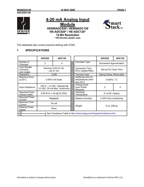
<strong>MAN0235</strong>-<strong>09</strong> 10 NOV <strong>20</strong>06 PAGE 1<br />
ADC0<strong>20</strong>/1<strong>20</strong><br />
4-<strong>20</strong> <strong>mA</strong> <strong>Analog</strong> <strong>Input</strong><br />
<strong>Module</strong><br />
HE800ADC0<strong>20</strong> / HE800ADC1<strong>20</strong><br />
HE-ADC0<strong>20</strong>* / HE-ADC1<strong>20</strong>*<br />
12-Bit Resolution<br />
* HE-denotes plastic case.<br />
This datasheet also covers products starting with IC300.<br />
1 SPECIFICATIONS<br />
ADC0<strong>20</strong> ADC1<strong>20</strong> ADC0<strong>20</strong> ADC1<strong>20</strong><br />
Number of<br />
Converter Type<br />
2 4<br />
Channels<br />
Successive Approximation<br />
<strong>Input</strong> Ranges<br />
Nominal: 0-<strong>20</strong>.47 <strong>mA</strong>,<br />
Conversion Time<br />
(including<br />
±<strong>20</strong>.47 <strong>mA</strong>,<br />
(PLC Update Rate)<br />
over-range)<br />
Set by PLC Scan Time<br />
Resolution 12-Bit Terminal Type Spring Clamp, Removable<br />
Maximum Error<br />
at 25°C<br />
0.05% Full Scale<br />
Additional error for<br />
temperatures other<br />
0.005% / °C<br />
<strong>Input</strong> Impedance<br />
Required Power<br />
(Steady State)<br />
Required Power<br />
(Inrush)<br />
Maximum Over-<br />
Current<br />
External Power<br />
Supply<br />
CE<br />
UL<br />
100 Ω < 12 VDC, Clamped @<br />
12 VDC, 35 <strong>mA</strong> Max. Continuous<br />
0.<strong>09</strong> W (4.1 <strong>mA</strong> @ 24 VDC)<br />
than 25°C<br />
<strong>Analog</strong> <strong>Input</strong>s<br />
<strong>Input</strong> Points<br />
Required<br />
Operating<br />
Temperature<br />
2 4<br />
0° to 60° Celsius<br />
Negligible Relative Humidity 5–95% Non-condensing<br />
35 <strong>mA</strong><br />
None<br />
Weight 9 oz. (256 g)<br />
See Compliance Table at http://www.heapg.com/Support/compliance.htm<br />
Information is subject to change without notice.<br />
SmartStack is a trademark of <strong>Horner</strong> <strong>APG</strong>, LLC.
PAGE 2 10 NOV <strong>20</strong>06 <strong>MAN0235</strong>-<strong>09</strong><br />
ADC0<strong>20</strong>/1<strong>20</strong><br />
2 WIRING<br />
*<br />
4-<strong>20</strong><strong>mA</strong><br />
TRANSMITTER<br />
4-<strong>20</strong><strong>mA</strong><br />
TRANSMITTER<br />
4-<strong>20</strong><strong>mA</strong><br />
TRANSMITTER<br />
4-<strong>20</strong><strong>mA</strong><br />
TRANSMITTER<br />
LOOP<br />
POWER<br />
LOOP<br />
POWER<br />
LOOP<br />
POWER<br />
LOOP<br />
POWER<br />
1+<br />
1-<br />
2+<br />
2-<br />
3+<br />
3-<br />
4+<br />
4-<br />
001ADC002<br />
*<br />
OCS Bottom View – Shows<br />
Corresponding I/O Pin<br />
Pin # ADC1<strong>20</strong> ADC0<strong>20</strong><br />
1+ Channel 1+ Channel 1+<br />
1- Common Common<br />
Shield Shield<br />
2+ Channel 2+ Channel 2+<br />
2- Common Common<br />
Shield Shield<br />
3+ Channel 3+<br />
3- Common<br />
Shield<br />
4+ Channel 4+<br />
4- Common<br />
Shield<br />
3 INTERNAL CIRCUIT SCHEMATIC<br />
I/O Connector<br />
SmartStack<br />
Field<br />
Side<br />
1+<br />
1- Gnd<br />
To<br />
100Ω<br />
Shield<br />
Controller<br />
Information is subject to change without notice.<br />
SmartStack is a trademark of <strong>Horner</strong> <strong>APG</strong>, LLC.
<strong>MAN0235</strong>-<strong>09</strong> 10 NOV <strong>20</strong>06 PAGE 3<br />
ADC0<strong>20</strong>/1<strong>20</strong><br />
4 CONFIGURATION<br />
Note: The status of the I/O can be monitored in Cscape Software.<br />
Preliminary configuration procedures that apply to SmartStack <strong>Module</strong>s are contained in the hardware<br />
manual of the controller you are using. Refer to the Additional References section in this data sheet for a<br />
listing of hardware manuals.<br />
Selecting the I/O Map tab provides information about the I/O registers, which are assigned to a specific<br />
SmartStack <strong>Module</strong> and where the module is located in the point map. The I/O Map is determined by<br />
the model number and location within the SmartStack. The I/O Map is not edited by the user.<br />
<strong>Module</strong> Setup Tab<br />
a) <strong>Input</strong> range for each channel may be selected independently.<br />
b) Filter Constant sets the level of digital filtering according to the following chart.<br />
0 1 2 3 4 5 6 7<br />
Filter<br />
Constant<br />
%Complete [ ]<br />
100<br />
90<br />
80<br />
70<br />
60<br />
50<br />
40<br />
30<br />
<strong>20</strong><br />
10<br />
0<br />
0<br />
<strong>20</strong><br />
40 60 80<br />
100<br />
Scans<br />
Digital Filtering: The illustration above demonstrates the effect of digital filtering (set with Filter Constant)<br />
on module response to a temperature change.<br />
Information is subject to change without notice.<br />
SmartStack is a trademark of <strong>Horner</strong> <strong>APG</strong>, LLC.
PAGE 4 10 NOV <strong>20</strong>06 <strong>MAN0235</strong>-<strong>09</strong><br />
ADC0<strong>20</strong>/1<strong>20</strong><br />
5 INPUT CONVERSION FACTOR<br />
The following table describes how real-world inputs are scaled into the controller. Given a known input<br />
current, the data value is configured by using the conversion factor from the table. The following formula<br />
is used: Data = <strong>Input</strong> Current (<strong>mA</strong>) / Conversion Factor<br />
Example: The user selects a current range of 0 to +<strong>20</strong> <strong>mA</strong>:<br />
1) The known input current is 14 <strong>mA</strong>..<br />
2) Using the table, the conversion factor for the current range of 0 to +<strong>20</strong> VDC is 0.000625.<br />
3) To determine the data value, the formula is used:<br />
Data = <strong>Input</strong> Current (<strong>mA</strong>) / Conversion Factor<br />
22400 = 14 <strong>mA</strong> / 0.000625<br />
Conversion of Real-World <strong>Input</strong>s into Controller<br />
Selected Current<br />
Range<br />
0 to +<strong>20</strong> <strong>mA</strong><br />
-<strong>20</strong> to +<strong>20</strong> <strong>mA</strong><br />
<strong>Input</strong> Current (<strong>mA</strong>) Data Conversion Factor<br />
+<strong>20</strong>.47 32752<br />
+<strong>20</strong>.00 3<strong>20</strong>00<br />
0.000625<br />
0 0<br />
-<strong>20</strong>.00 -3<strong>20</strong>00<br />
-<strong>20</strong>.47 -32752<br />
0.000625<br />
Information is subject to change without notice.<br />
SmartStack is a trademark of <strong>Horner</strong> <strong>APG</strong>, LLC.
<strong>MAN0235</strong>-<strong>09</strong> 10 NOV <strong>20</strong>06 PAGE 5<br />
ADC0<strong>20</strong>/1<strong>20</strong><br />
6 INSTALLATION / SAFETY<br />
Warning: Remove power from the OCS controller, CAN port, and any peripheral equipment<br />
connected to this local system before adding or replacing this or any module.<br />
a) All applicable codes and standards should be followed in the installation of this product.<br />
b) Shielded, twisted-pair wiring should be used for best performance.<br />
c) Shields may be terminated at the module terminal strip.<br />
d) In severe applications, shields should be tied directly to the ground block within the panel.<br />
e) Use the following wire type or equivalent:<br />
Belden 8441.<br />
For detailed installation and a handy checklist that covers panel box layout requirements and minimum<br />
clearances, refer to the hardware manual of the controller you are using. (See the Additional References<br />
section in this document.).<br />
When found on the product, the following symbols specify:<br />
Warning: Consult user documentation.<br />
Warning: Electrical Shock Hazard.<br />
WARNING: To avoid the risk of electric shock or burns, always connect the safety (or earth)<br />
ground before making any other connections.<br />
WARNING: To reduce the risk of fire, electrical shock, or physical injury it is strongly<br />
recommended to fuse the voltage measurement inputs. Be sure to locate fuses as close to the<br />
source as possible.<br />
WARNING: Replace fuse with the same type and rating to provide protection against risk of fire<br />
and shock hazards.<br />
WARNING: In the event of repeated failure, do not replace the fuse again as a repeated failure<br />
indicates a defective condition that will not clear by replacing the fuse.<br />
WARNING: Only qualified electrical personnel familiar with the construction and operation of<br />
this equipment and the hazards involved should install, adjust, operate, or service this<br />
equipment. Read and understand this manual and other applicable manuals in their entirety<br />
before proceeding. Failure to observe this precaution could result in severe bodily injury or loss<br />
of life.<br />
Information is subject to change without notice.<br />
SmartStack is a trademark of <strong>Horner</strong> <strong>APG</strong>, LLC.
PAGE 6 10 NOV <strong>20</strong>06 <strong>MAN0235</strong>-<strong>09</strong><br />
ADC0<strong>20</strong>/1<strong>20</strong><br />
For detailed installation and a handy checklist that covers panel box layout requirements and minimum<br />
clearances, refer to the hardware manual of the controller you are using. (See the Additional References<br />
section in this document.):<br />
• All applicable codes and standards need to be followed in the installation of this product.<br />
• For I/O wiring (discrete), use the following wire type or equivalent: Belden 9918, 18 AWG or<br />
larger.<br />
Adhere to the following safety precautions whenever any type of connection is made to the module.<br />
• Connect the green safety (earth) ground first before making any other connections.<br />
• When connecting to electric circuits or pulse-initiating equipment, open their related breakers.<br />
Do not make connections to live power lines.<br />
• Make connections to the module first; then connect to the circuit to be monitored.<br />
• Route power wires in a safe manner in accordance with good practice and local codes.<br />
• Wear proper personal protective equipment including safety glasses and insulated gloves<br />
when making connections to power circuits.<br />
• Ensure hands, shoes, and floor are dry before making any connection to a power line.<br />
• Make sure the unit is turned OFF before making connection to terminals. Make sure all<br />
circuits are de-energized before making connections.<br />
• Before each use, inspect all cables for breaks or cracks in the insulation. Replace<br />
immediately if defective.<br />
Information is subject to change without notice.<br />
SmartStack is a trademark of <strong>Horner</strong> <strong>APG</strong>, LLC.
<strong>MAN0235</strong>-<strong>09</strong> 10 NOV <strong>20</strong>06 PAGE 7<br />
ADC0<strong>20</strong>/1<strong>20</strong><br />
7 ADDITIONAL REFERENCES<br />
The following information serves as a general listing of <strong>Horner</strong> controller products and other references of<br />
interest and their corresponding manual numbers. Visit our website listed in the Technical Support section<br />
to obtain user documentation and updates.<br />
Note: This list is not intended for users to determine which products are appropriate for their<br />
application; controller products differ in the features that they support. If assistance is required,<br />
see the Technical Support section in this document.<br />
Controller<br />
XLE Series (e.g., HE-XExxx)<br />
QX Series (e.g., HE-QXxxx)<br />
NX Series (e.g., HE-NXxxx)<br />
LX Series (e.g., LX-xxx; also covers RCS116)<br />
Color Touch OCS (e.g., OCSxxx)<br />
OCS (Operator Control Station) (e.g., OCS1xx / 2xx; Graphic<br />
OCS250)<br />
Remote Control Station (e.g., RCS2x0)<br />
MiniOCS (e.g., HE500OCSxxx, HE500RCSxxx)<br />
CAN Networks<br />
Cscape Programming and Reference<br />
Wiring Accessories and Spare Parts Manual<br />
DeviceNet Implementation<br />
Wiring Accessories and Spare Parts Manual<br />
Other Useful References<br />
Manual Number<br />
MAN0805<br />
MAN0798<br />
MAN0781<br />
MAN0755<br />
MAN0465<br />
MAN0227<br />
MAN0305<br />
MAN0799<br />
MAN0313<br />
MAN0347<br />
SUP0326<br />
MAN0347<br />
8 TECHNICAL SUPPORT<br />
For assistance and manual up-dates, contact Technical Support at the following locations:<br />
North America:+<br />
(317) 916-4274<br />
www.heapg.com<br />
Europe:<br />
(+) 353-21-4321-266<br />
www.horner-apg.com<br />
Information is subject to change without notice.<br />
SmartStack is a trademark of <strong>Horner</strong> <strong>APG</strong>, LLC.
PAGE 8 10 NOV <strong>20</strong>06 <strong>MAN0235</strong>-<strong>09</strong><br />
ADC0<strong>20</strong>/1<strong>20</strong><br />
NOTES<br />
Information is subject to change without notice.<br />
SmartStack is a trademark of <strong>Horner</strong> <strong>APG</strong>, LLC.


