

05-6193A01-A - GE Digital Energy
05-6193A01-A - GE Digital Energy
05-6193A01-A - GE Digital Energy

Create successful ePaper yourself
Turn your PDF publications into a flip-book with our unique Google optimized e-Paper software.
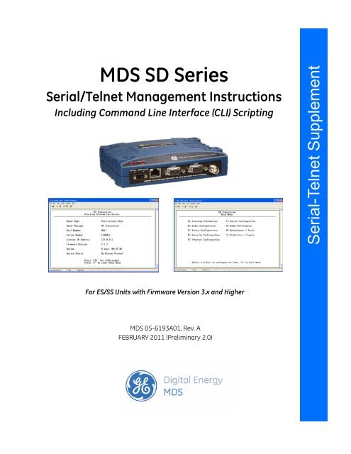
MDS SD SeriesSerial/Telnet Management InstructionsIncluding Command Line Interface (CLI) ScriptingInstallation Serial-Telnet and Operation Supplement GuideFor ES/SS Units with Firmware Version 3.x and HigherMDS <strong>05</strong>-<strong>6193A01</strong>, Rev. AFEBRUARY 2011 (Preliminary 2.0)
All <strong>GE</strong> MDS user guides are available online at www.gemds.com
TABLE OF CONTENTS1.0 INTRODUCTION ................................................................................................................................. 12.0 CONNECTING A PC............................................................................................................................ 12.1 Differences Between Serial & Telnet ..............................................................................................................1Connecting a PC & Setting Basic Parameters ..................................................................................................13.0 USING THE MENU SYSTEM............................................................................................................ 53.1 Menu Access ...................................................................................................................................................53.2 Menu Structure ................................................................................................................................................63.3 Menu Navigation .............................................................................................................................................63.4 Logging Out of the Menu System ...................................................................................................................63.5 Task-Oriented Menu Chart ..............................................................................................................................83.6 Using the Menu System—Common Tasks ...................................................................................................12Viewing Status and Performance Information ................................................................................................123.7 View/Set Radio (RF) Operating Parameters .................................................................................................18RF Output Power Setting ................................................................................................................................18Modem Type Setting.......................................................................................................................................18RX and TX Frequencies..................................................................................................................................19Soft-Carrier Dekey Setting..............................................................................................................................20RX and TX Time-Out Settings .......................................................................................................................20Datakey Setting...............................................................................................................................................22RTSkey Setting ...............................................................................................................................................22Push-To-Talk Delay ........................................................................................................................................22Clear-to-Send Delay........................................................................................................................................22Switched Carrier Setting (B Modems Only)...................................................................................................23RX Signal Attenuation....................................................................................................................................23Listen Before Transmit (LBT) Feature ...........................................................................................................23View Received Signal Strength (RSSI)...........................................................................................................263.8 View/Set Device Configuration ....................................................................................................................26Viewing Serial Number and Version Information...........................................................................................26Setting Owner Name/Message........................................................................................................................28Enabling/Disabling Sleep Mode .....................................................................................................................29Setting Serial COM LED Mode......................................................................................................................30Viewing/Setting Radio Mode..........................................................................................................................30Setting the User Interface Type.......................................................................................................................30Configuring the Radio to Support Multiple Hosts(Only if operating in Packet mode without MAC) .........................................................................................31Configuring Packet Settings............................................................................................................................32Media Access Control Settings(Packet with MAC operation) .........................................................................................................................33Configuring Diagnostic Settings.....................................................................................................................353.9 Security Settings ............................................................................................................................................36Setting a Password ..........................................................................................................................................37MDS <strong>05</strong>-4846A01, Rev. D SD Series Technical Manual i
Setting the AES Wireless Security Parameters...............................................................................................38Menu ...............................................................................................................................................................393.10 Ethernet Configuration ................................................................................................................................40Configuring the IP Settings.............................................................................................................................41Ethernet Bridge Configuration........................................................................................................................42Ethernet Port Configuration ............................................................................................................................44IP Payload 1/2/3 Configuration Settings.........................................................................................................45IP Payload Configuration—Menu Selections .................................................................................................47Terminal Server COM1/2 Configuration ........................................................................................................49VLAN Configuration ......................................................................................................................................52IP2 Configuration............................................................................................................................................553.11 Serial Configuration ....................................................................................................................................56Configuring COM1 Settings ...........................................................................................................................57Configuring COM2 Settings ...........................................................................................................................583.12 Maintenance & Diagnostic Tests ................................................................................................................60Managing Configuration Files ........................................................................................................................60Performing Remote Management ...................................................................................................................63Performing Radio Tests...................................................................................................................................64Reprogramming the Transceiver.....................................................................................................................68Remote Reprogramming.................................................................................................................................70Conducting a PING Test .................................................................................................................................71Conducting a Linktest .....................................................................................................................................71Viewing Enabled Features ..............................................................................................................................72Viewing Active Alarms/Events.......................................................................................................................73Configuring the Alarm Signal.........................................................................................................................733.13 Event Codes .................................................................................................................................................75Checking for Alarms.......................................................................................................................................76Status and Informational Events .....................................................................................................................76Event Code Definitions...................................................................................................................................76Viewing I/O Statistics .....................................................................................................................................773.14 Performing Network-Wide Remote Diagnostics ........................................................................................793.15 Over-the-Air Firmware Upgrades ...............................................................................................................80Intrusive vs. Passive (Non-Intrusive) Mode ...................................................................................................80OTA Reprogramming Overview.....................................................................................................................82Cancelling OTA Reprogramming ...................................................................................................................82Error Conditions/Recovery .............................................................................................................................83Execution and screen Examples......................................................................................................................833.16 COM1 Operating Modes .............................................................................................................................85Options ............................................................................................................................................................85Changing COM1 Modes .................................................................................................................................853.17 Upgrading Firmware (Local Method) ........................................................................................................87Upgrading Firmware via TFTP (LAN port) ...................................................................................................87Upgrading Firmware (via Serial Port) ............................................................................................................91APPENDIX-A CLI Scripting Interface .........................................................................................92Entering Commands........................................................................................................................................92Detailed Command Descriptions ....................................................................................................................94ii SD Series Technical Manual MDS <strong>05</strong>-4846A01, Rev. D
Copyright and TrademarkThis manual and all software described herein is protected by Copyright: 2011 <strong>GE</strong> MDS, LLC. Allrights reserved. <strong>GE</strong> MDS, LLC reserves its right to correct any errors and omissions in this publication.Modbus ® is a registered trademark of Schneider Electric Corporation. All other trademarksand product names are the property of their respective owners.Quality Policy StatementWe, the employees of <strong>GE</strong> MDS, are committed to understanding and exceeding our customer’sneeds and expectations.• We appreciate our customers’ patronage. They are our business.• We promise to serve them and anticipate their needs.• We are committed to providing solutions that are cost effective, innovative and reliable, withconsistently high levels of quality.We are committed to the continuous improvement of all of our systems and processes, to improveproduct quality and increase customer satisfaction.Manual Revision and AccuracyThis manual was prepared to cover a specific version of firmware code. Accordingly, some screensand features may differ from the actual unit you are working with. While every reasonable efforthas been made to ensure the accuracy of this publication, product improvements may also result inminor differences between the manual and the product shipped to you. If you have additional questionsor need an exact specification for a product, please contact <strong>GE</strong> MDS using the information atthe back of this guide. In addition, manual updates can often be found on our web site atwww.gemds.com.Related ManualThis manual is furnished as a supplement to the main product manual for the SD Transceiver. Priorto operation, refer to the MDS SD Series Technical Manual, <strong>05</strong>-4846A01 for operational and safetywarnings, installation instructions, and other related information.MDS <strong>05</strong>-4846A01, Rev. D SD Series Technical Manual iii
iv SD Series Technical Manual MDS <strong>05</strong>-4846A01, Rev. D
1.0 INTRODUCTIONThis document is a supplement to the SD Series Technical Manual(<strong>05</strong>-4846A01). It explains how to configure and manage the SD transceiverusing Serial or Telnet methods from a connected PC.Transceiver firmware version 4.0 and higher provides a web-based toolknown as a Device Manager, which offers an intuitive, graphicalapproach to transceiver management. While this method is preferred formost users, some may be running an earlier version of the firmware, ormay wish to use an alternative management method in automated controlsystems. This guide covers connection, log-in, and management ofthe radio via Serial or Telnet control methods.2.0 CONNECTING A PC2.1 Differences Between Serial & TelnetSerial and Telnet both present identical menu screens, but the method ofaccess is different for each. Serial involves an RS-232 serial connectionfrom a PC to one of the radio’s DB-9 ports (typically COM1). Telnetuses an Ethernet PC connection to the radio’s LAN port. Maximum recommendedcable length for a serial connection is 50 feet (15 meters).Telnet can be connected to the radio from any network point that hasconnectivity with the management PC, including remotely, over theInternet.The focus of these instructions is on Serial access, but Telnet may alsobe used by following these additional points, which replace Steps 1-3below:• Connect to the radio with a PC that is on the same IP network asthe transceiver. Launch a Telnet program, and connect to theradio using its programmed IP address.• The default IP address for an SD is 192.168.1.1. If you do notknow the IP address of the radio, follow the serial configurationinstructions below, where you can determine the radio's addressand continue configuration of the radio.Connecting a PC & Setting Basic ParametersFollow these steps to configure the transceiver for its first use:1. Connect a PC to the radio’s COM1 serial port as shown in Figure 1.(Maximum recommended cable length: 50 ft./15 m)NOTE:Not all PCs include a serial port. If one is not available, a USB port may beused, along with a USB-to-Serial adapter (with appropriate driver software).Adapters are available from many manufacturers, including <strong>GE</strong>MDS.MDS <strong>05</strong>-<strong>6193A01</strong>, Rev. A SD Series Serial-Telnet Supplement 1
NOTE:If COM1 has been configured to boot into data mode, pressing ENTERwithin 10 seconds of boot-up switches it into console (management) mode.Console mode is required for the following steps.2. Launch a terminal communications program, such as HyperTerminal(included with many Windows ® -based PCs) with the followingcommunication parameters: 8 bits, no parity, one stop bit(8N1), flow control disabled, VT100 emulation. The radio’s COM1port automatically determines the connected baud rate (within therange of 1200–115200 bps). The preferred baud rate is 9600 bps.To use the autobaud feature, press the ENTER key several times athalf-second intervals to lock into the correct baud rate.Invisible place holderTransceiverPC Running Terminal SessionDB-9M to COM1 PortFigure 1. PC Connection to Transceiver3. Press the ESCAPE key followed by a series of ENTER key presses (athalf-second intervals) to receive the Login: prompt. This indicates thatthe radio is ready to receive commands. (If a “>” or “>>” symbol isseen, the radio is set to command line mode. Enter Menu to leavecommand line.)4. At the Login: prompt, enter admin (lower case) and press ENTER .NOTE:Passwords are case sensitive and may use up to 13 alpha-numeric characters.Do not use punctuation mark characters.5. If no password has been previously set, enter the default password(admin) and press ENTER ; Otherwise, enter the saved password atthe Password: prompt. (Before placing the unit in final service, it isrecommended that the default password be changed using the SecurityConfiguration Menu.)6. After successful login, the Starting Information Screen appears(Figure 2), showing summary information about the radio. Thisscreen is read-only, but some of the fields change based on user-supplieddata at other menu screens.2 SD Series Serial-Telnet Supplement MDS <strong>05</strong>-<strong>6193A01</strong>, Rev. A
NOTE:TX and RX frequencies may not be set when the radio is shipped from thefactory, depending on ordering options. If frequencies have not been set,Major Alarms Present will be displayed on the Starting Information Screenand the PWR led will flash. These will be cleared after the frequencies areset. In all cases, users should verify that the frequencies are properly setaccording to the station license.Figure 2. Starting Information Screen(First screen displayed upon login)7. Press G to access the Main Menu (Figure 3). This is the gateway toall settable parameters of the radio. Menu selections are made bypressing the letter shown to the left of a item name.Figure 3. Main Menu Screen(Entry point for all transceiver menus)MDS <strong>05</strong>-<strong>6193A01</strong>, Rev. A SD Series Serial-Telnet Supplement 3
8. Select Radio Configuration from the Main Menu and then select BasicSettings. The screen shown in Figure 4 appears. Review these basicsettings to determine if they are appropriate for your system.• The default RF Output Power default setting is 37 dBm (5 watts), butyou may wish to set it lower if full power is not required for yoursystem. MDS SD2 power is limited to 2 watts in Band B (220-222MHz) to meet regulatory requirements.• The Modem Type default setting is Modem 9600. This corresponds to9600 bps over-the-air data speed in a 12.5 kHz channel. Otherselections are possible by selecting the item and using the spacebarto cycle through the available choices. (A chart of modemselections and their associated bandwidths is provided in Table 2on Page 18.)• The RX (receive) and TX (transmit) frequencies may be unprogrammedwhen shipped from the factory. Set the frequencies bypressing the letter to the left of RX and TX, and entering the correctfrequencies in MHz (xxx.xxxxx) as authorized by your stationlicense. Press ENTER . (If no frequency is set, the value will indicateNone and the power LED will flash as a reminder to set thefrequency.)NOTE:Operation on exact multiples of 25 MHz is not supported by the SD4 transceiver(i.e., 400, 425, 450, 475, and 500 MHz).Figure 4. Radio Configuration>>Basic Settings Menu9. When done, exit the Basic Settings Menu by pressing thekey, which returns you to the Main Menu. Check the other menuscreens to review the default settings and make any necessarychanges.ESCAPEThis completes the initial setup and configuration of the radio via Serial/Telnetconnection.4 SD Series Serial-Telnet Supplement MDS <strong>05</strong>-<strong>6193A01</strong>, Rev. A
3.0 USING THE MENU SYSTEMThis section covers the management and programming tasks that can beperformed with the transceiver’s built-in menu system. A top level viewof the menu tree is shown, as well as a chart listing commonly-neededtasks and the appropriate menu(s) to refer to.No attempt has been made to show every possible submenu of the transceiverhere. The objective is to explain how to locate the proper menufor a specific task and what selections to use once you are there. A completelisting of all menu screens is provided in the Menu Reference sectionat the back of this manual.NOTE: This manual assumes menu-based control as the primarymethod of managing the radio. To return to menu control fromother programming modes, enter the command menu.For specialized applications, a command line interface isdescribed in “APPENDIX-A CLI Scripting Interface” onPage 91.3.1 Menu AccessThe section titled “Connecting a PC & Setting Basic Parameters” onPage 1 explains how to log into the menu system and access the MainMenu (Figure 5). The Main Menu is the entry point for all transceiverfunctions. Review the login information if you have not yet establisheda PC connection with the radio.Figure 5. Main Menu Screen(Entry point for all transceiver menus)MDS <strong>05</strong>-<strong>6193A01</strong>, Rev. A SD Series Serial-Telnet Supplement 5
3.2 Menu StructureThe transceiver menus are arranged in a hierarchal format based on themajor tasks that can be performed. An overall view of the menu systemis shown in Figure 6.3.3 Menu NavigationStarting InformationScreenUsing the Main MenuMaking Menu ChangesWhen you first log in to the menu system, the Starting InformationScreen appears with a summary of current operating conditions.Pressing G from this screen takes you to the Main Menu, which is theentry point for all transceiver menus.Individual menus are selected from the Main Menu by typing the lettershown to the left of the entry. When the chosen menu appears, settingsmay be viewed or changed as applicable. In most cases, pressing theESCAPE key moves the screen back one level in the menu tree.When you arrive at a menu with user-controllable parameters, you selectmenu items by pressing the associated letter on the keyboard. If there isa user-definable value, the field clears to the right of the menu item anda flashing cursor appears. you then type the value you wish to use.Follow this action by pressing the ENTER key to apply the change(s). Ifyou make a mistake or change your mind before pressing the ENTER key,simply press ESCAPE to restore the previous values.In some menus, when you type a letter to select a parameter, a messageappears at the bottom of the screen stating that the available choices maybe cycled by pressing your keyboard’s spacebar. When the desiredoption appears, press the ENTER key to apply the selection. If you makea mistake or change your mind before pressing the ENTER key, simplypress ESCAPE to restore the previous values.3.4 Logging Out of the Menu SystemTo exit the menu system, press Q from any menu. The menu session willbe terminated.NOTE: To maintain security, it is best to log-out of the menu systemas soon as you are done working with it. If you do not log out,the session automatically ends after 10 minutes of inactivity.If the activity timer expires when the diagnostic link is set toON, no prompt will be visible for logging back in to the menusystem. If this happens, press the ENTER key a few times athalf-second intervals to obtain the login prompt.6 SD Series Serial-Telnet Supplement MDS <strong>05</strong>-<strong>6193A01</strong>, Rev. A
Invisible place holderMENU SYSTEMOverviewMAIN MENUStarting Info ScreenRadioConfigurationDeviceConfigurationSecurityConfigurationEthernetConfigurationSerialConfigurationRadioPerformanceBasic SettingsAdvanced SettingsDevice InfoDevice SettingsLogin PasswordsWireless SecurityIP ConfigurationBridge ConfigurationCOM1 Settings Measured RF PowerCOM2 Settings Signal to NoiseLBT SettingsMultihost Settings Device Security Ethernet Port Config.RSSIPacket SettingsIP1/2/3 Payload Config.DC VoltageMedia Access ControlTerm. Srvr. COM1/2 Config.TemperatureDiagnostic SettingsVLAN ConfigurationNOTES• Chart shows top-level view only. See specific menu for details.• Not all menu items are user-configurable; some are read-only.• PC Spacebar is used to make some menu selections.IP2 ConfigurationStatistics/EventsAlarms/EventsAlarm Signal Config.Event LogI/O StatisticsEthernet StatisticsMaintenance/ToolsConfig. ManagementRadio TestVersionLocal ReprogramRemote ProgramPingLinktestRemote ManagementAuthorization CodesFigure 6. Menu System OverviewMDS <strong>05</strong>-<strong>6193A01</strong>, Rev. A SD Series Serial-Telnet Supplement 7
3.5 Task-Oriented Menu ChartTable 1 is a task-oriented listing of user and maintenance tasks. To usethe table, find the task you wish to perform, and then refer to the farright-hand column for the specific menu(s) to use. Additional coverageof menu tasks is provided in “Using the Menu System—CommonTasks” on Page 12 which immediately follows this table.Table 1. Menu Selection ChartTaskCategoryView OverallStatus & PerformanceInformationIf you wish to...View top-level unit information (OwnerName/Message, Unit Number, IP Address, SerialNo., Firmware version, Run time, Alarm presence,etc.)View Radio Performance data (Power Output,Signal-to-Noise Ratio, Received Signal Strength, DCInput voltage, operating temperature)View Serial No., Model 1 (hardware), Model 2(software) version, Firmware Version, Build DateView Bootloader version information, ActiveFirmware Image, Firmware Version levelView Alarm/Event information, I/O Statistics,Ethernet StatisticsRefer to thisMenu>>Submenu(s)Starting Information Screen(See Figure 7 on Page 13)Radio Performance(See Figure 8 on Page 13)Device Configuration>>Device Info(See Figure 9 on Page 14)Maintenance/Tools>>Version(See Figure 10 on Page 14)Statistics/Events>>Alarms/EventsEvent LogI/O StatisticsEthernet Statistics(See Figure 11 on Page 15 &following submenus)8 SD Series Serial-Telnet Supplement MDS <strong>05</strong>-<strong>6193A01</strong>, Rev. A
Table 1. Menu Selection Chart (Continued)TaskCategoryView/Set Radio (RF)Operating ParametersView/Set DeviceConfigurationSecuritySettingsIf you wish to...Set RF Output Power, Modem Type, RX/TXFrequencyView/Set Soft-Carrier Dekey status, RX/TXTime-Out optionsData-Key and RTS-Key settings (ON/OFF)Push-to-Talk/Clear-to-Send Delay times (ms)Automatic Frequency Correction (AFC) settingSwitched Carrier ON/OFF settingConfigure Listen-Before-Transmit (LBT) collisionavoidanceView Received Signal Strength (RSSI) levelKey the radio transmitter, view power outputMonitor local radio emissions for possibleinterferenceView Serial No., Model 1 (hardware), Model 2(software) version, Firmware Version, Build DateSet Owner Name/Message, enable/disable SleepMode, set COM LED mode, Radio ModeConfigure radio to support multiple hosts on serialand Ethernet ports.Configure time delays to identify packets on serialportsConfigure Unit ID and/or DLINK diagnosticssettingsSet Password for radioSet Device Security (enable/disable local loginrequirement, enable/disable Telnet access)Set Wireless Security parameters (Encryption on/off,phrase, DLINK Security on/off)Refer to thisMenu>>Submenu(s)Radio Configuration>>Basic Settings(See Figure 16 on Page 18)Radio Configuration>>Advanced Settings(See Figure 17 on Page 20)Radio Configuration>>Advanced Settings(See Figure 17 on Page 20)Radio Configuration>>Advanced Settings(See Figure 17 on Page 20)Radio Configuration>>Advanced Settings(See Figure 17 on Page 20)Radio Configuration>>Advanced Settings(See Figure 17 on Page 20)Radio Configuration>>LBT Settings(See Figure 18 on Page 23)Radio Performance(See Figure 19 on Page 25)Radio Test>>RF Keying Test(See Figure 49 on Page 65)Radio Test>>Spectrum(See Figure 50 on Page 66)Device Configuration>>Device Info(See Figure 21 on Page 26)Device Configuration>>Device Settings(See Figure 23 on Page 28)Device Configuration>>Multihost Settings(See Figure 24 on Page 31)Device Configuration>>Packet Settings(See Figure 25 on Page 31)Device Configuration>>Diagnostic Settings(See Figure 27 on Page 34)Security Configuration>>Password(See Figure 29 on Page 36)Device Security Menu(See Figure 31 on Page 38)Security Configuration>>Wireless Security(See Figure 30 on Page 37)MDS <strong>05</strong>-<strong>6193A01</strong>, Rev. A SD Series Serial-Telnet Supplement 9
Table 1. Menu Selection Chart (Continued)TaskCategoryEthernet PortConfigurationSerial PortConfigurationIf you wish to...Configure the IP settings (Static IP Address, Static IPNetmask, Static Default Gateway, DHCPenable/disable, Virtual Radio Channels–VRCs)Configure Ethernet BridgingConfigure the Ethernet Port settings (Enable/disableport, set mode, Local IP Port, Destination IP Address,Destination IP Port, TCP Keepalive time)Configure COM1 settings (Startup mode, Data BaudRate, Data format, Virtual Radio Channels–VRCs)Configure COM2 settings (Mode, Baud Rate,Format, Buffer on/off, Device Type, Virtual RadioChannels–VRCs)Refer to thisMenu>>Submenu(s)Ethernet Configuration>>IP Configuration(See Figure 33 on Page 40)Ethernet Configuration>>Bridge Configuration(See Figure 34 on Page 42)Ethernet Configuration>>Ethernet Data Port(See Figure 36 on Page 45)Serial Configuration>>COM1 Port Settings(See Figure 42 on Page 56)Serial Configuration>>COM2 Port Settings(See Figure 43 on Page 58)10 SD Series Serial-Telnet Supplement MDS <strong>05</strong>-<strong>6193A01</strong>, Rev. A
Table 1. Menu Selection Chart (Continued)TaskCategoryTransceiver Maintenance and Diagnostic TestsIf you wish to...View Radio Performance data (Power Output,Signal-to-Noise Ratio, Received Signal Strength, DCInput voltage, operating temperature)Perform radio tests (Radio Keying, run SpectrumAnalyzer, run RTU Simulator)View Bootloader version information, ActiveFirmware Image, Firmware Version levelLocally Reprogram the Transceiver via Serial orTFTP transferBroadcast Remote Configuration settings to allradios in the networkWork with Configuration Files...–Restore Factory default configuration–Save/restore user configuration–View/restore key configuration parameters–Save/load key configuration parameters using filetransfer (TFTP)Start radio network reprogramming (and monitorprogress)Perform Ethernet PING to local Ethernet hostTest communications to specific Remote radioEnter a Factory Authorization code, or view currentlyenabled featuresView active Alarms/EventsView logged EventsAdjust alarm signal output (active high/low)View I/O Statistics for COM1, COM2, Ethernet Port,Remote Programming, Ethernet Interface, Data LinkLayer, and MAC)Refer to thisMenu>>Submenu(s)Radio Performance(See Figure 19 on Page 25)Maintenance/Tools>>Radio Test(See Figure 48 on Page 64)Maintenance/Tools>>Version(See Figure 10 on Page 14)Maintenance/Tools>>Local Reprogram(See Figure 72 on Page 89)Maintenance/Tools>>Remote Reprogram Menu(See Figure 66 on Page 83)Maintenance/Tools>>Configuration Management(See Figure 44 on Page 60)Maintenance/Tools>>Remote Reprogram(See Figure 66 on Page 83)Maintenance/Tools>>PING(See Figure 56 on Page 70)Maintenance/Tools>>Linktest(See Figure 57 on Page 70)Maintenance/Tools>>Authorization Codes(See Figure 58 on Page 71)Statistics/Events Menu>>Alarms/Events(See Figure 59 on Page 72)Statistics/Events Menu>>Event Log(See Figure 13 on Page 16)Statistics/Events Menu>>Alarm Signal Config.(See Figure 60 on Page 74)Statistics/Events Menu>>I/O Statistics(See Figure 14 on Page 16)MDS <strong>05</strong>-<strong>6193A01</strong>, Rev. A SD Series Serial-Telnet Supplement 11
3.6 Using the Menu System—Common TasksThe transceiver is designed for rapid installation with a minimumnumber of menu configuration steps. In many cases, only the receive(RX) and transmit (TX) frequencies need to be set to begin basic operation.Nevertheless, proper use of the menu system allows the transceiverto be tailored for optimal performance, and allows several key statuspoints to be observed in real time.This section describes common tasks performed with the menu system.Some of these might be performed at the time of installation, whileothers are intended for later management, programming or maintenanceactivities. For easy reference, the tasks described here are presented inthe same order as those listed in Table 1.Viewing Status and Performance InformationPerhaps the most common use for the menu system is to check theoverall health and operating status of the radio. The arrangement of themenu system makes it easy to view this information in several differentways. Listed below are the key menus where status and performanceinformation are displayed.Starting InformationScreenWhen you first log in to the menu system, the Starting Information Screenappears (Figure 7). This screen is read-only, and provides key informationabout the current operating conditions of the transceiver. Whilechanges cannot be made here, some of the entries (such as OwnerName/Message, Unit Number, and Current IP Address) are determined by informationentered on other screens. To go to the Main Menu from here, pressG.NOTE: Pressing ESC at the Starting Information Screen switches theradio into x710 mode, which is not covered by this manual.Refer to the MDS SD Series Technical Manual, <strong>05</strong>-4846A01for more information.12 SD Series Serial-Telnet Supplement MDS <strong>05</strong>-<strong>6193A01</strong>, Rev. A
Figure 7. Starting Information ScreenRadio PerformanceMenuThe Radio Performance Menu (Figure 8) is another source of real-time operatinginformation for the transceiver. It is available directly from theMain Menu.Invisible place holderFigure 8. Radio Performance MenuThis menu displays the radio’s RF output power, signal-to-noise ratio,received signal strength indication (RSSI), DC input voltage, andinternal operating temperature. The information on this screen isread-only.MDS <strong>05</strong>-<strong>6193A01</strong>, Rev. A SD Series Serial-Telnet Supplement 13
Device Info MenuThe Device Info Menu (Figure 9) shows additional read-only informationfor the radio, including its serial number, hardware configurator string(Model 1) software configurator string (Model 2), firmware version,build date, and Ethernet MAC address. This menu is accessed byselecting Device Configuration>>Device Info from the Main Menu. The informationon this screen is read-only.Figure 9. Device Info MenuVersion MenuThe Version Menu (Figure 10) shows Bootloader version information andindicates which firmware image (1 or 2) is currently active, as well asthe firmware version of each image. It is accessed by selecting Maintenance/Tools>>Version.The information on this screen is read-only.Invisible place holderFigure 10. Version MenuStatistics /Events MenuFrom the Statistics/Events Menu (Figure 11), you can access submenusshowing current and logged alarms/events, I/O statistics, and Ethernetstatistics. These submenus are continually refreshed to show the mostcurrent information.14 SD Series Serial-Telnet Supplement MDS <strong>05</strong>-<strong>6193A01</strong>, Rev. A
Invisible place holderFigure 11. Statistics/Events MenuThe Alarms/Events submenu (Figure 12) shows a summary of currentalarms (major and minor), status conditions, the status of the AlarmOutput Signal, and a hexadecimal code for active alarm (if any). Thiscode is useful for processing alarm reports by automated equipment. Atthe bottom of the screen are selections for displaying specific Alarms,conditions, and informational events. Additional information on dealingwith alarms/events is provided in “Viewing Active Alarms/Events” onPage 72.Invisible place holderFigure 12. Alarms/Events MenuMDS <strong>05</strong>-<strong>6193A01</strong>, Rev. A SD Series Serial-Telnet Supplement 15
The Event Log Menu (Figure 13) is used to display all events stored bythe transceiver, even if the radio has been power-cycled. It also shows arunning total of alarms stored. Select Show Log to view stored events, andClear Log to erase all stored entries.Figure 13. Event Log MenuThe I/O Statistics submenu (Figure 14) allows viewing transmitted andreceived bytes on any of the transceiver interface modules as selected bythe user. Available selections are: COM1, COM2, Ethernet data port, RemoteReprogram, Ethernet Interface, Modem, Drivers, Miscellaneous, All, Data Link Layer,Media Access Controller, and Port(s).Once a module is selected, a summary of TX and RX bytes is presented,along with the number of packets missed, retries, and number of blocks(as applicable, depending on the interface selection). The display is continuallyrefreshed to show the latest information, and may be cleared atany time by selecting Clear Module Statistics.Invisible place holderFigure 14. I/O Statistics Menu(Example shows Statistics for COM1 Interface)16 SD Series Serial-Telnet Supplement MDS <strong>05</strong>-<strong>6193A01</strong>, Rev. A
The Ethernet Statistics Submenu (Figure 15) presents a detailed summaryof packets received and transmitted, dropped packets, errors, overrunsof the buffer, RX data rate (bps), and RX/TX data for Unicast, Multicast,and Broadcast transmissions. Data may be cleared at any time byselecting CLEAR from the menu.Invisible place holderFigure 15. Ethernet Statistics Submenu3.7 View/Set Radio (RF) Operating ParametersRF Output Power SettingThe RF output power of the transceiver may be set between 20 and 37dBm (0.1 to 5 watts) in1 dB increments. The default setting is 37 dBm.Full power is not required in many cases, and lower settings will placeless demand on the DC power supply and may reduce the chance ofinterference with other stations. Only the power necessary to carry outreliable communications should be usedTo view or adjust the RF output power setting, proceed as follows:1. Access the Basic Settings Menu by following this navigation path:Radio Configuration Menu>>Basic Settings Menu (see Figure 16). The powerlevel is displayed to the right of RF Output Power.2. If changes are needed, select RF Output Power and enter a new value inthe field to the right of the parameter. Press the ENTER key to applythe change.MDS <strong>05</strong>-<strong>6193A01</strong>, Rev. A SD Series Serial-Telnet Supplement 17
Invisible place holderModem Type SettingFigure 16. Basic Settings Menu(Radio Configuration Menu>>Basic Settings Menu)The over-the-air data speed and bandwidth of the radio’s transmittedsignal is determined by the Modem Type setting on the Basic Settings submenu(Figure 16). All radios in the network must use the same modemsetting if they are to communicate with one another. The default settingis Modem 9600, but it may be set to any of the selections shown in Table 2.The table also lists modem sensitivity ratings for the various modems.Note that some modem choices are limited based on the model purchased.Table 2. Modem Selection vs. Speed, Bandwidth & SensitivityModem TypeSelectionOTA Speed(bps)B/W (kHz)Sensitivity(SD2)Sensitivity(SD4)Modem 9600 1 9600 12.5 -112 dBm -112 dBmModem 4800 1, 2 4800 12.5 -112 dBm -112 dBmModem 3200 1 3200 5.0 -108 dBm N/AModem 9600M 1, 2 9600 12.5 -106 dBm -106 dBmModem 4800F 4800 6.25 -108 dBm -108 dBmModem 9600B 1 9600 12.5 -106 dBm -106 dBmModem 4800B 1 4800 12.5 -110 dBm -110 dBmModem BELL 1 1200 12.5 -110 dBm -110 dBmModem V23 1200 12.5 -110 dBm -110 dBmModem 19200N 19200 12.5 -100 dBm -100 dBmModem 19200E 2 19200 12.5 -96 dBm -96 dBmModem 9600N 9600 6.25 -98 dBm -98 dBmModem 19200 19200 25.0 -1<strong>05</strong> dBm -1<strong>05</strong> dBm18 SD Series Serial-Telnet Supplement MDS <strong>05</strong>-<strong>6193A01</strong>, Rev. A
1) For MDS x710-compatible operation.2) For ETSI compliance.To change the modem type setting, proceed as follows:1. Select Modem Type in the menu and press the spacebar to cyclethrough the available choices.2. When the desired selection is displayed, press the ENTER key toapply the change.NOTE: Some modem options may not be available depending onconfiguration and agency compliance restrictions.RX and TX FrequenciesThe receive (RX) and transmit (TX) frequencies may be viewed or seton the Basic Settings submenu (Figure 16). If no frequencies have beenentered, the fields will be blank and the radio’s PWR led will flash, indicatingthat an entry is needed. Frequencies must be entered for the radioto operate. Consult your station license to determine the authorized frequenciesfor your system. If changes are needed, proceed as follows:1. Select RX from the menu and enter the receive frequency (in MHz)in the field to the right of the screen (xxx.xxx). Press the ENTER key toapply the change.2. Select TX from the menu and enter the transmit frequency (in MHz)in the field to the right of the screen (xxx.xxxxx). Press the ENTER keyto apply the change.Soft-Carrier Dekey SettingThe Soft Carrier Dekey setting is located on the Advanced Settings Menu(Figure 17). It specifies how long (in ms) to wait after the removal of thekeying signal before actually dropping the transmitter’s carrier. Thedefault setting is 0, but it may be set to any value up to 255 ms.In most cases, no change is required from the Soft-Carrier Dekey defaultsetting. A possible exception may be if the transceiver will beinter-working with certain early-generation MDS radio equipment. Ifchanges are required, proceed as follows:1. Select Soft Carrier Dekey from the menu. The field to the right of theitem clears and presents a flashing cursor.2. Enter the desired soft-carrier dekey time and Press the ENTER key toapply the change.MDS <strong>05</strong>-<strong>6193A01</strong>, Rev. A SD Series Serial-Telnet Supplement 19
Invisible place holderRX and TX Time-Out SettingsFigure 17. Advanced Settings Menu(Radio Configuration>>Advanced Settings)RX and TX timeouts may be used to set limits on how long the receiverand transmitter can operate continuously before shutting down. Thesesettings are located on the Advanced Settings Menu (Figure 17).RX Time-OutRX Time-Out protects against a receiver which fails to receive data fora period exceeding the time-out setting. When the time is exceeded, analarm is issued. The alarm can be used to signal switchover to an alternateunit in redundant systems. The RX time-out is cleared when theradio receives a new Carrier Detect signal.The default setting for RX Time-Out is OFF (no time-out limit). Tochange the setting, proceed as follows:1. Select RX Time-Out Enable from the menu and press the spacebar tochange the display to the desired setting (OFF or ON).2. When the desired selection is shown, press the ENTER key to applythe change.If the RX Time-Out feature is set to ON, you must also specify a time-outtime. Do this as follows:1. Select RX Time-Out Delay from the menu and enter the time (inminutes) that you wish to impose for a delay. This parameter may beset anywhere between 1 and 1440 minutes (24 hours).2. After the delay has been entered, press the ENTER key to apply thechange.20 SD Series Serial-Telnet Supplement MDS <strong>05</strong>-<strong>6193A01</strong>, Rev. A
TX Time-OutTX Time-Out protects against a transmitter which remains keyed for aperiod exceeding the time-out setting. When this time is exceeded, thetransmitter is taken offline, preventing disruption of the wireless network.The TX time-out is cleared when the keying source goes away andthe radio keys again.The default setting for TX Time-Out is ON. To change the setting, proceedas follows:1. Select TX Time-Out Status from the menu and press the spacebar tochange the display to the desired setting (OFF or ON).2. Press the ENTER key to apply the change.If the TX Time-Out feature is set to ON, you must also specify a time-outtime. Do this as follows:1. Select TX Time-Out Delay from the menu and enter the time (inseconds) that you wish to impose. The default setting is 30 seconds,but it may be set anywhere between 1 and 255 seconds.2. After the delay has been entered, press the ENTER key to apply thechange.Datakey SettingThis setting determines whether or not the radio is configured to key(transmit) upon receipt of payload data at its interface port. The defaultsetting is ON. To change the setting, proceed as follows:1. Select Datakey from the menu and press the spacebar to change thesetting to OFF or ON.2. Press the ENTER key to apply the change.RTSkey SettingThis setting determines whether or not the radio is configured to key(transmit) upon receipt of an RTS (ready to send) signal at its interfaceport. The default setting is ON. To change the setting, proceed as follows:1. Select RTSkey from the menu and press the spacebar to change thesetting to OFF or ON.2. Press the ENTER key to apply the change.NOTE: If your application does not use RTS, RTSKey should be set toOFF to avoid unexpected key-ups.MDS <strong>05</strong>-<strong>6193A01</strong>, Rev. A SD Series Serial-Telnet Supplement 21
Push-To-Talk DelayThis setting allows programming a brief time delay after a keying event,which must expire before the radio is allowed to transmit. The allowablerange is 0 to 255 ms, with the default being 0. To change the setting, proceedas follows:1. Select Push-To-Talk Delay (ms) from the menu. A flashing cursor appearsin the field to the right of the item.2. Enter the desired delay time (0 to 255 ms) and press the ENTER keyto apply the change.Clear-to-Send DelayThis setting allows programming a brief time delay between when anRTS (ready-to-send) signal is received and when the CTS(clear-to-send) signal is returned. The allowable range is 0 to 255 ms,with the default being 0. To change the setting, proceed as follows:1. Select Clear-To-Send Delay (ms) from the menu. A flashing cursorappears in the field to the right of the item.2. Enter the desired delay time (0 to 255 ms) and press the ENTER keyto apply the change.Automatic Frequency Correction (AFC) SettingAutomatic Frequency Correction (AFC), is used to counteract the slightRF frequency drift that may occur over time or through wide swings ofambient temperature. The default setting for AFC is ON. To change thesetting, proceed as follows:1. Select Automatic Frequency Control from the menu and press thespacebar to change the display to the desired setting (OFF or ON).2. Press the ENTER key to apply the change.Switched Carrier Setting (B Modems Only)In some networks, the master unit is not keyed continuously, and transmitsonly when it has data to send to remotes. This is known as SwitchedCarrier operation, and is only for use on radios with “B” modem suffixes.(“B” modems are intended for compatibility with earlierMDS x710 radios. See “Modem Type Setting” on Page 18 for a list ofavailable modem types.)Remote radios always operate in a Switched Carrier mode and should beset accordingly.To change the Switched Carrier setting, proceed as follows:22 SD Series Serial-Telnet Supplement MDS <strong>05</strong>-<strong>6193A01</strong>, Rev. A
1. Select Switched Carrier from the menu and press the spacebar tochange the display to the desired setting (OFF, ON, or AUTO).2. Press the ENTER key to apply the change.RX Signal AttenuationLimits the strength of incoming signals, for use in strong signal environments.Listen Before Transmit (LBT) FeatureOne challenge of operating a network with multiple data points is theavoidance of “collisions” caused by stations transmitting at the sametime. The SD Transceiver provides an optional collision avoidancescheme called Listen Before Transmit (LBT). It employs P-PersistentCSMA protocol, which senses channel usage and inhibits transmissionif the channel is currently in use. CSMA is an abbreviation for CarrierSense Multiple Access.NOTE: The Listen Before Transmit (LBT) feature requires radios tobe configured for Packet Mode operation. Packet with MACoperation provides an alternative media access method.LBT can be configured to behave in one of two ways; either listen on theradio’s transmit frequency (TX) or listen on the radio’s receive frequency(RX). Typically, Remote radios are configured to Listen on RX (thedefault selection) to avoid collisions with the Master unit. Inpeer-to-peer configurations, Listen on TX may be preferred. Optimalchoices depend on the data transmission characteristics of the connectedsystem. This, and all other LBT parameters, are set using the LBT SettingsMenu (Figure 18).Invisible place holderFigure 18. Listen Before Transmit (LBT) Settings MenuMDS <strong>05</strong>-<strong>6193A01</strong>, Rev. A SD Series Serial-Telnet Supplement 23
Enabling LBT andSetting its BehaviorSetting LBT ChannelWait TimesTo activate the LBT feature, select the Listen Before Transmit menu item,and press the spacebar to change the field at the right to ON.The LBT menu provides a minimum and maximum channel wait timethat may be set as required. These settings refer to the time period (inmilliseconds) to wait after the channel is free before transmission isallowed.Minimum wait time: Normally, the minimum channel wait time shouldnot be changed from its default setting of 0 ms unless performingadvanced operations, such as staggering the responses from multipleRemotes.Maximum wait time: Normally, this setting should not be changed fromits default of 100 ms unless performing advanced operations. Someexamples of when this may be beneficial include:• There is a need to stagger responses from several Remote radios.• The transmission latency from the time the channel is free is toohigh, in which case a lower value can be entered.• Collisions over the air are too high, in which case a higher valuecan be entered.It should be noted that the lower the value of the Maximum Wait Time,the higher the chances of collisions occurring over-the-air. Conversely,the higher the value of the Maximum Wait Time, the higher the transmissionlatency.To change the channel wait times, proceed as follows:1. Select the desired menu item (Min Channel Wait or Max Channel Wait).The field to the right of the item clears and a flashing cursorappears.2. Enter the desired wait time(s) in milliseconds and press thekey to apply the change.ENTERSetting LBT Timeoutand Packet ActionThe LBT menu provides a setting for the maximum time to wait (in milliseconds)for the channel to become free, referred to as Timeout (MS) onthe menu. When this time is exceeded, the radio follows the actiondefined in the Packet Action on Timeout menu setting (either Drop or Send). Tochange the timeout setting, proceed as follows:1. Select Timeout (MS) from the menu. The field to the right of the itemclears and a flashing cursor appears.2. Enter the desired timeout time in milliseconds and press thekey to apply the change.ENTER24 SD Series Serial-Telnet Supplement MDS <strong>05</strong>-<strong>6193A01</strong>, Rev. A
A related setting to Timeout is Packet Action on Timeout. This setting determineswhat to do with a packet once the timeout period has expired andthe channel is still not available. If set to Drop, the packet is discarded. Ifset to Send, transmission of the packet is attempted despite the channelbeing busy.Setting the LBT ClearChannel ThresholdLBT works by sensing the presence of a carrier signal on the radio’soperating frequency. If a carrier is present, transmission is inhibited. TheClear Channel RSSI setting allows a threshold to be set which, whenequaled or exceeded, declares the channel busy and therefore unavailablefor transmitting.Proceed as follows to set the Clear Channel RSSI parameter:1. Select Clear Channel RSSI from the menu. The field to the right of theitem clears and a flashing cursor appears.2. Enter the desired signal threshold (in dBm) to specify the level atwhich a busy channel is declared. Press ENTER to apply the change.View Received Signal Strength (RSSI)The radio’s built-in Received Signal Strength Indication (RSSI) ishelpful for aligning directional antennas for best receiving performance,and for checking the quality of an incoming signal. This parameter isavailable on the Radio Performance Menu (Figure 19). The reading isexpressed in dBm, thus the less negative the number, the stronger thesignal (i.e., a -70 dBm signal is stronger than a -80 dBm signal).NOTE: The RSSI facility limits the maximum displayed signal strength to –60dBm.Figure 19. Radio Performance MenuMDS <strong>05</strong>-<strong>6193A01</strong>, Rev. A SD Series Serial-Telnet Supplement 25
3.8 View/Set Device ConfigurationViewing Serial Number and Version InformationThe radio’s serial number and active firmware version are shown on theStarting Information Screen (Figure 20), which appears automatically atstart-up, or by selecting Main Menu>>Starting Information Screen.Version information may also be viewed on the Device Info Menu(Figure 21), which provides additional information, including the builddate and Model1/Model2 identifier strings. MODEL 1 displays softwareconfiguration data on how the radio was configured when shipped fromthe factory, while MODEL 2 shows an identifier string associated with theradio’s hardware bill of materials and revision.Invisible place holderFigure 20. Starting Information ScreenInvisible place holderFigure 21. Device Info Menu26 SD Series Serial-Telnet Supplement MDS <strong>05</strong>-<strong>6193A01</strong>, Rev. A
To view detailed version information for both active and inactive firmwareimages, use the radio’s Version Menu (Figure 22). Navigationpath: Maintenance/Tools Menu>>Version Menu.Invisible place holderSetting Owner Name/MessageFigure 22. Version MenuAn owner name and message may be entered for the radio for informationalpurposes. These are “free-form” fields which do not affect theoperation of the radio in any way. Such fields might be used to identifythe network administrator/company name, and include a site-specificmessage (i.e., Unit 2 at North Tower site).The Owner Message appears at the top of every screen in the menusystem, whereas both the Owner Message and Owner Name appear onthe Starting Information Screen in a read-only format.To edit either the Owner Name or Owner Message, follow this Navigationpath and follow the steps given below: Device ConfigurationMenu>>Device Settings Menu.1. At the Device Settings Menu (Figure 23) select Owner Name or OwnerMessage from the menu. The field to the right clears and a flashingcursor appears.2. Enter the desired characters and press the ENTER key to apply thechange. A limit of 30 alpha-numeric characters may be entered(there is no minimum), and any printable characters may be used.MDS <strong>05</strong>-<strong>6193A01</strong>, Rev. A SD Series Serial-Telnet Supplement 27
Invisible place holderEnabling/Disabling Sleep ModeFigure 23. Device Settings MenuSleep Mode places the transceiver into a “hibernated” low power state,with a nominal current draw of less than 10 mA (at 13 Vdc). “Wake-up”time is approximately 50 milliseconds. Sleep Mode is frequently used atbattery/solar-powered sites to conserve power.The ability to enter Sleep Mode is controlled through the Device SettingsMenu (Figure 23), but an active low on Pin 4 of the COM2 port iswhat actually puts the radio to sleep. This signal must be supplied by theequipment connected to the radio (i.e., RTU, PLC, etc.).To enable or disable the Sleep Mode feature, select Enable Sleep from theDevice Settings Menu and use the spacebar to toggle the selection to ONor OFF. Press the ENTER key to apply the change.Setting Serial COM LED ModeThe behavior of the radio’s COM/DATA LEDs may be configured usingthe Device Settings Menu (Figure 23 above). By default, the LEDs showdual port activity (menu selection Auto). Four LED modes may beselected as summarized in Table 3.Table 3. COM/DATA LED Modes vs. BehaviorSerial COM/DATA LED BehaviorLED Mode SelectionLED1 FunctionLED2 Functionx710 Monitors TXD on COM2 port Monitors RXD on COM2 portCOM1 Activity Monitors any COM1 RX or OFFTX activityCOM2 Activity OFF Monitors any COM2 RX orTX activityDual Port Activity(Auto Default)Monitors any COM1 RX orTX activityMonitors any COM2 RX orTX activity28 SD Series Serial-Telnet Supplement MDS <strong>05</strong>-<strong>6193A01</strong>, Rev. A
1. To select the LED Mode, access the Device Settings Menu andselect COM LED Mode. Press the spacebar to cycle through theavailable choices.2. When the desired selection is displayed, press the ENTER key toapply the change.Viewing/Setting Radio ModeThe radio can operate in one of several modes. The available selectionsare: Packet, Packet with MAC, x710, and Transparent. To view orchange the current operating mode, access the Device Settings Menu(see Figure 23 above). The radio mode is displayed on this menu. Tochange the mode, follow these steps:1. Select Radio Mode from the menu. A flashing cursor appears in thefield to the right of the item.2. Press the spacebar until the desired operating mode is displayed.Press the ENTER key to apply the change.Setting the User Interface TypeThe Device Settings Menu contains the parameter User Interface, whereyou can select the method of radio management. The default selection isMenu, which presents the type of screens shown in this section of themanual.Alternatively, you may select CLI, which switches the radio to a CommandLine Interface. With a CLI interface, commands are entered intext-based fashion, as described in APPENDIX-A CLI Scripting Interface.To change the User Interface setting, proceed as follows:1. Select User Interface from the menu. A flashing cursor appears in thefield to the right of the item.2. Press the spacebar until the desired interface type is displayed. Pressthe ENTER key to apply the change.NOTE: When switching to CLI mode, it is necessary to quit the menusystem by pressing Q, and then log in again. A >> prompt willbe received upon log-in, where any valid command may beentered. (Entering help provides a list of all CLI commands.)To return to menu mode, enter menu and log in again.MDS <strong>05</strong>-<strong>6193A01</strong>, Rev. A SD Series Serial-Telnet Supplement 29
Configuring the Radio to Support Multiple Hosts(Only if operating in Packet mode without MAC)A “host” in a telemetry system refers to the polling application and coordinatesthe routing of data between the master unit site and the remotelocations. Many systems employ only one host computer, and no specialsettings beyond the default menu selections are needed.In some systems, however, multiple host applications (possibly on differentcomputers) may be operating at the master unit site. These computerscan be running completely separate data streams, and yet both canuse the SD Transceiver to communicate their data to and from the dataequipment at associated remote sites. This is accomplished by connectingeach host to one of the data interface ports on the SD transceiver.Multihost configuration is only set at the Master site. Enabling Multihostcauses the radio to allow single poll response transactions in a“round-robin” fashion on each enabled port. The ports can be physicalports like COM1 and COM2 or Payload ports (up to three, using theradio’s one physical LAN connection).The Multihost Settings Menu (Figure 24) is used to view or set the multihostparameters for the radio. This menu may be accessed by the followingnavigation path: Main Menu>>Device Configuration>>Multihost Settings.To make changes in the settings, proceed as follows:1. To enable or disable multihost capability, select Multihost Enable fromthe menu. A flashing cursor appears in the field to the right of theitem.2. Press the spacebar until the desired selection is shown, and pressENTER to apply the change.3. To set/change the multihost delay time, select Multihost Delay fromthe menu. A flashing cursor appears in the field to the right of theitem.4. Enter the desired delay time (in ms) and press ENTER to apply theentry.30 SD Series Serial-Telnet Supplement MDS <strong>05</strong>-<strong>6193A01</strong>, Rev. A
Invisible place holderFigure 24. Multihost Settings Menu(Note: Used for Packet mode only. Packet with MAC has an alternate mediaaccess method)Configuring Packet SettingsFor radios operating in Packet Mode, there are a number of settableparameters available on the Packet Settings Menu (Figure 25). Thismenu is accessible from the following navigation path: Main Menu>>DeviceConfiguration>>Packet Settings.Figure 25. Packet Settings MenuThe settable parameters on this menu are: Packet Mode, COM1 Inter-PacketGap, COM2 Inter-Packet Gap, and Transparent RX Timeout. If changes arerequired, follow the steps below for each of these parameters.Packet ModePacket Mode may be set to ON or OFF as follows:1. Select Packet Mode from the menu. A flashing cursor appears in thefield to the right of the item.MDS <strong>05</strong>-<strong>6193A01</strong>, Rev. A SD Series Serial-Telnet Supplement 31
2. Press the spacebar until the desired selection appears, and pressENTER to apply the selection.COM1/COM2Inter-Packet GapFor radios operating in Packet Mode, the inter-packet gap is a timing settingused to delimit a packet on the serial interface. Too short of a timecan cause serial streams to be combined into one large packet instead oftwo smaller ones. Too long of a time can effectively slow down the communicationschannel. The transceiver’s Inter-Packet Gap is specified bythe number of character times (the time it takes to send an individualcharacter).To set the Inter-Packet Gap for COM1 or COM2, proceed as follows:1. Select COM1 Inter-Packet Gap or COM2 Inter-Packet Gap from the menu.The field clears to the right of the item and a flashing cursorappears.2. Enter the number of character times desired and press ENTER toapply the selection. The field changes to show the number enteredfollowed by the words “Character Times” (i.e., 5 Character Times).Transparent RXTimeoutThis setting is similar to the timing parameters for COM1/COM2 Inter-PacketGap, but it applies to data received over-the-air. It tells the radio how tobuild an Ethernet packet based on a transparent data stream receivedover the radio channel.If changes are needed to the this parameter, proceed as follows:1. Select Transparent RX Timeout from the menu. The field clears to theright of the item and a flashing cursor appears.2. Enter the number of milliseconds desired for the Transparent RXTimeout setting and press ENTER to apply the selection.Media Access Control Settings(Packet with MAC operation)The Media Access Control (MAC) feature is designed to prevent collisionswhen two or more radios attempt to use the radio channel at thesame time. The menu screen is shown in Figure 25. It is accessible fromthe following navigation path: Main Menu>>Device Configuration>>MediaAccess Control.32 SD Series Serial-Telnet Supplement MDS <strong>05</strong>-<strong>6193A01</strong>, Rev. A
Invisible place holderFigure 26. Media Access Control MenuDevice TypeSAF NetworkRepeater NetworkRetry CountTime to Live (s)Selects Access Point, Remote, or Store and Forward. An Access Point serves asthe Controller of the RF network. Only one radio is configured as an AP.Typically this is the “polling master.” A Remote is connected to enddevices in the field (e.g. PLC, RTU), and there can be any number ofthese in a network. Each Remote must have a unique Unit Address,however, which is set on the Diagnostic Settings screen (see below). AStore and Forward device is a radio designated to retransmit datato/from an outlying Remote (see SAF Network, below).This item (AP Only) selects whether or not a Store and Forward radio ispresent in the network (True), or disabled (False). Store and Forwardallows extending the coverage area of a network beyond the primary“footprint” of the system. This can be used to link outlying Remotes (orRemotes blocked by terrain or other obstructions) into the network. Adetailed discussion on using Store and Forward is provided in the MDSSD Series Technical Manual, <strong>05</strong>-4846A01.This setting (AP Only) must be enabled if the RF network contains arepeater station, or communications will not work. Remotes automaticallylearn this setting from the AP.If a message is not acknowledged after transmission it will be resent.This value controls how many times the radio attempts to resend themessage before discarding it.When a message arrives from the payload interface(s) it is time-stampedand queued for radio transmission. If the radio cannot transmit the messagebefore the Time-to-live (TTL) value, the message is discarded.This helps prevent stale or old data from being sent over the air.MDS <strong>05</strong>-<strong>6193A01</strong>, Rev. A SD Series Serial-Telnet Supplement 33
Configuring Diagnostic SettingsThe Diagnostic Settings Menu (Figure 27) is used to configure the radiofor Network Wide Diagnostics, which uses the <strong>GE</strong> MDS-proprietaryDLINK protocol. Explanations of these menu items are provided below.For more detailed information on diagnostics, refer to “Performing Network-WideRemote Diagnostics” on Page 78.Invisible place holderFigure 27. Diagnostic Settings MenuUnit #This parameter identifies the radio in the wireless network with a specificID during diagnostic sessions. To change the setting, proceed asfollows:1. Select Unit # from the menu. The field to the right of the item clearsand a flashing cursor appears.2. Enter the desired 4-digit unit ID number and press ENTER to applythe change.DLINK TypeThis setting identifies the radio as either a Node, Root, Repeater, Peer,or Gate. Each of these are operating modes of the transceiver withrespect to diagnostic/management activities. (See “Performing Network-WideRemote Diagnostics” on Page 78 for details.) To makechanges to this setting, proceed as follows:1. Select DLINK Type from the menu. A flashing cursor is presentedin the field to the right of the item.2. Press the spacebar until the desired entry is shown, and pressto apply the change.ENTER34 SD Series Serial-Telnet Supplement MDS <strong>05</strong>-<strong>6193A01</strong>, Rev. A
DLINK StatusThis item is used to enable or disable diagnostics functionality. Settingit to ON configures the radio to pass the diagnostic link protocol(DLINK) over the radio’s COM1 management port. To make changes tothis setting, proceed as follows:1. Select DLINK Status from the menu. A flashing cursor is presented inthe field to the right of the item.2. Press the spacebar until the desired entry is shown (Diagnostic Link isON or Diagnostic Link is OFF), and press ENTER to apply the change.Dlink Baud RateThis setting determines the diagnostics data communication rate inbits-per-second (bps). To change the setting, proceed as follows:1. Select Dlink Baud Rate from the menu. A flashing cursor is presentedin the field to the right of the item.2. Press the spacebar until the desired entry is shown (1200, 2400, 4800,9600, or 19200 bps), and press ENTER to apply the change.3.9 Security SettingsThe transceiver offers a number of safeguards against unauthorizedmanagement access and protection of payload data. All of these featuresare accessed via the Security Configuration Menu (Figure 28).Invisible place holderFigure 28. Security Configuration MenuMDS <strong>05</strong>-<strong>6193A01</strong>, Rev. A SD Series Serial-Telnet Supplement 35
Setting a PasswordWhen the transceiver is shipped from the factory, the password is normallyset to the default entry of admin. However, it is recommended thatit be changed at the time of installation to one that is known only to theAdministrator or authorized user of the system. The password should bechanged periodically to maintain the best security. To set a new password,proceed as follows:1. Select Password from the Security Configuration Menu. The screenchanges to the Password Menu screen (Figure 29).2. Select Administrator from the menu. The field of asterisks to the rightof the item clears, and a flashing cursor appears.3. Type a new password. Passwords are case sensitive and may use upto 13 alpha-numeric characters. Do not use punctuation mark characters.Press ENTER to apply the change.4. At the Retype Password prompt, enter the password again and pressENTER . (This step protects against setting a wrong password, as bothentries must match exactly.)5. The confirmation message Passwords changed successfully appears.TIP: For enhanced security, consider using misspelled words, a combinationof letters and numbers, and a combination of upper andlower case letters. Also, the more characters used (up to 13), themore secure the password will be. These strategies help protectagainst sophisticated hackers who may use a database of commonwords (for example, dictionary attacks) to determine a password.Invisible place holderFigure 29. Password Menu36 SD Series Serial-Telnet Supplement MDS <strong>05</strong>-<strong>6193A01</strong>, Rev. A
Setting the AES Wireless Security ParametersWhen operating in Packet mode, the radio can encrypt data sent over theair using the AES 128 security standard, if desired. This applies a128-bit encryption security algorithm to the data based on a user-definedphrase. To enable or disable wireless security, proceed as follows:1. Select Encryption from the Wireless Security Menu (Figure 30). Aflashing cursor appears in the field to the right of the item.2. Press the spacebar until the desired setting appears (OFF or AES 128)and press ENTER to apply the change.Phrase EntryIf AES 128 encryption has been enabled, a valid “phrase” must also beset. Both the sending and receiving station must have the same phrasefor communication to occur. To set or change the encryption phrase,proceed as follows:1. Select Phrase from the menu. The field to the right of the item clears,and a flashing cursor appears.2. Enter the desired phrase. Press ENTER to apply the change.3. Enter the characters again at the Retype Phrase prompt, and pressENTER . (This step protects against setting a wrong phrase, as bothentries must match exactly.)4. The confirmation message Phrase changed successfully appears.Invisible place holderFigure 30. Wireless Security MenuMDS <strong>05</strong>-<strong>6193A01</strong>, Rev. A SD Series Serial-Telnet Supplement 37
Dlink Security SettingSecurity restrictions may also be applied to network-wide diagnosticdata using this menu. To enable or disable diagnostic security, selectDlink Security from the menu and press the spacebar to display OFF or ONin the field to the right, as desired. The default setting is OFF. PressENTER to apply the change.If Dlink Security enabled, users performing network-wide diagnostics mustlog in before being able to change the configuration of the radio viaDlink.MenuThe Device Security Menu (Figure 31) is used to set the access methodfor the transceiver’s menu system, and also to determine if Telnet accessis permitted.Invisible place holderFigure 31. Device Security MenuLocal Security(Login) SettingThe Local Security parameter is used to specify whether or not a locallog-in is required when using the transceiver’s menu system. The defaultsetting is Local Login Required, and is appropriate for most circumstances.Setting this parameter to No Local Login Required might be useful in caseswhere only a small number people with administrative duties have physicalaccess to the radio, and need to access the menu frequently. In thismode, the menu operation behaves identically to the Administrator levellogin.To change the Local Security setting, proceed as follows:1. Select Local Security from the menu. A flashing cursor appears in thefield to the right of the item.2. Press the spacebar until the desired selection is displayed. Availableselections are: Local Login Required, and No Local Login Required. PressENTER to apply the change.38 SD Series Serial-Telnet Supplement MDS <strong>05</strong>-<strong>6193A01</strong>, Rev. A
Telnet AccessTelnet access is a powerful feature that allows management of the radiovia an Ethernet connection. This may be done locally, using a shortcable connected to the management PC, or could be performed at anydistance using an IP/Ethernet network connection. Telnet access is alsopossible over the air if the Ethernet Bridging feature is enabled (see Page41). Any user with the IP address of the radio can log in to the unit withthis method. The Telnet menus are identical to the screens described inthis section of the manual.The default setting is to allow Telnet access to the radio. In some cases,you may not wish to allow access for security or operational reasons. Tochange the Telnet Access setting, proceed as follows:1. Select Telnet Access from the menu. A flashing cursor appears in thefield to the right of the item.2. Press the spacebar until the desired selection is displayed. Availableselections are: Telnet Access Allowed, and No Telnet Access Allowed. PressENTER to apply the change.Web AccessWeb access to the unit’s management system is normally allowed. Todisable web access, proceed as follows:1. Select Web Access from the menu. A flashing cursor appears in thefield to the right of the item.2. Press the spacebar until the desired selection is displayed. Availableselections are: Web Access Allowed, and No Web Access Allowed. PressENTER to apply the change.3.10 Ethernet ConfigurationThe transceiver provides Ethernet functionality for applications utilizingIP traffic, or for device management (see SD Technical Manual,<strong>05</strong>-4846A01 for Device Manager information). Such applications mustbe aware of the amount of traffic they are sending. IP protocols havemore overhead and tend to send multiple messages when compared totraditional serial protocols. If too much traffic is generated this willmake it difficult for a radio to get onto the channel and data loss mayoccur.NOTE: If higher layer IP services (Telnet/FTP/TFTP, etc.) arerequired across the radio network, it is recommended thatpolling be temporarily suspended until those services arecomplete.The Ethernet Configuration Menu (Figure 32) is the central location forsetting/viewing all IP and Ethernet parameters for the radio. It containsthree types of submenus: IP Configuration, Ethernet Bridge Configuration,and IP Payload configuration.MDS <strong>05</strong>-<strong>6193A01</strong>, Rev. A SD Series Serial-Telnet Supplement 39
Invisible place holderConfiguring the IP SettingsFigure 32. Ethernet Configuration MenuThe IP Configuration Menu (Figure 33) contains various settings for theIP data stream. Each item is listed below along with instructions formaking changes. Note that the bottom of the screen displays the currentsettings that have been applied to the radio in a read-only fashion.Invisible place holderFigure 33. IP Configuration MenuStatic IP AddressThe radio requires a local IP address to support remote management andserial device (terminal server) services. An IPv4 IP address should beentered in this field, unless DHCP is enabled, in which case it is notrequired. To set or change the radio’s static IP address, proceed as follows:1. Select Static IP Address from the menu. The field to the right clears anda flashing cursor appears.40 SD Series Serial-Telnet Supplement MDS <strong>05</strong>-<strong>6193A01</strong>, Rev. A
2. Enter an IPv4-compliant IP address string and press ENTER to applythe change.Static IP NetmaskThis refers to the radio’s IPv4 local subnet mask. This parameter is usedwhen the radio attempts to send a locally-initiated message, either fromthe terminal server, or a management process. You need not define it ifDHCP is enabled. To set or change the radio’s static IP netmask, proceedas follows:1. Select Static IP Netmask from the menu. The field to the right clearsand a flashing cursor appears.2. Enter an IPv4-compliant IP netmask string and press ENTER to applythe change.Static Default GatewayThis is the IPv4 address of the default gateway device, typically a routerconnected to the radio. To set or change the static default gateway, proceedas follows:1. Select Static Default Gateway from the menu. The field to the right clearsand a flashing cursor appears.2. Enter an IPv4-compliant static gateway address and press ENTER toapply the change.DHCPDynamic Host Configuration Protocol (DHCP) handles the assignmentof IP parameters (Address, Netmask, Gateway) to all units in a network,and allows for introducing new devices on the network with minimalmanual intervention. The assigned parameters are valid for a specific“lease” time, at which point they can be reassigned or renewed. Toenable or disable DHCP, proceed as follows:1. Select DHCP from the menu. A flashing cursor appears in the field tothe right.2. Press the spacebar until the desired state (Enabled or Disabled) is displayedand press ENTER to apply the change.Ethernet Bridge ConfigurationEthernet Bridging is a feature that allows the radio to transparentlyexchange Ethernet packets with other properly configured units. In thisway, locally-connected devices at the Master site (e.g., a PC or PLC) cancommunicate via Ethernet with devices connected at Remote radios(e.g., an RTU or other data device), and vise versa.NOTE: To make use of Ethernet Bridging, the radio must be properlyauthorized. If it is not, contact your sales representative forfurther information. Bridging is only available on ES models.MDS <strong>05</strong>-<strong>6193A01</strong>, Rev. A SD Series Serial-Telnet Supplement 41
Ethernet Bridging preserves the original overhead (i.e., Ethernet and IPheaders) of the Ethernet frames that are received from the only supportedport: The RJ-45 Ethernet port. While this is a robust, full-featuredmethod of exchanging Ethernet data, it is not as efficient as the IP Payloadmethod described in “IP Payload 1/2/3 Configuration Settings” onPage 44. It also increases the chance of data collisions in a network.The following points apply to the use of Ethernet Bridging:• Bridging is only available on radios configured to operate inPacket mode or Packet with MAC mode.• Ethernet Bridging must be enabled at both the Master unit andeach Remote radio that requires Ethernet communications.• Ethernet Bridging may be used for remote RTU diagnostics aswell as for MODBUS TCP polling, although poll times may needto be extended due to the narrowband transmission mode used.• The transceiver is still able to pass serial polling and IP payloaddata (which is distinctly different from Ethernet Bridging data)during the time that Ethernet Bridging is active.The Bridge Configuration Menu is shown in Figure 34. This is whereEthernet Bridging can be enabled and various filter parameters set asrequired for your network.Figure 34. Bridge Configuration MenuEnabling EthernetBridgingTo enable Ethernet Bridging on the radio, proceed as follows:1. Select Bridge Mode from the menu. A flashing cursor appears in thefield to the right of the item.2. Press the spacebar until the desired selection is displayed (Bridge isOFF or Bridge is ON). Press ENTER to apply the change.42 SD Series Serial-Telnet Supplement MDS <strong>05</strong>-<strong>6193A01</strong>, Rev. A
Basic Bridge FilterSelectionThe purpose of this filter is to minimize the amount of Ethernet trafficbetween the Polling radio and the Remote radios for more efficient operation.For example, Unicast and ARP allows pings as well as UDP andTCP polling in the transceiver’s bridge, but it does not allow some protocolsthat tend to flood a network, including Spanning Tree Protocol(STP).To set the Basic Bridge Filter Selection, proceed as follows:1. Select Basic Bridge Filter Sel from the menu. A flashing cursor appearsin the field to the right of the item.2. Press the spacebar until the desired selection is displayed. Availableselections are: Broadcast/Unicast (All), Unicast and ARP, and Unicast Only.Press ENTER to apply the change.Setting the AdvancedBridge Filter StatusThe purpose of this filter is to only bridge the Ethernet traffic receivedfrom a specific Ethernet-enabled device.To set the Advanced Bridge Filter Status, follow these steps:1. Select Adv Bridge Filter Status from the menu. A flashing cursor appearsin the field to the right of the item.2. Press the spacebar until the desired selection is displayed. Availableselections are: Adv Src Addr Filter is OFF, or Adv Src Addr Filter is ON. PressENTER to apply the change.Setting the AdvancedSRC Address FilterValueTo set the Advanced SRC Address Filter Value, follow the steps givenbelow:1. Select Adv Src Addr Filter Val on the menu. The field to the right of theitem clears and a flashing cursor appears.2. Enter the desired filter value, and press ENTER to apply the change.The entry format must be xx:xx:xx:xx:xx:xx.Ethernet Port ConfigurationThe Ethernet Port Configuration submenu (Figure 35) is where the AutoPower Save feature may be set (Enable/Disable). Enabling auto powersave prevents the Ethernet port from shutting down if an Ethernet link isnot detected. The submenu also shows the assigned Ethernet Address.MDS <strong>05</strong>-<strong>6193A01</strong>, Rev. A SD Series Serial-Telnet Supplement 43
Invisible place holderFigure 35. Ethernet Port Configuration SubmenuIP Payload 1/2/3 Configuration SettingsThis section describes how to setup and configure the radio forexchanging IP/Ethernet Payload data with Remote radios. It is an efficientfeature that supports Ethernet connectivity with maximumover-the-air (OTA) efficiency for UDP and TCP data streams. Remoteradios receiving the data can then forward this traffic to their serial portsor the Ethernet port. This feature is particularly useful for addingEthernet devices to a mixed SD/x710 system. This feature is distinctlydifferent than Ethernet Bridging, which is described above.NOTE: To make use of this feature, the radio must be properly authorizedfor Ethernet data. If it is not, contact your sales representativefor further information.It is helpful to understand that IP data is terminated at the radio, yet thepayload data is transmitted OTA. As such, the radio acts as a terminalserver that converts IP data into a serial “over-the-air port.” In otherwords, a transmitting radio receives an IP message, strips off the IPheaders, and sends it over the air with VRC identification (VRC-1,VRC-2, or VRC-3). A receiving radio may then be set up, for example,to have COM2 or an IP port deliver all VRC-1 traffic.The transceiver supports operation on three IP payload ports. These settingsare made on the IP Payload Configuration Menu (1, 2, or 3) asshown in Figure 36. In the Master unit only, Multihost may need to beenabled if more than one IP Payload port is required.44 SD Series Serial-Telnet Supplement MDS <strong>05</strong>-<strong>6193A01</strong>, Rev. A
IP Payload is intended to be used in a poll-response system. An Ethernetdevice at the master sends UDP/TCP poll messages to the master radio'sEthernet port which is configured to listen for data. The poll is sent OTAand a RTU/PLC attached to one of the Remote radios (via serial orEthernet) responds. The response is sent OTA back to the Master radio.The Master radio then sends the response back to the polling station viaEthernet.When configuring this feature, you are notified of the success or failureof the operation. Additionally, Ethernet and OTA statistics can be monitoredto inspect the success of the poll-response communication.The following additional points apply to Ethernet payload operation:• To make efficient use of limited bandwidth, this feature transportsthe payload content of Ethernet data to be sent over the air.• This feature does not bridge Ethernet networks separated byradios. For Ethernet Bridging information, refer to “EthernetBridge Configuration” on Page 41.•A broadcast poll-response network is assumed, where addressinginformation is contained in the payload portion of the UDP/TCPmessages.Figure 36. IP Payload Configuration Menu(Three such menus are provided for Payload 1, 2, and 3)Understanding VirtualRadio Channels (VRC)for IP and Serial DataInstructions for common menu tasks are provided below. The use ofVirtual Radio Channels (VRCs) may require additional explanationfor new users. VRCs allow over-the-air data to be directed to specificinterface ports (IP or Serial). Conceptually, this can be pictured as creating“pipes” for delivery of data to the desired radio interfaces.VRC works by associating data from a specific port (IP and Serial) witha VRC channel number (1, 2, or 3). Each port at the receiving end thenfilters incoming data based on the associated VRC number.MDS <strong>05</strong>-<strong>6193A01</strong>, Rev. A SD Series Serial-Telnet Supplement 45
NOTE: The Virtual Radio Channel (VRC) feature only works onradios configured to operate in Packet Mode.To create the “pipes” that direct data to the desired ports, a route mustbe established using the IP Payload Configuration Menu (or theCOM1/COM2 Settings Menu for serial data). The default menu settingis to listen to all channels.) The Talk on parameter is used to specify theVRC used for sending the data stream out, while the Listen to parameterspecifies the VRC(s) for incoming data. Use of these parameters isdescribed below.Any combination of the three VRC numbers may be entered in the menufields. Figure 37 illustrates the relationship between the VRC settingsand the routing of data between units.IP Payload 1 DataIP Payload(Talk on1VRC-1)Data(Talk on VRC-1)RADIO 1RADIO 1Serial Serial COM2 COM2 Data Data(Talk (Talk on VRC-2) on VRC-2)RADIO RADIO 2 2IP Payload IP Payload 1 Data 1 Data(Listen (Listen on VRC-1) on VRC-1)Serial Serial COM2 COM2 Data Data(Listen (Listen on VRC-2) on VRC-2)Ethernet/IP RTUEthernet/IP RTUSerial-Based RTUSerial-Based RTUFigure 37. Virtual Radio Channel (VRC) ConceptIP Payload Configuration—Menu SelectionsEnabling/Disabling theIP Payload PortTo enable or disable an IP payload port, proceed as follows:1. Select Status on the menu. A flashing cursor appears in the field tothe right of the item.2. Press the spacebar until the desired selection is displayed (Disabled orEnabled), and press ENTER to apply the change.46 SD Series Serial-Telnet Supplement MDS <strong>05</strong>-<strong>6193A01</strong>, Rev. A
Setting the ModeThe operating mode for the IP port may be set to UDP Socket, TCP ClientSocket, TCP Server Socket, or TCP Server/Client Socket to match the service inwhich it will operate. Proceed as follows to set the port mode:1. Select Mode on the menu. A flashing cursor appears in the field to theright of the item.2. Press the spacebar until the desired mode is displayed, followed byENTER to apply the change.Talk on/Listen toSettings(Virtual RadioChannel—VRC)Any combination of the three Virtual Radio Channels may be entered inthese menu fields. For more information on how these settings are used,see “Understanding Virtual Radio Channels (VRC) for IP and SerialData” on Page 45. To specify the VRCs used to send and receive datastreams, proceed as follows:1. Select Talk on from the IP Payload Configuration Menu. A flashingcursor appears in the field to the right of the item.2. Press the spacebar until the desired Virtual Radio Channel is displayed,followed by ENTER to apply the change.3. Select Listen on from the Menu. A flashing cursor appears in the fieldto the right of the item.4. Press the spacebar until the desired virtual channel selection is displayed(VRC-1, VRC-2, VRC-3, ALL, or NONE), followed by ENTER toapply the change.Local Radio IP PortThe Local Radio IP Port setting is used to specify a port number for theRJ-45 modular connector on the radio’s front panel. To set the portnumber, proceed as follows:1. Select Local Radio IP Port on the menu. The field to the right of theitem clears and a flashing cursor appears.2. Enter the desired port number, followed by ENTER to apply thechange. As a general rule, port numbers below 2000 should beavoided, as some are reserved for special applications in data networks.Destination IP AddressThis setting specifies the IP address associated with the device connectedthrough the RJ-45 modular connector on the radio’s front panel(typically a PC). Any valid IP address may be entered. To set theaddress, proceed as follows:1. Select Destination IP Address on the menu. The field to the right of theitem clears and a flashing cursor appears.MDS <strong>05</strong>-<strong>6193A01</strong>, Rev. A SD Series Serial-Telnet Supplement 47
2. Enter the desired IP address, followed by ENTER to apply thechange.Destination IP PortThe Destination IP Port setting is used to specify a port number for theRJ-45 modular connector on the connected device (typically a PC). Toset the port number, proceed as follows:1. Select Local Radio IP Port on the menu. The field to the right of theitem clears and a flashing cursor appears.2. Enter the desired port number, followed by ENTER to apply thechange. Port numbers below 2000 should be avoided, as some arereserved for special applications in data networks.Connection TimeoutThis setting specifies the number of seconds that the TCP socket isactive after the receipt of data. To set the time, proceed as follows:1. Select Connection Timeout on the menu. The field to the right of theitem clears and a flashing cursor appears.2. Enter the number of seconds for the TCP socket to remain activeafter the receipt of data, followed by ENTER to apply the setting.RestoringConfigurationCommittingConfiguration SettingsIn some cases, you may wish to revert to the previous configuration ofthe menu, prior to any changes being committed. This might be useful ifone or more settings were inadvertently changed and you wish to returnto a known menu state. To restore the menu settings, simply selectRestore Configuration. The message Configuration restored appears at thebottom of the screen to confirm the action.Once you are satisfied with all of the settings on the menu, you makethem active by selecting Commit Configuration on the menu. The messageChanges committed appears at the bottom of the screen to confirm theaction.Terminal Server COM1/2 ConfigurationThe Terminal Server is an available feature which encapsulates serialdata from the radio’s COM1/COM2 ports, and sends it over the air as IPpackets. The data is then decapsulated at the receiving end and routed tothe appropriate COM ports. It allows IP addressing of serial interfaceports on individual radios in the network.In contrast to the radio’s IP Payload feature, having a terminal server atthe Remotes means that Ethernet data can be delivered to specificdevices connected to these radios.48 SD Series Serial-Telnet Supplement MDS <strong>05</strong>-<strong>6193A01</strong>, Rev. A
The Terminal Server supports the following communication protocols:• Point-to-Point: TCP or UDP• Point-to-Multipoint 1 : UDP (One of the Destination IP Addressesis a multicast IP address)• Multipoint-to-Multipoint 1 : UDP (Two or more of the DestinationIP Addresses are a multicast IP address)1 Data from local multicast IP addresses is always delivered tothe socket layer by the radio's TCP/IP stack. Therefore, toreceive data from local multicast IP addresses, simply set theLocal Radio IP Port equal to the destination IP port of the multicastIP packet.The Terminal server menu is shown in Figure 38. Additional information,including application examples, is presented in the MDS SD SeriesTechnical Manual, <strong>05</strong>-4846A01.Figure 38. Terminal Server COM1/2 Configuration MenuNOTE: Available selections vary depending on the mode selected.StatusThis selection enables or disables the Terminal Server feature. To setthis item, proceed as follows:1. Select Status on the menu. A flashing cursor appears in the field tothe right of the item.2. Press the spacebar until the desired setting is displayed, followed byENTER to apply the change.Commit ConfigurationRestore ConfigurationSelecting this item applies all changes that have been on the menuscreen in one step.Selecting this item removes all changes that have been on the menuscreen, and returns the configuration to its original format.MDS <strong>05</strong>-<strong>6193A01</strong>, Rev. A SD Series Serial-Telnet Supplement 49
ModeThis item sets the operating mode for the IP port. It may be set to UDPSocket, TCP Client Socket, TCP Server Socket, or TCP Server/Client Socket to matchthe service in which it will operate. To set this item, proceed as follows:1. Select Mode on the menu. A flashing cursor appears in the field to theright of the item.2. Press the spacebar until the desired setting is displayed, followed byENTER to apply the change.Local RadioIP PortThis selection is used to specify a port number for the RJ-45 modularconnector on the radio’s front panel. As a general rule, port numbersbelow 2000 should be avoided, as some are reserved for special applicationsin data networks. To set this item, proceed as follows:1. Select Local Radio IP Port on the menu. A flashing cursor appears in thefield to the right of the item.2. Enter the desired IP port number, followed by ENTER to apply thechange.Destination IP AddressThis menu item specifies the IP address associated with the device connectedthrough the RJ-45 modular connector on the radio’s front panel(typically a PC). Any valid IP address may be entered here. To set thisitem, proceed as follows:1. Select Destination IP Address on the menu. A flashing cursor appears inthe field to the right of the item.2. Enter the desired IP address, followed by ENTER to apply thechange.Destination IP PortThis selection is used to specify a port number for the RJ-45 modularconnector on the connected device (typically a PC). Port numbers below2000 should be avoided, as some are reserved for special applications indata networks. To set this item, proceed as follows:1. Select Destination IP Port on the menu. A flashing cursor appears in thefield to the right of the item.2. Enter the desired IP port, followed by ENTER to apply the change.TCP Server IP AddressThis menu item specifies the IP address of the TCP server being used.To set this item, proceed as follows:1. Select TCP Server IP Address on the menu. A flashing cursor appears inthe field to the right of the item.2. Enter the desired TCP server IP address, followed by ENTER toapply the change.50 SD Series Serial-Telnet Supplement MDS <strong>05</strong>-<strong>6193A01</strong>, Rev. A
TCP Server IP PortThis selection specifies the port number of the TCP server being used.To set this item, proceed as follows:1. Select TCP Server IP Port on the menu. A flashing cursor appears in thefield to the right of the item.2. Enter the desired TCP server IP port, followed by ENTER to applythe change.Connection TimeoutThis item specifies a time, in seconds, after which the connection will bedropped following a period of inactivity. To set this item, proceed as follows:1. Select Connection Timeout on the menu. A flashing cursor appears inthe field to the right of the item.2. Enter the desired time, in seconds, followed by ENTER to apply thechange.Persistent ConnectionThis menu item, when set to Yes, maintains the server connection continuously,even during periods of inactivity. To set this item, proceed asfollows:1. Select Persistent Connection on the menu. A flashing cursor appears inthe field to the right of the item.2. Press the spacebar until the desired setting is displayed, followed byENTER to apply the change.VLAN ConfigurationA VLAN (Virtual Local Area Network) is essentially a limited broadcastdomain, meaning that all members of a VLAN receive broadcastframes sent by members of the same VLAN but not frames sent bymembers of a different VLAN. The SD supports port-based VLAN atthe Ethernet interface and over the air, in accordance with the IEEE802.1Q standard. When VLAN Mode is enabled, the wireless port ofboth AP and remote radios act as a trunk port.The Ethernet port of an AP radio is normally configured as a trunk port.This type of port expects incoming frames to have a VLAN ID and sendsoutgoing frames with a VLAN structure as well. The Ethernet port of aRemote radio can be configured as an access port or as a trunk port.When the Ethernet port of a Remote radio is configured as an AccessPort, the radio tags incoming traffic with a VLAN ID, and strips the tagbefore sending out traffic. This traffic is known as the DATA VLAN.Additionally, a second VLAN is assigned for other traffic that is termi-MDS <strong>05</strong>-<strong>6193A01</strong>, Rev. A SD Series Serial-Telnet Supplement 51
nated at the radio, such as Web, Telnet, DLINK over TCP, TFTP reprogramming,etc. This traffic is known as the management VLAN. Trafficdirected to the terminal server or IP payload service should be sent viathe DATA VLAN.When the Ethernet port of a Remote radio is configured as a VLANtrunk, the radio expects all incoming Ethernet frames to be tagged, andpasses through all outgoing frames as received from the wireless linkwith the unchanged VLAN tag.Figure 39 shows the VLAN Configuration menu, with descriptions following.Additional information on VLAN arrangements is provided inthe MDS SD Series Technical Manual, <strong>05</strong>-4846A01.Invisible place holderFigure 39. VLAN Configuration MenuModeDefines the Ethernet port as Trunk, Access, or Disable (an untagged port).The default setting is Disable. The mode should be the last parameterchanged when configuring the VLAN feature, since any Telnet orweb connections will be lost after it is changed. Also, configure theappropriate IP and IP2 settings before changing this parameter. To setthis item, proceed as follows:1. Select Mode on the menu. A flashing cursor appears in the field to theright of the item.2. Press the spacebar until the desired setting is displayed, followed byENTER to apply the change.Data IDDefines the VLAN ID assigned to the AP’s LAN traffic that is to bedelivered to an Access Port, and the terminal server service, or the IPpayload service. The ID is used for filtering and tagging purposes. Anyvalid ID from 1 to 4095 may be entered. The default is 1. To set thisitem, proceed as follows:52 SD Series Serial-Telnet Supplement MDS <strong>05</strong>-<strong>6193A01</strong>, Rev. A
1. Select Data ID on the menu. A flashing cursor appears in the field tothe right of the item.2. Enter the desired ID, followed by ENTER to apply the change.Mgmt IDDefines the VLAN ID assigned to the AP’s LAN traffic that is to bedelivered to the SD radio. Note that traffic for the terminal server and IPpayload service is expected in the data VLAN. This ID is used for filteringand tagging purposes. Any valid ID from 1 to 4095 may beentered. The default is 2. To set this item, proceed as follows:1. Select Mgmt ID on the menu. A flashing cursor appears in the field tothe right of the item.2. Enter the desired ID, followed by ENTER to apply the change.Gateway IFDefines the VLAN that contains the default gateway in the radio. Availableselections are Mgmt and Data. The default setting is Mgmt. To set thisitem, proceed as follows:1. Select Gateway IF on the menu. A flashing cursor appears in the fieldto the right of the item.2. Press the spacebar until the desired setting is displayed, followed byENTER to apply the change.NOTE: The VLAN Mode parameter must be consistent at both the AP andRemote radios in order for data to flow correctly. Failure to doso may result in data not being transported correctly even whenthe radios are able to communicate over-the-air via an RF link.MDS <strong>05</strong>-<strong>6193A01</strong>, Rev. A SD Series Serial-Telnet Supplement 53
IP2 ConfigurationFigure 40 shows the IP2 Configuration Menu, with menu descriptionsfollowing.Figure 40. IP2 Configuration MenuStatic IP AddressThe radio requires a local IP address to support remote management andserial device (terminal server) services. An IPv4 IP address should beentered in this field, unless DHCP is enabled, in which case it is notrequired. To set this item, proceed as follows:1. Select Static IP Address on the menu. A flashing cursor appears in thefield to the right of the item.2. Enter the desired address, followed by ENTER to apply the change.Static IP NetmaskThis refers to the radio’s IPv4 local subnet mask. This parameter is usedwhen the radio attempts to send a locally-initiated message, either fromthe terminal server, or a management process. You need not define it ifDHCP is enabled. To set this item, proceed as follows:1. Select Static IP Netmask on the menu. A flashing cursor appears in thefield to the right of the item.2. Enter the desired netmask, followed by ENTER to apply the change.Static Default GatewayThis is the IPv4 address of the default gateway device, typically a routerconnected to the radio. To set this item, proceed as follows:1. Select Static Default Gateway on the menu. A flashing cursor appears inthe field to the right of the item.2. Enter the desired default gateway, followed by ENTER to apply thechange.54 SD Series Serial-Telnet Supplement MDS <strong>05</strong>-<strong>6193A01</strong>, Rev. A
DHCPDynamic Host Configuration Protocol (DHCP) handles the assignmentof IP parameters (Address, Netmask, Gateway) to all units in a network,and allows for introducing new devices on the network with minimalmanual intervention. The assigned parameters are valid for a specific“lease” time, at which point they can be reassigned or renewed. To setthis item, proceed as follows:1. Select DHCP on the menu. A flashing cursor appears in the field tothe right of the item.2. Press the spacebar until the desired setting is displayed, followed byENTER to apply the change.Preserve ConfigurationCommit ConfigurationCurrent IP AddressCurrent IP NetmaskCurrent IP GatewaySelecting this item keeps all menu parameters at their original settings,before any changes were made.Selecting this item applies all changes made to the menu screen.Read-only indication of the current IP address programmed.Read-only indication of the current IP netmask programmed.Read-only indication of the current IP gateway programmed.3.11 Serial ConfigurationThis section explains the settings for the COM1 and COM2 serial ports ofthe transceiver. These settings are accessed from the Serial ConfigurationMenu (Figure 41).Invisible place holderFigure 41. Serial Configuration MenuMDS <strong>05</strong>-<strong>6193A01</strong>, Rev. A SD Series Serial-Telnet Supplement 55
Configuring COM1 SettingsCOM1 is the default port for radio management activities using a connectedPC. This is known as “Console” operation. The COM1 Port SettingsMenu (Figure 42) contains a number of settings that may beconfigured to suit your system.Invisible place holderFigure 42. COM1 Port Settings MenuSetting the COM1Startup ModeThe default mode for COM1 is Console when the transceiver is first poweredup, but the startup mode may be changed as follows:1. Select Startup Mode from the menu. A flashing cursor appears in thefield to the right.2. Press the spacebar until the desired startup mode is displayed (Consoleor Data) and press ENTER to apply the setting.Setting the COM1Current ModeThe mode setting for the COM1 port may be changed on demand as follows:1. Select Current Mode from the menu. A flashing cursor appears in thefield to the right.2. Press the spacebar until the desired mode is displayed (Console orData) and press ENTER to apply the setting.Setting the COM1 DataBaud RateThe default data rate for COM1 is 115200 bps, but it may be set to any ofthe following speeds: 300, 1200, 2400, 4800, 9600, 19200, 38400,57600, 115200. To change the setting, proceed as follows:1. Select Data Baud Rate from the menu. A flashing cursor appears in thefield to the right.56 SD Series Serial-Telnet Supplement MDS <strong>05</strong>-<strong>6193A01</strong>, Rev. A
2. Press the spacebar until the desired baud rate setting is displayedand press ENTER to apply the setting.Setting the COM1 DataFormatThe default data format for the transceiver is 8 character bits, no parity,and 1 stop bit (8N1). A number of settings are possible as listed below:8 character bits, no parity, 1 stop bit (Default)8 character bits, no parity, 2 stop bits8 character bits, odd parity, 1 stop bit8 character bits, odd parity, 2 stop bits8 character bits, even parity, 1 stop bit8 character bits, even parity, 2 stop bits7 character bits, no parity, 1 stop bit7 character bits, no parity, 2 stop bits7 character bits, odd parity, 1 stop bit7 character bits, odd parity, 2 stop bits7 character bits, even parity, 1 stop bit7 character bits, even parity, 2 stop bitsTo change the data format, proceed as follows:1. Select Data Format from the menu. A flashing cursor appears in thefield to the right.2. Press the spacebar until the desired format is displayed. Pressto apply the setting.ENTERTalk on/Listen toSettings(Virtual RadioChannel—VRC)Any combination of the three Virtual Radio Channels may be entered inthese menu fields. For more information on how these settings are used,see “Understanding Virtual Radio Channels (VRC) for IP and SerialData” on Page 45. To specify the VRCs used to send and receive datastreams, proceed as follows:To specify the virtual channels used to send and receive data streams,proceed as follows:1. Select Talk on from the Settings Menu. A flashing cursor appears inthe field to the right of the item.2. Press the spacebar until the desired Virtual Radio Channel is displayed,followed by ENTER to apply the change.3. Select Listen on from the Settings Menu. A flashing cursor appears inthe field to the right of the item.4. Press the spacebar until the desired virtual channel selection is displayed(VRC-1, VRC-2, VRC-3, ALL, or NONE), followed by ENTER toapply the change.Configuring COM2 SettingsCOM2 is the standard port used for connection of serial payload data. TheCOM2 Port Settings Menu (Figure 43) contains a number of settingsthat may be configured to suit the needs of your system.MDS <strong>05</strong>-<strong>6193A01</strong>, Rev. A SD Series Serial-Telnet Supplement 57
Invisible place holderFigure 43. COM2 Port Settings MenuSetting the COM2ModeThe COM2 port can operate in either RS-232 or RS-485 mode. Thedefault is RS-232. Proceed as follows to change the mode:1. Select Mode from the menu. A flashing cursor appears in the field tothe right.2. Press the spacebar until the desired mode is displayed (RS232 orRS485) and press ENTER to apply the setting.Setting the COM2 BaudRateThe default data rate for COM2 is 9600 bps, but it may be set to any ofthe following speeds: 300, 1200, 2400, 4800, 9600, 19200, 38400,57600, 115200. To change the setting, proceed as follows:1. Select Baud Rate from the menu. A flashing cursor appears in the fieldto the right.2. Press the spacebar until the desired baud rate setting is displayedand press ENTER to apply the setting.Setting the COM2 DataFormatThe default format for the COM2 port is 8 character bits, no parity, and 1stop bit (8N1). A number of settings are possible as listed below:8 character bits, no parity, 1 stop bit (Default)8 character bits, no parity, 2 stop bits8 character bits, odd parity, 1 stop bit8 character bits, odd parity, 2 stop bits8 character bits, even parity, 1 stop bit8 character bits, even parity, 2 stop bits7 character bits, no parity, 1 stop bit7 character bits, no parity, 2 stop bits7 character bits, odd parity, 1 stop bit7 character bits, odd parity, 2 stop bits7 character bits, even parity, 1 stop bit7 character bits, even parity, 2 stop bitsTo change the data format, proceed as follows:58 SD Series Serial-Telnet Supplement MDS <strong>05</strong>-<strong>6193A01</strong>, Rev. A
1. Select Data Format from the menu. A flashing cursor appears in thefield to the right.2. Press the spacebar until the desired format is displayed. Pressto apply the setting.ENTERCOM2 Buffer ModeSettingThe transceiver’s buffer provides a way of handling data “over-runs,”where more data is passing through the COM2 port than can be immediatelyhandled by the unit. When the buffer is on, any such data is storedup and processed in the appropriate order.To change the buffer setting, proceed as follows:1. Select Buffer from the menu. A flashing cursor appears in the field tothe right.2. Press the spacebar until the desired setting is displayed (Data HandlingON or Data Handling OFF) and press ENTER to apply the setting.COM2 Device SettingTalk on/Listen toSettings(Virtual RadioChannel—VRC)This setting controls the device behavior of x710 legacy radios. It doesnot apply to packet or Ethernet radios, and may be disregarded for thesemodels.Refer to the instructions provided for the COM1 Settings Menu beginningon Page 57.3.12 Maintenance & Diagnostic TestsThe menus in this section are used to access the radio’s built-in tools formaintaining the radio and evaluating performance parameters.Managing Configuration FilesThe Configuration Management Menu (Figure 44) is used to load newconfiguration files into the radio or to export existing files, as well asperform other management tasks related to configuration files. TheMenu is accessed via the following path: Main Menu>>Maintenance/ToolsMenu>>Configuration Management.Configuration files are especially useful when programming a largenumber of radios in a network, when each radio will have essentially thesame settings. Rather than individually programming each radio via themenu system, configuration files expedite this process by automaticallyMDS <strong>05</strong>-<strong>6193A01</strong>, Rev. A SD Series Serial-Telnet Supplement 59
defining the settings for each radio. Site-specific settings or exceptionscan still be made using the menu system, but the use of the configurationfile greatly shortens the time needed to program a radio.Figure 44. Configuration Management MenuSaving/RestoringConfiguration FilesTo save or restore a configuration file, select Save/Restore Config from themenu. The screen shown in Figure 45 appears.Figure 45. Save/Restore Configuration MenuTo restore the radio’s configuration settings to the factory defaults,proceed as follows:1. Select Restore to Factory Defaults from the menu.2. A challenge message appears briefly, informing you that a reboot isrequired if the operation is performed. Answer y if you wish to proceed.3. The system resets all configuration parameters to the factory defaultsettings and a confirmation message appears.60 SD Series Serial-Telnet Supplement MDS <strong>05</strong>-<strong>6193A01</strong>, Rev. A
To save the radio’s current configuration, proceed as follows:1. Select Save Current Configuration from the menu.2. A challenge message appears briefly, informing you that the previouslysaved configuration file (if any) will be overwritten by thecurrent one. Answer y if you wish to proceed.3. The system saves the current file and returns to the Save/RestoreConfiguration Menu.To restore the radio’s configuration to the last saved version, proceedas follows:1. Select Restore Saved Config from the menu.2. A challenge message appears briefly, informing you that a reboot isrequired if the operation is performed. Note that the radio’s passwordwill be reset to the factory default (admin). Answer y if youwish to proceed.3. The system changes to the last saved version of the configurationfile.Dumping (viewing)Configuration FileThe current configuration file can be viewed as follows:1. Select Dump/Load Config File and then Dump Current Config from themenu. The screen clears and the message Press any key to start...appears.2. Press any keyboard character to immediately display the configurationfile on the screen. The file will likely fill more of the screenthan can be viewed at one time. Use the scroll bar at the right side ofthe screen to view the entire file contents.Loading aConfiguration FileA configuration text file may be loaded as follows:1. Select Dump/Load Config File followed by Load Config File on the menuthat appears. The screen clears and the message Please send config textfile appears.2. Send the new configuration text file to the radio’s COM1 port. Thismay be done by selecting Send Text File in the communications program,or by performing a “paste” operation.TFTP SetupParametersThe TFTP Configuration File Menu (Figure 46) contains settableparameters for TFTP file transfers and also selections forImporting/Exporting configuration Files via TFTP. Each menu item isreviewed below the figure, along with important information for usingeach parameter.MDS <strong>05</strong>-<strong>6193A01</strong>, Rev. A SD Series Serial-Telnet Supplement 61
Invisible place holderFigure 46. TFTP Configuration File Menu• Host IP Address—Select this item from the menu and enter a validIP address for the host computer (where the configuration fileresides).• Filename—Select this item from the menu and enter the exact nameof the configuration text file that will be used by the radio toimport or export configuration data.• Timeout (sec)—This parameter determines the amount of time inseconds that the radio should wait for a TFTP server to respond.The default setting is 10 seconds, and will not require any changein most cases. If a change is needed, select the item and enter anew timeout value.• Export Config File—Exports the configuration file from the radio toa TFTP server. (This process requires that a TFTP server be properlyconnected and configured.)• Import Config File—Imports a configuration file to the radio fromthe TFTP server. (This process requires that a TFTP server beproperly connected and configured.)Performing Remote ManagementThe transceiver has the facilities for reprogramming key settings ofother radios in the network. These functions are contained on theRemote Management Menu as shown in Figure 47.62 SD Series Serial-Telnet Supplement MDS <strong>05</strong>-<strong>6193A01</strong>, Rev. A
Invisible place holderFigure 47. Remote Management MenuSetting the Destinationfor RemoteManagementSelection Parametersfor RemoteManagementExecuting theConfiguration ChangeThe available choices are Broadcast config to network or Change config on localdevice. The first choice broadcasts the change to every station that canhear it. The second choice changes the configuration on the currentradio.This selection is used to choose what configuration parameter to change:Radio Mode (packet, packet with MAC, x710, transparent), Modem Type,Bridge (On/Off), Frequencies (TX, RX), or force a Reboot. Depending on theselection made, new fields populate the menu directly below it. Forexample, if Radio Mode is chosen, a new field appears where you canselect packet, x710 or transparent operating modes.Selecting this item prompts for confirmation and then either changes thelocal configuration or sends the configuration over-the-air to listeningdevices (depending on Destination).Performing Radio TestsThe radio’s menu system contains several tools useful for testing the RFperformance of the unit. A key menu for this function is the Radio TestMenu (Figure 48). It provides a way to key (activate) the transmitter,measure power output, run a spectrum test, and enable the built-in RTUsimulator.The Radio Performance Menu (Figure 8 on Page 13) should also bechecked when running radio tests. It provides important information onsignal quality, DC input voltage, and internal operating temperature ofthe radio.MDS <strong>05</strong>-<strong>6193A01</strong>, Rev. A SD Series Serial-Telnet Supplement 63
Invisible place holderFigure 48. Radio Test MenuKeying the Transceiver(for testing)During maintenance and testing activities, it may be necessary to makea manually-controlled transmission with the radio. This can be done tocheck the measured RF power output, measure reflected power from anantenna system, or to provide a signal at a receiving station so that RSSIcan be checked.To manually key the transceiver, proceed as follows:1. Select RF Keying Test from the Radio Test Menu. This results in thesubmenu shown in Figure 49.2. Select Key Radio from the submenu. A flashing cursor appears in thefield to the right of the item. Use the spacebar to set the field to ON.3. Press the ENTER key to initiate a transmission. Transmission continuesuntil you dekey the radio, or until the TX time-out timerexpires. The RF Keying Menu displays the measured (actual) RFPower from the transceiver when it is keyed.64 SD Series Serial-Telnet Supplement MDS <strong>05</strong>-<strong>6193A01</strong>, Rev. A
4. To dekey the radio, select Key Radio again and use the spacebar to setthe field at the right to OFF. Press the ENTER key to apply the change.Figure 49. RF Keying Test Menu(Maintenance/Tools Menu>>Radio Test Menu>>RF Keying Test Menu)Using the Built-inSpectrum AnalyzerA unique feature of the transceiver is the ability to view the RF spectrumabove and below the operating frequency using its built-in SpectrumAnalyzer. Often, this can assist you in diagnosing the cause of interference,or to view other signals near your operating frequency.To use the Spectrum Analyzer, you must first specify a center frequencyand a span frequency. The center frequency is the frequency that youwish the spectrum analysis display to be centered on. The span frequencydefines the width of the overall spectrum to be examined.Follow these steps to use the spectrum analyzer:1. Select Spectrum from the RF Test Menu to bring up the SpectrumAnalyzer screen (Figure 50).2. Select Center Frequency from the menu. The field to the right clearsand presents a flashing cursor.3. Enter the frequency that you wish the spectral analysis to be centeredon. Press the ENTER key to apply the change.4. Select Span Frequency from the menu. The field to the right clears andpresents a flashing cursor.5. Enter the frequency range that you wish to examine. Press theENTER key to apply the change.MDS <strong>05</strong>-<strong>6193A01</strong>, Rev. A SD Series Serial-Telnet Supplement 65
6. Select Start Spectrum Analyzer from the menu and press the ENTER key.A results screen is presented showing all detected signals in thespecified range. (See Figure 50). The vertical bars show detected RFsignals. The scale on the left side shows the amplitude level of thesesignals in dBm.Invisible place holderFigure 50. Spectrum Analyzer—Results Screen(Example only--Display will vary with channel conditions)RTU SimulatorThe unit’s built-in RTU simulator generates random data similar to whatwould be supplied by an external RTU connected to the radio. It isuseful for system testing within the radio network by providing realisticdata to pass over the radio channel. Proceed as follows to use the RTUsimulator:1. Select RTU Simulator from the Radio Test Menu (Figure 48). Thesubmenu shown in Figure 51 appears.2. Select RTU Enable from the menu. A flashing cursor appears in thefield to the right of the item.3. Press the spacebar to set this field to ON. Press ENTER to apply thesetting.4. Select RTU Number. A flashing cursor appears in the field to the rightof the item. Enter the desired RTU number and press ENTER to applythe setting. The RTU simulator is now operational.5. To deactivate the RTU Simulator, select RTU Simulator again from themenu and press the spacebar to set the item to OFF. Press ENTER toapply the setting.66 SD Series Serial-Telnet Supplement MDS <strong>05</strong>-<strong>6193A01</strong>, Rev. A
Invisible place holderReprogramming the TransceiverFigure 51. RTU Simulator MenuFrom time to time, <strong>GE</strong> MDS releases updated firmware for many of itsproducts, for the purpose of adding features or improving overall operation.You can benefit from these updates by downloading them fromwww.gemds.com>>Resources>>Downloads and installing them in your radio. Besure to read any associated release notes before installing any firmwareto ensure that it is applicable to the model and configuration you have.The transceiver contains built-in tools to manage the reprogramming ofits firmware image(s). This section identifies the menu screens used inreprogramming and directs you to more detailed procedures elsewherein this manual.Local Reprogramming(via Serial or TFTPTransfer)Local reprogramming is performed by connecting a PC to the transceiver’sCOM1 port (serial method) or Ethernet port (TFTP method). TheLocal Reprogram Menu (Figure 52) is the starting point for both of thereprogramming methods.MDS <strong>05</strong>-<strong>6193A01</strong>, Rev. A SD Series Serial-Telnet Supplement 67
Invisible place holderFigure 52. Local Reprogram MenuFor serial reprogramming, select Serial from the Local Reprogram Menu.This brings up the Serial Menu shown in Figure 53 below. This menucontains all of the tools needed for loading firmware images locally overa serial connection.Invisible place holderFigure 53. Serial MenuFor TFTP reprogramming, select TFTP from the Local ReprogramMenu. This brings up the TFTP Menu shown in Figure 54 below. Thismenu contains all of the tools needed for loading firmware imageslocally over a TFTP connection.Detailed procedures for local upgrades are provided in “Over-the-AirFirmware Upgrades” on Page 79 of this manual.68 SD Series Serial-Telnet Supplement MDS <strong>05</strong>-<strong>6193A01</strong>, Rev. A
Invisible place holderRemote ReprogrammingFigure 54. TFTP MenuRemote reprogramming of the radio’s firmware is possible using theRemote Reprogram Menu (Figure 55). This method has the advantageof being able to distribute and load new firmware into network radioswithout personally visiting each site.Remote programming takes longer than local reprogramming, and thetime required depends on whether the process is being performed intrusivelyor passively. Complete details for remote programming,including time estimates, are provided in “Over-the-Air FirmwareUpgrades” on Page 79 of this manual.Invisible place holderFigure 55. Remote Reprogramming MenuMDS <strong>05</strong>-<strong>6193A01</strong>, Rev. A SD Series Serial-Telnet Supplement 69
Conducting a PING TestA connectivity test to a specific destination address may be performedusing the radio’s PING Menu (Figure 56).Conducting a LinktestFigure 56. PING MenuOnly available in packet mode, the primary intent of the Linktest is toverify that a specific radio's settings are consistent with the initiatorincluding: assigned frequency, unit number setting, encryption (ifenabled), etc. Also collected at the same time is an indication of linkquality. All radios are always ready to respond to a Linktest message.Only the initiating radio requires configuration, using the menu shownin Figure 57.NOTE: When performing a Linktest, no other data traffic should beactive.Invisible place holderFigure 57. Linktest Menu70 SD Series Serial-Telnet Supplement MDS <strong>05</strong>-<strong>6193A01</strong>, Rev. A
Viewing Enabled FeaturesThe radio’s Authorization Code/Key determines which of the radio’savailable features are active when it is shipped from the factory. A checkcan be made of these features by viewing the Authorization Codes Menu(Figure 58). It lists the available features and shows which ones areactive (ON) or inactive (OFF). Instructions for entering a new AuthorizationKey are provided below.Invisible place holderFigure 58. Authorization Codes MenuEntering a NewAuthorization KeyThe transceiver’s feature set may be expanded (if all features are notcurrently enabled) by entering a new authorization key, which may bepurchased from <strong>GE</strong> MDS. Contact the factory to obtain a new AuthorizationKey.To enter the key, proceed as follows:1. Select Authorization Key from the menu. A flashing cursor appears tothe right of the item.2. Carefully enter the exact code that was provided to you by your <strong>GE</strong>MDS representative, and press the ENTER key to apply.3. If the code was entered properly, a confirmation message appears atthe bottom of the screen. Also, the list of enabled features is updatedto indicate the new profile.MDS <strong>05</strong>-<strong>6193A01</strong>, Rev. A SD Series Serial-Telnet Supplement 71
Viewing Active Alarms/EventsThe Alarms/Events Menu (Figure 61) may be used to view all alarmsand events that have been logged by the transceiver. This screen showsa summary of current alarms, and allows options for what alarms, conditions,and events will be shown. In addition, the alarm output signalstatus is displayed, along with the hexadecimal code for active alarms.More information on this menu and related screens is provided in thesection titled “Statistics /Events Menu” on Page 14.Invisible place holderConfiguring the Alarm SignalFigure 59. Alarms/Events MenuThe Alarm Signal Configuration Menu (Figure 60) is used to set severalparameters related to alarm behavior. These settings are intended mainlyfor use in redundant systems or in systems where alarms are processedby external equipment. Proper alarm signal configuration ensures thatthe desired actions take place (i.e., switchover to an alternate transceiver,alarm notifications, automated logging of alarms by externalequipment, etc.)Alarm Signal SenseThis parameter may set to either Active High or Active Low. An active highmeans that Pin 6 on the COM2 port will output a high DC signal when analarm exists. (This is the default behavior.) An active low means that Pin6 on the COM2 port will output a low DC signal when an alarm exists.To change the setting, proceed as follows:1. Select Alarm Signal Sense from the menu. A flashing cursor appears inthe field to the right of the item.2. Press the spacebar to select either Active High or Active Low. Press theENTER key to apply the setting.72 SD Series Serial-Telnet Supplement MDS <strong>05</strong>-<strong>6193A01</strong>, Rev. A
Alarm Signal Mask(Hex)This selection allows you to enter an alarm signal code in hexadecimalformat that is used by external equipment to process alarm signals. Thealarm output signal mask is a 128 bit mask with the most significant bitrepresenting Alarm #0. Setting a bit in the mask to 1 will cause the correspondingalarm to activate the Alarm Output Signal. The alarm outputsignal can be configured to be activated on any combination of Status,Minor, or Major alarms.The Alarm Mask is set by entering one or more hex characters. Punctuationand spaces will be ignored and the mask will be 0 padded to theright. For example, to set the mask to ffffffff000000000000000000000000, enterffff ffff or ffff:ffff:0000:0000.Only defined alarms of alarm class Major, Minor, or Status may be set.Informational Events cannot be set in the mask.To enter an Alarm Signal Mask, proceed as follows:1. Select Alarm Signal Mask (Hex) from the menu. The field to the rightclears and a flashing cursor appears.2. Enter a hexadecimal string that defines the alarm mask you wish touse. Press the ENTER key to apply.Set Signal by ClassThe user menu system provides a shortcut for setting the mask by alarmclass. Here, you to specify what types of alarms result in an alarm signalbeing produced. The choices are:Never assert Alarm SignalAssert signal on Major AlarmAssert Signal on Major or Minor AlarmAssert Signal on Any Alarm or StatusTo set this parameter, proceed as follows:1. Select Set Signal by Class from the menu. A flashing cursor appears inthe field to the right of the item.2. Press the spacebar to scroll through the available selections. Pressthe ENTER key to apply the setting.Set/Clear Events inAlarm Signal MaskThis menu item provides a way to set or clear each alarm one at a time.Each alarm is presented in sequence for your review and action. Alarmsare presented in the order of alarm class with major alarms listed first,followed by minor alarms, and then status messages.To set or clear alarms, proceed as follows:1. Select Set/Clear Events in Alarm Signal Mask from the menu.MDS <strong>05</strong>-<strong>6193A01</strong>, Rev. A SD Series Serial-Telnet Supplement 73
2. Press the ENTER key to step through the list of alarms. At each alarmshown, you may use the spacebar to toggle between SET or CLEAR,or press the ENTER key to display the next alarm. When you reachthe end of the alarms the menu returns to its previous status.Invisible place holder3.13 Event CodesFigure 60. Alarm Signal Configuration MenuWhen an alarm condition exists, the transceiver logs it as an “event” thatcan be read on a connected PC via the Statistics/Events Screen.Using the Alarms/Events screen, users can check for currently activealarms, whether they be Major, Minor, Status Conditions, or InformationalEvents.Invisible place holderFigure 61. Alarms/Events Screen74 SD Series Serial-Telnet Supplement MDS <strong>05</strong>-<strong>6193A01</strong>, Rev. A
Checking for AlarmsTo check for alarms, access the following path on a connected PC: Statistics/Events>>Alarms/Events.If an alarm exists, it will be displayed and identified as a Major or MinorAlarm. The screen also offers many options for more detailed views ofalarms, status conditions, and informational messages.A hexadecimal representation of alarms is also provided. This isintended for use by automated systems that process alarm reports fromthe transceiver.Major Alarms vs. MinorAlarmsMajor Alarms report serious conditions that generally indicate a hardwarefailure, or other abnormal condition that will prevent (or seriouslyhamper) further operation of the transceiver. Major alarms generallyindicate the need for factory repair. Contact your factory representativefor further assistance.Minor Alarms report conditions that, under most circumstances will notprevent transceiver operation. This includes out-of-tolerance conditions,baud rate mismatches, etc. The cause of these alarms should be investigatedand corrected to prevent system failure.Status and Informational EventsStatus events indicate current states or conditions that are not errors.They are used merely to indicate process functions (i.e., Reprogramming inProcess).Informational (Info) events pertain to those items which have occurredsince bootup. They may or may not indicate an error, and they do notshow current conditions, just an even that occurred at some point afterboot-up (i.e., Event #32 Booting Up).Event Code DefinitionsTable 4 contains a listing of event codes that may be reported by thetransceiver. The codes shown are a subset of a larger pool of codes usedfor various <strong>GE</strong> MDS products. For this reason, the table does not showa sequential listing of all code numbers. Only the codes applicable tothis product series are shown.EventCodeEventClassTable 4. Event CodesDescription01 Major Improper software detected for this radio model.03 Major Authorization fault detected.04 Major The RF synthesizer is reporting an out-of-lock condition.08 Major The system is reporting that it has not been calibrated. Factorycalibration is required for proper radio operation.MDS <strong>05</strong>-<strong>6193A01</strong>, Rev. A SD Series Serial-Telnet Supplement 75
EventCodeEventClassTable 4. Event Codes (Continued)Description12 Major Receiver time-out. No data received within the specified receivertime-out time.13 Major Transmitter time-out detected.16 Minor Unit address not programmed.17 Minor A data parity alarm has been detected on the COM2 INTERFACEconnector. This usually indicates a parity setting mismatch betweenthe radio and the RTU.18 Minor A data framing error has been detected on the COM2 INTERFACEconnector. This may indicate a baud rate mismatch between the radioand the RTU.26 Minor The DC input voltage is out-of-tolerance. If the voltage is too far outof tolerance, operation may fail.29 Minor RF Output Power not in valid range.31 Minor The transceiver’s internal temperature is approaching anout-of-tolerance condition. If the temperature drifts outside of therecommended operating range, system operation may fail.32 Info Unit is booting up.33 Info System initialization complete.37 Minor Unexpectedly executing APP 1.38 Minor Unexpectedly executing APP 2.39 Minor Boot error; active image unknown.40 Minor Ethernet interface error.41 Minor Forced a restart of the Ethernet interface.42 Minor Reprogramming failure.43 Status Reprogramming in progress.44 Info Firmware Update Successful.45 Info Reprogramming cancelled.46 Info Remote rebooted.64 Minor A socket operation failed.Viewing I/O StatisticsThe I/O Statistics submenu (Figure 14) allows viewing transmitted andreceived bytes on any of the transceiver interface modules as selected bythe user. More detailed information on this screen is provided in the sectiontitled “Statistics /Events Menu” on Page 14.76 SD Series Serial-Telnet Supplement MDS <strong>05</strong>-<strong>6193A01</strong>, Rev. A
Invisible place holderFigure 62. I/O Statistics Menu(Example shows Statistics for COM1 Interface)The Ethernet Statistics Submenu (Figure 63) presents a detailed summaryof packets received and transmitted, dropped packets, errors, overrunsof the buffer, RX data rate (bps), and RX/TX data for Unicast, Multicast,and Broadcast transmissions. More detailed information on this screenis provided in the section titled “Statistics /Events Menu” on Page 14.Invisible place holderFigure 63. Ethernet Statistics MenuMDS <strong>05</strong>-<strong>6193A01</strong>, Rev. A SD Series Serial-Telnet Supplement 77
3.14 Performing Network-Wide Remote DiagnosticsDiagnostics data from a remote radio can be obtained by connecting alaptop or personal computer running <strong>GE</strong> MDS diagnostic software, suchas MDS PulseNET or MDS InSite to any radio in the network. Figure 64shows a sample arrangement for performing network-wide remote diagnostics.RTUDTYPENODERTUDTYPENODERTUDTYPENODETO DATA PORT(DB-25)TO DIAGNOSTICSPORT (DB-9)DTYPEROOTMASTER STATIONDIAGNOSTICS DATA(TO InSite)PAYLOAD DATA(TO SCADA APPLICATION)HOST COMPUTERFigure 64. Network-Wide Remote Diagnostics SetupIf a PC is connected to any radio in the network, intrusive polling(polling which briefly interrupts payload data transmission) can be performed.To perform diagnostics without interrupting payload data transmission,connect the PC to a radio defined as the “root” radio. A radiois defined as a root radio using the following path on a connected PC:Device Configuration>>Diagnostic Settings screen>>Dlink Type>>RootA complete explanation of remote diagnostics can be found in the Network-WideDiagnostics System Handbook (Part No. <strong>05</strong>-3467A01). Seethe Handbook for more information about the basic diagnostic proceduresoutlined below.78 SD Series Serial-Telnet Supplement MDS <strong>05</strong>-<strong>6193A01</strong>, Rev. A
1. Program one radio in the network as the root radio as describedabove.2. At the root radio, set the Dlink Status to ON. This configures the diagnosticlink protocol for the COM1 management port.3. Set the Dlink Type for all other radios in the network to Node.NOTE: SWC must be set to ON for switched carrier operation.4. Use the COM1 Port Settings screen to place COM1 into data mode onthe root radio. (Nodes do not need COM1 in DLINK mode unlessthey are serially chained to other radios.)NOTE: Any radio using DLINK on the COM1 port has to be put intoDLINK mode using the Diagnostic Settings screen, entering Q(quit) on the screen, or allowing the user interface to time outafter 10 minutes of no keyboard activity.5. Connect radios located at the same site (if any) using a null-modemcable between the radios’ diagnostic ports.6. Connect a PC running the management software (i.e., MDS InSiteor NETview MS to the root radio, or to one of the nodes, using theradio’s COM1 port. (This PC may also be the PC being used to collectpayload data, as shown in Figure 64.)7. Launch the management application at the PC. (See the associatedUser’s Guide for instructions—InSite: Part No. <strong>05</strong>-3696A01;NETview MS: <strong>05</strong>-2973A01.)3.15 Over-the-Air Firmware UpgradesA major benefit of the transceiver is the ability to reprogram remotes inthe network without the need to physically visit each radio site. This isaccomplished using the over-the-air (OTA) channel. OTA reprogrammingalways re-programs the “Inactive” firmware image of the radio.NOTE: OTA reprogramming over a narrowband radio channel can bea lengthy process, requiring several hours to complete. Thetime required depends on several factors, as discussed below.Intrusive vs. Passive (Non-Intrusive) ModeFirmware code may be transmitted to stations in either intrusive or passive(non-intrusive) mode using the built-in diagnostic capabilities ofthe radio. When OTA reprogramming is initiated from either a root ornode the firmware image is broadcast to all Remotes in intrusive or passiveuse of the channel.MDS <strong>05</strong>-<strong>6193A01</strong>, Rev. A SD Series Serial-Telnet Supplement 79
Intrusive operation means that the payload application data will beinterrupted while programming data is sent over the air. This is thefastest method of programming radios over the air, but it comes at thecost of interruptions in the primary use of the radio network. See Table 5for the approximate times needed for intrusive reprogramming.Table 5. Approximate Reprogramming Times—Intrusive ModeModem Speed Approximate Time Required(bps)4800 1 hour, 30 minutes9600 35-40 minutes19200 20-25 minutesRadio assumptions: Signal strength -85 dBm or stronger,Packet Size: 40, Block Size: 512, Retry: 3Polling assumptions: Serial polling with 1-second poll time,sending random data at 50-100 bytes. Slower polling timeswill significantly increase completion time. Polling should betemporarily suspended while OTA reprogramming is active.NOTE: Intrusive mode should be used only when the radio channelcan be devoted to the reprogramming operation.Passive (Non-intrusive) operation “piggy-backs” reprogramming dataonto normal payload data streams, thus allowing payload data to continueuninterrupted. This mode requires payload data to be sent so thatthe reprogramming data can be conveyed.The disadvantage to this type of operation is that it takes longer toconvey the reprogramming information since it is must be attached toexisting data transactions. See Table 6 for the approximate times neededfor passive reprogramming.Table 6. Approximate Reprogramming Times—Passive ModeModem Speed Approximate Time Required(bps)4800 6 hours, 7 minutes9600 1 hour, 30 minutes19200 1 hour, 30 minutesRadio assumptions: Signal strength -85 dBm or stronger,Packet Size: 40, Block Size: 512, Retry: 3Polling assumptions: Serial polling with 1-second poll time,sending random data at 50-100 bytes. Slower polling timeswill significantly increase completion time.80 SD Series Serial-Telnet Supplement MDS <strong>05</strong>-<strong>6193A01</strong>, Rev. A
NOTE: It is possible for Remote radios receiving a firmware upgradeto complete reprogramming before the initiating station does.This is because transmissions are sent out “broadcast style”and will be sent up to the number of times entered in the RetryCount parameter of the radio. In a strong signal environment,the image may be received successfully the first time, but theinitiator does not know this, and continues broadcasting imagedata blocks until the specified retry count has been reached.OTA Reprogramming OverviewThe “Root” is the central location from which polling originates. Otherlocations in the network should be designated as “Nodes” which are thereceiving stations. Over-the-air firmware upgrades should always beinitiated from the Root. This ensures that all radios in the network willbe properly updated.Once an OTA reprogram session has started, the initiating radio selectseither the active or inactive image stored in its non-volatile storagewhich is copied to all the other radios in the network.The initiator broadcasts a series of messages to one or more remoteNodes to accomplish the reprogramming process. The “broadcast”method is used to program the greatest number of radios in the shortestamount of time, however, the initiating station remains unaware of thenumber or success of downstream radios participating in reprogramming.During reprogramming the status of the reprogramming will be availableon all the radios participating in process. Because the initiator is“broadcast-only” this status can only indicate progress toward sendingout of all messages. On the Nodes, the progress toward completion ofreception of reprogramming information is indicated.Receiving stations can automatically reboot to the new image after successfulreprogramming. Alternatively, there is an OTA reboot commandthat can be broadcast from the initiator to all receiving stations. This lastoption instructs the receivers to reboot to a specific firmware revision ifavailable, and not already running at that revision.Cancelling OTA ReprogrammingDuring the reprogramming operation the user has the ability to cancelreprogramming at anytime either on the initiator, which will affect allradios, or on individual receiving stations. Note that cancelling reprogrammingat the initiator results in all radios in the network having onlyone (instead of two) applications programmed in their image banks.That is, the “inactive” image (which was only partially upgraded) willbe corrupt and unusable until reprogrammed at a later time.MDS <strong>05</strong>-<strong>6193A01</strong>, Rev. A SD Series Serial-Telnet Supplement 81
Error Conditions/RecoveryOther than cancelling the reprogramming process, there are few errorconditions that the initiator knows or can do anything about. Receivingradios perform checks and verification on the incoming data. If after theend of the reprogramming sequence a radio still has an invalid image(for whatever reason) the radio will not reboot but continue running withits active, and valid image.Execution and screen ExamplesUser data explanationsDisplayed information during reprogramming (at Root radios):• Progress (Percent Complete—Read-only): This parameter indicatespercent complete of a firmware upgrade. The calculation isdone each time a block of data is successfully transmitted orreceived.User CommandexplanationsCommand options available during reprogramming (at Root radios):• Abort—Terminate remote firmware upgrade for all remote nodesin the network. Inactive images on non-root radios will be invalid.(No change to status of root radio images)• Reboot—Manually send a reboot to all remote nodes in the network.All remote nodes will reboot to their inactive image, unlessalready at the desired version of firmware chosen to reboot to, orif neither the active nor inactive image is equal to the desired version.Command options available during reprogramming (at “Non-Root”radios):• Abort—Terminate Remote Reprogramming for local radio. Inactiveimage will be invalid.Screen Examples:Pubs Note: This subsection to be revised to reflect web-based DeviceManager...82 SD Series Serial-Telnet Supplement MDS <strong>05</strong>-<strong>6193A01</strong>, Rev. A
Invisible place holderFigure 65. Maintenance/Tools Screen(Select Remote Reprogram screen)Invisible place holderFigure 66. Remote Reprogram ScreenMDS <strong>05</strong>-<strong>6193A01</strong>, Rev. A SD Series Serial-Telnet Supplement 83
3.16 COM1 Operating ModesThe COM1 port can operate in one of several possible modes. From theuser's perspective, it can be considered to be in Data mode or Managementmode, where user input can be accepted via either a menu interface,a command line interface, or a diagnostic interface such as <strong>GE</strong>MDS-proprietary DLINK protocol. The list below shows all possiblemodes for the COM1 port:• Menu mode—For serial-based “console terminal” control of theradio. Menu screens are presented where you make selections andapply them with the Enter key.• Data mode—Where COM1 is used for payload data, and not usercontrol/management of the transceiver.• DLINK (diagnostics) mode—Where a PC running InSite orNETview management software is connected to COM1.• Command line/scripting mode—Where text-based commandsare used to manage the radio, typically by means of an automated“scripting” system, rather than by manual entry. (Refer to“APPENDIX-A CLI Scripting Interface” on Page 91 for a summaryof text commands.)OptionsUser-configurable parameters on the COM1 Port Settings screen(Figure 67) are used to determine which mode the port is currently runningin, as well as which mode the radio will run in upon initialbootup/initialization. The port may be configured to start up in any ofthe modes listed above (except command line).Configuring the radio for DLINK operation provides the <strong>GE</strong> MDS-proprietarydiagnostics protocol to manage and configure the radio usingsoftware packages such as “MDS InSite” or “MDS NETview MS.”When using these packages, set Dlink Status to ON in the Diagnostic SettingsScreen prior to connecting the software to the COM1 port.NOTE: SWC must be set to ON for switched carrier operation.Changing COM1 ModesThe following are the methods for changing COM1 modes:84 SD Series Serial-Telnet Supplement MDS <strong>05</strong>-<strong>6193A01</strong>, Rev. A
From Menu Mode to...From Diagnostic Modeto Menu ModeFrom Data Mode to...From Command LineMode to...• Menu to Command line—Press X at any menu (except StartingInformation Screen).• Menu to Diagnostic Mode—In the Diagnostic Settings Menu,make sure DLINK is enabled. In the COM1 Port Settings Menu,make sure startup mode is set to Console. Press Q, reboot or allow10 minute inactivity timeout.• Menu to Data Mode—In COM1 Port Settings Menu, switch currentmode to DATA.• Menu to Data Mode (on bootup)—In COM1 Port SettingsMenu, make sure startup mode is set to DATA. Press Q, reboot, orallow 10 minute inactivity timeout.• Menu to x710 Command Line—Press the Escape key at theStarting Information Screen and Y at confirmation prompt.• Diagnostic Mode (DLINK) to Menu—Autobaud: (Press carriagereturn at 1/2 second intervals 2-10 times at supported user interfacebaud rate, 8N1 data parameters)• Data Mode to Menu—Enter +++ at configured COM1 baud rateand format. Switch to supported user interface baud rate and 8N1parameters as necessary, and autobaud as described above.• Data Mode to Menu (on bootup)—Autobaud as described aboveduring the first 10 seconds of bootup.• Command line to Menu—Enter Menu at the command prompt.• x710 Command Line to Menu—This requires switching operatingmode to packet or transparent mode (requires authorization).Enter menu and then Y at the confirmation prompt.Invisible place holderFigure 67. COM1 Port Settings MenuMDS <strong>05</strong>-<strong>6193A01</strong>, Rev. A SD Series Serial-Telnet Supplement 85
3.17 Upgrading Firmware (Local Method)NOTE: Once reprogramming is initiated, it must be allowed tocomplete or be cancelled before another reprogramming taskis allowed. Only over-the-air reprogramming may be manuallycancelled by the user prior to completion.From time to time, updated firmware files are released for <strong>GE</strong> MDSproducts. These files can be installed in existing units to take advantageof engineering improvements or additional features that have beenadded. Two methods may be used to load new firmware into the radio:TFTP and Serial Transfer.Upgrading Firmware via TFTP (LAN port)Firmware files are available free-of-charge online at:www.gemds.com/Resources/TechnicalSupportNOTE: Only firmware specifically designed for this model of radiomay be installed in the unit.Prerequisites for TFTP Upgrade:1. A valid firmware file (see web address above).2. A PC with a TFTP server running. A Windows-based TFTP servermay be downloaded from the <strong>GE</strong> MDS Web site at:www.gemds.com/Resources/TechnicalSupport3. The IP address of the PC running the TFTP server. If you do notknow your computer’s address on a Windows PC, use the RUN functionfrom the Start screen and enter winipcfg or ipconfig to determine theaddress.4. The IP address of the radio. The radio’s IP address can be foundunder the IP Configuration screen shown later in this procedure.Connecting theTransceiver forFirmware UpgradeThere are several alternatives to connecting the transceiver for firmwareupgrade. Figure 68 and Figure 69 show two variations. It is essentialthat all equipment be on the same subnet.86 SD Series Serial-Telnet Supplement MDS <strong>05</strong>-<strong>6193A01</strong>, Rev. A
LOCAL PC WITH FIRMWARE FILEInvisible place holderTRANSCEIVERTFTPSERVER& TELNETCROSS-OVER CABLETO LANPORTINITIATE UPLOADFROM HEREFigure 68. Firmware Upgrade Setup—Option 1(TFTP Server and Firmware File Reside on Same CPU)REMOTE PCW/FIRMWARE FILEInvisible place holderTFTPSERVERETHERNETPORTHUB/LAN/WAN/MANTCP/IPTRANSCEIVERIP ADDRESS: w.x.y.zLOCAL WINDOWS PCTO LANPORTTERMINALPROGRAMCOM1, 2, ETC.(DTE)9-PIN SERIAL CABLETO COM1PORT (DCE)INITIATE UPLOADFROM HEREFigure 69. Firmware Upgrade Setup—Option 2(TFTP Server & Firmware File Reside on Remote Server;Requires a private/quiet Ethernet LAN.)Upgrade ProcedureNOTE: The flow of payload data is maintained during TFTP reprogramming.To load a new firmware file (filename.mpk) into the transceiver, use thefollowing procedure:1. Connect an Ethernet cable between the radio’s LAN port and the PC(refer to Figure 68 or Figure 69, as applicable).2. Launch the TFTP server and click the Options tab (A in Figure 70below) and modify the Outgoing path (B) using your browser to pointto the folder where the reprogramming package (.mpk file) is located.MDS <strong>05</strong>-<strong>6193A01</strong>, Rev. A SD Series Serial-Telnet Supplement 87
The path (C) will be displayed once the operation is completed.Leave the application running until reprogramming on the radio iscomplete.Invisible place holderFigure 70. TFTP Server Screen(<strong>GE</strong> MDS Server shown)3. Verify the radio's IP address by navigating to the IP screen (Mainscreen>>Ethernet Configuration>>IP). The screen shown in Figure 71appears.Invisible place holderFigure 71. IP Configuration screen4. Set the IP Address, Netmask, and Default Gateway as appropriate.Note the default gateway must be on the same subnet as the transceiver.Alternately, if a DHCP server is available, enable DHCP andwait several seconds for the IP setting to be obtained from theserver. The IP settings used are shown at the bottom of the screen.5. Ping radio's IP address from the PC using a Ping Utility. Verify thatthe radio responds.88 SD Series Serial-Telnet Supplement MDS <strong>05</strong>-<strong>6193A01</strong>, Rev. A
6. Access the Local Reprogram screen (Figure 72).(Main screen>>Maintenance/Tools>>Local Reprogram screen)Invisible place holderFigure 72. Local Reprogram screen7. On the Local Reprogram screen, verify that the radio has the right IPaddress for the TFTP server on the HostIP option. Set the path wherethe reprogramming file is located in the TFTP server on the Fileoption.8. Start reprogramming by selecting Retrieve File option from thescreen. A progress string indicates the reprogramming status. At thispoint, the radio is programming the inactive image. (There is anActive and an Inactive image in the radio at all times).9. As soon as reprogramming is complete, verify the package downloadedinto flash using Image Verify option. Make sure to select theinactive image when the choice is presented.10. Reboot to the inactive image once verification is completed successfully,using Reboot Device.11. Verify that radio is running new application image by logging inand viewing the firmware version on the Starting Information Screen.NOTE: If a firmware installation fails, the radio is left with the originalactive image intact. The installation may be attempted again.MDS <strong>05</strong>-<strong>6193A01</strong>, Rev. A SD Series Serial-Telnet Supplement 89
Error Messages DuringFile TransfersIt is possible to encounter errors during a file transfer. In most caseserrors can be quickly corrected by referring to Table 7.Table 7. Common Errors During TFTP TransferError MessageInvalid File TypeFile not foundInvalid file pathTimeoutBad CRCSocket ErrorLikely Cause/Corrective ActionIndicates that the file is not a valid firmware file.Locate proper file and re-load.Invalid or non-existent filename on TFTP serverInvalid or non-existent file path to TFTP serverTFTP transfer time expired. Increase the timeoutvalue.Cyclic Redundancy Check reporting a corruptedfile. Attempt to re-load, or use a different file.Can’t connect to TFTP Server. Check cableconnections, IP settings, and firewall on serverUpgrading Firmware (via Serial Port)Firmware files are available free-of-charge online at:www.gemds.com/Resources/TechnicalSupportNOTE: Only firmware specifically designed for this model of radiomay be installed in the unit.With a PC terminal connected to the radio, use the Local Reprogramscreen (Maintenance/Tools>>Local Reprogram) to upload the new firmware fileinto the radio.90 SD Series Serial-Telnet Supplement MDS <strong>05</strong>-<strong>6193A01</strong>, Rev. A
APPENDIX-ACLI SCRIPTING INTERFACENOTE: The transceiver’s CLI (command line interface) is intended foruse with scripted/batch files, rather than for manual control ofthe radio by a user. While manual control is possible, there isno clear benefit to doing so from a user interface standpoint.The radio’s built-in menu system is recommended for mostuser-management operations.Table 8 provides a quick reference to the text-based command lineentries for the transceiver. Detailed descriptions for these entries areprovided in“Detailed Command Descriptions” on Page 93.The following points apply to CLI operation:• The transceiver normally defaults to the Menu-based interface.The CLI is available by pressing X at any menu (except the StartingInformation Screen). The mode is indicated by a >> prompt onthe screen.• The default operation of the radio may be changed to go directlyto the CLI interface by navigating to Device ConfigurationMenu>>Device Settings Menu>>User Interface Setting and changing the settingto CLI.• On boot-up or after an inactivity delay, the command interfaceusually reverts to the login prompt. If desired, this security featurecan be disabled using the Security menu/command.Entering CommandsTo enter a command:• Type the command (including any spaces), then press ENTER .To request or set a value:• Type the command, press =, then press ENTER .For example:• Type COMMAND ARGUMENT= to query a setting or value.• Type COMMAND ARGUMENT=VALUE to set values.To get help with a command:• The command HELP lists all supported commands.MDS <strong>05</strong>-<strong>6193A01</strong>, Rev. A SD Series Serial-Telnet Supplement 91
• Entering a command followed by SPACE and then a questionmark gives detailed information and allowable entries. (Exam-ENTER returns help on using the COM1 command.)ple: COM1_?Table 8. Remote Commands—Quick ReferenceCOMMAND DESCRIPTION COMMAND DESCRIPTION_?(after a command)When entered after a command in this list, showsdetailed information and allowable entriesLOGOUTLogs the user off and ends the terminal sessionALARMS Displays current alarm conditions by class MENU Return to Text menu operationsASIGAlarm Signal Status/Configure. Allows viewing/settingof alarm signal behavior.MULTIHOSTEnable/Configure Multihost support informationAUTHSet/display the Authorization Key and a list ofauthorized featuresPACKETEnable/Configure serial packet setting informationBRID<strong>GE</strong>Used to turn bridging on or off, set transmissiontype (broadcast/unicast, and ARP, unicast only), andset filter parameters.PASSWORDSets the user log-in password for the user at currentaccess level or belowCOM1Set/display the configuration of COM1 port (baudrate, data format, mode)PERFDisplay performance informationCOM2Sets/display the configuration of COM2 port (baudrate, data format, mode, buffer status, Radio DeviceMode)PINGConfigure/Send Ethernet Ping to specified destinationCONFIGUsed to set/show/export/import the radio’s configurationfileREBOOTRestarts the radio firmwareDEVINFOSet/display the device configuration, includingserial number, hardware/software model strings,software version, and build date.REMOTEInitiates remote configuration change, with provisionfor specifying key radio parameters.DEVSETDisplay/configure device settings, including ownername/message, sleep status, LED mode, radio managementmodeREPROG_SER_LOCUsed when reprogramming via serial connection,locally.DLINK Display/configure DLINK information REPROLOCAL Reprogramming Configuration for TFTP reprogramming(local)ENCRYPT Set/display the configuration for data encryption REPROREM Reprogramming Configuration for Over-the-AirReprogrammingETHCONFIG Set/display the Ethernet port configuration RTU Configure built in RTU SimulatorETHPORT Display/configure Ethernet data support options SECURITY Sets security parameters (local login required/notrequired, and Telnet Access allowed/not allowed)ETHSTATS Display/Clear Ethernet Statistics SETADV Set advanced radio configuration parametersHELPLists all supported commands. (See also? commandat the beginning of this table.)SETBASICSet radio configuration power, modem and frequencysettingsIOSTATI/O Statistics. Allows viewing of I/O activity on ofthe radio’s interface ports and modules.STATShows the alarm status of the radio, listed by Major,Minor, Status, and Informational events.IPCONFIGConfigure/Display local IP configuration informationUPTIMEDisplay time since last boot in days, hours, min. andsecondsKEYEnable transmitter keying. Optional argument PWRdisplays measured RF output power.VERSIONDisplay version information of bootloader andloaded applicationsLBTListen Before Transmit on/off and LBT behaviorLINKTESTConfigure/Execute LinktestLOGSets or displays the event log information92 SD Series Serial-Telnet Supplement MDS <strong>05</strong>-<strong>6193A01</strong>, Rev. A
Detailed Command DescriptionsALARMSDisplays the current alarm conditions by severity level. For each level,the specific events that caused an alarm are listed, along with a briefdescription of each alarm. Alarm levels are:ALL—All alarm classesMAJOR—Major alarmMINOR—Minor alarmSTATUS—Status ConditionINFORM—Non-persistent informationDEBUG—Debug EventsSignal= Alarm output signal stateCLEAR—All clearALARMED—AlarmedCondition= Alarm conditionNONE—No alarms presentMAJOR—Major alarm presentMINOR—Minor alarms presentSTATUS—Status conditions presentCode= Current alarm code (Hexadecimal)ASIGUsed to view/configure alarm sense settings.Optional arguments as follows:CONFIG=Set/clear mask by event.ASENSE= Alarm signal sense settingLOW—Active lowHIGH—Active highAMASK=—Alarm signal mask (Hexadecimal)LEVEL=—Set alarm signal mask by classNONE—Never assert alarm signalMAJOR—Assert signal on major alarmMINOR—Assert signal on major or minor alarmsALL—Assert signal on any alarm or statusAUTHDisplays the list of authorized features, or changes the AuthorizationKey that controls these features.Optional arguments as follows:MDS <strong>05</strong>-<strong>6193A01</strong>, Rev. A SD Series Serial-Telnet Supplement 93
FEATURES—Shows presently authorized featureskey=—Authorization keyBRID<strong>GE</strong>Used to turn bridging on or off and specify bridge behavior. Optionalarguments as follows:MODE=—Current bridge mode.OFF—Bridge is OFF.ON—Bridge is ON.BASICFILTER=—Basic Bridge Filter Selection.ALL—Broadcast/Unicast (All)ARP—Unicast and ARPUNICAST—Unicast OnlyADVFILTER=—Adv Bridge Filter Status.OFF—Adv Src Addr Filter is OFFON—Adv Src Addr Filter is ONSRCADDR=—Adv Src Addr Filter ValCMD=—Dump command line formatCOM1View/Configure COM1 port settings. Optional arguments as follows:DEFMODE=—Sets or displays the COM1 port default mode onstartup. Cannot be set to DATA unless the device has been authorized forserial payload.CONSOLE: COM1 defaults to console (management) mode.DATA: COM1 defaults to transparent data mode.DATA=—Current operating mode.OFF—Console (management) mode.ON—Payload data mode.BAUD=—Sets or displays the baud rate setting as 300 (available onlyin data mode), 1200, 2400, 4800, 9600, 19200, 38400, 57600, or 115200 bps.FORMAT=—Sets or displays the COM1 port data characters,parity, and stop bits setting. Valid data parameters are:7N1—seven char bits, no parity, one stop bit7N2—seven char bits, no parity, two stop bits7O1—seven char bits, odd parity, one stop bit7O2— seven char bits, odd parity, two stop bits7E1—seven char bits, even parity, one stop bit7E2—seven char bits, even parity, two stop bits8N1—eight char bits, no parity, one stop bit (default setting)94 SD Series Serial-Telnet Supplement MDS <strong>05</strong>-<strong>6193A01</strong>, Rev. A
8N2—eight char bits, no parity, two stop bits8O1—eight char bits, odd parity, one stop bit8O2—eight char bits, odd parity, two stop bits8E1—eight char bits, even parity, one stop bit8E2—eight char bits, even parity, two stop bitsNOTE: Entering data formats other than those listed above may causeundesired operation.COM2Sets or displays the COM2 port configuration.Optional arguments:MODE=—Serial port mode.RS232—COM2 defaults to RS-232 operationRS485—COM2 defaults to RS-485 operationBAUD=—Sets or displays baud rate setting as 1200, 2400, 4800,9600, 19200, 38400, 57600, or 115200 bps.FORMAT=—Sets or displays the COM2 port data characters,parity, and stop bits setting. Valid data parameters are:7N1—seven char bits, no parity, one stop bit7N2—seven char bits, no parity, two stop bits7O1—seven char bits, odd parity, one stop bit7O2— seven char bits, odd parity, two stop bits7E1—seven char bits, even parity, one stop bit7E2—seven char bits, even parity, two stop bits8N1—eight char bits, no parity, one stop bit (default setting)8N2—eight char bits, no parity, two stop bits8O1—eight char bits, odd parity, one stop bit8O1—eight char bits, odd parity, two stop bits8E1—eight char bits, even parity, one stop bit8E2—eight char bits, even parity, two stop bitsNOTE: Entering data formats other than those listed above may causeundesired operation.BUFF=—Sets or displays the buffer status on COM2:OFF—Data handling offON—Data handling onThe DEVICE command controls or displays the device behavior of theradio. The command parameter is either DCE.MDS <strong>05</strong>-<strong>6193A01</strong>, Rev. A SD Series Serial-Telnet Supplement 95
In DCE mode (the default setting), CTS will go high following RTS, subjectto the CTS programmable delay time. If the DATAKEY command isset to ON, keying can be stimulated by the input of characters at the dataport. Hardware flow control is implemented by signaling the CTS line ifdata arrives faster than it can be buffered and transmitted.CONFIGSaves or displays the current configuration. The output is in a formatthat may be copied back into the command line in order to setthe configuration. Optional arguments as follows:INIT—Restore factory configuration defaults.SAVE—Save user configuration.RESTORE—Restore user configuration.SHOW—Displays all current settings.LOAD—Load user configuration via console.EXPORT—Export user configuration via TFTP.IMPORT—Load user configuration via TFTP.HOSTIP=—TFTP server IP address.FILE=—Configuration file path.TIMEOUT=—TFTP Timeout.DEVINFODisplays device information. Optional arguments as follows:SER=—Device serial number.MODEL1=—(read only) Displays software configuration data onhow the radio was configured when shipped from the factory.MODEL2 =2—shows an identifier string associated with the radio’shardware bill of materials and revision.SREV=—(read only) Current package version.BUILD=—(read only) Current package build date.MAC= (read only)—Ethernet MAC addressDEVSETUsed to display/configure Device SettingsOptional arguments:Owner=—Owner Name stringMessage=—Owner Message stringSLEEP=—Sleep Mode control96 SD Series Serial-Telnet Supplement MDS <strong>05</strong>-<strong>6193A01</strong>, Rev. A
OFF—Sleep Mode offON—Sleep Mode onLEDMODE=—COM LED behavior configurationAUTO—Automatic/default behaviorX710—LED behavior same as MDS x710 radiosCOM1—COM1 port activityCOM2—COM2 port activityDUAL—Dual port activityrmode=—SD operating modex710—MDS x710 modetransparent—Transparent modepacket—Packet modeDLINKUsed to display/configure DLINK information. Optional arguments asfollows:UNIT=—Radio Unit Address used by DLINKDTYPE=—Diagnostic Radio TypeNODE—Node radioROOT—Root radioREPEATER—Repeater stationPEER—Peer unitGATE—Gate unitENABLE=—Radio diagnostic statusON—Diagnostic Link is ONOFF—Diagnostic Link is OFFBAUD=—DLINK baud speed1200—1200 bps, 2400—2400 bps, 4800—4800 bps, 9600—9600bps, 19200—19200 bps, 38400—38400 bps, 57600—57600 bps,115200—115200 bpsNOTE: SWC must be set to ON for switched carrier operation.ENCRYPTUsed to enable/configure/display encryption information. Optionalarguments as follows:ENABLE=—OFF—Payload encryption OFFON—Payload encryption ONDLINK Security=—DLINK SecurityMDS <strong>05</strong>-<strong>6193A01</strong>, Rev. A SD Series Serial-Telnet Supplement 97
OFF—DLINK security OFFON—DLINK security ONPHRASE—Payload encryption phraseETHCONFIGSets or displays the configuration of the Ethernet port. The port can beset to a specific Ethernet address (static mode), or the address can bedetermined automatically based on the first received packet (autoselectmode). Optional arguments as follows:MAC=—Ethernet MAC AddressRXTHRE=—Ethernet RX Rate ThresholdETHPORTUsed to display/configure Ethernet data support options. Optional argumentsas follows:RESTORE—Restore configurationCOMMIT—Commit changesEnable =—Enables or disables this configurationOFF—Ethernet port disabledON—Ethernet port enabledMODE=—Specifies the type of socket to openUDP—UDP socketTCPCLIENT—TCP client socketTCPSERVER—TCP server socketTCPSERVERCLIENT—TCP server/client socketLOCALPORT=—Local IP port for IP payload0—Minimum destination IP port for IP payload65535—Maximum destination IP port for IP payloadDEST ADDRESS=—Remote IP address for IP payloadDEST PORT=—Destination Port for IP payloadfor IP payload. 0 (minimum) to 65535 (maximum).KEEPALIVE=—Inactivity timer for TCP sessions, 0 to600 secondsSTATE=socket stateETHSTATSDisplay/clear Ethernet statistics. Optional argument as follows:CLEAR—Clears StatisticsHELPIOSTATLists commands supported for the current user log-in level.Displays various I/O statistics. Optional arguments as follows:98 SD Series Serial-Telnet Supplement MDS <strong>05</strong>-<strong>6193A01</strong>, Rev. A
CLEAR—Clear selected statisticsMODULE=—Selects I/O moduleALL—All modulesDLL—Data Link LayerMAC—Media Access ControllerPMUX—Port(s)COM1—COM1 (UART0)COM2—COM2 (UART1)ETHDATA—Ethernet data portREPROG—Remote ReprogramETH/FC—Ethernet InterfaceModem—ModemDrivers—DriversMiscellaneous—MiscellaneousNone—No module selectedIPCONFIGConfigure/Display local IP configuration information. Optional argumentsas follows:UP—Bring Ethernet interface upDOWN—Bring EThernet interface downRENEW—Renew IP addressMAC=—Ethernet MAC AddressNETIF=choices>—Ethernet Network InterfaceUP—IP interface upDOWN—IP interface downDHCP=—DHCP statusDisabled—IP service disabledEnabled—IP service enabledIPADDR=—Current IP AddressNETMASK=—Current IP NetmaskIPGW=—Current IP gatewayIPADDRESS=—Radio addressIPNETMASK=—Radio IP netmaskIPGATEWAY=—Radio IP gatewayKEYEnable/disable transmitter keying. Optional arguments as follows:ENABLE=—Enable transmitter keyingOFF—Dekey transmitterON—Key transmitterPWR=—RF power output in dBmLBTENABLE=—Listen Before Transmit EnableMDS <strong>05</strong>-<strong>6193A01</strong>, Rev. A SD Series Serial-Telnet Supplement 99
OFF—LBT offON—LBT onBEHAVIOR=—Listen Before Transmit EnableTX—Listen on transmitRX—Listen on receiveMINPERIOD=—Minimum sampling periodMAXPERIOD=—Maximum sampling periodTIMEOUT=—CSMA TimeoutMODE=—CSMA Modedrop—Discard packetsend—Send packetCLEARRSSI=—Clear channel RSSI ReferenceLINKTESTOptional arguments as follows:DESTADDR=—COUNT=—Link test requests to send1—Minimum Value1000000—Maximum ValueTIMEOUT=—Link test timeout (ms)10—Minimum Timeout (ms)10000—Maximum Timeout (ms)ENABLE=—Lin test timeout (ms)OFF—Link test offON—Link test onTXPKTCOUNT=—Packet TX CountRXPKTCOUNT=—Packet RX CountBITCOUNT=—Total Bit CountBITERRORS=—Total Bit ErrorsLOGSets or displays the event log information, and displays the number ofentries in the event log. Optional arguments are used to clear or displaythe log.Optional arguments:CLEAR—Clear the event logSHOW—Show the event logTOTAL—Number of event log entries in log. Read only.CMD—Displays all settable optional arguments and their current values.You can copy this list to a text file as a record of your configuration.100 SD Series Serial-Telnet Supplement MDS <strong>05</strong>-<strong>6193A01</strong>, Rev. A
LOGOUTMENUMULTIHOSTLogs the user out of the command interface.Changes user interface mode to radio’s built-in menu.Optional arguments as follows:ENABLE=—Lin test timeout (ms)OFF—Multihost offON—Multihost onTIMEOUT=—Multihost Response Timeout0—Minimum timeout65535—Maximum timeoutPACKETENABLE=—Packet Mode EnableOFF—Packet offON—Packet onCOM1GAP=—Number of bytes to wait for a packet (COM1)COM2GAP=—Number of bytes to wait for a packet (COM2)TIMEOUT=—Ethernet packet timeout0—Minimum packet timeout (ms)1000—Maximum packet timeout (ms)PASSWORDSets the log-in password for the user at current access level or below.Optional arguments:—The log-in username to be associated with the password.PERFPerformance information. Optional arguments as follows:PWR=—Measured RF power output performance informationSNR=—Signal-to-noise performance informationRSSI=—Received Signal Strength performance informationDC=—DC voltage level performance informationTEMP=—Internal temperature performance informationPINGPING test. Optional arguments as follows:START—Initiate Ping requestDESTIP=—Destination IP addressCOUNT=—Ping requests to send1—Minimum value255—Maximum valueBYTES=—Data bytes in requestMDS <strong>05</strong>-<strong>6193A01</strong>, Rev. A SD Series Serial-Telnet Supplement 101
24—Minimum number of bytes1460—Maximum number of bytesINTER=—Ping test interval1—Minimum time interval60—Maximum time intervalTIMEOUT=—Ping request timeout10—Minimum timeout60—Maximum timeoutREBOOTRestarts the radio firmware.Optional arguments:SAME—Restarts the radio with the active firmware imageOTHER—Restarts the radio with the inactive imageAPP1—Restarts the radio with Application Image 1APP2—Restarts the radio with Application Image 2REMOTERemote Configuration. Optional arguments as follows:START—Execute configuration changeDEST=—Destination of configuration changeBCAST—Broadcast configuration to networkLOCAL—Change configuration on local deviceSFCC=—Destination of configuration changeSINGLE—Manage a single unitFREQ—FrequenciesREBOOT—Reboot the deviceFREQ—FrequenciesRMODE—Radio ModeMODEM—Modem typeBRID<strong>GE</strong>—BridgeMODEM=—Modem type19200—19200 bps/25.0 kHz9600—9600 bps/12.5 kHz4800—4800 bps/12.5 kHz (ETSI)3200—3200 bps/5.0 kHz9600M—9600 bps/12.5 kHz (ETSI)4800F—4800 bps/6.25 kHzNONE—None-Analog102 SD Series Serial-Telnet Supplement MDS <strong>05</strong>-<strong>6193A01</strong>, Rev. A
MPT1411—Analog9600B—x710B compatible4800B—x710B compatibleBELL—x710B compatibleV23—1200 bps/12.5 kHz19200N—19200 bps/12.5 kHz19200E—19200 bps/12.5 kHz9600N—9600 bps/6.25 kHzREPROG_SER_LOCSerial Reprogramming (Local radio). Optional arguments as follows:START—Initiate serial reprogrammingVERIFY—Verify image in flashCOPY—Copy the active image to the inactiveREBOOT—Reboot the deviceREPROLOCALReprogramming (of Local radio) via TFTP. Optional arguments as follows:START—Initiate TFTP reprogrammingVERIFY—Verify image in flashCOPY—Copy the active image to the inactiveREBOOT—Reboot the deviceHOSTIP=—TFTP server IP addressFILE—Firmware file pathTIMEOUT=—TFTP timeoutREPROREMRemote Firmware Upgrade. Optional arguments as follows:START—Initiate remote firmware upgradeSTOP—Stop remote firmware upgradeREBOOT—Remote node reboot by versionMODE=—Over the air channel usageIntrusive—Intrusive (payload data interrupted during upgrade)Passive—Passive (payload data not interrupted during upgrade)PACKET—Data packet size in bytes40—Minimum size value120—Maximum size valueRETRY=—Block retry counter100—Minimum size value1024—Maximum size valueAUTOREBOOT—Auto Reboot after firmware updateEnabled—Auto reboot enabledDisabled—Auto reboot disabledMULTIHOP—Multi-tier network sizeMDS <strong>05</strong>-<strong>6193A01</strong>, Rev. A SD Series Serial-Telnet Supplement 103
None—NoneExtended-1—Extended-1Extended-2—Extended-2Extended-3—Extended-3RTURemote Terminal Unit (RTU) Simulator. Optional arguments as follows:ENABLE—RTU Simulator statusOFF—RTU Simulator offON—RTU Simulator onADDR—Embedded RTU Simulator address0—Minimum address80—Maximum addressSECURITYSecurity settings for menu access. Optional arguments as follows:LOCALSECURITY—Local security statusPASSREQ—Local login requiredNOPASSREQ—No local login requiredTELNETACCESS—Telnet access statusALLOWED—Telnet access allowedNOTALLOWED—No Telnet access allowedSETADVSet advanced parameters of the transceiver. Optional arguments as follows:SCD=—Soft carrier dekey0—Minimum delay255—Maximum delayTELNETACCESS—Telnet access statusALLOWED—Telnet access allowedNOTALLOWED—No Telnet access allowedRXTOTSTA—RX timeout timer statusOFF—Timeout timer offON—Timeout timer onRXTOTDELAY—Receive timeout delay0—Minimum delay1440—Maximum delayTOTstatus—Timeout enable104 SD Series Serial-Telnet Supplement MDS <strong>05</strong>-<strong>6193A01</strong>, Rev. A
1—Minimum delay255—Maximum delayDATAKEY—Key-on-data modeOFF—Key-on-data mode offON—Key-on-data mode onRTSKEY—Key on RTS signalOFF—RTS Key offON—RTS Key onPTT—Push-to-Talk delay0—Minimum delay255—Maximum delayAFC—Automatic Frequency ControlOFF—AFC offON—AFC onSWC—Switched Carrier ModeAUTO—SWC offON—SWC onOFF—SWC offSETBASICSet basic radio operating parameters. Optional arguments as follows:DEV—Modem control deviationPWR—Radio RF output power20—Minimum RF output power37—Maximum RF output powerMODEM—Modem type with optional arguments as follows:19200—19200 bps/25.0 kHz9600—9600 bps/12.5 kHz4800—4800 bps/12.5 kHz (ETSI)3200—3200 bps/5.0 kHz9600M—9600 bps/12.5 kHz (ETSI)4800F—4800 bps/6.25 kHzNONE—None-AnalogMPT1411—Analog9600B—x710B compatible4800B—x710B compatibleBELL—x710B compatibleMDS <strong>05</strong>-<strong>6193A01</strong>, Rev. A SD Series Serial-Telnet Supplement 1<strong>05</strong>
V23—1200 bps/12.5 kHz19200N—19200 bps/12.5 kHz19200E—19200 bps/12.5 kHz9600N—9600 bps/6.25 kHzSTATDisplays alarm status information as follows:MAJOR—OFFMINOR—OFFSTATUS—OFFINFORM—ONDEBUG—ONUPTIMEVERSIONReports elapsed time since last boot-up of the radio. For example:Uptime=2 days, 17:33:51Displays the software version of bootloader and loaded applications.106 SD Series Serial-Telnet Supplement MDS <strong>05</strong>-<strong>6193A01</strong>, Rev. A
IN CASE OF DIFFICULTY...<strong>GE</strong> MDS products are designed for long life and trouble-free operation. However, this equipment, as withall electronic equipment, may have an occasional component failure. The following information will assistyou in the event that servicing becomes necessary.TECHNICAL ASSISTANCETechnical assistance for <strong>GE</strong> MDS products is available from our Technical Support Department duringbusiness hours (8:30 A.M.–6:00 P.M. Eastern Time). When calling, please give the complete modelnumber of the radio, along with a description of the trouble/symptom(s) that you are experiencing. In manycases, problems can be resolved over the telephone, without the need for returning the unit to the factory.Please use one of the following means for product assistance:Phone: 585 241-5510 E-Mail: gemds.techsupport@ge.comFAX: 585 242-8369 Web: www.gemds.comFACTORY SERVICEComponent level repair of this equipment is not recommended in the field. Many components are installedusing surface mount technology, which requires specialized training and equipment for proper servicing.For this reason, the equipment should be returned to the factory for any PC board repairs. The factory isbest equipped to diagnose, repair and align your radio to its proper operating specifications.If return of the equipment is necessary, you must obtain a Service Request Order (SRO) number. Thisnumber helps expedite the repair so that the equipment can be repaired and returned to you as quickly aspossible. Please be sure to include the SRO number on the outside of the shipping box, and on any correspondencerelating to the repair. No equipment will be accepted for repair without an SRO number.SRO numbers are issued online at www.gemds.com/support/product/sro/. Your number will be issuedimmediately after the required information is entered. Please be sure to have the model number(s), serialnumber(s), detailed reason for return, “ship to” address, “bill to” address, and contact name, phone number,and fax number available when requesting an SRO number. A purchase order number or pre-payment willbe required for any units that are out of warranty, or for product conversion.If you prefer, you may contact our Product Services department to obtain an SRO number:Phone Number: 585-241-5540Fax Number: 585-242-8400E-mail Address: gemds.productservices@ge.comThe radio must be properly packed for return to the factory. The original shipping container and packagingmaterials should be used whenever possible. All factory returns should be addressed to:<strong>GE</strong> MDS, LLCProduct Services Department(SRO No. XXXX)175 Science ParkwayRochester, NY 14620 USAWhen repairs have been completed, the equipment will be returned to you by the same shipping methodused to send it to the factory. Please specify if you wish to make different shipping arrangements. Toinquire about an in-process repair, you may contact our Product Services Group using the telephone, Fax,or E-mail information given above.
<strong>GE</strong> MDS, LLC175 Science ParkwayRochester, NY 14620Telephone: +1 585 242-9600FAX: +1 585 242-9620www.gemds.com


