Haynes 230 alloy - Haynes International, Inc.
Haynes 230 alloy - Haynes International, Inc.
Haynes 230 alloy - Haynes International, Inc.

You also want an ePaper? Increase the reach of your titles
YUMPU automatically turns print PDFs into web optimized ePapers that Google loves.
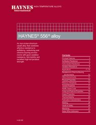
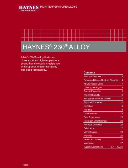
HIGH-TEMPERATURE ALLOYS<br />
HAYNES ® <strong>230</strong> ® ALLOY<br />
A Ni-Cr-W-Mo <strong>alloy</strong> that combines<br />
excellent high-temperature<br />
strength and oxidation resistance<br />
with superior long term stability<br />
and good fabricability.<br />
Contents<br />
Principal Features 3<br />
Creep and Stress-Rupture Strength 4<br />
ASME Vessel Code 7<br />
Low Cycle Fatigue 8<br />
Tensile Properties 9<br />
Thermal Stability 10<br />
Resistance To Grain Growth 11<br />
Physical Properties 12<br />
Oxidation 14<br />
Nitriding 18<br />
Carburization 18<br />
Field Experience 20<br />
Hydrogen Embrittlement 20<br />
Aqueous Corrosion 20<br />
Fabrication 22<br />
Microstructure 23<br />
Welding 24<br />
Health and Safety 26<br />
Machining 27<br />
Typical Applications 2, 17, 19, 21<br />
H-3000H
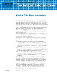
TYPICAL APPLICATIONS<br />
Nitric acid catalyst grids support made from HAYNES ® <strong>230</strong> ® <strong>alloy</strong> plate and bar. Excellent creep strength<br />
at 1700°F (927°C) makes the <strong>alloy</strong> highly suitable for this application.<br />
Textron Lycoming gas turbine engine combustor made of HAYNES <strong>230</strong> <strong>alloy</strong>.<br />
2<br />
©<br />
2007, <strong>Haynes</strong> <strong>International</strong>, <strong>Inc</strong>.
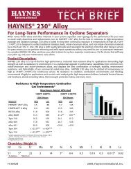
PRINCIPAL FEATURES<br />
Excellent High-Temperature<br />
Strength, Thermal<br />
Stability, and Environment<br />
Resistance<br />
HAYNES ® <strong>230</strong> ® <strong>alloy</strong> is a nickelchromium-tungsten-molybdenum<br />
<strong>alloy</strong> that combines<br />
excellent high-temperature<br />
strength, outstanding resistance<br />
to oxidizing environments<br />
up to 2100°F (1149°C) for<br />
prolonged exposures, premier<br />
resistance to nitriding environments,<br />
and excellent long-term<br />
thermal stability. It is readily<br />
fabricated and formed, and is<br />
castable. Other attractive<br />
features include lower thermal<br />
expansion characteristics than<br />
most high-temperature <strong>alloy</strong>s,<br />
and a pronounced resistance to<br />
grain coarsening with prolonged<br />
exposure to hightemperatures.<br />
Easily Fabricated<br />
HAYNES <strong>230</strong> <strong>alloy</strong> has excellent<br />
forming and welding characteristics.<br />
It may be forged or<br />
otherwise hot-worked, providing<br />
it is held at 2150°F<br />
(1177°C) for a time sufficient to<br />
bring the entire piece to temperature.<br />
As a consequence of<br />
its good ductility, <strong>230</strong> <strong>alloy</strong> is<br />
also readily formed by coldworking.<br />
All hot- or coldworked<br />
parts should be<br />
annealed and rapidly cooled in<br />
order to restore the best<br />
balance of properties.<br />
The <strong>alloy</strong> can be welded by a<br />
variety of techniques, including<br />
gas tungsten arc (GTAW), gas<br />
metal arc (GMAW), and resistance<br />
welding.<br />
Heat-Treatment<br />
Wrought <strong>230</strong> <strong>alloy</strong> is furnished<br />
in the solution heat-treated<br />
condition, unless otherwise<br />
specified. The <strong>alloy</strong> is solution<br />
heat-treated in the range of<br />
2150 to 2275°F (1177 to<br />
1246°C) and rapidly cooled or<br />
water-quenched for optimum<br />
properties.<br />
Annealing at temperatures<br />
lower than the solution heattreating<br />
temperatures will<br />
produce some carbide precipitation<br />
in <strong>230</strong> <strong>alloy</strong>, which may<br />
marginally affect the <strong>alloy</strong>’s<br />
strength and ductility.<br />
Castings<br />
HAYNES <strong>230</strong> <strong>alloy</strong> may be cast<br />
using traditional air-melt sand<br />
mold or vacuum-melt investment<br />
casting foundry practices.<br />
Silicon levels at the high end of<br />
the specification range are<br />
recommended for enhanced<br />
fluidity. Castings may be used<br />
in either the as-cast or solution-heat-treated<br />
condition<br />
depending upon property<br />
requirements.<br />
Available in Convenient<br />
Forms<br />
HAYNES <strong>230</strong> <strong>alloy</strong> is produced<br />
in the form of plate, sheet,<br />
strip, foil, billet, bar, wire<br />
welding products, pipe, tubing,<br />
and remelt bar.<br />
Applications<br />
HAYNES <strong>230</strong> <strong>alloy</strong> combines<br />
properties which make it ideally<br />
suited for a wide variety of<br />
component applications in the<br />
aerospace and power industries.<br />
It is used for combustion<br />
cans, transition ducts,<br />
flameholders, thermocouple<br />
sheaths, and other important<br />
gas turbine components. In the<br />
chemical process industry,<br />
<strong>230</strong> <strong>alloy</strong> is used for catalyst<br />
grid supports in ammonia<br />
burners, high-strength thermocouple<br />
protection tubes, hightemperature<br />
heat exchangers,<br />
ducts, high-temperature<br />
bellows, and various other key<br />
process internals.<br />
In the industrial heating industry,<br />
applications for <strong>230</strong> <strong>alloy</strong><br />
include furnace retorts, chains<br />
and fixtures, burner flame<br />
shrouds, recuperator internals,<br />
dampers, nitriding furnace<br />
internals, heat-treating baskets,<br />
grates, trays, sparger tubes,<br />
thermocouple protection tubes,<br />
cyclone internals, and many<br />
more.<br />
Applicable Specifications<br />
HAYNES <strong>230</strong> <strong>alloy</strong> is covered<br />
by ASME Section VII, Division I.<br />
Plate, sheet, strip, bar, forging,<br />
tubing, pipe, and fittings are<br />
covered by ASME specifications<br />
SB 435, SB 572, SB 564,<br />
SB 619, SB 622, SB 626, and<br />
SB 366 and ASTM specifications<br />
B 435, B 572, B 564, B<br />
619, B 622, B 626, and B 366.<br />
DIN specifications are 17744<br />
No. 2.4733 (all forms) and<br />
NiCr22W14Mo (all forms). The<br />
UNS number for the <strong>alloy</strong> is<br />
N06<strong>230</strong>. Sheet, strip and plate<br />
are also covered by AMS<br />
specification 5878, while bar<br />
and forging are covered by AMS<br />
specification 5891.<br />
ASME Vessel Code<br />
HAYNES <strong>230</strong> <strong>alloy</strong> is covered<br />
by ASME Vessel Code case No.<br />
2063 for Section I and Section<br />
Vlll Division 1 construction to<br />
1650°F (899°C).<br />
Nominal Chemical Composition, Weight Percent<br />
Ni Cr W Mo Fe Co Mn Si Al C La B<br />
57 a 22 14 2 3* 5* 0.5 0.4 0.3 0.10 0.02 0.015*<br />
*Maximum<br />
a<br />
As balance<br />
3
CREEP AND STRESS-RUPTURE STRENGTH<br />
HAYNES ® <strong>230</strong> ® <strong>alloy</strong> is a solidsolution-strengthened<br />
material<br />
which combines excellent hightemperature<br />
strength with good<br />
fabricability at room temperature.<br />
It is particularly effective<br />
for very long-term applications<br />
at temperatures of 1200°F<br />
(649°C) or more, and is capable<br />
of outlasting stainless<br />
steels and nickel <strong>alloy</strong>s by as<br />
much as 100 to 1 depending<br />
upon the temperature. Alternatively,<br />
the higher strength of<br />
<strong>230</strong> <strong>alloy</strong> allows for the use of<br />
design section thicknesses as<br />
much as 75 percent thinner<br />
than lesser <strong>alloy</strong>s with no loss<br />
in load-bearing capability.<br />
Stress-Rupture Lives for Various Alloys at Fixed Test Conditions (Bar and Plate)*<br />
Hours to Rupture<br />
1400°F/15.0 Ksi 1600°F/4.5 Ksi 1800°F/2.0 Ksi<br />
Alloy (760°C/103 MPa) (871°C/31 MPa) (982°C/14 MPa)<br />
<strong>230</strong> ® <strong>alloy</strong> 8,200 65,000 5,000<br />
625 <strong>alloy</strong> 19,000 14,000 2,400<br />
X <strong>alloy</strong> 900 5,000 2,100<br />
Alloy 800H 130 1,200 920<br />
INCONEL ® <strong>alloy</strong> 601 50 1,200 1,000<br />
253 MA ® <strong>alloy</strong> 140 900 720<br />
Alloy 600 15 280 580<br />
Type 316 Stainless Steel 100 240 130<br />
RA330 ® <strong>alloy</strong> 30 <strong>230</strong> 130<br />
Type 304 Stainless Steel 10 100 72<br />
*Based upon Larson-Miller extrapolation<br />
Comparison of Stress to Produce 1% Creep in 1000 Hours (Sheet)<br />
4
Sheet - 2250°F (1232°C) Solution Anneal<br />
Approximate Initial Stress, Ksi (MPa)<br />
Test Temperature Creep, to Produce Specified Creep in:<br />
°F (°C) Percent 10 Hours 100 Hours 1,000 Hours 10,000 Hours*<br />
1200 (649) 0.5 48.0 (330) 32.0 (220) 22.0 (150) ----<br />
1.0 51.0 (350) 36.0 (250) 25.0 (170) ----<br />
Rupture 67.0 (460) 48.0 (330) 36.0 (250) 27.0 (185)<br />
1300 (704) 0.5 31.0 (215) 21.3 (145) 14.5 (100) ----<br />
1.0 34.0 (235) 24.0 (165) 16.5 (115) ----<br />
Rupture 47.0 (325) 34.0 (235) 25.0 (170) 18.5 (130)<br />
1400 (760) 0.5 17.2 (120) 13.7 (95) 10.8 (75) ----<br />
1.0 20.0 (140) 14.8 (100) 11.7 (81) ----<br />
Rupture 32.0 (220) 24.5 (170) 18.2 (125) 13.2 (91)<br />
1500 (816) 0.5 13.1 (90) 10.3 (71) 7.8 (54) ----<br />
1.0 14.1 (97) 11.2 (77) 8.6 (59) ----<br />
Rupture 23.3 (160) 17.5 (120) 12.5 (86) 8.4 (58)<br />
1600 (871) 0.5 l0.0 (69) 7.6 (52) 5.5 (38) ----<br />
1.0 11.0 (76) 8.4 (58) 5.8 (40) ----<br />
Rupture 17.0 (115) 12.1 (83) 8.2 (57) 5.6 (39)<br />
1700 (927) 0.5 7.5 (52) 5.4 (37) 3.4 (23) ----<br />
1.0 8.3 (57) 5.7 (39) 3.6 (25) ----<br />
Rupture 12.0 (83) 8.0 (55) 4.9 (34) 3.2 (22)<br />
1800 (982) 0.5 5.4 (37) 3.4 (23) 1.7 (12) ----<br />
1.0 5.7 (39) 3.6 (25) 1.9 (13) ----<br />
Rupture 8.0 (55) 4.9 (34) 2.6 (18) 1.1 (7.6)<br />
1900 (1038) 0.5 ---- ---- ---- ----<br />
*Significant Extrapolation of Data<br />
1.0 ---- ---- ---- ----<br />
Rupture 7.5 (52) 3.5 (24) 1.6 (11) ----<br />
Plate and Bar - 2250°F (1232°C) Solution Anneal<br />
Approximate Initial Stress, Ksi (MPa)<br />
Test Temperature Creep, to Produce Specified Creep in:<br />
°F (°C) Percent 10 Hours 100 Hours 1,000 Hours 10,000 Hours*<br />
1200 (649) 0.5 59.0 (405) 34.0 (235) 23.0 (160) ----<br />
1.0 60.0 (415) 39.0 (270) 26.4 (180) 17.5 (120)<br />
Rupture ---- 56.0 (385) 42.5 (295) 29.0 (200)<br />
1300 (704) 0.5 30.0 (205) 20.5 (140) 15.0 (105) ----<br />
1.0 35.0 (240) 23.5 (160) 18.0 (125) 12.3 (85)<br />
Rupture 52.0 (360) 39.0 (270) 29.0 (200) 21.0 (145)<br />
1400 (760) 0.5 19.0 (130) 14.0 (97) 11.0 (76) ----<br />
1.0 21.5 (150) 15.9 (110) 11.5 (79) 8.0 (55)<br />
Rupture 37.0 (255) 27.0 (185) 20.0 (140) 14.2 (98)<br />
5
Plate and Bar - 2250°F (1232°C) Solution Anneal (con't)<br />
Approximate Initial Stress, Ksi (MPa)<br />
Test Temperature Creep, to Produce Specified Creep in:<br />
°F (°C) Percent 10 Hours 100 Hours 1,000 Hours 10,000 Hours<br />
1500 (816) 0.5 13.4 (92) 10.6 (73) 8.2 (57) ----<br />
1.0 15.0 (105) 12.0 (83) 9.2 (63) 6.5 (45)<br />
Rupture 26.0 (180) 19.0 (130) 14.0 (97) 9.8 (68)<br />
1600 (871) 0.5 10.3 (71) 8.0 (55) 5.6 (39) ----<br />
1.0 11.7 (81) 9.0 (62) 6 0 (41) 4.4 (30)<br />
Rupture 18.8 (130) 13.7 (95) 9.5 (66) 6.2 (43)<br />
1700 (927) 0.5 7.8 (54) 5.5 (38) 3.4 (23) ----<br />
1.0 8.8 (61) 6.3 (43) 4.0 (28) 2.6 (18)<br />
Rupture 13.4 (92) 9.4 (65) 6.0 (41) 3.5 (24)<br />
1800 (982) 0.5 5.5 (38) 3.4 (23) 1.6 (11) ----<br />
1.0 6.3 (43) 3.8 (26) 2.0 (14) 1.1 (7.6)<br />
Rupture 9.4 (65) 6.0 (41) 3.0 (21) 1.6 (11)<br />
1900(1038)* 0.5 ---- ---- ---- ----<br />
1.0 4.4 (30) 2.0 (14) 0.9 (6.2) ----<br />
Rupture 7.0 (48) 3.5 (24) 1.8 (12) ----<br />
2000(1093)* 0.5 ---- ---- ---- ----<br />
1.0 2.3 (16) 0.8 (5.5) ---- ----<br />
Rupture 4.2 (29) 2.1 (14) 1.0 (6.9) ----<br />
2100(1149)* 0.5 ---- ---- ---- ----<br />
*Based upon limited data<br />
1.0 1.1 (7.6) 0.4 (2.8) ---- ----<br />
Rupture 2.3 (16) 1.2 (8.3) 0.6 (4.1 ) ----<br />
Vacuum Investment Casting (As Cast)<br />
Approximate Initial Stress, Ksi (MPa)<br />
Test Temperature<br />
to Produce Rupture in:<br />
°F (°C) 10 Hours 100 Hours 1,000 Hours 10,000 Hours*<br />
1400 (760) 32.0 (220) 23.8 (165) 18.3 (125) 13.9 (96)<br />
1500 (816) 23.0 (160) 17.4 (120) 13.0 (90) 9.8 (68)<br />
1600 (871) 17.0 (115) 12.5 (86) 9.3 (64) 6.7 (46)<br />
1700 (927) 12.5 (86) 9.0 (62) 6.4 (44) 4.5 (31)<br />
1800 (982) 9.0 (62) 6.4 (44) 4.4 (30) 2.9 (20)<br />
1900 (1038) 6.5 (45) 4.5 (31) 2.9 (20) 1.7 (12)<br />
2000 (1093) 4.7 (32) 3.0 (21) 1.8 (12) ----<br />
2100 (1149) 3.2 (22) 1.9 (13) 0.9 (6.2) ----<br />
*Significant Extrapolation of Data<br />
6
ASME VESSEL CODE ALLOWABLE STRESSES<br />
HAYNES ® <strong>230</strong> ® <strong>alloy</strong> is approved<br />
for ASME Vessel Code<br />
Section I and Section Vlll<br />
Division 1 construction to<br />
1650°F (899°C) in Section II,<br />
Part D for plate, sheet, strip,<br />
bar, and forgings. (See also<br />
Code Case No. 2063 for<br />
Section I, Applications). Allowable<br />
stresses are reprinted<br />
here by permission of the<br />
ASME.<br />
NOTE (1)<br />
Due to the relatively low yield strength of this<br />
material, these higher stress values were<br />
established at temperatures where the short time<br />
tensile properties govern to permit the use of these<br />
<strong>alloy</strong>s where slightly greater deformation is<br />
acceptable. These higher stress values exceed<br />
67%, but do not exceed 90% of the yield strength at<br />
temperature. Use of these stresses may result in<br />
dimensional changes due to permanent strain.<br />
These stress values are not recommended for<br />
flanges of gasketed joints or other applications<br />
where slight amounts of distortion can cause<br />
leakage or malfunction.<br />
ASME Vessel Section II, Part D, Table 1B<br />
Metal<br />
Maximum Allowable Stress Values<br />
Temperatures<br />
Not Exceeding Standard Note (1)<br />
°F °C Ksi MPa Ksi MPa<br />
100 37 30.0 207 30.0 207<br />
200 93 28.2 194 30.0 207<br />
300 149 26.4 182 30.0 207<br />
400 204 24.7 170 30.0 207<br />
500 260 23.1 159 30.0 207<br />
600 315 22.0 152 29.4 203<br />
650 343 21.5 146 29.1 200<br />
700 371 21.2 145 28.7 198<br />
750 398 21.0 145 28.4 196<br />
800 426 20.9 144 28.2 194<br />
850 454 20.9 144 28.2 194<br />
900 482 20.9 144 28.2 194<br />
950 510 20.9 144 28.2 194<br />
1000 537 20.9 144 28.2 194<br />
1050 565 20.9 144 28.2 194<br />
1100 593 20.9 144 23.2 160<br />
1150 621 19.0 131 19.0 131<br />
1200 648 15.6 107 15.6 107<br />
1250 676 12.9 89 12.9 89<br />
1300 704 10.6 73 10.6 73<br />
1350 732 8.5 59 8.5 59<br />
1400 760 6.7 46 6.7 46<br />
1450 787 5.3 37 5.3 37<br />
1500 815 4.1 28 4.1 28<br />
1550 843 2.7 19 2.7 19<br />
1600 871 1.8 12 1.8 12<br />
1650 898 1.2 8 1.2 8<br />
Comparative Design Strength Values*<br />
HAYNES <strong>230</strong> <strong>alloy</strong> exhibits significant<br />
design strength advantages over other<br />
ASME vessel code covered materials for<br />
Section Vlll Division 1 construction at<br />
temperatures up to 1650°F (899°C).<br />
*All values taken from ASME Vessel Code<br />
Section VIII Division 1 or appropriate Code Cases.<br />
7
LOW CYCLE FATIGUE PROPERTIES<br />
HAYNES ® <strong>230</strong> ® <strong>alloy</strong> exhibits<br />
excellent low cycle fatigue<br />
properties at elevated temperature.<br />
Results shown below are<br />
for strain-controlled tests run in<br />
the temperature range from 800<br />
to 1800°F (427 to 982°C).<br />
Samples were machined<br />
from plate. Tests were run with<br />
fully reversed strain (R=-1) at a<br />
frequency of 20 cpm (0.33 Hz).<br />
Comparative Low Cycle Fatigue Properties<br />
The graph below compares the<br />
low cycle fatigue lives of a<br />
number of <strong>alloy</strong>s tested at<br />
800°F (427°C) in both the asreceived<br />
and 1400°F(760°C)/<br />
1000 hour pre-exposed condition.<br />
Samples were machined<br />
from plate or bar, after exposure<br />
for exposed samples.<br />
Tests were again run with<br />
fully reversed strain (R=-1) at a<br />
frequency of 20 cpm (0.33 Hz).<br />
TSR=Total Strain Range.<br />
800°F (427°C) LCF Life for Various Alloys<br />
8
TYPICAL TENSILE PROPERTIES<br />
Cold-Rolled and 2250°F (1232°C) Solution Annealed (Sheet)<br />
Ultimate<br />
Test Tensile Yield Strength Elongation in<br />
Temperature Strength at 0.2% Offset 2 in. (50.8 mm)<br />
°F °C Ksi MPa Ksi MPa %<br />
Room Room 121.6 838 61.3 422 47.2<br />
1000 538 101.5 699 44.0 303 53.7<br />
1200 649 97.2 668 43.6 300 56.7<br />
1400 760 78.3 539 46.9 323 61.2<br />
1600 871 44.7 308 33.9 234 75.0<br />
1800 982 25.0 172 18.2 125 50.2<br />
2000 1093 13.1 90 10.0 69 37.0<br />
Hot-Rolled and 2250°F (1232°C) Solution Annealed (Plate)<br />
Ultimate<br />
Test Tensile Yield Strength Elongation in<br />
Temperature Strength at 0.2% Offset 2 in. (50.8 mm)<br />
°F °C Ksi MPa Ksi MPa %<br />
Room Room 121.8 840 54.4 375 47.7<br />
1000 538 100.1 690 36.4 251 54.6<br />
1200 649 96.0 662 37.0 255 54.5<br />
1400 760 76.9 530 36.7 253 69.5<br />
1600 871 45.6 315 35.1 242 99.5<br />
1800 982 24.7 171 17.0 118 96.3<br />
2000 1093 13.2 91 9.1 63 92.1<br />
Vacuum Investment Castings (As Cast)<br />
Ultimate<br />
Test Tensile Yield Strength Elongation in Reduction<br />
Temperature Strength at 0.2% Offset 5D in Area<br />
°F °C Ksi MPa Ksi MPa % %<br />
Room Room 89.0 615 46.8 325 37.8 37.7<br />
1000 538 65.6 450 33.1 <strong>230</strong> 38.2 35.9<br />
1200 649 69.8 480 32.4 225 44.2 34.9<br />
1400 760 55.8 385 32.9 225 32.3 36.0<br />
1600 871 41.0 285 26.6 185 19.0 29.8<br />
1800 982 29.4 205 24.8 170 25.5 39.9<br />
2000 1093 12.9 89 12.6 87 41.0 46.6<br />
9
Comparison of Yield Strengths (Plate)<br />
THERMAL STABILITY<br />
HAYNES ® <strong>230</strong> ® <strong>alloy</strong> exhibits<br />
excellent retained ductility after<br />
long-term thermal exposure at<br />
intermediate temperatures. It<br />
does not exhibit sigma phase,<br />
mu phase, or other deleterious<br />
phase formation even after<br />
16,000 hours of exposure at<br />
temperatures from 1200 to<br />
1600°F (649 to 871°C). Principal<br />
phases precipitated from<br />
solid solution are all carbides.<br />
This contrasts markedly with<br />
many other solid-solutionstrengthened<br />
super<strong>alloy</strong>s such<br />
as HAYNES 188 <strong>alloy</strong>, HAYNES<br />
625 <strong>alloy</strong>, and HASTELLOY ® X<br />
<strong>alloy</strong>. These <strong>alloy</strong>s all precipitate<br />
deleterious phases, which<br />
impair both tensile ductility and<br />
impact strength.<br />
10
Room-Temperature Properties After Thermal Exposure (Plate)<br />
Ultimate<br />
Exposure Tensile Yield Strength Elongation in Impact<br />
Temperature Strength at 0.2% Offset 2 in. (50.8mm) Strength<br />
°F (°C) Hours Ksi MPa Ksi MPa % ft.-lb. Joules<br />
1200 0 123 850 59 405 51 54 73<br />
(649°C) 1000 130 895 64 440 43 34 46<br />
4000 130 895 59 405 41 29 39<br />
8000 130 895 61 420 38 30 41<br />
16000 133 915 65 450 37 28 38<br />
1400 0 123 850 59 405 51 54 73<br />
(760°C) 1000 128 885 59 405 33 18 24<br />
4000 129 890 55 380 38 22 30<br />
8000 131 905 57 395 35 21 28<br />
16000 132 910 61 420 33 19 26<br />
1600 0 123 850 59 405 51 54 73<br />
(871°C) 1000 126 870 54 370 37 18 24<br />
4000 127 875 51 350 43 26 35<br />
8000 127 875 51 350 36 21 28<br />
16000 129 890 57 395 34 19 26<br />
Comparative Room-Temperature Impact Strength<br />
Solution-Annealed<br />
Charpy V-Notch Impact<br />
Charpy V-Notch Impact after 8000 Hours at Temperatures, ft.-lb. (Joules)<br />
Alloy ft.-lb. (Joules) 1200° F (649°C) 1400°F (760°C) 1600°F (871°C)<br />
<strong>230</strong> ® 54 (73) 30 (41) 21 (28) 21 (28)<br />
625 81 (110) 5 (7) 5 (7) 15 (20)<br />
X 54 (73) 15 (20) 8 (11) 15 (20)<br />
188 143 (194) 23 (31) 3 (4) 9 (12)<br />
RESISTANCE TO GRAIN GROWTH<br />
HAYNES ® <strong>230</strong> ® <strong>alloy</strong> exhibits<br />
excellent resistance to grain<br />
growth at high temperatures.<br />
As a consequence of its very<br />
stable primary carbides, <strong>230</strong><br />
<strong>alloy</strong> can be exposed at temperatures<br />
as high as 2200°F<br />
(1204°C) for up to 24 hours<br />
without exhibiting significant<br />
grain growth. Materials such<br />
as HAYNES 188 <strong>alloy</strong> or<br />
HASTELLOY ® X <strong>alloy</strong> exhibit<br />
greater grain growth under<br />
such conditions, as would most<br />
iron-, nickel-, or cobalt-bae<br />
<strong>alloy</strong>s and stainless steels.<br />
Grain Size for Alloys Exposed at Temperature for Various Times*<br />
(ASTM Grain Size No.)<br />
Exposure <strong>230</strong> <strong>alloy</strong> HAYNES 188 <strong>alloy</strong> HASTELLOY X <strong>alloy</strong><br />
Time 2150°F 2200°F 2150°F 2200°F 2150°F 2200°F<br />
(Hours) (1177°C) (1204°C) (1177°C) 1204°C) (1177°C) (1204°C)<br />
0 4-4 1/2 4-4 1/2 4-5 4-5 3 1/2 3 1/2<br />
1 4-5 4-4 1/2 2-5 2-4 3 1/2 0-1<br />
4 4-4 1/2 4-4 1/2 3 1/2 3 3 1/2 0-1<br />
24 4 4-4 1/2 0-2 1-3 00-4 0-1 1/2<br />
*Plate Product<br />
11
TYPICAL PHYSICAL PROPERTIES<br />
Temperature, °F British Units Temperature, °C Metric Units<br />
Density Room 0.324 lb/in 3 Room 8.97 g/cm 3<br />
Melting Range 2375-2500 1301-1371<br />
Electrical Resistivity Room 49.2 microhm-in. Room 125.0 microhm-cm<br />
200 49.5 microhm-in. 100 125.8 microhm-cm<br />
400 49.8 microhm-in. 200 126.5 microhm-cm<br />
600 50.2 microhm-in. 300 127.3 microhm-cm<br />
800 50.7 microhm-in. 400 128.4 microhm-cm<br />
1000 51.5 microhm-in. 500 130.2 microhm-cm<br />
1200 51.6 microhm-in. 600 131.2 microhm-cm<br />
1400 51.1 microhm-in. 700 130.7 microhm-cm<br />
1600 50.3 microhm-in. 800 129.1 microhm-cm<br />
1800 49.3 microhm-in. 900 127.1 microhm-cm<br />
1000 125.0 microhm-cm<br />
Thermal Diffusivity Room 3.8 x 10 -3 in. 2 /sec. Room 24.2 x 10 -3 cm 2 /sec.<br />
200 4.1 x 10 -3 in. 2 /sec. 100 26.8 x 10 -3 cm 2 /sec.<br />
400 4.7 x 10 -3 in. 2 /sec. 200 29.9 x 10 -3 cm 2 /sec.<br />
600 5.2 x 10 -3 in. 2 /sec. 300 32.9 x 10 -3 cm 2 /sec.<br />
800 5.6 x 10 -3 in. 2 /sec. 400 35.7 x 10 -3 cm 2 /sec.<br />
1000 6.1 x 10 -3 in. 2 /sec. 500 38.5 x 10 -3 cm 2 /sec.<br />
1200 6.5 x 10 -3 in. 2 /sec. 600 41.9 x 10 -3 cm 2 /sec.<br />
1400 6.7 x 10 -3 in. 2 /sec. 700 43.0 x 10 -3 cm 2 /sec.<br />
1600 6.7 x 10 -3 in. 2 /sec. 800 43.2 x 10 -3 cm 2 /sec.<br />
1800 7.3 x 10 -3 in. 2 /sec. 900 44.4 x 10 -3 cm 2 /sec.<br />
1000 48.2 x 10 -3 cm 2 /sec.<br />
Thermal Conductivity Room 62 Btu-in./ft. 2 hr.-°F Room 8.9 W/m-K<br />
200 71 Btu-in./ft. 2 hr.-°F 100 10.4 W/m-K<br />
400 87 Btu-in./ft. 2 hr.-°F 200 12.4 W/m-K<br />
600 102 Btu-in./ft. 2 hr.-°F 300 14.4 W/m-K<br />
800 118 Btu-in./ft. 2 hr.-°F 400 16.4 W/m-K<br />
1000 133 Btu-in./ft. 2 hr.-°F 500 18.4 W/m-K<br />
1200 148 Btu-in./ft. 2 hr.-°F 600 20.4 W/m-K<br />
1400 164 Btu-in./ft. 2 hr.-°F 700 22.4 W/m-K<br />
1600 179 Btu-in./ft. 2 hr.-°F 800 24.4 W/m-K<br />
1800 195 Btu-in./ft. 2 hr.-°F 900 26.4 W/m-K<br />
1000 28.4 W/m-K<br />
12
Typical Physical Properties (continued)<br />
Temperature,<br />
Temperature,<br />
°F British Units °C Metric Units<br />
Specific Heat Room 0.095 Btu/lb.-°F Room 397 J/Kg-K<br />
200 0.099 Btu/lb.-°F 100 419 J/Kg-K<br />
400 0.104 Btu/lb.-°F 200 435 J/Kg-K<br />
600 0.108 Btu/lb.-°F 300 448 J/Kg-K<br />
800 0.112 Btu/lb.-°F 400 465 J/Kg-K<br />
1000 0.112 Btu/lb.-°F 500 473 J/Kg-K<br />
1200 0.134 Btu/lb.-°F 600 486 J/Kg-K<br />
1400 0.140 Btu/lb.-°F 700 574 J/Kg-K<br />
1600 0.145 Btu/lb.-°F 800 595 J/Kg-K<br />
1800 0.147 Btu/lb.-°F 900 609 J/Kg-K<br />
1000 617 J/Kg-K<br />
Mean Coefficient of 70-200 6.5 microinches/in.-°F 25-100 11.8 10 -6 m/m-°C<br />
Thermal Expansion 70-400 6.9 microinches/in.-°F 25-200 12.4 10 -6 m/m-°C<br />
70-600 7.2 microinches/in.-°F 25-300 12.8 10 -6 m/m-°C<br />
70-800 7.4 microinches/in.-°F 25-400 13.2 10 -6 m/m-°C<br />
70-1000 7.6 microinches/in.-°F 25-500 13.6 10 -6 m/m-°C<br />
70-1200 8.0 microinches/in.-°F 25-600 14.1 10 -6 m/m-°C<br />
70-1400 8.3 microinches/in.-°F 25-700 14.7 10 -6 m/m-°C<br />
70-1600 8.6 microinches/in.-°F 25-800 15.2 10 -6 m/m-°C<br />
70-1800 8.9 microinches/in.-°F 25-900 15.7 10 -6 m/m-°C<br />
25-1000 16.1 10 -6 m/m-°C<br />
Dynamic Modulus of Elasticity<br />
Dynamic<br />
Dynamic<br />
Modulus of<br />
Modulus of<br />
Elasticity,<br />
Elasticity,<br />
Temperature, °F 10 6 psi Temperature, °C GPa<br />
Room 30.6 Room 211<br />
200 30.1 100 207<br />
400 29.3 200 202<br />
600 28.3 300 196<br />
800 27.3 400 190<br />
1000 26.4 500 184<br />
1200 25.3 600 177<br />
1400 24.1 700 171<br />
1600 23.1 800 164<br />
1800 21.9 900 157<br />
1000 150<br />
13
Thermal Expansion Characteristics<br />
HAYNES ® <strong>230</strong> <strong>alloy</strong> has<br />
relatively low thermal expansion<br />
characteristics compared to<br />
most high-strength super<strong>alloy</strong>s,<br />
iron-nickel-chromium <strong>alloy</strong>s,<br />
and austenitic stainless steels.<br />
This means lower thermal<br />
stresses in service for complex<br />
component fabrications, as well<br />
as tighter control over critical<br />
part dimensions and clearances.<br />
Expansion Coefficient, µin/in-°F<br />
11<br />
10<br />
9<br />
8<br />
Room Temperature To T (°C)<br />
200 300 400 500 600 700 800 900<br />
Type 304<br />
Alloy 600<br />
<strong>230</strong> <strong>alloy</strong><br />
Alloy 800H<br />
Alloy X<br />
1000<br />
Alloy 188<br />
20<br />
18<br />
16<br />
14<br />
Expansion Coefficient, µm/m-°C<br />
7<br />
12<br />
400 600 800 1000 1200 1400 1600 1800<br />
Room Temperature To T (°F)<br />
OXIDATION RESISTANCE<br />
HAYNES <strong>230</strong> <strong>alloy</strong> exhibits<br />
excellent resistance to both air<br />
and combustion gas oxidizing<br />
environments, and can be used<br />
for long-term continuous<br />
exposure at temperatures up to<br />
2100 deg. F (1149 deg. C). For<br />
exposures of short duration,<br />
<strong>230</strong> <strong>alloy</strong> can be used at higher<br />
temperatures.<br />
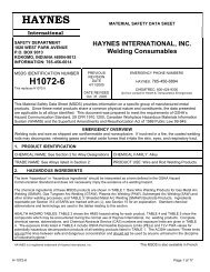
Schematic Representation of Metallographic Technique used for Evaluating Oxidation Tests<br />
1. Metal Loss = (A-B)/2<br />
2. Average Internal Penetration = C<br />
3. Maximum Internal Penetration = D<br />
4. Average Metal Affected = ((A-B)/2) + C<br />
5. Maximum Metal Affected = ((A-B)/2) + D<br />
HAYNES <strong>230</strong> <strong>alloy</strong><br />
14
Comparative Burner Rig Oxidation Resistance 1000 Hour Exposure at 1800°F (982°C)<br />
Metal Average Maximum<br />
Loss Metal Affected Metal Affected<br />
Alloy Mils µm Mils µm Mils µm<br />
<strong>230</strong> ® <strong>alloy</strong> 0.8 20 2.8 71 3.5 89<br />
HAYNES ® 188 <strong>alloy</strong> 1.1 28 3.5 89 4.2 107<br />
HASTELLOY ® X <strong>alloy</strong> 2.7 69 5.6 142 6.4 163<br />
625 Alloy 4.9 124 7.1 180 7.6 193<br />
RA330 <strong>alloy</strong> 7.8 198 10.6 269 11.8 300<br />
Type 310 Stainless Steel 13.7 348 16.2 406 16.5 419<br />
Alloy 600 12.3 312 14.4 366 17.8 452<br />
INCONEL <strong>alloy</strong> 601 3.0 76 18.8 478 20.0 508<br />
Oxidation Test Parameters<br />
Burner rig oxidation tests were<br />
conducted by exposing samples<br />
3/8 inch x 2.5 inches x thickness<br />
(9 mm x 64 mm x thickness),<br />
in a rotating holder, to<br />
the products of combustion of<br />
No. 2 fuel oil burned at a ratio of<br />
air to fuel of about 50:1. (Gas<br />
velocity was about 0.3 mach.)<br />
Samples were automatically<br />
removed from the gas stream<br />
every 30 minutes and fancooled<br />
to near ambient temperature<br />
and then reinserted<br />
into the flame tunnel.<br />
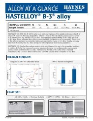
Comparative Burner Rig Oxidation Resistance at 2000°F (1093°C) for 500 Hours<br />
(Width of Micros Indicates Original Sample Thickness)<br />
<strong>230</strong> <strong>alloy</strong><br />
Average Metal Affected<br />
= 5.2 Mils (132 µm)/Side<br />
Alloy 600<br />
Average Metal Affected<br />
= 19.5 Mils (495 µm)/Side<br />
Type 310 Stainless Steel<br />
Average Metal Affected<br />
= 23.7 Mils (602 µm)/Side<br />
HASTELLOY X <strong>alloy</strong><br />
Average Metal Affected<br />
= 12.9 Mils (328 µm)/Side<br />
RA330 Alloy<br />
Average Metal Affected<br />
= 12.9 Mils (328 µm)/Side<br />
INCONEL <strong>alloy</strong> 601<br />
Average Metal Affected<br />
= > 24.0 Mils (610 µm)/Side<br />
15
Comparative Oxidation Resistance in Flowing Air*<br />
Average Metal Affected in 1008 Hours**<br />
1800°F (982°C) 2000°F (1093°C) 2100°F (1149°C) 2200°F(1204°C)<br />
Alloy Mils µm Mils µm Mils µm Mils µm<br />
HAYNES ® <strong>230</strong> ® <strong>alloy</strong> 0.7 18 1.3 33 3.4 86 7.9 201<br />
HAYNES 188 <strong>alloy</strong> 0.6 15 1.3 33 8.0 203 >21.7 >551<br />
INCONEL <strong>alloy</strong> 601 1.3 33 2.6 66 5.3 135 7.5*** 191***<br />
HASTELLOY ® X <strong>alloy</strong> 0.9 23 2.7 69 5.8 147 >35.4 >889<br />
Alloy 625 0.7 18 4.8 122 18.2 462 >47.6 >1209<br />
Alloy 800H 1.8 46 7.4 188 8.9 226 13.6 289<br />
Type 446 Stainless Steel 2.3 58 14.5 368 >21.7 >551 >23.3 >592<br />
Type 316 Stainless Steel 14.3 363 >68.4 >1737 >105.0 >2667 >140.4 >3566<br />
*Flowing air at a velocity of 7.0 feet/minute (213.4 cm/minute) past the samples. Samples cycled to room temperature once-a-week.<br />
**Metal Loss + Average Internal Penetration<br />
***601 Sample exhibited very large internal voids.<br />
Comparative Oxidation in Flowing Air 2100°F (1149°C) For 1008 Hours<br />
Microstructures shown are for<br />
coupons exposed for 1008 hours<br />
at 2100°F (1149°C) in air flowing<br />
7.0 feet/minute (2.1 m/minute) past<br />
the samples. Samples were<br />
descaled by cathodically charging<br />
the coupons while they were<br />
immersed in a molten salt<br />
solution. The black area shown at<br />
the top of each picture represents<br />
actual metal loss due to oxidation.<br />
The data clearly show HAYNES <strong>230</strong><br />
<strong>alloy</strong> to be superior to both<br />
INCONEL <strong>alloy</strong> 601 and <strong>alloy</strong><br />
800H, as well as the other heatresistant<br />
materials listed in the table<br />
above.<br />
<strong>230</strong> <strong>alloy</strong><br />
Average Metal Affected<br />
= 3.4 mils (86 µm)<br />
INCONEL <strong>alloy</strong> 601<br />
Average Metal Affected<br />
= 5.3 mils (135 µm)<br />
Alloy 800H<br />
Average Metal Affected<br />
= 8.9 mils (226 µm)<br />
16
TYPICAL APPLICATIONS<br />
Prototype <strong>230</strong> ® combustor for Dresser-Rand DR-990 land-based turbine.<br />
Resistance-heated <strong>230</strong> superheater<br />
tubes at the Penn State Applied<br />
Research Laboratory. Used to<br />
produce about 1625°F (885°C) highpressure<br />
steam.<br />
Prototype <strong>230</strong> high-temperature expansion bellows made of<br />
0.020-inch (0.5mm) thick sheet in a catalytic cracker<br />
configuration.<br />
17
NITRIDING RESISTANCE<br />
HAYNES ® <strong>230</strong> ® <strong>alloy</strong> is one of<br />
the most nitriding resistant<br />
materials commercially available.<br />
Tests were performed in<br />
flowing ammonia at 1200°F<br />
(649°C) and 1800°F (982°C)<br />
for 168 hours. Nitrogen<br />
absorption was determined<br />
by chemical analysis of<br />
samples before and after<br />
exposure and knowledge of the<br />
exposed specimen area.<br />
Nitrogen Absorption (mg/cm 2 )<br />
Alloy 1200°F (649°C) 1800°F (982°C)<br />
HAYNES ® <strong>230</strong> ® <strong>alloy</strong> 0.7 1.4<br />
Alloy 600 0.8 0.9<br />
Alloy 625 0.8 2.5<br />
HASTELLOY ® X <strong>alloy</strong> 1.7 3.2<br />
RA330 Alloy 3.9 -<br />
Alloy 800H 4.3 4.0<br />
Type 316 Stainless Steel 6.9 6.0<br />
Type 310 Stainless Steel 7.4 7.7<br />
Type 304 Stainless Steel 9.7 7.3<br />
CARBURIZATION RESISTANCE<br />
HAYNES <strong>230</strong> <strong>alloy</strong> exhibits<br />
good resistance to carburization<br />
when compared with many<br />
other industrial <strong>alloy</strong>s. Test<br />
results were generated for 500<br />
hours exposure in packed<br />
graphite at 1800°F (982°C).<br />
Carbon absorption was<br />
determined by chemical<br />
analysis of samples before and<br />
after exposure and knowledge<br />
of the exposed specimen area.<br />
18
TYPICAL APPLICATIONS<br />
This horizontal electrically fired <strong>230</strong> ® retort replaced an<br />
<strong>alloy</strong> 600 retort which lasted only an average of eight<br />
months in 1400 to 2200°F (760 to 1204°C) service in<br />
hydrogen atmosphere. The <strong>230</strong> retort was still in<br />
excellent condition after 24 months service, as shown.<br />
Wire annealing fixture of <strong>230</strong> <strong>alloy</strong> reduces<br />
thermal mass and cycle times after replacing<br />
massive carbon-steel “stub” used previously.<br />
Fabricated heat-treating basket for vacuum furnace application<br />
to <strong>230</strong>0°F (1260°C). Made from 1/2-inch (12.7 mm)<br />
diameter <strong>230</strong> bar.<br />
This striking shot of a HAYNES <strong>230</strong> heat-treat<br />
fixture was taken at a leading off-road<br />
automotive equipment plant. This conveyor<br />
fixture operates at 1550°F (843°C) with a<br />
subsequent water quench followed by a four<br />
hour cycle at 1050°F (566°C).<br />
19
FIELD EXPERIENCE - WASTE INCINERATION<br />
Coupon exposures performed<br />
in the flue of an industrial waste<br />
incinerator burning wood,<br />
cardboard, and other plant<br />
waste revealed that HAYNES ®<br />
<strong>230</strong> ® <strong>alloy</strong> was very resistant to<br />
the mildly sulfidizing flue gases<br />
produced. Coupons were<br />
exposed in the average 1700°F<br />
(927°C) gases for more than<br />
400 hours over 31 days. Seven<br />
start-up/shut-down cycles were<br />
experienced.<br />
HYDROGEN EMBRITTLEMENT RESISTANCE<br />
Notched tensile tests performed<br />
in hydrogen and air reveal that<br />
<strong>230</strong> <strong>alloy</strong> is resistant to hydrogen<br />
embrittlement. Tests were<br />
performed in MIL-P-27201B<br />
grade hydrogen, with a crosshead<br />
speed of 0.005 in/min (0.13<br />
mm/min). Specimens were<br />
notched with a K T<br />
value of 8.0.<br />
Ratio of Notched<br />
Temperature Hydrogen Pressure Tensile Strength<br />
°F °C Psig MPa Hydrogen/Air<br />
70 21 3000 21 0.92<br />
70 21 5000 34 1.07<br />
1200 649 3000 21 1.00<br />
1600 871 3000 21 1.00<br />
AQUEOUS CORROSION RESISTANCE<br />
Coupons were exposed for four<br />
24-hour periods in various acids<br />
at the stated temperatures, and<br />
general corrosion rates were<br />
calculated from weight change<br />
measurements.<br />
Corrosion Rate (mils per year)<br />
10% HNO 3<br />
10% H 2<br />
SO 4<br />
10%HCl<br />
Boiling 150°F (66°C) 150°F (66°C)<br />
<strong>230</strong> <strong>alloy</strong> 0.3 0.6 112<br />
Alloy 625 0.7 0.4 65<br />
Alloy 600 0.8 41.8 366<br />
Type 316 Stainless Steel 1.0 17.8 3408<br />
HASTELLOY X <strong>alloy</strong> -
TYPICAL APPLICATIONS<br />
HAYNES ® <strong>230</strong> ® damper atop this glass melting<br />
furnace withstands <strong>230</strong>0°F (1260°C) for short times<br />
and 2000°F (1093°C) for sustained periods.<br />
Cast heat-treat basket of <strong>230</strong> <strong>alloy</strong> in use at Alloy<br />
Foundries, Division of the Eastern Company,<br />
Naugatuck, Connecticut.<br />
Substrate holder and box of <strong>230</strong> <strong>alloy</strong> resist<br />
temperatures of 1650°F (899°C) during the<br />
production of semiconductors.<br />
<strong>230</strong> retorts operate at 2100°F (1149°C) with a<br />
hydrogen atmosphere (inside) and combustion<br />
products outside.<br />
21
FABRICATION CHARACTERISTICS<br />
Heat Treatment<br />
HAYNES ® <strong>230</strong> ® <strong>alloy</strong> is normally<br />
final solution heat-treated at 2250°F<br />
(1232°C) for a time commensurate<br />
with section thickness. Solution<br />
heat-treating can be performed at<br />
temperatures as low as about<br />
2125°F (1163°C), but resulting<br />
material properties will be altered<br />
accordingly. Annealing during<br />
fabrication can be performed at<br />
even lower temperatures, but a final,<br />
subsequent solution heat<br />
treatment is needed to produce<br />
optimum properties and structure.<br />
Please refer to following sections<br />
and publication H-3159 for<br />
additional information.<br />
Typical Hardness Properties<br />
45<br />
40<br />
Hardness, R B<br />
100<br />
98<br />
96<br />
94<br />
Sheet Hardness<br />
at Room Sheet Temperature<br />
Hardness<br />
at Room Temperature<br />
35<br />
30<br />
25<br />
20<br />
Hardness, R C<br />
Solution Annealed<br />
Room Temperature Hardness<br />
Pieces<br />
Form R B<br />
Tested<br />
Sheet 92.5 37<br />
Plate 95.2 26<br />
Bar 92.7 24<br />
92<br />
90<br />
0 10 20 30 40 50<br />
% Cold Reduction<br />
Effect of Cold Reduction Upon Room-Temperature Tensile Properties*<br />
Ultimate<br />
Percent Subsequent Tensile Yield Strength Elongation in<br />
Cold Anneal Strength at 0.2% Offset 2 in. (50.8 mm)<br />
Reduction Temperature Ksi MPa Ksi MPa %<br />
0 128.2 885 61.8 425 46.6<br />
10 144.5 995 104.0 715 31.8<br />
20 None 163.9 1130 133.4 920 16.8<br />
30 187.5 1295 160.1 1105 9.7<br />
40 201.5 1390 172.4 1190 7.5<br />
50 214.6 1480 184.6 1275 6.0<br />
22
Effect of Cold Reduction Upon Room-Temperature Tensile Properties*- (cont.)<br />
Ultimate<br />
Percent Subsequent Tensile Yield Strength Elongation in<br />
Cold Anneal Strength at 0.2% Offset 2 in. (50.8 mm)<br />
Reduction Temperature Ksi MPa Ksi MPa %<br />
10 143.5 990 91.9 635 32.9<br />
20 1950°F 141.9 980 80.8 555 35.6<br />
30 (1066°C) 142.1 980 75.9 525 35.7<br />
40 for 5 min. 145.5 1005 81.2 560 32.3<br />
50 147.7 1020 86.1 595 34.6<br />
10 139.0 960 80.8 555 36.5<br />
20 2050°F 135.7 935 65.4 450 39.2<br />
30 (1121°C) 140.0 965 72.0 495 37.6<br />
40 for 5 min. 142.3 980 76.1 525 35.5<br />
50 143.9 990 80.8 555 36.3<br />
10 129.5 895 55.5 385 43.7<br />
20 2150°F 134.3 925 64.4 445 40.1<br />
30 (1177°C) 138.1 950 70.2 485 38.5<br />
40 for 5 min. 139.2 960 73.4 505 38.1<br />
50 137.7 950 71.9 495 39.1<br />
*Based upon rolling reductions taken upon 0.120-inch (3.0 mm) thick sheet. Duplicate tests.<br />
TYPICAL MICROSTRUCTURE<br />
(ASTM 5 grain size) Annealed at 2250°F (1232°C)<br />
Etchant 95ml<br />
HCl plus 5 gm<br />
oxalic acid, 4 volts<br />
23
WELDING<br />
HAYNES ® <strong>230</strong> ® <strong>alloy</strong> is readily<br />
welded by Gas Tungsten Arc<br />
Welding (GTAW), Gas Metal Arc<br />
Welding (GMAW) Shielded<br />
Metal Arc Welding (SMAW), and<br />
resistance welding techniques.<br />
Its welding characteristics are<br />
similar to those for<br />
HASTELLOY ® X <strong>alloy</strong>. Submerged-Arc<br />
welding is not<br />
recommended as this process<br />
is characterized by high heat<br />
input to the base metal and<br />
slow cooling of the weld.<br />
These factors can increase<br />
weld restraint and promote<br />
cracking.<br />
Base Metal Preparation<br />
The welding surface and<br />
adjacent regions should be<br />
thoroughly cleaned with an<br />
appropriate solvent prior to any<br />
welding operation. All greases,<br />
oils, cutting oils, crayon marks,<br />
machining solutions, corrosion<br />
products, paint, scale, dye<br />
penetrant solutions, and other<br />
foreigh matter should be<br />
completely removed. It is<br />
preferable, but not necessary,<br />
that the <strong>alloy</strong> be in the solutionannealed<br />
condition when<br />
welded.<br />
Filler Metal Selection<br />
HAYNES <strong>230</strong>-W filler wire<br />
(AWS A5.14, ERNiCrWMo-1) is<br />
recommended for joining <strong>230</strong><br />
<strong>alloy</strong> by Gas Tungsten Arc or<br />
Gas Metal Arc welding. Coated<br />
electrodes of <strong>230</strong>-W <strong>alloy</strong> are<br />
also available for Shielded<br />
Metal Arc welding in non-ASME<br />
code construction . For dissimilar<br />
metal joining of <strong>230</strong><br />
<strong>alloy</strong> to nickel-, cobalt-, or ironbase<br />
materials, <strong>230</strong>-W filler<br />
wire, HAYNES 556 <strong>alloy</strong>,<br />
HASTELLOY S <strong>alloy</strong> (AMS 5838)<br />
or HASTELLOY W <strong>alloy</strong> (AMS<br />
5786, 5787) welding products<br />
may all be considered, depending<br />
upon the particular case.<br />
Please see HAYNES publication<br />
H-3159 for more information.<br />
Preheating, Interpass<br />
Temperatures, and Post-<br />
Weld Heat Treatment<br />
Preheat is not required.<br />
Preheat is generally specified<br />
as room temperature (typical<br />
shop conditions). Interpass<br />
temperature should be maintained<br />
below 200°F (93°C).<br />
Auxiliary cooling methods may<br />
be used between weld passes,<br />
as needed, providing that such<br />
methods do not introduce<br />
contaminants. Post-weld heat<br />
treatment is not generally<br />
required for <strong>230</strong> <strong>alloy</strong>. For<br />
further information please<br />
consult HAYNES publication<br />
H-3159.<br />
Nominal Welding Parameters<br />
Nominal welding parameters<br />
are provided as a guide for<br />
performing typical operations.<br />
These are based upon welding<br />
conditions used in our laboratories.<br />
Details are given for<br />
GTAW, GMAW and SMAW<br />
welding.<br />
Automatic Gas Tungsten-Arc Welding<br />
Square Butt Joint - No Filler Metal Added<br />
Material Thickness<br />
0.040" (1.0 mm) 0.063" (1.6 mm) 0.125" (3.2 mm)<br />
Current (DCEN), amperes 50 80 120<br />
Voltage, volts 8 8.5 9.5<br />
Travel Speed, in/min. (mm/min) 10 (254) 12 (305) 12 (305)<br />
Electrode Size - EWTH-2, in (mm) 0.063 (1.6) 0.094 (2.4) 0.125 (3.6)<br />
Electrode Shape 45° inc 45° inc 45° inc<br />
Cup Size #8 #8 #8<br />
Shield Gas Flow, CFH (liters per min.) 30 (14.2) 30 (14.2) 30 (14.2)<br />
Gas argon argon argon<br />
Backing Gas Flow, CFH (liters per min.) 10 (4.7) 10 (4.7) 10 (4.7)<br />
Gas argon argon argon<br />
24
Manual Gas Tungsten Arc Welding<br />
V-or U-Groove - All Thicknesses 0.125" (3.6 mm) or greater<br />
Technique - Stringer Bead<br />
Current (DCEN), amperes - 120 root, 140-150 Fill<br />
Voltage, volts - 11 to 14<br />
Filler Metal - <strong>230</strong>-W filler wire,<br />
0.125" (3.6 mm) diameter<br />
Travel Speed, in/min (mm/min) - 4 to 6 (102 to 152)<br />
Electrode Size - EWTH-2, in (mm) - 0.125 (3.6)<br />
Electrode Shape - 30° included<br />
Cup Size - #8 or larger<br />
Shield Gas Flow, CFH (liters per min.) - 30 to 35 (14.2 to 16.5)<br />
Gas - Argon<br />
Backup Gas Flow, CFH (liters per min.) - 10 (4.7)<br />
Gas - Argon<br />
Preheat - None if T > 32°F (0°C)<br />
Interpass Temperature Maximum - 212°F (100°C)<br />
Gas Metal Arc Welding<br />
Short Circuiting Transfer Mode - All Thicknesses 0.090" (2.3 mm) or greater<br />
Technique - Stringer Bead or Slight Weave<br />
Current (DCEP), amperes - 100 to 130<br />
Voltage, volts - 18 to 21<br />
Feed Rate, in/min (m/min) - 170 to 190 (4.3 to 4.8)<br />
Stickout, in (min) - 0.5 to 0.75 (12.7 to 19.1)<br />
Filler Metal - <strong>230</strong>-W filler wire,<br />
0.045" (1.1 mm) diameter<br />
Travel Speed, in/min (mm/min) - 8 to 14 (203 to 356)<br />
Torch Gas Flow, CFPH (LPH) - 50 (1416)<br />
Gas - Ar-25% He<br />
Typical Shielded Metal Arc Welding Parameters (Flat Position)*<br />
Electrode Approximate Welding Current<br />
Diameter Welding Voltage Aim Range<br />
in. (mm) Volts Amps Amps<br />
3/32 (2.4) 22-24 65-70 55-75<br />
1/8 (3.2) 22-24 90-100 80-100<br />
5/32 (4.0) 22-25 130-140 125-150<br />
3/16 (4.8) 24-26 160-170 150-180<br />
*DCEP<br />
25
Typical Tensile Properties For GMAW Deposit Weld Metal<br />
Ultimate<br />
Test Tensile Yield Strength Elongation in<br />
Temperature Strength at 0.2% Offset 2 in. (50.8 mm)<br />
°F °C Ksi MPa Ksi MPa %<br />
Room Room 113.9 785 71.0 490 48.2<br />
1000 538 88.7 610 62.8 435 34.8<br />
1600 871 44.7 310 39.6 275 45.4<br />
Typical face and root bends for<br />
welded <strong>230</strong> ® <strong>alloy</strong> 0.5-inch (13 mm)<br />
plate and matching filler metal.<br />
Bend radius was 1.0-inch (25 mm).<br />
HEALTH AND SAFETY INFORMATION<br />
Those involved with the welding<br />
industry are obligated to provide<br />
safe working conditions and be<br />
aware of the potential hazards<br />
associated with welding fumes,<br />
gases, radiation, electrical<br />
shock, heat, eye injuries, burns,<br />
etc. Various local, municipal,<br />
state, and federal regulations<br />
(OSHA, for example) relative to<br />
the welding and cutting processes<br />
must be considered.<br />
Nickel-, cobalt-, and iron-based<br />
<strong>alloy</strong> products may contain, in<br />
varying concentrations, the<br />
following elemental constituents:<br />
aluminum, cobalt, chromium,<br />
copper, iron, manganese,<br />
molybdenum, nickel, and<br />
tungsten. For specific concentrations<br />
of these and other elements<br />
present, refer to the<br />
Material Safety Data Sheets<br />
(MSDS) H2071 and H1072 for<br />
the product.<br />
The operation and maintenance<br />
of welding and cutting equipment<br />
should conform to the provisions<br />
of American National Standard<br />
ANSI Z49.1, Safety in Welding<br />
and Cutting. Attention is especially<br />
called to Section 4<br />
(Protection of Personnel),<br />
Section 5 (Ventilation), and<br />
Section 7 (Confined Spaces) of<br />
that document. Adequate<br />
ventilation is required during all<br />
welding and cutting operations.<br />
Specific requirements are<br />
included in Section 5 for natural<br />
ventilation versus mechanical<br />
ventilation methods. When<br />
welding in confined spaces,<br />
ventilation shall also be sufficient<br />
to assure adequate oxygen for<br />
life support.<br />
The following precautionary<br />
warning, which is supplied with<br />
all welding products, should be<br />
provided to, and fully understood<br />
by, all employees involved<br />
with welding.<br />
Caution<br />
Welding may produce fumes and<br />
gases hazardous to health. Avoid<br />
breathing these fumes and gases.<br />
26<br />
Use adequate ventilation. See<br />
ANSI/AWS Z49.1, Safety in<br />
Welding and Cutting published by<br />
the American Welding Society.<br />
EXPOSURES: Maintain all exposures<br />
below the limits shown in the<br />
Material Safety Data Sheet, and the<br />
product label. Use industrial<br />
hygiene air monitoring to ensure<br />
compliance with the recommended<br />
exposure limits. ALWAYS USE<br />
EXHAUST VENTILATION .<br />
RESPIRATORY PROTECTION: Be<br />
sure to use a fume respirator or air<br />
supplied respirator when welding in<br />
confined spaces or where local<br />
exhaust or ventilation does not<br />
keep exposure below the PEL and<br />
TLV limits.<br />
WARNING: Protect yourself and<br />
others. Be sure the label is read<br />
and understood by the welder.<br />
FUMES and GASES can be<br />
dangerous to your health. Overexposure<br />
to fumes and gases can<br />
result in LUNG DAMAGE. ARC<br />
RAYS can injure eyes and burn<br />
skin. ELECTRIC SHOCK can kill.
MACHINING<br />
HAYNES ® <strong>230</strong> ® <strong>alloy</strong> is similar<br />
in machining characteristics to<br />
other solid-solution-strengthened<br />
nickel-base <strong>alloy</strong>s. These<br />
<strong>alloy</strong>s as a group are classified<br />
as moderate to difficult to<br />
machine; however, it should be<br />
emphasized that they can be<br />
machined using conventional<br />
methods at satisfactory rates.<br />
As these <strong>alloy</strong>s will work-harden<br />
rapidly, the keys to successful<br />
machining are to use slower<br />
speeds and feeds, and to take<br />
heavier cuts than would be<br />
used for machining stainless<br />
steels. See <strong>Haynes</strong> <strong>International</strong><br />
publication H-3159 for<br />
more detailed information.<br />
Normal Roughing (Turning/Facing)<br />
Use carbide C-2/C-3 grade tool Negative rake square insert, 45° SCEA 1<br />
1/32 in. nose radius. Tool holder: 5° negative<br />
Speed: 90 surface feet/minute<br />
back and side rakes.<br />
Feed: 0.010 in./revolution<br />
Depth of Cut: 0.150 in. Lubricant: Dry 2 , Oil 3 or water-base 4,5<br />
Finishing (Turning/Facing)<br />
Use carbide C-2/C-3 grade tool<br />
Speed: 95-110 surface feet/minute<br />
Feed: 0.005-0.007 in./revolution<br />
Depth of Cut: 0.040 in.<br />
Positive rake square insert, if possible,<br />
45° SCEA, 1/32 in. nose radius. Tool holder:<br />
5° positive back and side rakes.<br />
Lubricant: Dry or water-base<br />
Drilling<br />
Use high speed steel M-33/M-40 series 6 /<br />
or T-15 grades*<br />
Short, heavy-web drills with 135° crank shaft<br />
point. Thinning of web at point may reduce thrust.<br />
Speed: 10-15 surface feet/minute (200<br />
RPM maximum for 1/4 in. diameter or smaller)<br />
Feed (per revolution):<br />
0.001 in. rev. 1/8 in. dia. 0.002 in. rev. 1/4 in. dia.<br />
Lubricant: Oil or water-base. Use coolant 0.003 in. rev. 1/2 in. dia. 0.005 in. rev. 3/4 in. dia.<br />
feed drills if possible 0.007 in. rev. 1 in. dia.<br />
* Carbide drills not recommended, but may be used in some set-ups. See <strong>Haynes</strong> <strong>International</strong> publication H-3159 for details.<br />
Notes:<br />
1<br />
SCEA-Side cutting edge angle, or lead angle of the tool.<br />
2<br />
At any point where dry cutting is recommended, an air jet directed on the tool may provide<br />
substantial tool life increases. A water-base coolant mist may also be effective.<br />
3<br />
Oil coolant should be a premium quality, sulfochlorinated oil with extreme pressure additives. A<br />
viscosity at 100°F from 50 to 125 SSU is standard.<br />
4<br />
Water-base coolant should be a 15:1 mix of water with either a premium quality, sulfochlorinated<br />
water soluble oil or a chemical emulsion with extreme pressure additives.<br />
5<br />
Water-base coolants may cause chipping or rapid failure of carbide tools in interrupted cuts.<br />
6<br />
M-40 series High Speed Steels include M-41 through M-46 at time of writing, others may be added,<br />
and should be equally suitable.<br />
Acknowledgements:<br />
253 MA is a registered trademark of Avesta Jernwerks Aktiebolag.<br />
RA330 is a registered trademark of Rolled Alloys, <strong>Inc</strong>.<br />
INCONEL and 800HT are registered trademarks of <strong>Inc</strong>o Family of Companies.<br />
27
STANDARD PRODUCTS<br />
By Brand or Alloy Designation:<br />
HAYNES<br />
<strong>International</strong><br />
HASTELLOY ® Family of Corrosion-Resistant Alloys<br />
B-3 ® , C-4, C-22 ® , C-276, C-2000 ® , C-22HS ® , G-30 ® , G-35 ® , G-50 ® , HYBRID-BC1, and N<br />
HASTELLOY Family of Heat-Resistant Alloys<br />
S, W, and X<br />
HAYNES ® Family of Heat-Resistant Alloys<br />
25, R-41, 75, HR-120 ® , HR-160 ® , 188, 214 ® , <strong>230</strong> ® , <strong>230</strong>-W ® , 242 ® , 263, 282 ® , 556 ® , 617, 625, 65SQ ® , 718,<br />
X-750, MULTIMET ® , NS-163, and Waspaloy<br />
Corrosion-Wear Resistant Alloy<br />
ULTIMET ®<br />
Wear-Resistant Alloy<br />
6B<br />
HAYNES Titanium Alloy Tubular<br />
Ti-3Al-2.5V<br />
Standard Forms: Bar, Billet, Plate, Sheet, Strip, Coils, Seamless or Welded Pipe & Tubing,<br />
Pipe Fittings, Flanges, Fittings, Welding Wire, and Coated Electrodes<br />
Properties Data: The data and information in this<br />
publication are based on work conducted principally by<br />
<strong>Haynes</strong> <strong>International</strong>, <strong>Inc</strong>. and occasionally supplemented by<br />
information from the open literature, and are believed to be<br />
reliable. However, <strong>Haynes</strong> does not make any warranty or<br />
assume any legal liability or responsibility for its accuracy,<br />
completeness, or usefulness, nor does <strong>Haynes</strong> represent that<br />
its use would not infringe upon private rights.<br />
Any suggestions as to uses and applications for specific <strong>alloy</strong>s<br />
are opinions only and <strong>Haynes</strong> <strong>International</strong>, <strong>Inc</strong>. makes no<br />
warranty of results to be obtained in any particular situation.<br />
For specific concentrations of elements present in a particular<br />
product and a discussion of the potential health affects<br />
thereof, refer to the Material Safety Data Sheet supplied by<br />
<strong>Haynes</strong> <strong>International</strong>, <strong>Inc</strong>. All trademarks are owned by<br />
<strong>Haynes</strong> <strong>International</strong>, <strong>Inc</strong>.<br />
062507<br />
Global Headquarters<br />
1020 West Park Avenue<br />
P.O. Box 9013<br />
Kokomo, Indiana 46904-9013 (USA)<br />
Phone: 1-800-354-0806 or (765) 456-6012<br />
Fax: (765) 456-6905<br />
www.haynesintl.com<br />
For your local sales office or service center, please call or visit our website.