Chapter 11 Op-Amp Applications - Webstaff.kmutt.ac.th
Chapter 11 Op-Amp Applications - Webstaff.kmutt.ac.th
Chapter 11 Op-Amp Applications - Webstaff.kmutt.ac.th

Create successful ePaper yourself
Turn your PDF publications into a flip-book with our unique Google optimized e-Paper software.
<strong>Chapter</strong> <strong>11</strong><br />
<strong>Op</strong>-<strong>Amp</strong> <strong>Applications</strong>
<strong>Op</strong>-<strong>Amp</strong> <strong>Applications</strong><br />
Constant-gain multiplier<br />
Voltage summing<br />
Voltage buffer<br />
Controlled sources<br />
Instrumentation circuits<br />
Active filters<br />
Electronic Devices and Circuit Theory, 10/e<br />
Robert L. Boylestad and Louis Nashelsky<br />
2<br />
Copyright ©2009 by Pearson Education, Inc.<br />
Upper Saddle River, New Jersey 07458 • All rights reserved.
Constant-Gain <strong>Amp</strong>lifier<br />
Inverting Version<br />
more…<br />
Electronic Devices and Circuit Theory, 10/e<br />
Robert L. Boylestad and Louis Nashelsky<br />
3<br />
Copyright ©2009 by Pearson Education, Inc.<br />
Upper Saddle River, New Jersey 07458 • All rights reserved.
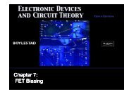
Constant-Gain <strong>Amp</strong>lifier<br />
Noninverting Version<br />
Electronic Devices and Circuit Theory, 10/e<br />
Robert L. Boylestad and Louis Nashelsky<br />
4<br />
Copyright ©2009 by Pearson Education, Inc.<br />
Upper Saddle River, New Jersey 07458 • All rights reserved.
Multiple-Stage Gains<br />
The total gain (3-stages) is given by:<br />
or<br />
A = A1A2A3<br />
⎛ R ⎞ ⎞ ⎞<br />
⎜<br />
⎛ ⎟⎜<br />
⎛ = ⎜ +<br />
f<br />
R<br />
⎟ −<br />
f<br />
R −<br />
f<br />
A 1<br />
⎟<br />
⎝ R ⎠⎝<br />
R2 ⎠⎝<br />
R3<br />
1<br />
⎠<br />
Electronic Devices and Circuit Theory, 10/e<br />
Robert L. Boylestad and Louis Nashelsky<br />
5<br />
Copyright ©2009 by Pearson Education, Inc.<br />
Upper Saddle River, New Jersey 07458 • All rights reserved.
Voltage Summing<br />
The output is <strong>th</strong>e sum<br />
of individual signals<br />
times <strong>th</strong>e gain:<br />
V<br />
o<br />
R<br />
⎜⎛<br />
f<br />
R<br />
f<br />
R<br />
f<br />
= −⎜⎜<br />
V1<br />
+<br />
V2<br />
+<br />
V3<br />
⎝ R1<br />
R 2 R 3<br />
⎟⎞<br />
⎟⎟<br />
⎠<br />
[Formula 14.3]<br />
Electronic Devices and Circuit Theory, 10/e<br />
Robert L. Boylestad and Louis Nashelsky<br />
6<br />
Copyright ©2009 by Pearson Education, Inc.<br />
Upper Saddle River, New Jersey 07458 • All rights reserved.
Voltage Buffer<br />
Any amplifier wi<strong>th</strong> no gain or loss is called a unity gain<br />
amplifier.<br />
The advantages of using a unity gain amplifier:<br />
• Very high input impedance<br />
• Very low output impedance<br />
Realistically <strong>th</strong>ese circuits<br />
are designed using equal<br />
resistors (R 1 = R f ) to avoid<br />
problems wi<strong>th</strong> offset<br />
voltages.<br />
Electronic Devices and Circuit Theory, 10/e<br />
Robert L. Boylestad and Louis Nashelsky<br />
7<br />
Copyright ©2009 by Pearson Education, Inc.<br />
Upper Saddle River, New Jersey 07458 • All rights reserved.
Controlled Sources<br />
Voltage-controlled voltage source<br />
Voltage-controlled current source<br />
Current-controlled voltage source<br />
Current-controlled current source<br />
Electronic Devices and Circuit Theory, 10/e<br />
Robert L. Boylestad and Louis Nashelsky<br />
8<br />
Copyright ©2009 by Pearson Education, Inc.<br />
Upper Saddle River, New Jersey 07458 • All rights reserved.
Voltage-Controlled Voltage Source<br />
The output voltage<br />
is <strong>th</strong>e gain times <strong>th</strong>e<br />
input voltage. What<br />
makes an op-amp<br />
different from o<strong>th</strong>er<br />
amplifiers is its<br />
impedance<br />
char<strong>ac</strong>teristics and<br />
gain calculations<br />
<strong>th</strong>at depend solely<br />
on external<br />
resistors.<br />
Noninverting <strong>Amp</strong>lifier Version<br />
more…<br />
Electronic Devices and Circuit Theory, 10/e<br />
Robert L. Boylestad and Louis Nashelsky<br />
9<br />
Copyright ©2009 by Pearson Education, Inc.<br />
Upper Saddle River, New Jersey 07458 • All rights reserved.
Voltage-Controlled Voltage Source<br />
The output voltage<br />
is <strong>th</strong>e gain times <strong>th</strong>e<br />
input voltage. What<br />
makes an op-amp<br />
different from o<strong>th</strong>er<br />
amplifiers is its<br />
impedance<br />
char<strong>ac</strong>teristics and<br />
gain calculations<br />
<strong>th</strong>at depend solely<br />
on external<br />
resistors.<br />
Inverting <strong>Amp</strong>lifier Version<br />
Electronic Devices and Circuit Theory, 10/e<br />
Robert L. Boylestad and Louis Nashelsky<br />
10<br />
Copyright ©2009 by Pearson Education, Inc.<br />
Upper Saddle River, New Jersey 07458 • All rights reserved.
Voltage-Controlled Current Source<br />
The output current<br />
is:<br />
V1<br />
I o<br />
=<br />
=<br />
R<br />
1<br />
kV<br />
1<br />
Electronic Devices and Circuit Theory, 10/e<br />
Robert L. Boylestad and Louis Nashelsky<br />
<strong>11</strong><br />
Copyright ©2009 by Pearson Education, Inc.<br />
Upper Saddle River, New Jersey 07458 • All rights reserved.
Current-Controlled Controlled Voltage Source<br />
This is simply ano<strong>th</strong>er way<br />
of applying <strong>th</strong>e op-amp<br />
operation. Whe<strong>th</strong>er <strong>th</strong>e<br />
input is a current<br />
determined by V in /R 1 or as<br />
I 1 :<br />
or<br />
V<br />
out<br />
=<br />
−<br />
R<br />
f<br />
R<br />
1<br />
V = −I<br />
out<br />
1<br />
V<br />
R<br />
in<br />
L<br />
Electronic Devices and Circuit Theory, 10/e<br />
Robert L. Boylestad and Louis Nashelsky<br />
12<br />
Copyright ©2009 by Pearson Education, Inc.<br />
Upper Saddle River, New Jersey 07458 • All rights reserved.
Current-Controlled Controlled Current Source<br />
This circuit may appear<br />
more complicated <strong>th</strong>an<br />
<strong>th</strong>e o<strong>th</strong>ers but it is really<br />
<strong>th</strong>e same <strong>th</strong>ing.<br />
V<br />
V<br />
V<br />
out<br />
out<br />
R<br />
f<br />
out<br />
R<br />
f<br />
⎛<br />
Rf<br />
⎞<br />
= −⎜⎜<br />
V<br />
R ⎟⎟<br />
⎝ in ⎠<br />
V<br />
= −<br />
in<br />
R || R<br />
V<br />
= −<br />
R<br />
1<br />
in<br />
in<br />
in<br />
2<br />
I<br />
I<br />
I<br />
I<br />
o<br />
o<br />
o<br />
o<br />
=<br />
=<br />
=<br />
=<br />
Vin<br />
−<br />
R || R<br />
−V<br />
in<br />
V<br />
−<br />
R<br />
1<br />
in<br />
1<br />
⎛<br />
−I⎜⎜<br />
1 +<br />
⎝<br />
⎛ R<br />
⎜⎜<br />
⎝ R<br />
1<br />
1<br />
R1<br />
R<br />
⎜⎜<br />
⎛ +<br />
⎝ R 2<br />
R<br />
R<br />
2<br />
+ R<br />
× R<br />
1<br />
2<br />
2<br />
2<br />
⎞<br />
⎟⎟<br />
⎠<br />
2<br />
⎞<br />
⎟⎟<br />
⎠<br />
⎞<br />
⎟⎟ = kI<br />
⎠<br />
Electronic Devices and Circuit Theory, 10/e<br />
Robert L. Boylestad and Louis Nashelsky<br />
13<br />
Copyright ©2009 by Pearson Education, Inc.<br />
Upper Saddle River, New Jersey 07458 • All rights reserved.
Instrumentation Circuits<br />
Some examples of instrumentation circuits using opamps:<br />
• Display driver<br />
• Instrumentation amplifier<br />
Electronic Devices and Circuit Theory, 10/e<br />
Robert L. Boylestad and Louis Nashelsky<br />
14<br />
Copyright ©2009 by Pearson Education, Inc.<br />
Upper Saddle River, New Jersey 07458 • All rights reserved.
Display Driver<br />
Electronic Devices and Circuit Theory, 10/e<br />
Robert L. Boylestad and Louis Nashelsky<br />
15<br />
Copyright ©2009 by Pearson Education, Inc.<br />
Upper Saddle River, New Jersey 07458 • All rights reserved.
Instrumentation <strong>Amp</strong>lifier<br />
For all Rs at <strong>th</strong>e same value (except R p ):<br />
V<br />
o<br />
=<br />
⎛<br />
⎜⎜ 1 +<br />
⎝<br />
2R<br />
R<br />
P<br />
⎞<br />
⎟⎟<br />
⎠<br />
( V − V ) = k( V − V )<br />
1<br />
2<br />
1<br />
2<br />
Electronic Devices and Circuit Theory, 10/e<br />
Robert L. Boylestad and Louis Nashelsky<br />
16<br />
Copyright ©2009 by Pearson Education, Inc.<br />
Upper Saddle River, New Jersey 07458 • All rights reserved.
Active Filters<br />
Adding cap<strong>ac</strong>itors to op-amp circuits provides external control of <strong>th</strong>e<br />
cutoff frequencies. The op-amp <strong>ac</strong>tive filter provides controllable<br />
cutoff frequencies and controllable gain.<br />
• Low-pass filter<br />
• High-pass filter<br />
• Bandpass filter<br />
Electronic Devices and Circuit Theory, 10/e<br />
Robert L. Boylestad and Louis Nashelsky<br />
17<br />
Copyright ©2009 by Pearson Education, Inc.<br />
Upper Saddle River, New Jersey 07458 • All rights reserved.
Low-Pass Filter—First<br />
First-Order<br />
The upper cutoff frequency<br />
and voltage gain are given<br />
by:<br />
f =<br />
OH<br />
1<br />
2πR<br />
1<br />
C<br />
1<br />
A = 1 +<br />
v<br />
R<br />
R<br />
f<br />
1<br />
Electronic Devices and Circuit Theory, 10/e<br />
Robert L. Boylestad and Louis Nashelsky<br />
18<br />
Copyright ©2009 by Pearson Education, Inc.<br />
Upper Saddle River, New Jersey 07458 • All rights reserved.
Low-Pass Filter—Second<br />
Second-Order<br />
The roll-off can be made steeper by adding more RC networks.<br />
Electronic Devices and Circuit Theory, 10/e<br />
Robert L. Boylestad and Louis Nashelsky<br />
19<br />
Copyright ©2009 by Pearson Education, Inc.<br />
Upper Saddle River, New Jersey 07458 • All rights reserved.
High-Pass Filter<br />
The cutoff frequency is determined by:<br />
f =<br />
OL<br />
1<br />
2πR<br />
1<br />
C<br />
1<br />
Electronic Devices and Circuit Theory, 10/e<br />
Robert L. Boylestad and Louis Nashelsky<br />
20<br />
Copyright ©2009 by Pearson Education, Inc.<br />
Upper Saddle River, New Jersey 07458 • All rights reserved.
Bandpass Filter<br />
There are two cutoff<br />
frequencies: upper and<br />
lower. They can be<br />
calculated using <strong>th</strong>e same<br />
low-pass cutoff and highpass<br />
cutoff frequency<br />
formulas in <strong>th</strong>e<br />
appropriate sections.<br />
Electronic Devices and Circuit Theory, 10/e<br />
Robert L. Boylestad and Louis Nashelsky<br />
21<br />
Copyright ©2009 by Pearson Education, Inc.<br />
Upper Saddle River, New Jersey 07458 • All rights reserved.