the digital emily project - ICT Graphics Lab
the digital emily project - ICT Graphics Lab
the digital emily project - ICT Graphics Lab

Create successful ePaper yourself
Turn your PDF publications into a flip-book with our unique Google optimized e-Paper software.
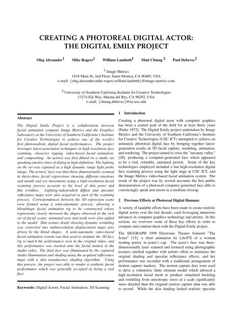
CREATING A PHOTOREAL DIGITAL ACTOR:<br />
THE DIGITAL EMILY PROJECT<br />
Oleg Alexander 1 Mike Rogers 1 William Lambeth 1 Matt Chiang 2 Paul Debevec 2<br />
1 Image Metrics<br />
1918 Main St, 2nd Floor, Santa Monica, CA 90405, USA<br />
e-mail: {oleg.alexander,mike.rogers,william.lambeth}@image-metrics.com<br />
2 University of Sou<strong>the</strong>rn California Institute for Creative Technologies<br />
13274 Fiji Way, Marina del Rey, CA 90292, USA<br />
e-mail: {chiang,debevec}@ict.usc.edu<br />
Abstract<br />
The Digital Emily Project is a collaboration between<br />
facial animation company Image Metrics and <strong>the</strong> <strong>Graphics</strong><br />
<strong>Lab</strong>oratory at <strong>the</strong> University of Sou<strong>the</strong>rn California’s Institute<br />
for Creative Technologies to achieve one of <strong>the</strong> world’s<br />
first photorealistic <strong>digital</strong> facial performances. The <strong>project</strong><br />
leverages latest-generation techniques in high-resolution face<br />
scanning, character rigging, video-based facial animation,<br />
and compositing. An actress was first filmed on a studio set<br />
speaking emotive lines of dialog in high definition. The lighting<br />
on <strong>the</strong> set was captured as a high dynamic range light probe<br />
image. The actress’ face was <strong>the</strong>n three-dimensionally scanned<br />
in thirty-three facial expressions showing different emotions<br />
and mouth and eye movements using a high-resolution facial<br />
scanning process accurate to <strong>the</strong> level of skin pores and<br />
fine wrinkles. Lighting-independent diffuse and specular<br />
reflectance maps were also acquired as part of <strong>the</strong> scanning<br />
process. Correspondences between <strong>the</strong> 3D expression scans<br />
were formed using a semi-automatic process, allowing a<br />
blendshape facial animation rig to be constructed whose<br />
expressions closely mirrored <strong>the</strong> shapes observed in <strong>the</strong> rich<br />
set of facial scans; animated eyes and teeth were also added<br />
to <strong>the</strong> model. Skin texture detail showing dynamic wrinkling<br />
was converted into multiresolution displacement maps also<br />
driven by <strong>the</strong> blend shapes. A semi-automatic video-based<br />
facial animation system was <strong>the</strong>n used to animate <strong>the</strong> 3D face<br />
rig to match <strong>the</strong> performance seen in <strong>the</strong> original video, and<br />
this performance was tracked onto <strong>the</strong> facial motion in <strong>the</strong><br />
studio video. The final face was illuminated by <strong>the</strong> captured<br />
studio illumination and shading using <strong>the</strong> acquired reflectance<br />
maps with a skin translucency shading algorithm. Using<br />
this process, <strong>the</strong> <strong>project</strong> was able to render a syn<strong>the</strong>tic facial<br />
performance which was generally accepted as being a real<br />
face.<br />
Keywords: Digital Actors; Facial Animation; 3D Scanning<br />
1 Introduction<br />
Creating a photoreal <strong>digital</strong> actor with computer graphics<br />
has been a central goal of <strong>the</strong> field for at least thirty years<br />
[Parke 1972]. The Digital Emily <strong>project</strong> undertaken by Image<br />
Metrics and <strong>the</strong> University of Sou<strong>the</strong>rn California’s Institute<br />
for Creative Technologies (USC <strong>ICT</strong>) attempted to achieve an<br />
animated, photoreal <strong>digital</strong> face by bringing toge<strong>the</strong>r latestgeneration<br />
results in 3D facial capture, modeling, animation,<br />
and rendering. The <strong>project</strong> aimed to cross <strong>the</strong> ”uncanny valley”<br />
[20], producing a computer-generated face which appeared<br />
to be a real, relatable, animated person. Some of <strong>the</strong> key<br />
technologies employed included a fast high-resolution <strong>digital</strong><br />
face scanning process using <strong>the</strong> light stage at USC <strong>ICT</strong>, and<br />
<strong>the</strong> Image Metrics video-based facial animation system. The<br />
result of <strong>the</strong> <strong>project</strong> was by several accounts <strong>the</strong> first public<br />
demonstration of a photoreal computer-generated face able to<br />
convincingly speak and emote in a medium closeup.<br />
2 Previous Efforts at Photoreal Digital Humans<br />
A variety of laudable efforts have been made to create realistic<br />
<strong>digital</strong> actors over <strong>the</strong> last decade, each leveraging numerous<br />
advances in computer graphics technology and artistry. In this<br />
section, we overview some of <strong>the</strong>se key efforts in order to<br />
compare and contrast <strong>the</strong>m with <strong>the</strong> Digital Emily <strong>project</strong>.<br />
The SIGGRAPH 1999 Electronic Theater featured ”The<br />
Jester” [15], a short animation by Life/FX of a woman<br />
reading poetry in jester’s cap. The actor’s face was threedimensionally<br />
laser scanned and textured using photographic<br />
textures stitched toge<strong>the</strong>r with artistic effort to minimize <strong>the</strong><br />
original shading and specular reflectance effects, and her<br />
performance was recorded with a traditional arrangement of<br />
motion capture markers. The motion capture dots were used<br />
to drive a volumetric finite element model which allowed a<br />
high-resolution facial mesh to produce simulated buckling<br />
and wrinkling from anisotropic stress at a scale significantly<br />
more detailed than <strong>the</strong> original motion capture data was able<br />
to record. While <strong>the</strong> skin shading lacked realistic specular
eflectance and pore detail, <strong>the</strong> face conveyed realistic motion<br />
and emotion in significant part due to <strong>the</strong> skin dynamics<br />
model. The process was later extended with significant<br />
additional artistic effort to create an aged version of <strong>the</strong> actor<br />
in a follow-up animation ”Young at Heart”.<br />
Disney’s ”Human Face Project” developed technology to<br />
show an older actor encountering a younger version of<br />
himself [27, 12]. A facial mold of <strong>the</strong> actor’s face was taken<br />
and <strong>the</strong> resulting cast was scanned using a high-resolution<br />
face scanning process, and twenty-two Cyberware scans in<br />
various expressions were also acquired. A medium-resolution<br />
animated facial rig was sculpted to mimic <strong>the</strong> expression<br />
scans used as reference. A multi-camera facial capture<br />
setup was employed to film <strong>the</strong> face under relatively flat<br />
cross-polarized lighting. Polarization difference images<br />
isolating specular reflections of <strong>the</strong> face [5] were acquired<br />
to reveal high-resolution texture detail, and analysis of this<br />
texture was used to add skin pores and fine wrinkle detail as<br />
displacement maps to <strong>the</strong> scans. Optical flow performed on<br />
video of <strong>the</strong> actor’s performance was used to drive <strong>the</strong> <strong>digital</strong><br />
face, achieving remarkably close matches to <strong>the</strong> original<br />
performance. A younger version of <strong>the</strong> actor was artistically<br />
modeled based on photographs of him in his twenties. HDR<br />
lighting information was captured on set so that <strong>the</strong> <strong>digital</strong><br />
actor could be rendered with image-based lighting [4] to match<br />
<strong>the</strong> on-set illumination. Final renderings achieved convincing<br />
facial motion and lighting in a two-shot but less convincing<br />
facial reflectance; a significant problem was that no simulation<br />
of <strong>the</strong> skin’s translucency [14] had been performed.<br />
The Matrix Sequels (2003) used <strong>digital</strong> actors for many scenes<br />
where Keanu Reeves acrobatically fights many copies of Hugo<br />
Weaving. High-quality facial casts of Reeves and Weaving<br />
were acquired and scanned with a high-resolution laser<br />
scanning system (<strong>the</strong> XYZRGB system based on technology<br />
from <strong>the</strong> Canadian National Research Council) to provide<br />
3D geometry accurate to <strong>the</strong> level of skin pores and fine<br />
wrinkles. A six-camera high-definition facial capture rig<br />
was used to film facial performance clips of <strong>the</strong> actors under<br />
relatively flat illumination. The six views in <strong>the</strong> video were<br />
used to animate a facial rig of <strong>the</strong> actor and, as in [10], to<br />
provide time-varying texture maps for <strong>the</strong> dynamic facial<br />
appearance. Still renderings using image-based lighting [4]<br />
and a texture-space approximation to subsurface scattering<br />
[2] showed notably realistic faces which greatly benefitted<br />
from <strong>the</strong> high-resolution geometric detail texture found in <strong>the</strong><br />
XYZRGB scans. However, <strong>the</strong> animated facial performances<br />
in <strong>the</strong> film were shown in relatively wide shots and exhibited<br />
less realistic skin reflectance, perhaps having lost some<br />
appearance of geometric detail during normal map filtering.<br />
The animated texture maps, however, provided a convincing<br />
degree of dynamic shading and albedo changes to <strong>the</strong> facial<br />
performances. A tradeoff to <strong>the</strong> use of video textures is that<br />
<strong>the</strong> facial model could not easily generate novel performances<br />
unless <strong>the</strong>y too were captured in <strong>the</strong> complete performance<br />
capture setup.<br />
Spider Man 2 (2004) built <strong>digital</strong> stunt doubles for villain Doc<br />
Ock (Alfred Molina) and hero Spider-Man (Tobey Maguire)<br />
using facial reflectance scans in USC <strong>ICT</strong>’s Light Stage 2<br />
device [24]. Each actor was filmed with four synchronized<br />
35mm film cameras in several facial expressions from 480<br />
lighting directions. Colorspace techniques as in [5] were used<br />
to separate diffuse and specular reflections. The relightable<br />
texture information was <strong>project</strong>ed onto a 3D facial rig based<br />
on geometry from a traditional laser scan, and illuminated<br />
variously by HDRI image-based lighting [4] and traditional<br />
CG light sources using a custom shading algorithm for<br />
approximately 40 <strong>digital</strong> double shots. Using additional<br />
cameras, <strong>the</strong> technique was also used to construct <strong>digital</strong><br />
actors for Superman Returns (2006), Spider Man 3 (2007), and<br />
Hancock (2008). Due to <strong>the</strong> extensive reflectance information<br />
collected, <strong>the</strong> technique yielded realistic facial reflectance<br />
for <strong>the</strong> <strong>digital</strong> characters, including close-up shots with mild<br />
degrees of facial animation, especially in Superman Returns.<br />
However, results of <strong>the</strong> process did not demonstrate emotive<br />
facial performances in closeup; significant facial animation<br />
was shown only in wide shots.<br />
Beowulf (2007) used a multitude of <strong>digital</strong> characters for a<br />
fully computer-rendered film. The performance capture based<br />
film following <strong>the</strong> approach of <strong>the</strong> 2001 film Final Fantasy<br />
of constructing as detailed characters as possible and <strong>the</strong>n<br />
driving <strong>the</strong>m with motion capture, keyframe animation, and<br />
simulation. Beowulf substantially advanced <strong>the</strong> state of <strong>the</strong><br />
art in this area by leveraging greater motion capture fidelity<br />
and performance volume, employing more complex lighting<br />
simulation, and using better skin shading techniques. While<br />
some characters were based closely in appearance <strong>the</strong>ir voice<br />
and motion capture actors (e.g. Angelina Jolie and Anthony<br />
Hopkins), o<strong>the</strong>r characters bore little resemblance (e.g. Ray<br />
Winstone), requiring additional artistic effort to model <strong>the</strong>m.<br />
Static renderings of <strong>the</strong> faces achieved impressive levels<br />
of realism, although <strong>the</strong> single-layer subsurface scattering<br />
model produced a somewhat ”waxy” appearance. Also,<br />
<strong>the</strong> artist-driven character creation process did not leverage<br />
high-resolution 3D scans of each actor in a multitude of facial<br />
expressions. According to Variety [3], <strong>the</strong> ”digitized figures<br />
in ’Beowulf’ look eerily close to storefront mannequins ...<br />
suspended somewhere between live-action and animation,<br />
fairy tale and videogame.”<br />
The Curious Case of Benjamin Button (2008) was <strong>the</strong> first<br />
feature film to feature a photoreal human virtual character.<br />
The aged version of Brad Pitt seen in <strong>the</strong> film’s first 52<br />
minutes was created by visual effects studio Digital Domain<br />
leveraging ”recently developed offerings from Mova, Image<br />
Metrics, and <strong>the</strong> [USC] Institute for Creative Technologies”<br />
[23]. Silcone maquettes of Brad Pitt as an old man were<br />
constructed by Kazuhiro Tsuji at Rick Baker’s makeup studio<br />
and used as <strong>the</strong> basis for <strong>the</strong> <strong>digital</strong> character. Detailed facial<br />
reflectance capture was performed for <strong>the</strong> age 70 maquette in<br />
USC <strong>ICT</strong>’s Light Stage 5 device [26] from eight angles and 156<br />
lighting directions. Medium-resolution meshes of Brad Pitt’s<br />
face in a multitude of facial expressions were captured using
Mova’s Contour facial capture system [22], using a mottled<br />
pattern of glow-in-<strong>the</strong>-dark makeup to create facial geometry<br />
from multi-view stereo. Digital Domain used special software<br />
tools and manual effort to create a rigged <strong>digital</strong> character<br />
whose articulations were based closely on <strong>the</strong> facial shapes<br />
captured in <strong>the</strong> Mova system. Image Metrics’ video-based<br />
facial animation system was used to provide animation curves<br />
for <strong>the</strong> Benjamin facial rigs by analyzing frontal, flat-lit video<br />
of Brad Pitt performing each scene of <strong>the</strong> film in a studio;<br />
<strong>the</strong>se animation curves were frequently refined by animators<br />
at Digital Domain to create <strong>the</strong> final performances seen in <strong>the</strong><br />
film. Extensive HDRI documentation was taken on each film<br />
set so that advanced Image-Based Lighting techniques based<br />
on [4] could be used to render <strong>the</strong> character with matching<br />
illumination to <strong>the</strong> on-set lighting. Image-based relighting<br />
techniques as in [5] were used to simulate <strong>the</strong> reflectance of <strong>the</strong><br />
scanned maquette in each illumination environment as crossvalidation<br />
of <strong>the</strong> <strong>digital</strong> character’s lighting and skin shaders.<br />
The final renderings were accurately tracked onto <strong>the</strong> heads<br />
of slight, aged actors playing <strong>the</strong> body of Benjamin in each<br />
scene. The quality of <strong>the</strong> character was universally lauded<br />
as a breakthrough in computer graphics, winning <strong>the</strong> film an<br />
Academy Award for Best Visual Effects. An estimate of more<br />
than two hundred person-years of effort was reportedly spent<br />
[23] creating <strong>the</strong> character in this groundbreaking work.<br />
3 Acquiring high-resolution scans of <strong>the</strong> actor in various<br />
facial expressions<br />
Emily O’Brien, an Emmy-nominated actress from <strong>the</strong><br />
American daytime drama ”The Young and <strong>the</strong> Restless”, was<br />
cast for <strong>the</strong> <strong>project</strong>. After being filmed seated describing<br />
aspects of <strong>the</strong> Image Metrics facial animation process on an<br />
informal studio set, Emily came to USC <strong>ICT</strong> to be scanned in<br />
its Light Stage 5 device on <strong>the</strong> afternoon of March 24, 2008. A<br />
set of 40 small facial dots were applied to Emily’s face with a<br />
dark makeup pencil to assist with facial modeling. Emily <strong>the</strong>n<br />
entered Light Stage 5 for approximately 90 minutes during<br />
which data for thirty-seven high-resolution facial scans were<br />
acquired. Fig. 1 shows Emily in <strong>the</strong> light stage during a scan,<br />
with all 156 of its white LED lights turned on.<br />
The light stage scanning process used for Digital Emily was<br />
described in [18]. In contrast to earlier light stage processes<br />
(e.g. [5, 11]), which photograph <strong>the</strong> face under hundreds of<br />
illumination directions, this newer capture process requires<br />
only fifteen photographs of <strong>the</strong> face under different lighting<br />
conditions as seen in Fig. 2 to capture geometry and reflectance<br />
information for a face. The photos are taken with a stereo pair<br />
of Canon EOS 1D Mark III <strong>digital</strong> still cameras, and <strong>the</strong> images<br />
are sufficiently few so that <strong>the</strong>y can be captured in <strong>the</strong> cameras’<br />
”burst mode” in under three seconds, before any data needs to<br />
be written to <strong>the</strong> compact flash cards.<br />
Figure 1: Actress Emily O’Brien being scanned in Light<br />
Stage 5 at USC <strong>ICT</strong> for <strong>the</strong> Digital Emily <strong>project</strong>.<br />
3.1 Estimating Subsurface and Specular Albedo and<br />
Normals<br />
Most of <strong>the</strong> images are shot with essentially every light in<br />
<strong>the</strong> light stage turned on, but with different gradations of<br />
brightness. All of <strong>the</strong> light stage lights have linear polarizer<br />
film placed on <strong>the</strong>m, affixed in a special pattern of orientations,<br />
which permits <strong>the</strong> measurement of <strong>the</strong> specular and subsurface<br />
reflectance components of <strong>the</strong> face independently by changing<br />
<strong>the</strong> orientation of a polarizer on <strong>the</strong> camera.<br />
The top two rows of Fig. 2 show Emily’s face under<br />
four spherical gradient illumination conditions and <strong>the</strong>n a<br />
point-light condition, and all of <strong>the</strong> images in this row are<br />
cross-polarized to eliminate <strong>the</strong> shine from <strong>the</strong> surface of<br />
her skin – her specular component. What remains is <strong>the</strong><br />
skin-colored ”subsurface” reflection, often referred to as <strong>the</strong><br />
”diffuse” component. This is light which scatters within <strong>the</strong><br />
skin enough to become depolarized before re-emerging. Since<br />
this light is depolarized, approximately half of this light can<br />
pass through <strong>the</strong> horizontal polarizer on <strong>the</strong> camera. The top<br />
right image is lit by a frontal flash, also cross-polarizing out<br />
<strong>the</strong> specular reflection.<br />
The middle row of Fig. 2 shows parallel-polarized images<br />
of <strong>the</strong> face, where <strong>the</strong> polarizer on <strong>the</strong> camera is rotated<br />
vertically so that <strong>the</strong> specular reflection returns, in double<br />
strength compared to <strong>the</strong> attenuated subsurface reflection. We<br />
can <strong>the</strong>n reveal <strong>the</strong> specular reflection on its own by subtracting<br />
<strong>the</strong> first row of images from <strong>the</strong> second row, yielding <strong>the</strong><br />
specular-only images shown in Fig. 3.<br />
Fig. 4(a) is a closeup of <strong>the</strong> ”diffuse-all” image of Emily.<br />
Every light in <strong>the</strong> light stage is turned on to equal intensity, and<br />
<strong>the</strong> polarizer on <strong>the</strong> camera is oriented to block <strong>the</strong> specular<br />
reflection from every single one of <strong>the</strong> polarized LED light<br />
sources. Even <strong>the</strong> highlights of <strong>the</strong> lights in Emily’s eyes are<br />
eliminated.<br />
This is about as flat-lit an image of a person’s face as can<br />
conceivably be photographed, and thus it is nearly a perfect
(a) (b) (c)<br />
Figure 4: Closeups of Emily’s (a) cross-polarized subsurface<br />
component, (b) parallel-polarized subsurface plus specular<br />
component, and (c) isolated specular component formed by<br />
subtracting (a) from (b). The black makeup dots on her<br />
face are easily removed <strong>digital</strong>ly and help with aligning and<br />
corresponding her scans.<br />
Figure 2: The fifteen photographs taken by a frontal stereo<br />
pair of cameras for each Emily scan. The photo sets, taken<br />
in under three seconds, record Emily’s diffuse albedo and<br />
normals (top row), specular albedo and normals (second<br />
row), and base 3D geometry (bottom row).<br />
Figure 3: Emily’s specular component under <strong>the</strong> four<br />
gradient lighting conditions (all, left, top, front) and single<br />
frontal flash condition, obtained by subtracting <strong>the</strong> crosspolarized<br />
images from <strong>the</strong> parallel-polarized images.<br />
image to use as <strong>the</strong> diffuse texture map for <strong>the</strong> face in building<br />
a <strong>digital</strong> actor. The one issue is that it is affected to some<br />
extent by self-shadowing and interreflections, making <strong>the</strong><br />
concavities around <strong>the</strong> eyes, under <strong>the</strong> nose, and between<br />
<strong>the</strong> lips appear somewhat darker and more color-saturated<br />
than it inherently is. Depending on <strong>the</strong> rendering technique<br />
chosen, having <strong>the</strong>se effects of occlusion and interreflection<br />
”baked in” to <strong>the</strong> texture map is ei<strong>the</strong>r a problem or an<br />
advantage. For real-time rendering, <strong>the</strong> effects can add realism<br />
(as if <strong>the</strong> environmental light were entirely uniform) given<br />
that simulating <strong>the</strong>m accurately might be computationally<br />
prohibitive. If new lighting is being simulated on <strong>the</strong> face<br />
using a more accurate global illumination technique, <strong>the</strong>n it<br />
is problematic to calculate self-shadowing of a surface whose<br />
texture map already has self-shadowing present; likewise<br />
for interreflections. In this case, one could perform inverse<br />
rendering by using <strong>the</strong> actor’s 3D geometry and approximate<br />
reflectance to predict <strong>the</strong> effects of self-shadowing and/or<br />
interreflections, and <strong>the</strong>n divide <strong>the</strong>se effects out of <strong>the</strong> texture<br />
image as in [6].<br />
Fig. 4(a) also shows <strong>the</strong> makeup dots we put on Emily’s face<br />
which help us to align <strong>the</strong> images in <strong>the</strong> event <strong>the</strong>re is any<br />
drift in her position or expression over <strong>the</strong> fifteen images; <strong>the</strong>y<br />
are relatively easy to remove <strong>digital</strong>ly. Emily was extremely<br />
good at staying still for <strong>the</strong> three-second scans and many of<br />
her datasets required no motion compensation at all. (Faster<br />
capture times are already possible: 24fps capture of such data<br />
using high-speed video cameras is described in [19]).<br />
The shinier image in Fig. 4(b) is also lit by all of <strong>the</strong> light stage<br />
lights, but <strong>the</strong> orientation of <strong>the</strong> polarizer has been turned 90<br />
degrees which allows <strong>the</strong> specular reflections to return. Her<br />
skin exhibits a specular sheen, and <strong>the</strong> reflections of <strong>the</strong> lights<br />
are now evident in her eyes. In fact, <strong>the</strong> specular reflection<br />
is seen at double <strong>the</strong> strength of <strong>the</strong> subsurface (or diffuse)<br />
reflection, since <strong>the</strong> polarizer on <strong>the</strong> camera blocks about half<br />
of <strong>the</strong> unpolarized subsurface reflection.<br />
Fig. 4(b) shows <strong>the</strong> combined effect of specular reflection<br />
and subsurface reflection. For modeling facial reflectance, we<br />
would ideally observe <strong>the</strong> specular reflection independently.<br />
As a useful alternative, we can simply subtract <strong>the</strong> diffuseonly<br />
image Fig. 4(a) from this one. Taking <strong>the</strong> difference<br />
between <strong>the</strong> diffuse-only image and <strong>the</strong> diffuse-plus-specular<br />
image yields an image of primarily <strong>the</strong> specular reflection of<br />
<strong>the</strong> face as in 4(c). A polarization difference process was used<br />
previously for facial reflectance analysis in [5], but only for<br />
a single point light source and not for <strong>the</strong> entire sphere of<br />
illumination. The image is mostly colorless since this light<br />
has reflected specularly off <strong>the</strong> surface of <strong>the</strong> skin, ra<strong>the</strong>r<br />
than entering <strong>the</strong> skin and having its blue and green colors<br />
significantly absorbed by skin pigments and blood before<br />
reflecting back out.<br />
This image provides a useful starting point for building a <strong>digital</strong><br />
character’s specular intensity map, or ”spec map”; it shows<br />
for each pixel <strong>the</strong> intensity of <strong>the</strong> specular reflection at that<br />
pixel. However, <strong>the</strong> specular reflection becomes amplified near<br />
grazing angles, such as at <strong>the</strong> sides of <strong>the</strong> face according to<br />
<strong>the</strong> denominator of Fresnel’s equations. We generally model<br />
and compensate for this effect using Fresnel’s equations but<br />
also discount regions of <strong>the</strong> face at extreme grazing angles.
The image also includes some of <strong>the</strong> effects of ”reflection<br />
occlusion” [16]. The sides of <strong>the</strong> nose and innermost contour<br />
of <strong>the</strong> lips appear to have no specular reflection since selfshadowing<br />
prevents <strong>the</strong> lights from reflecting in <strong>the</strong>se angles.<br />
This effect can be an asset for real-time rendering, but should<br />
be manually painted out for offline rendering.<br />
Recent work [9] reports that this sort of polarization difference<br />
image also contains <strong>the</strong> effects of single scattering, wherein<br />
light refracts into <strong>the</strong> skin but scatters exactly once before<br />
refracting back toward <strong>the</strong> camera. Such light can pick up<br />
<strong>the</strong> color of <strong>the</strong> skin’s melanocytes, adding some color to <strong>the</strong><br />
specular image. However, <strong>the</strong> image is dominated by <strong>the</strong><br />
specular component’s first-surface reflection, which allows us<br />
to reconstruct high-resolution facial geometry.<br />
The four difference images of <strong>the</strong> face’s specular reflection<br />
under <strong>the</strong> gradient illumination patterns (Fig. 3) let us derive<br />
a high-resolution normal map for <strong>the</strong> face: a map of its local<br />
surface orientation vector at each pixel. If we examine <strong>the</strong><br />
intensity of one pixel across this four-image sequence, its<br />
brightness in <strong>the</strong> X, Y, and Z images divided by its brightness<br />
in <strong>the</strong> fully-illuminated image uniquely encodes <strong>the</strong> direction<br />
of <strong>the</strong> light stage reflected in that pixel. From <strong>the</strong> simple<br />
formula in [18] involving image ratios, we can derive <strong>the</strong><br />
reflection vector at each pixel, and from <strong>the</strong> camera orientations<br />
(calibrated with <strong>the</strong> technique of [28]) we also know <strong>the</strong> view<br />
vector.<br />
Figure 5: The specular normal map for one of Emily’s<br />
expressions derived from <strong>the</strong> four specular reflection images<br />
under <strong>the</strong> gradient illumination patterns.<br />
Computing <strong>the</strong> vector halfway between <strong>the</strong> reflection vector<br />
and <strong>the</strong> view vector yields a surface normal estimate for <strong>the</strong><br />
face based on <strong>the</strong> specular reflection. Fig. 5 shows <strong>the</strong> face’s<br />
normal map visualized using <strong>the</strong> common color map where<br />
red, green and blue indicate <strong>the</strong> X, Y, and Z components of<br />
<strong>the</strong> surface normal. The normal map contains detail at <strong>the</strong><br />
level of skin pores and fine wrinkles. The point-lit polarization<br />
difference image (Fig. 3, far right) provides a visual indication<br />
of <strong>the</strong> BRDF’s specular lobe shape on <strong>the</strong> nose, forehead,<br />
cheeks, and lips. This image provides visual reference for<br />
choosing specular roughness parameters for <strong>the</strong> skin shaders.<br />
The image can also be used to drive a data-driven specular<br />
reflectance model as in [9].<br />
3.2 Deriving High-Resolution 3D Geometry<br />
The last set of images in <strong>the</strong> scanning process (Fig. 2, bottom<br />
row) are a set of colored stripe patterns from a video <strong>project</strong>or<br />
which allow a stereo correspondence algorithm to robustly<br />
compute pixel correspondences between <strong>the</strong> left and right<br />
viewpoints of <strong>the</strong> face. The <strong>project</strong>or is also cross-polarized<br />
so that <strong>the</strong> stereo pair of images consist of only subsurface<br />
reflection and lack specular highlights; such highlights<br />
would shift in position between <strong>the</strong> two viewpoints and thus<br />
complicate <strong>the</strong> stereo correspondence process. The patterns<br />
form a series of color-ramp stripes of different frequencies so<br />
that a given facial pixel receives a unique set of RGB irradiance<br />
values over <strong>the</strong> course of <strong>the</strong> sequence [17]. The first <strong>project</strong>ed<br />
image, showing full-on illumination, is used to divide out <strong>the</strong><br />
cross-polarized facial BRDF from <strong>the</strong> remaining stripe images;<br />
this also helps ensure that pixels in one camera have very<br />
nearly <strong>the</strong> same pixel values as in <strong>the</strong> o<strong>the</strong>r camera, facilitating<br />
correspondence. From <strong>the</strong>se correspondences and <strong>the</strong> camera<br />
calibration [28], we can triangulate a three-dimensional mesh<br />
of <strong>the</strong> face with vertices at each pixel, applying bilateral mesh<br />
denoising [8] to produce a smooth mesh without adding blur to<br />
geometric features. However, <strong>the</strong> surface resolution observable<br />
from <strong>the</strong> diffuse reflection of skin is limited by <strong>the</strong> scattering<br />
of <strong>the</strong> incident light beneath <strong>the</strong> skin. As a result, <strong>the</strong> geometry<br />
appears relatively smooth and lacks <strong>the</strong> skin texture detail that<br />
we wish to capture in our scans.<br />
We add in <strong>the</strong> skin texture detail by embossing <strong>the</strong> specular<br />
normal map onto <strong>the</strong> 3D mesh. By doing this, a highresolution<br />
version of <strong>the</strong> mesh is created and <strong>the</strong> vertices of<br />
each triangle are allowed to move forward and back until <strong>the</strong>y<br />
best exhibit <strong>the</strong> same surface normals as <strong>the</strong> normal map. The<br />
<strong>ICT</strong> <strong>Graphics</strong> <strong>Lab</strong> first described this process – using diffuse<br />
normals estimated in Light Stage 2 – in [13] 2001; more recent<br />
work in <strong>the</strong> area includes Nehab et al. [21].) This creates a<br />
notably high-resolution 3D scan, showing different skin texture<br />
detail clearly observable in different areas of <strong>the</strong> face (Fig. 6).<br />
3.3 Scanning a Multitude of Expressions<br />
Emily was captured in thirty-three different facial expressions<br />
based loosely on Paul Ekman’s Facial Action Coding System<br />
(FACS) [7] as seen in Fig. 7; fourteen of <strong>the</strong>se individual scans<br />
are shown in Fig. 8. By design, <strong>the</strong>re is a great deal of variety<br />
in <strong>the</strong> shape of her skin and <strong>the</strong> pose of her lips, eyes, and jaw<br />
across <strong>the</strong> scans. Emily was fortunately very good at staying<br />
still for all of <strong>the</strong> expressions. Two of <strong>the</strong> expressions, one<br />
with eyes closed and one with eyes open, were also scanned<br />
from <strong>the</strong> sides with Emily’s face rotated to <strong>the</strong> left and right<br />
as seen in <strong>the</strong> inset figures of <strong>the</strong> neutral-mouth-closed and<br />
neutral-mouth-open scans. This allowed us to merge toge<strong>the</strong>r<br />
a 3D model of <strong>the</strong> face with geometry stopping just short of<br />
her ears to create <strong>the</strong> complete ”master mesh” (Fig. 12(a)) and
(a)<br />
(b)<br />
Figure 6: (a) Facial geometry obtained from <strong>the</strong> diffuse<br />
(or subsurface) component of <strong>the</strong> reflection. (b) Far more<br />
detailed facial geometry obtained by embossing <strong>the</strong> specular<br />
normal map onto <strong>the</strong> diffuse geometry.<br />
to extrapolate full ear-to-ear geometry for each partial (frontalonly)<br />
facial scan as in Fig. 15(c).<br />
We note that building a <strong>digital</strong> actor from 3D scans of multiple<br />
facial expressions is a commonly practiced technique; for<br />
example, <strong>the</strong> Animatable Facial Reflectance Fields <strong>project</strong><br />
[11] followed this approach in scanning actress Jessica Vallot<br />
in approximately forty facial expressions. Going fur<strong>the</strong>r back,<br />
visual effects company Industrial Light + Magic acquired<br />
several Cyberware 3D scans of actress Mary Elizabeth<br />
Mastrantonio in different expressions to animate <strong>the</strong> face of<br />
<strong>the</strong> water creature in 1989’s The Abyss.<br />
3.4 Phenomena Observed in <strong>the</strong> Facial Scans<br />
The fourteen faces in Fig. 8 show a sampling of <strong>the</strong> highresolution<br />
scans taken of Emily in different facial expressions,<br />
and offer an opportunity to observe three-dimensional facial<br />
dynamics in more detail than has been previously easy to do.<br />
A great deal of dynamic behavior can be observed as a face<br />
moves, exemplified in <strong>the</strong> detailed images in Fig. 9. For<br />
example, <strong>the</strong> skin pore detail on <strong>the</strong> cheek in Fig. 9(a) changes<br />
dramatically when Emily pulls her mouth <strong>the</strong> side in Fig. 9(b):<br />
<strong>the</strong> pores significantly elongate and become shallower. When<br />
Emily stretches her face vertically, small veins pop out from<br />
her eyelid Fig. 9(c).<br />
When Emily raises her eyebrows, <strong>the</strong> relatively isotropic skin<br />
pores of her forehead transform into rows of fine wrinkles in<br />
Fig. 9(d) – her skin is too elastic to develop deep furrows.<br />
When she scowls in Fig. 9(e), indentations above her eyebrows<br />
appear where her muscles attach beneath <strong>the</strong> skin. And when<br />
she winces in Fig. 9(f), <strong>the</strong> muscles in her forehead bulge out.<br />
Examining <strong>the</strong> progression through Figs. 9(d,e,f), we see how<br />
<strong>the</strong> bridge of Emily’s nose significantly shrinks and expands<br />
as <strong>the</strong> rest of <strong>the</strong> face pushes and pulls tissue into and out of<br />
Figure 7: The thirty-three facial expressions scanned for<br />
creating <strong>the</strong> Digital Emily character.<br />
<strong>the</strong> area. While we may not consciously notice <strong>the</strong>se kinds of<br />
phenomena when interacting with o<strong>the</strong>rs, <strong>the</strong>y are present and<br />
visible in all faces, and failing to reproduce <strong>the</strong>m accurately<br />
imperils <strong>the</strong> realism of a <strong>digital</strong> character.<br />
3.5 Scanning Emily’s Teeth<br />
Finally, we also scanned a plaster cast of Emily’s teeth, which<br />
required adapting <strong>the</strong> 3D scanning system to work with greater<br />
accuracy in a smaller scanning volume. Fig. 10(a) shows<br />
<strong>the</strong> cast and Fig 10(b) shows a rendering of Emily’s <strong>digital</strong><br />
teeth model; <strong>the</strong> upper and lower teeth each were <strong>the</strong> result of<br />
merging eight sinusoid-pattern structured light scans to form<br />
meshes with approximately 600,000 polygons.<br />
4 Building <strong>the</strong> <strong>digital</strong> character from <strong>the</strong> scans<br />
4.1 Constructing <strong>the</strong> Animatable Base Mesh<br />
The stitched ear-to-ear neutral-expression scan of Emily was<br />
remeshed to create a 4,000 polygon animatable mesh as seen<br />
in Figure 11(a). This drastic polygon reduction from <strong>the</strong><br />
several million polygons of <strong>the</strong> original scan was done to make<br />
animation of <strong>the</strong> mesh tractable and to ease corresponding <strong>the</strong><br />
geometry across scans; <strong>the</strong> geometric skin texture detail would<br />
be added back using displacement maps calculated from <strong>the</strong><br />
high-resolutions scans. This was done principally using <strong>the</strong><br />
commercial product ZBrush to create <strong>the</strong> facial topology and<br />
<strong>the</strong>n Autodesk’s Maya package to create <strong>the</strong> interior of <strong>the</strong><br />
mouth and <strong>the</strong> eye sockets. Then, UV texture coordinates<br />
for <strong>the</strong> neutral animatable mesh were mapped out in Maya,<br />
yielding <strong>the</strong> complete master mesh.
Figure 8: High-resolution 3D geometry from fourteen of <strong>the</strong> thirty-three facial scans. Each mesh is accurate to 0.1mm<br />
resolution and contains approximately three million polygons.<br />
4.2 Building <strong>the</strong> Blendshapes<br />
Image Metrics originally planned to use <strong>the</strong> scans captured<br />
in <strong>the</strong> Light Stage as artistic reference for building <strong>the</strong><br />
blendshapes. However, <strong>the</strong> scans proved to be much more<br />
useful than just reference. The tiny stabilization dots drawn on<br />
Emilys face during <strong>the</strong> scanning session were visible in every<br />
texture map of every scan. Ra<strong>the</strong>r than sculpt <strong>the</strong> blendshape<br />
meshes artistically and <strong>the</strong>n <strong>project</strong> (or ”snap”) <strong>the</strong> vertices to<br />
<strong>the</strong> corresponding scans, we used <strong>the</strong> dots directly to warp <strong>the</strong><br />
neutral animatable mesh into <strong>the</strong> different expressions. This<br />
achieved not only an accurate shape for each blendshape, but<br />
also accurate skin movement between blendshapes.<br />
The challenge in constructing blendshapes from <strong>the</strong>se data<br />
was to use <strong>the</strong> sparse set of stabilization dots to find a dense<br />
correspondence between <strong>the</strong> animatable master mesh and each<br />
expression scan. Figure 12 shows an example of three such<br />
partial frontal scans alongside <strong>the</strong> animatable master mesh.<br />
Although highly detailed and accurate, <strong>the</strong> expression scans<br />
required some pre-processing before appropriate blendshapes<br />
could be constructed. For example, many meshes have<br />
irregular edges with poor triangulation and mesh artifacts<br />
around <strong>the</strong> teeth and eye regions. Also, many of <strong>the</strong> scans<br />
contained surface regions not represented in <strong>the</strong> master mesh,<br />
such as <strong>the</strong> surface of <strong>the</strong> eyes and teeth. These regions should<br />
not be corresponded with master mesh vertices. Finally, <strong>the</strong><br />
scans, captured from a frontal stereo camera pair, did not cover<br />
<strong>the</strong> full facial region of <strong>the</strong> animatable master mesh. Figures 13<br />
and 14 show examples of each of <strong>the</strong>se issues. These aspects of<br />
<strong>the</strong> data meant that a fully automatic correspondence algorithm<br />
would be unlikely to provide adequate results.<br />
The correspondence method we used required some simple<br />
manual data cleaning and annotation to produce data more<br />
amenable to automatic processing. For each expression<br />
scan, we removed regions from both <strong>the</strong> master mesh and<br />
<strong>the</strong> expression mesh to achieve rough edge consistency. For<br />
example, we removed <strong>the</strong> neck region from <strong>the</strong> expression<br />
scans and face sides from <strong>the</strong> master to produce consistent<br />
facial coverage. We also removed uncorrespondable regions<br />
from <strong>the</strong> meshes by deleting vertices; <strong>the</strong>se were commonly<br />
<strong>the</strong> teeth and eyeballs regions of <strong>the</strong> expression scans, as<br />
such regions are not present in <strong>the</strong> master mesh. This process<br />
also removed most of <strong>the</strong> mesh artifacts associated with<br />
discontinuities in <strong>the</strong> expression scans. The 3D locations of<br />
<strong>the</strong> stabilization dots were annotated manually and served<br />
as a sparse set of known points of correspondence between<br />
master mesh and each expression scan. For each expression,<br />
this sparse correspondence information was used to initialize<br />
and stabilize a proprietary automatic method of determining a<br />
dense correspondence. The method used a 3D spatial location<br />
and mesh normal agreement measure within a 2D conformal<br />
mapping frame (such as in [25]) to obtain <strong>the</strong> required dense<br />
correspondence. This process resulted in a mapping of<br />
each master mesh vertex to a position on <strong>the</strong> surface of <strong>the</strong><br />
appropriate expression mesh.<br />
With <strong>the</strong> correspondence between our partial, cleaned-up<br />
meshes it was possible to calculate <strong>the</strong> shape change required<br />
to transform <strong>the</strong> neutral master mesh to each expression.<br />
However, a rigid translation/rotation between <strong>the</strong> master<br />
and expression scans was also generally present in <strong>the</strong> data.<br />
This rigid transformation must be calculated to ensure only<br />
motion due to <strong>the</strong> changing facial expression and not residual<br />
head motion is represented in each blendshape. To do this, a<br />
3D rigid transformation for each expression was calculated<br />
using a manually selected subset of texture markers. The<br />
texture markers selected were chosen independently for each<br />
expression so as to be <strong>the</strong> least affected by <strong>the</strong> skin and jaw<br />
motion for that expression, and thus provide a good basis for<br />
calculating a rigid transformation between scans. Once <strong>the</strong><br />
rigid transformations were calculated and was factored out<br />
of each blendshape, blendshape deltas for each vertex in <strong>the</strong><br />
partial master mesh were calculated. This produced partial<br />
blendshapes as shown in Figure 15(a,b).<br />
Any jaw movement had to be subtracted from each blendshape;<br />
this step was a very important because it eliminated redundancy<br />
in <strong>the</strong> rig. One example was <strong>the</strong> lipSuck shape where<br />
both top and bottom lips are sucked inside <strong>the</strong> mouth. In<br />
order to capture <strong>the</strong> maximum amount of data for <strong>the</strong> lips,
(a)<br />
(b)<br />
(a)<br />
(b)<br />
(c)<br />
(d)<br />
Figure 11: (a) Stitched ear-to-ear neutral-expression mesh<br />
comprising several millions polygons made from merging<br />
left, front, and right scans (b) Remeshed neutral mesh with<br />
4,000 polygons and animation-friendly topology.<br />
(e)<br />
(f)<br />
Figure 9: Details of <strong>the</strong> 3D face scans showing various<br />
dynamic facial deformation phenomena.<br />
this expression was scanned and modeled with <strong>the</strong> jaw slightly<br />
open. After <strong>the</strong> blendshape was modeled <strong>the</strong> jaw movement<br />
was subtracted by going negative with <strong>the</strong> jawOpen shape.<br />
A custom algorithm was used to map <strong>the</strong> partial blendshapes<br />
onto <strong>the</strong> full master mesh. The missing parts of <strong>the</strong> full<br />
master mesh that were not observed in <strong>the</strong> expression scan were<br />
interpolated using <strong>the</strong> assumption that <strong>the</strong> extreme edges of<br />
<strong>the</strong> face remained static, which we found to be a reasonable<br />
assumption for most expressions. Where this assumption was<br />
not appropriate, <strong>the</strong> results were artistically corrected to give<br />
<strong>the</strong> desired shape. The unknown internal parts of <strong>the</strong> master<br />
mesh, such as <strong>the</strong> inner mouth and lips, were interpolated<br />
(a) (b) (c)<br />
Figure 10: (a) A plaster cast of Emily’s upper and lower<br />
teeth. (b) Resulting merged 3D model before remeshing. (c)<br />
Remeshed model with 10,000 polygons each for <strong>the</strong> upper and<br />
lower teeth.<br />
(a) (b) (c) (d)<br />
Figure 12: (a) Ear-to-ear master mesh with (b,c,d) three<br />
partial expression scans to be used as blend shapes.<br />
to move appropriately with <strong>the</strong> known vertices. Figure 15(c)<br />
illustrates <strong>the</strong> result of this interpolation process.<br />
The final results of <strong>the</strong> automatic blendshape creation process<br />
were <strong>the</strong>n artistically cleaned up by a small team of rigging<br />
artists to provide a full set of quality-assured expression blend<br />
shapes.<br />
After <strong>the</strong> blendshape modeling and cleanup process, Image<br />
Metrics ended up with approximately 30 ”pre-split”<br />
blendshapes, one blendshape corresponding to each scan.<br />
However, most of <strong>the</strong> scans were captured with ”doubled<br />
up” facial expressions. For example, <strong>the</strong> browRaise and<br />
chinRaise were captured in <strong>the</strong> same scan. This was<br />
done to get through <strong>the</strong> scanning session quicker and to<br />
save processing time. But now <strong>the</strong> blendshapes had to be<br />
split up into localized shapes – <strong>the</strong> ”post-split” shape set.<br />
To do this, we used <strong>the</strong> Paint Blendshape Weights feature<br />
in Maya, creating a set of normalized ”split maps” for each<br />
facial region. For example, this is how <strong>the</strong> browRaise<br />
blendshape was split up. Three normalized split maps were<br />
painted for <strong>the</strong> browRaise blendshape: browRaise L,<br />
browRaise C, and browRaise R, roughly following <strong>the</strong><br />
eyebrow raisers described in [7]. A custom MEL script was<br />
<strong>the</strong>n run which applied each split map to <strong>the</strong> browRaise
(a) (b) (c)<br />
Figure 15: (a) A partial master mesh with (b) a partial<br />
blendshape expression mesh. (c) A complete expression scan,<br />
created by finding correspondences from (b) to (a) to <strong>the</strong><br />
complete master mesh.<br />
Figure 13: Mesh artifacts and irregular edges in <strong>the</strong> raw<br />
Emily scans<br />
arrows toward its point was equivalent to contracting those<br />
muscles. Additional animation controls were placed in <strong>the</strong><br />
Maya channel box allowing numerical input.<br />
Figure 14: Inconsistent coverage at <strong>the</strong> periphery of <strong>the</strong> face<br />
and uncorrespondable regions (<strong>the</strong> eyeball and eyelid, also<br />
<strong>the</strong> teeth) in <strong>the</strong> raw Emily scans<br />
shape in <strong>the</strong> Paint Blendshape Weights tool. The left, center,<br />
and right browRaise blendshapes were <strong>the</strong>n duplicated out.<br />
Splitting up <strong>the</strong> browRaise shapes in this way allowed <strong>the</strong><br />
animator to control every region of <strong>the</strong> brows independently.<br />
However, because <strong>the</strong> split maps were normalized, turning<br />
on all three regions toge<strong>the</strong>r summed to <strong>the</strong> original pre-split<br />
browRaise shape. All <strong>the</strong> pre-split blendshapes underwent<br />
this process resulting in a post-split shape set of roughly 75<br />
blendshapes. This shape set gave <strong>the</strong> Image Metrics animators<br />
an unprecedented amount of control over each region of <strong>the</strong><br />
face.<br />
4.3 The Facial Rig’s User Interface<br />
The rig user interface (Fig. 16) was inspired by <strong>the</strong> facial<br />
muscles and <strong>the</strong>ir ”direction of pull”. Many of <strong>the</strong> controls<br />
were represented as arrow-shaped NURBS curves, with each<br />
arrow representing a certain facial muscle. Pulling on <strong>the</strong><br />
Figure 16: The user interface (right) for <strong>the</strong> Digital Emily<br />
facial rig (left).<br />
4.4 Soft Eyes and Sticky Lips<br />
The Emily facial rig included two notable special effects: soft<br />
eyes and sticky lips. Soft eyes is <strong>the</strong> effect of <strong>the</strong> rotation of <strong>the</strong><br />
cornea pushing and tugging <strong>the</strong> eyelids and skin around <strong>the</strong> eye.<br />
The soft eyes setup created for Emily was relatively simple in<br />
that each eye had a separate blendshape node with four shapes:<br />
lookUp, lookDown, lookLeft, and lookRight. The<br />
envelope of this blendshape node was negated by <strong>the</strong> blink<br />
shape. In o<strong>the</strong>r words, whenever <strong>the</strong> eye blinked, <strong>the</strong> soft eyes<br />
effect was turned off. This was done to prevent a conflict<br />
between <strong>the</strong> blink and lookDown blendshapes.<br />
Sticky lips is <strong>the</strong> subtle effect of <strong>the</strong> lips peeling apart during<br />
speech, and has been a part of several high-end facial rigs<br />
including <strong>the</strong> Gollum character built at WETA Digital for <strong>the</strong><br />
Lord of <strong>the</strong> Rings sequels. The Emily rig had a relatively<br />
elaborate sticky lips setup involving a series of Maya deformers<br />
which provided animators a ”sticky” control for both corners of<br />
<strong>the</strong> lips.
4.5 Adding Blendshape Displacement Maps<br />
In order to preserve as much of <strong>the</strong> scan data as possible,<br />
<strong>the</strong> Emily render had 30 animated displacement maps. The<br />
displacement maps were extracted using Pixologic’s ZBrush<br />
software by placing each pre-split blendshape on top of its<br />
corresponding scan and calculating <strong>the</strong> difference between <strong>the</strong><br />
two. Then each displacement map was cleaned up in Photoshop<br />
and divided according to <strong>the</strong> same normalized split maps used<br />
to split <strong>the</strong> blendshapes. This yielded a displacement map for<br />
each blendshape in <strong>the</strong> rig (although only a subset of <strong>the</strong>se<br />
were used in <strong>the</strong> final renderings). It is important to note<br />
that <strong>the</strong> highest frequency, pore-level detail displacement map<br />
came only from <strong>the</strong> neutral scan. All <strong>the</strong> o<strong>the</strong>r displacement<br />
maps had a median filter applied to <strong>the</strong>m to remove any high<br />
frequency detail, while still keeping <strong>the</strong> wrinkles. This was<br />
done because adding two maps with high frequency detail<br />
would result in <strong>the</strong> pores ”doubling up” in <strong>the</strong> render, since<br />
<strong>the</strong> high-resolutions scans had not been aligned to each o<strong>the</strong>r<br />
at <strong>the</strong> level of skin pores and fine wrinkles. Therefore, only<br />
<strong>the</strong> neutral displacement map had <strong>the</strong> pore detail; all <strong>the</strong> o<strong>the</strong>r<br />
maps had only wrinkles without pores. The displacement map<br />
animation was driven directly by <strong>the</strong> corresponding blendshape<br />
animation.<br />
4.6 Adding <strong>the</strong> Teeth<br />
Plaster casts of Emily’s upper and lower teeth were made using<br />
standard dental casting techniques. The two casts were scanned<br />
with a structured light scanning system to produce two 600,000<br />
polygon meshes from sixteen merged scans acquired using<br />
structured lighting patterns based on Gray codes. These teeth<br />
scans were manually remeshed to have far fewer triangles and<br />
smoo<strong>the</strong>r topology. The top and bottom teeth meshes were<br />
remeshed to 10,000 polygons each as in Fig. 10(c). We <strong>the</strong>n<br />
carefully placed <strong>the</strong> teeth geometry inside <strong>the</strong> neutral mesh<br />
using <strong>the</strong> high-resolution smile scans as reference for <strong>the</strong> teeth<br />
positions.<br />
The teeth scanning was done relatively late in <strong>the</strong> facial model<br />
construction process. Until <strong>the</strong> teeth were scanned, a generic<br />
teeth model was used in <strong>the</strong> animated character. We found<br />
this to be significantly less believable than using <strong>the</strong> model of<br />
Emily’s actual teeth.<br />
5 Video-Based Facial Animation<br />
Digital Emily’s facial animation was created using Image<br />
Metrics’ proprietary video analysis and animation system<br />
which allows animators to associate character poses with<br />
a small subset of performance frames. The analysis of <strong>the</strong><br />
performance requires video from a single standard video<br />
camera and is designed to capture all <strong>the</strong> characteristics of<br />
<strong>the</strong> actor. The animation technology <strong>the</strong>n uses <strong>the</strong> example<br />
poses provided by an animator to generate predictions of <strong>the</strong><br />
required character pose for each frame of <strong>the</strong> performance.<br />
The animator can <strong>the</strong>n iteratively refine this prediction by<br />
adding more example poses until <strong>the</strong> desired animation is<br />
achieved. As <strong>the</strong> process is example driven, it presents a<br />
natural framework to allow artistic and stylistic interpretation<br />
of an actor’s performance, for example when using a human to<br />
drive a cartoon or animal character. However, in this case <strong>the</strong><br />
technology was used for <strong>the</strong> purpose of producing a faithful<br />
one-to-one reproduction of Emily’s performance.<br />
The Image Metrics facial animation process has several<br />
advantages over traditional performance-driven animation<br />
techniques which significantly added to <strong>the</strong> realism of <strong>the</strong><br />
<strong>digital</strong> character. First, <strong>the</strong> process is based on video of <strong>the</strong><br />
actor performing, which provides a great deal of information<br />
regarding <strong>the</strong> motion of <strong>the</strong> actor’s eyes and mouth; <strong>the</strong>se<br />
are problematic areas to capture faithfully with traditional<br />
motion capture markers, but are <strong>the</strong> most important part of<br />
<strong>the</strong> face for communicating an actor’s performance. Second,<br />
<strong>the</strong> process leverages an appropriate division of labor between<br />
<strong>the</strong> animator and <strong>the</strong> automated algorithms. Because an artist<br />
is part of <strong>the</strong> process, <strong>the</strong>y can ensure that each of <strong>the</strong> key<br />
animation poses reads in an emotionally faithful way to <strong>the</strong><br />
appearance of <strong>the</strong> actor in <strong>the</strong> corresponding frame of video.<br />
This process would be difficult to automate, since it involves<br />
reading and comparing <strong>the</strong> emotional content of faces with<br />
significant detail. Conversely, <strong>the</strong> trajectories and timing of<br />
<strong>the</strong> facial motion between key poses are successfully derived<br />
from <strong>the</strong> automated video analysis; achieving realistic timing<br />
in photoreal facial animation requires a great deal of skill<br />
and time for an animator to achieve manually. As a result,<br />
<strong>the</strong> process combines what an animator can do quickly and<br />
well with what an automatic process can accomplish, yielding<br />
facial animation with higher quality and greater efficiency than<br />
ei<strong>the</strong>r fully manual or fully automatic techniques currently<br />
allow.<br />
6 Tracking, Lighting, Rendering, and Compositing<br />
Emily’s performance was shot from two angles using highdefinition<br />
cameras: a front-on closeup for use in <strong>the</strong> Image<br />
Metrics analysis pipeline, and a medium shot in a threequarter<br />
view to provide <strong>the</strong> background plate for <strong>the</strong> final<br />
video. The final renderings needed to be match-moved to<br />
Emily’s head position in <strong>the</strong> three-quarter shot. Complicating<br />
<strong>the</strong> process (but representative of many practical production<br />
scenarios) <strong>the</strong> cameras were uncalibrated, and <strong>the</strong>re were no<br />
markers on Emily’s face to assist in tracking. Match moving<br />
requires sub-pixel accuracy and temporal consistency of pose,<br />
o<strong>the</strong>rwise unwanted ”floating” effects become easily visible.<br />
To achieve this, we developed a manually guided matchmoving<br />
process. We manually set <strong>the</strong> 3D pose of <strong>the</strong> animated<br />
character on several example frames so that <strong>the</strong> <strong>project</strong>ed<br />
location of <strong>the</strong> model closely matched that of Emily in <strong>the</strong><br />
video frame. Using <strong>the</strong>se frames as templates, we applied<br />
a model-based optical flow algorithm [1] to calculate <strong>the</strong><br />
required character pose in <strong>the</strong> intermediate frames. To ensure<br />
a smooth temporal path within <strong>the</strong> pose space, we developed a<br />
novel weighted combination of template frames that smoothly<br />
favors <strong>the</strong> temporally closest set of templates. Any errors were
manually corrected and added as a new template to derive<br />
a new pose-space tracking result until <strong>the</strong> results no longer<br />
exhibited artifacts.<br />
(a)<br />
Figure 17: (a) The light probe image acquired to simulate<br />
<strong>the</strong> live-action lighting conditions on Digital Emily’s face. (b)<br />
A frame from a facial contour pass used in <strong>the</strong> compositing<br />
process.<br />
Since Emily’s face would be composited onto live-action<br />
background plate including real video of her hair, ears, neck,<br />
and body, it was imperative for <strong>the</strong> rendered version of Emily’s<br />
face to look completely convincing. Refining <strong>the</strong> rendering<br />
parameters took a rendering artist approximately three months<br />
to perfect. The rendering was done in Mental Ray using <strong>the</strong><br />
Fast Subsurface Scattering skin shader. The lighting was<br />
based on an high dynamic range light probe image captured<br />
on <strong>the</strong> day of <strong>the</strong> shoot [4] as seen in Figure 17(a). Many<br />
different passes were rendered, including diffuse, specular,<br />
matte, and contour passes. In particular, <strong>the</strong> contour pass<br />
(Fig. 17(b)) was very important for visually integrating (or<br />
”marrying”) <strong>the</strong> different components of facial geometry using<br />
different amounts of blur in <strong>the</strong> composite. O<strong>the</strong>rwise, for<br />
example, <strong>the</strong> line where <strong>the</strong> eyelid meets <strong>the</strong> eyeball would<br />
appear too sharp and thus unrealistic. Compositing was<br />
done in <strong>the</strong> Eyeon Fusion package. Emily’s fingers were<br />
rotoscoped whenever she moved <strong>the</strong>m in front of her face so<br />
<strong>the</strong>y could also obscure her <strong>digital</strong> face. Small paint fixes<br />
were done to <strong>the</strong> final renderings around <strong>the</strong> eye highlights.<br />
Two frames from a final Emily animation are shown in<br />
Fig. 18, and animated results may be seen at <strong>the</strong> web site<br />
http://gl.ict.usc.edu/Research/DigitalEmily/.<br />
7 Discussion<br />
Some timeframes and personnel for <strong>the</strong> Digital Emily Project<br />
were:<br />
(b)<br />
• Scanning: 1.5 hours, 3 seconds per scan, 3 technicians<br />
• Scan Processing: 10 days, 37 processed scans, 1 artist<br />
• Rig Construction: 3 months, 75 blendshapes, 1 artist<br />
• Animation: 2 weeks, 90 seconds of animation, 2 animators<br />
• Rendering/Compositing: 3 months, 1 artist<br />
• Output: 24fps, 1920x1080 pixel resolution<br />
A great deal of information was learned and many tools were<br />
developed and improved in <strong>the</strong> context of this <strong>project</strong>, so to<br />
Figure 18: A final rendering from <strong>the</strong> Digital Emily<br />
animation. The face is completely computer-rendered,<br />
including its eyes, teeth, cheeks, lips, and forehead. Emily’s<br />
ears, hair, neck, arms, hands, body, and clothing come from<br />
<strong>the</strong> original background plate. Animated results may be seen<br />
at: http://gl.ict.usc.edu/Research/DigitalEmily/<br />
apply <strong>the</strong> process again would likely require significantly fewer<br />
resources to achieve results of equal or even better quality.<br />
Based on <strong>the</strong> experiences of <strong>the</strong> Digital Emily <strong>project</strong>, five<br />
sufficient (and perhaps necessary) steps for achieving a<br />
photoreal <strong>digital</strong> actor are:<br />
1. Sufficient facial scanning resolution accurate to <strong>the</strong><br />
level of skin pores and fine wrinkles, achieved with <strong>the</strong><br />
scanning process of [18]<br />
2. 3D geometry and appearance data from a wide range of<br />
facial expressions, also achieved through [18]<br />
3. Realistic facial animation, as based on a real actor’s<br />
performance, including detailed motion of <strong>the</strong> eyes and<br />
mouth, which was achieved through <strong>the</strong> semi-automatic<br />
Image Metrics video-based facial animation process<br />
4. Realistic skin reflectance including translucency,<br />
leveraging a subsurface scattering technique based on<br />
[14]<br />
5. Accurate lighting integration with <strong>the</strong> actor’s<br />
environment, done using HDRI capture and imagebased<br />
lighting as described in [4]<br />
7.1 Conclusion: Lessons Learned<br />
The experience of creating Digital Emily taught us numerous<br />
lessons which will be useful in <strong>the</strong> creation of future <strong>digital</strong><br />
characters. These lessons included:<br />
• Having consistent surface (u,v) coordinates across <strong>the</strong><br />
scans accurate to skin pore detail would be of significant<br />
use in <strong>the</strong> process; a great deal of <strong>the</strong> effort involved was<br />
forming correspondences between <strong>the</strong> scans.<br />
• Although <strong>the</strong> Image Metrics facial animation system<br />
requires no facial markers for animation, including at
least a few facial markers as <strong>the</strong> actor performs would<br />
make <strong>the</strong> head tracking process much easier.<br />
• Giving <strong>the</strong> <strong>digital</strong> character <strong>the</strong>ir own teeth, accurately<br />
scanned and placed within <strong>the</strong> head and jaw, is important<br />
for <strong>the</strong> believability of <strong>the</strong> character and <strong>the</strong>ir resemblance<br />
to <strong>the</strong> original person.<br />
References<br />
[1] Simon Baker and Iain Mat<strong>the</strong>ws. Lucas-kanade 20 years on:<br />
A unifying framework. Int. J. Comput. Vision, 56(3):221–255,<br />
2004.<br />
[2] G. Borshukov and J. P. Lewis. Realistic human face rendering<br />
for ’The Matrix Reloaded’. In ACM SIGGRAPH 2003 Sketches<br />
& Applications, 2003.<br />
[3] Chang. Beowulf. Variety, Nov 2007.<br />
[4] Paul Debevec. Rendering syn<strong>the</strong>tic objects into real<br />
scenes: Bridging traditional and image-based graphics with<br />
global illumination and high dynamic range photography.<br />
In Proceedings of SIGGRAPH 98, Computer <strong>Graphics</strong><br />
Proceedings, Annual Conference Series, pages 189–198, July<br />
1998.<br />
[5] Paul Debevec, Tim Hawkins, Chris Tchou, Haarm-Pieter Duiker,<br />
Westley Sarokin, and Mark Sagar. Acquiring <strong>the</strong> reflectance field<br />
of a human face. In Proceedings of ACM SIGGRAPH 2000,<br />
Computer <strong>Graphics</strong> Proceedings, Annual Conference Series,<br />
pages 145–156, July 2000.<br />
[6] Paul Debevec, Chris Tchou, Andrew Gardner, Tim Hawkins,<br />
Charis Poullis, Jessi Stumpfel, Andrew Jones, Nathaniel Yun,<br />
Per Einarsson, Therese Lundgren, Marcos Fajardo, and Philippe<br />
Martinez. Estimating surface reflectance properties of a complex<br />
scene under captured natural illumination. Technical Report<br />
<strong>ICT</strong>-TR-06.2004, USC <strong>ICT</strong>, Marina del Rey, CA, USA, Jun<br />
2004. http://gl.ict.usc.edu/Research/reflectance/Parth-<strong>ICT</strong>-TR-<br />
06.2004.pdf.<br />
[7] P. Ekman and W. Friesen. Facial Action Coding System: A<br />
Technique for <strong>the</strong> Measurement of Facial Movement. Consulting<br />
Psychologists Press, Palo Alto, 1978.<br />
[8] Shachar Fleishman, Iddo Drori, and Daniel Cohen-Or. Bilateral<br />
mesh denoising. ACM Transactions on <strong>Graphics</strong>, 22(3):950–<br />
953, July 2003.<br />
[9] Abhijeet Ghosh, Tim Hawkins, Pieter Peers, Sune Frederiksen,<br />
and Paul Debevec. Practical modeling and acquisition of layered<br />
facial reflectance. ACM Transactions on <strong>Graphics</strong>, 27(5):139:1–<br />
139:10, December 2008.<br />
[10] Brian Guenter, Cindy Grimm, Daniel Wood, Henrique Malvar,<br />
and Frédéric Pighin. Making faces. In Proceedings of<br />
SIGGRAPH 98, Computer <strong>Graphics</strong> Proceedings, Annual<br />
Conference Series, pages 55–66, July 1998.<br />
[11] Tim Hawkins, Andreas Wenger, Chris Tchou, Andrew Gardner,<br />
Fredrik Göransson, and Paul Debevec. Animatable facial<br />
reflectance fields. In Rendering Techniques 2004: 15th<br />
Eurographics Workshop on Rendering, pages 309–320, June<br />
2004.<br />
[12] Walter Hyneman, Hiroki Itokazu, Lance Williams, and Xinmin<br />
Zhao. Human face <strong>project</strong>. In ACM SIGGRAPH 2005 Course<br />
#9: Digital Face Cloning, New York, NY, USA, July 2005.<br />
ACM.<br />
[13] <strong>ICT</strong>-<strong>Graphics</strong>-<strong>Lab</strong>oratory. Realistic human face<br />
scanning and rendering. Web site, 2001.<br />
http://gl.ict.usc.edu/Research/facescan/.<br />
[14] Henrik Wann Jensen, Stephen R. Marschner, Marc Levoy, and<br />
Pat Hanrahan. A practical model for subsurface light transport.<br />
In Proceedings of ACM SIGGRAPH 2001, Computer <strong>Graphics</strong><br />
Proceedings, Annual Conference Series, pages 511–518, August<br />
2001.<br />
[15] Debra Kaufman. Photo genesis. WIRED, 7(7), July 1999.<br />
http://www.wired.com/wired/archive/7.07/jester.html.<br />
[16] Hayden Landis. Production-ready global illumination. In<br />
Notes for ACM SIGGRAPH 2005 Course #16: RenderMan in<br />
Production, New York, NY, USA, July 2002. ACM.<br />
[17] Wan-Chun Ma. A Framework for Capture and Syn<strong>the</strong>sis of<br />
High Resolution Facial Geometry and Performance. PhD <strong>the</strong>sis,<br />
National Taiwan University, 2008.<br />
[18] Wan-Chun Ma, Tim Hawkins, Pieter Peers, Charles-Felix<br />
Chabert, Malte Weiss, and Paul Debevec. Rapid acquisition<br />
of specular and diffuse normal maps from polarized spherical<br />
gradient illumination. In Rendering Techniques, pages 183–194,<br />
2007.<br />
[19] Wan-Chun Ma, Andrew Jones, Jen-Yuan Chiang, Tim<br />
Hawkins, Sune Frederiksen, Pieter Peers, Marko Vukovic,<br />
Ming Ouhyoung, and Paul Debevec. Facial performance<br />
syn<strong>the</strong>sis using deformation-driven polynomial displacement<br />
maps. ACM Transactions on <strong>Graphics</strong>, 27(5):121:1–121:10,<br />
December 2008.<br />
[20] Masahiro Mori. Bukimi no tani (<strong>the</strong> uncanny valley). Energy,<br />
7(4):33–35, 1970.<br />
[21] Diego Nehab, Szymon Rusinkiewicz, James Davis, and Ravi<br />
Ramamoorthi. Efficiently combining positions and normals<br />
for precise 3d geometry. ACM Transactions on <strong>Graphics</strong>,<br />
24(3):536–543, August 2005.<br />
[22] Steve Perlman. Volumetric cinematography: The world no<br />
longer flat. Mova White Paper, Oct 2006.<br />
[23] Barbara Robertson. What’s old is new again. Computer<br />
<strong>Graphics</strong> World, 32(1), Jan 2009.<br />
[24] Mark Sagar, John Monos, John Schmidt, Dan Ziegler, Sing-<br />
Choong Foo, Remington Scott, Jeff Stern, Chris Waegner, Peter<br />
Nofz, Tim Hawkins, and Paul Debevec. Reflectance field<br />
rendering of human faces for ¨spider-man 2¨. In SIGGRAPH<br />
’04: ACM SIGGRAPH 2004 Technical Sketches, New York, NY,<br />
USA, 2004. ACM.<br />
[25] Yang Wang, Mohit Gupta, Song Zhang, Sen Wang, Xianfeng<br />
Gu, Dimitris Samaras, and Peisen Huang. High resolution<br />
tracking of non-rigid motion of densely sampled 3d data using<br />
harmonic maps. Int. J. Comput. Vision, 76(3):283–300, 2008.<br />
[26] Andreas Wenger, Andrew Gardner, Chris Tchou, Jonas Unger,<br />
Tim Hawkins, and Paul Debevec. Performance relighting and<br />
reflectance transformation with time-multiplexed illumination.<br />
ACM Transactions on <strong>Graphics</strong>, 24(3):756–764, August 2005.<br />
[27] Ellen Wolff. Creating virtual performers: Disney’s human face<br />
<strong>project</strong>. Millimeter magazine, April 2003.<br />
[28] Zhengyou Zhang. A flexible new technique for camera<br />
calibration. IEEE Trans. Pattern Anal. Mach. Intell.,<br />
22(11):1330–1334, 2000.