Rendering for an Interactive 360 Light Field ... - ICT Graphics Lab
Rendering for an Interactive 360 Light Field ... - ICT Graphics Lab
Rendering for an Interactive 360 Light Field ... - ICT Graphics Lab

Create successful ePaper yourself
Turn your PDF publications into a flip-book with our unique Google optimized e-Paper software.
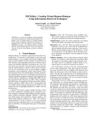
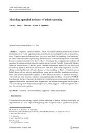
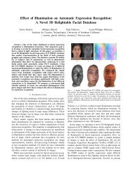
To appear in the ACM SIGGRAPH conference proceedings(a)(b)(a) perspective (b) projective (c) MCOP(c)Figure 6: Each viewpoint sees sections of multiple projector framesreflected by the spinning mirror to <strong>for</strong>m a single perspective image.The slices that compose the single view shown in (a) c<strong>an</strong> be seendirectly in high-speed video images taken of the mirror (b). (c)<strong>an</strong>d (d) show photographs of the mirror reflecting a sequence ofalternating all-black <strong>an</strong>d all-white frames from 56cm <strong>an</strong>d 300cmaway, respectively, showing that the number of frames seen varieswith viewer dist<strong>an</strong>ce.to where it intersects the surface of the mirror at point M. Uponintersecting the diffuser, we assume that this ray −−→ P ′ M spreads intoa vertical f<strong>an</strong> of light which intersects the circle of views V at V ′ .Seen from above, this intersection is easily calculated as a 2D linecircleintersection.We now know that projector pixel (u,v) reflects from mirror pointM toward viewpoint V ′ . Thus, the color it should display should bethe result of tracing a ray from V ′ toward point M. If our scene is alight field, we simply query ray V −−→ ′ M <strong>for</strong> the scene radi<strong>an</strong>ce at thatpoint. We discuss using this result to render 4D light fields in realtime in Section 6.4.3 DiscussionThe f<strong>an</strong>s of light from a given projector frame diverge horizontallytoward multiple viewpoints. As the mirror rotates, each viewpointaround the display sees a vertical line that sc<strong>an</strong>s out pixels fromnumerous projected MCOP images to <strong>for</strong>m a single perspective image.We captured the <strong>for</strong>mation of these slices using a high-speedcamera as seen in Figure 6(a,b). The number of slices that makeup <strong>an</strong> observed image depends on the viewpoint’s dist<strong>an</strong>ce fromthe display. We tested this by projecting a sequence of alternatingall-black <strong>an</strong>d all-white images, allowing the number of images contributingto <strong>an</strong>y one viewpoint to be counted easily. Closer to themirror (Figure 6(c)), the number of images that contributes to theview increases. As the viewpoint recedes (Figure 6(d)), the numberof images contributing to a view decreases to a minimum ofapproximately ten. This number never drops to one since our videoprojector is not orthographic.Comparison with other rendering methods Simpler techniquesc<strong>an</strong> be used to project imagery to the display, but they do not(d)Figure 7: A scene is rendered from above (top row) <strong>an</strong>d straight-on(bottom row) using three methods. (a) Projecting regular perspectiveimages exaggerates horizontal perspective <strong>an</strong>d causes stretchingwhen the viewpoint rises. (b) Projecting a perspective imagethat would appear correct to the viewer if the mirror were diffuseexaggerates horizontal perspective <strong>an</strong>d causes keystoning. (c)Our MCOP algorithm produces perspective-correct images <strong>for</strong> <strong>an</strong>yknown viewpoint height <strong>an</strong>d dist<strong>an</strong>ce.achieve correct perspective. [Cossairt et al. 2007] recommends displayingperspective or orthographic images of the scene directly tothe projector. Un<strong>for</strong>tunately, this technique yields images with exaggeratedhorizontal perspective (Figure 7(a)) since it does not considerthat the image seen at a viewpoint consists of vertical slices ofm<strong>an</strong>y of these perspective or orthographic images. This approachalso neglects projector ray divergence; the lower part of the spaceshipappears too tall since it is further from the projector.Another technique would be to project perspective images to thedisplay surface that would appear correct to a given viewpoint if themirror were replaced with a completely diffuse surface. [Dorseyet al. 1991; Raskar et al. 1998] describe this process in the contextof theater <strong>an</strong>d interactive applications. However, this techniquedoes not project perspective-correct imagery <strong>for</strong> our 3D display(Figure 7(b)). While the vertical perspective is accurate, the renderingshows exaggerated horizontal perspective (the wings splayoutward) <strong>an</strong>d the image is also skewed. Using the MCOP projectiontechnique described above, images appear perspective-correct<strong>for</strong> <strong>an</strong>y viewer on V, <strong>an</strong>d V c<strong>an</strong> be adjusted <strong>for</strong> <strong>an</strong>y estimated ortracked viewer height <strong>an</strong>d dist<strong>an</strong>ce (Figure 7(c)).5 Geometric CalibrationOur projection process requires knowing the intrinsic projector parameters<strong>an</strong>d its pose relative to the spinning mirror. We chooseour world coordinates to originate at the center of the mirror, withthe vertical axis (0,1,0) oriented along the mirror’s axis of rotation.Calibration is relatively straight<strong>for</strong>ward as we only use a single projector<strong>an</strong>d optical path with a single rotating element.We use the simple linear calibration approach outlined in Section3.2 of [Forsyth <strong>an</strong>d Ponce 2002]. The method requires at least 6correspondences between known 3D points <strong>an</strong>d their tr<strong>an</strong>s<strong>for</strong>med2D pixel positions. We ignore radial lens distortion as this wasmeasured to be insignific<strong>an</strong>t.5
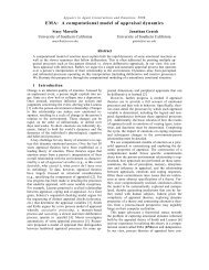
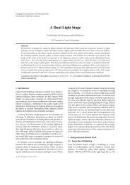
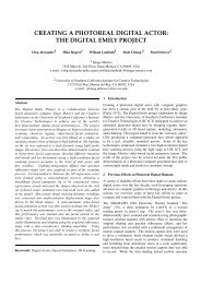
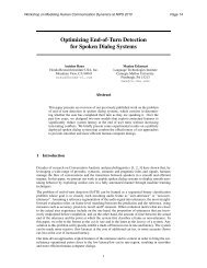
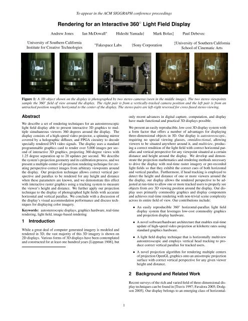
To appear in the ACM SIGGRAPH conference proceedings(a)(b)Figure 8: (a) Fiducial markers used <strong>for</strong> determining the projectionmatrix P. (b) The four outer mirror fiducials as seen by theprojector with the mirror at 0 ◦ <strong>an</strong>d 180 ◦ .We obtain known 3D positions by marking fixed points on the mirrorsurface. With the motor off, we position the mirror so that itfaces the front of the display <strong>an</strong>d attach a paper calibration targetconsisting of five fiducial markers on the mirror’s surface (Figure8). We project a centered crosshair pattern from the projector so thatit c<strong>an</strong> be positioned directly above the center fiducial. (The projectoris mounted so that its central projected pixel projects down vertically.)We use a mouse to move the crosshair to each of the otherfiducial markers, clicking the mouse to obtain the position of thecorresponding projector pixel. We then rotate the mirror 180 ◦ <strong>an</strong>dclick the four fiducials again, obtaining a total of eight 2D points.The eight fiducial positions <strong>for</strong>m a unit cube in space.6 Displaying Photographic <strong>Light</strong> <strong>Field</strong>sThis section describes how we capture, preprocess, <strong>an</strong>d dynamicallyrender 4D light fields to the device with correct horizontal <strong>an</strong>dvertical parallax leveraging the ray tracing projection developed inSection 4.2.<strong>Light</strong> <strong>Field</strong> Capture We begin by capturing a 4D light field ofa real object. In this work, we place the object on <strong>an</strong> inexpensivemotorized turntable (Figure 9, top row). A video camera is placedat a dist<strong>an</strong>ce of D = 1.0m in front of the object. The object is litwith ambient light <strong>an</strong>d/or lights attached to the turntable so that theobject <strong>an</strong>d its illumination remain in the same relationship to eachother during the rotation. We capture a movie sequence of at least288 frames of the object rotating <strong>360</strong> ◦ on the turntable, which takesa few seconds. We capture a full 4D light field by shooting multiplerotations of the turntable, raising the camera’s height H by 1.25cm<strong>for</strong> each successive rotation. We calibrate the intrinsic parameters<strong>for</strong> the camera <strong>an</strong>d record its pose <strong>for</strong> each rotation.Preprocessing the <strong>Light</strong> <strong>Field</strong> As discussed in Section 4, regularperspective images c<strong>an</strong> shown directly on the projector will notproduce correct perspective to viewers around the display. Thus,we pre-process the light field to produce images appropriate <strong>for</strong>projection. We first align our object <strong>an</strong>d display coordinate systemsby placing the origin at a point within the center of the objectdirectly above the center of the turntable, <strong>an</strong>d we align the y axis tothe turntable’s axis of rotation. Then, <strong>for</strong> each slice i of the capturedlight field taken from height H i , we generate a new, rebinned, lightfield slice as follows. We place the virtual viewing circle V aroundthe display at height H i <strong>an</strong>d dist<strong>an</strong>ce D. Then, <strong>for</strong> each of the 288mirror positions, we trace rays from the reflected projector at P ′through each pixel (u,v) to the mirror at M through to the viewpointV ′ on V <strong>an</strong>d then back toward M as described in Section 4.2.We then simply need to query the light field <strong>for</strong> its radi<strong>an</strong>ce alongFigure 9: (Top row) Two images from <strong>an</strong> object light field capturedusing a turntable. (Middle row) Resampled projector frames optimized<strong>for</strong> the same two viewer heights. Both frames compensate <strong>for</strong>the horizontal divergence of projector rays <strong>an</strong>d vertical stretchingat oblique viewing <strong>an</strong>gles. The images appear mirror-reversed (<strong>an</strong>d<strong>for</strong> most views, rotated) prior to projection. (Bottom row) A singlephotograph of the original object sitting to the right of its virtualversion shown on the 3D display.ray −−→ V ′ M. This is a simple query since we chose V to be coincidentwith the height <strong>an</strong>d dist<strong>an</strong>ce of the current slice of the light field: V ′thus lies on or between two of the same slice’s camera locations C i<strong>an</strong>d C i+1 as in Figure 5(c). To obtain the final pixel value, we onlyneed to bilinearly interpolate between the pixels from C i <strong>an</strong>d C i+1that look toward point M on the mirror.For our display, we next dither the rebinned slices using [Ostromoukhov2001] to create binary images as in the middle row ofFigure 9, <strong>an</strong>d we pack sets of 24 halftoned images into 24-bit colorimages. As there are 288 images in each rebinned slice, this yieldstwelve 24-bit color images per row. At 768 × 768 resolution, oneslice requires just over 20MB of texture memory, allowing a lightfield resolution of over 768 × 768 pixels by 288 × 32 views to bestored on a modern 768MB graphics card.By construction, each one of the rebinned light field slices yieldscorrect perspective when projected on the display <strong>an</strong>d observed<strong>an</strong>ywhere from the original slice’s height H i <strong>an</strong>d dist<strong>an</strong>ce D. If theviewer dist<strong>an</strong>ce remains near dist<strong>an</strong>ce D, one could produce accuratevertical parallax by swapping which slice is displayed accordingto the user’s height. To render the light field accurately <strong>for</strong> <strong>an</strong>yheight <strong>an</strong>d dist<strong>an</strong>ce, we use a dynamic rebinning process describedbelow.6
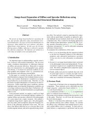
To appear in the ACM SIGGRAPH conference proceedingsProjector PEyePositionH i+2H i+1H iProjectorViewportMirrorViewpointsMirrorNormalQuad(H i)Quad(H i+1)Quad(H i+2)(a) (b) (c)Figure 10: (a) To produce correct vertical parallax, vertical light field rebinning is per<strong>for</strong>med dynamically by projecting the light field sliceclosest in <strong>an</strong>gle to the viewpoint onto each area of the mirror. (b) These projected areas define textured quadrilaterals on the mirror surface,each corresponding to a light field slice. (c) The areas corresponding to different original slices are made visible by inverting every otherquadrilateral of this dynamically rebinned projector frame.Figure 11: Photographs of eight frames from a 25-frame <strong>an</strong>imated light field as shown on the display.Dynamic Rebinning <strong>for</strong> Vertical Parallax We per<strong>for</strong>m dynamicvertical rebinning that samples from different preprocessed lightfield slices based on the viewer’s height h <strong>an</strong>d dist<strong>an</strong>ce d to producecorrect horizontal <strong>an</strong>d vertical perspective on the light field<strong>for</strong> <strong>an</strong>y viewpoint. For each mirror position, we consider each slicei’s nodal point at dist<strong>an</strong>ce D <strong>an</strong>d height H i in front of the mirror asshown in Figure 10(a). We project the midpoints between the slicesthrough the viewer position onto the mirror, <strong>an</strong>d then up into theprojector image. These projected midpoints <strong>for</strong>m <strong>an</strong> axis of pointscrossing the center of the projector image. We extend lines fromeach point perpendicularly to this axis, dividing the projector’s imageinto a set of regions, each one corresponding to the area <strong>for</strong>which light field slice i contains the rays that most closely correspondto the viewpoint’s view of the scene over that area. We delimitthe regions as quadrilaterals that extend wide enough to coverthe image as seen in Figure 10(b). Then, <strong>for</strong> each quadrilateral, werender a texture-mapped polygon that copies over the correspondingregion from each light field slice. A result of building up aprojected image from these different slices is seen in Figure 10(c).If the viewer is close to dist<strong>an</strong>ce D from the display, just one or twolight field slices will constitute the projected images. As the viewermoves <strong>for</strong>ward or back from D, the number of slices used will increase.Since the images on the graphics card are already dithered,we per<strong>for</strong>m no blending between the slices. However, our light fieldwas of sufficient vertical <strong>an</strong>gular resolution that the seams betweenthe slices were not noticeable. Figure 9, bottom row, shows a photographof a dynamically rebinned light field <strong>for</strong> a tracked camerawith the original object seen nearby in the frame, exhibiting consistentsize <strong>an</strong>d perspective. A sequence of dynamically-rebinned 4Dlight field imagery displayed to a moving camera is shown in theaccomp<strong>an</strong>ying video.Displaying <strong>an</strong> Animated <strong>Light</strong> <strong>Field</strong> Instead of using the graphicscard’s memory to store multiple vertical slices of <strong>an</strong> object’slight field, we c<strong>an</strong> store multiple temporal samples of a horizontalparallax-onlylight field. Figure 11 shows photographs from a 25-frame <strong>an</strong>imated light field of a running m<strong>an</strong> captured <strong>an</strong>d renderedusing the flowed reflect<strong>an</strong>ce field rendering technique of [Einarssonet al. 2006]. Alternatively, light fields from multi-camera systems[Y<strong>an</strong>g et al. 2002; Wilburn et al. 2005] could be used, or ahigh-speed single-camera system using a spinning mirror to varythe viewpoint as in [Jones et al. 2006a] could be used to capturesuch data.7 Visual Accommodation Per<strong>for</strong>m<strong>an</strong>ceAccommodation is the effect that each point of the displayed 3Dimage comes into focus at a depth that is consistent with its displayedbinocular disparity. Achieving correct visual accommodationc<strong>an</strong> signific<strong>an</strong>tly improve the visual effectiveness of a 3D display[Akeley et al. 2004]. We per<strong>for</strong>med a basic accommodationtest on our 3D display by photographing a test scene shown by thedisplay using a wide-aperture lens at different focal depths. Theresults of the experiment are shown in Figure 12.As we present a true light field in a horizontal pl<strong>an</strong>e, the accommodationof the hum<strong>an</strong> eye should be at the depth of features on thevirtual object. We have verified this to be true by placing a horizontalslit across the front of a long lens, <strong>an</strong>d then adjusting the focusfrom near to far on a model of small evenly spaced cubes whichfill the display’s volume. A detail of these images is presented inFigure 12(a) which shows receding boxes coming into focus as thelens is adjusted. The narrow depth-of-field of the lens naturallyblurs boxes <strong>for</strong>e <strong>an</strong>d aft of the focal dist<strong>an</strong>ce. It is interesting tonote that this blur is made of discrete images due to the qu<strong>an</strong>tizednature of our 288-image light field.7
To appear in the ACM SIGGRAPH conference proceedings(a) Horizontal focus ch<strong>an</strong>ge(b) Vertical focus ch<strong>an</strong>geFigure 12: (a) Correct horizontal accommodation Using a horizontalslit aperture, the front boxes come into focus when the camerafocus is near (top) <strong>an</strong>d the far boxes come into focus when thefocus is far (bottom). (b) Incorrect vertical accommodation Usinga vertical slit aperture, the camera focuses on the mirror pl<strong>an</strong>ethat slopes away from the viewer. The bottom boxes are in focuswhen the camera is focused near (left). The top boxes are in focuswhen the camera is focused far. An unoccluded observer wouldobserve <strong>an</strong> astigmatic combination of these two effects.Diffusion in the vertical pl<strong>an</strong>e disrupts the purity of the light field<strong>for</strong> <strong>an</strong>gles other th<strong>an</strong> that of direct reflection. This is confirmed inFigure 12(b) which was captured by adjusting focus from near tofar with a vertical slit placed in front of the long lens. We note thatthe focus recedes with the pl<strong>an</strong>e of the diffusing mirror, <strong>an</strong>d thatthe virtual depth of the small cubes does not play a role as it didwith the horizontal slit. The actual image is a blend of both, <strong>an</strong>dthe diffusing pl<strong>an</strong>e bisects the volume, which appears to provide acom<strong>for</strong>table field upon which to focus the eye.8 Displaying Color ImageryA straight<strong>for</strong>ward method to create a color version of our displaywould use a 3-chip DMD projector. In adv<strong>an</strong>ce of that, we haveimplemented a two-ch<strong>an</strong>nel field-sequential color system using atwo-sided tent-shaped diffusing mirror shown in Figure 13(a). Foreach side of the tent, we place a color filter between the holographicdiffusing film <strong>an</strong>d the first-surface mirror, which avoids introducingspecular first-surface reflections. We chose a Lee #131 cy<strong>an</strong> filter<strong>for</strong> one side <strong>an</strong>d a Lee #020 or<strong>an</strong>ge filter <strong>for</strong> the other, dividing thevisible spectrum approximately evenly into short <strong>an</strong>d long wavelengths.We convert RGB colors to Or<strong>an</strong>ge-Cy<strong>an</strong> colors by projectingthe linear RGB vector onto the pl<strong>an</strong>e sp<strong>an</strong>ned by the Or<strong>an</strong>ge<strong>an</strong>d Cy<strong>an</strong> colors.To render in color, we calibrate each pl<strong>an</strong>e of the tent mirror independentlyas in Section 5. Then, we render the 3D scene twice<strong>for</strong> each sub-frame, once <strong>for</strong> the or<strong>an</strong>ge side <strong>an</strong>d once <strong>for</strong> the cy<strong>an</strong>side, <strong>an</strong>d the calibration process ensures that each side is renderedtoward the appropriate set of viewpoints. The effect <strong>for</strong> the vieweris similar to the Kinemacolor 2-color cinema system, <strong>an</strong>d the choiceof filters allows <strong>for</strong> useful color reproduction <strong>for</strong> m<strong>an</strong>y scenes. Besidesachieving color, the tent-mirror system doubles the numberof images per second shown to the viewers, allowing a 40Hz fieldsequentialcolor frame rate which appears signific<strong>an</strong>tly more stableth<strong>an</strong> 20Hz monochrome.9 Future WorkThe work presented here suggests a number of avenues <strong>for</strong> furtherexploration. The rendering algorithms used here employ ditheredimages so using real time halftoning algorithms embedded in pixelshaders [Freundenberg et al. 2004] could allow better shading <strong>for</strong>interactive display content. We currently dither each projected imageindependently; we could improve the visual quality by also dif-(a)Figure 13: (a) A two-mirror tent <strong>for</strong> displaying two-toned colorimagery using or<strong>an</strong>ge <strong>an</strong>d cy<strong>an</strong> filters below the diffusers. (b) Aphotograph of color imagery displayed by our device.fusing the errors across projected <strong>an</strong>gle <strong>an</strong>d time.Naturally, it would be of interest to create correct vertical parallaxon the display without using the Polhemus tracking system. Onemethod to do this would be to place outward-looking stereo or depthcameras above the display to sense the positions of viewers aroundit, perhaps using infrared illumination to aid in sensing. If maderobust enough, the display could track <strong>an</strong>d render <strong>for</strong> a large numberof users as long as two users are not vertically aligned with eachother, which is relatively infrequent.To produce vertical parallax with no tracking whatsoever, it willbecome necessary to recreate the full 4D light field. This could beaccomplished by projecting onto a series of mirrors at mounted atdifferent <strong>an</strong>gles to provide a r<strong>an</strong>ge of vertical parallax in a m<strong>an</strong>nerrelated to that of [Otsuka et al. 2006], in which horizontal parallaxwas created at the expense of resolution. Other configurations ofthe mirrored surface where diffusion characteristics vary across thesurface may also enable vertical parallax. We would also like toexplore obtaining vertical parallax through multiple projectors asthis would also share the rendering load across more th<strong>an</strong> one set ofgraphics hardware.An unexplored feature of the display is its ability to show differentversions of the scene depending on the direction of view. Whenmultiple people use the display, the imagery could be tailored toeach user. Users could all view a common 3D scene with correctperspective, such as a 3D map, yet each tracked user couldsee front-facing <strong>an</strong>notations in their native l<strong>an</strong>guage.Additional computational illumination applications could resultfrom considering our system not as a 3D display device but as acontrollable light field generator. The system could potentially beuseful <strong>for</strong> near-field reflectometry, or <strong>for</strong> the creation of a large virtualdisplay area by reflecting the diverging light from the displaythrough reflecting mirrors, such as a tapered Kaleidoscope configuration[H<strong>an</strong> <strong>an</strong>d Perlin 2003].10 ConclusionThe display we present in this work is able to show modest-sized(13cm) scenes in 3D to <strong>an</strong>y number of people gathered around toview its imagery. The display shows correct occlusion effects, <strong>an</strong>dits <strong>an</strong>gular resolution is sufficient so that the tr<strong>an</strong>sitions between thevertical zones are essentially unnoticeable. Our high-speed renderingtechniques allow the display of scenes that are fully interactive,<strong>an</strong>d c<strong>an</strong> be <strong>an</strong>imated <strong>an</strong>d m<strong>an</strong>ipulated on the fly with a st<strong>an</strong>dardPC <strong>an</strong>d programmable graphics card. The novel multiple-center-ofprojectionrendering technique allows the display to exhibit correctgeometric perspective <strong>an</strong>d parallax <strong>for</strong> <strong>an</strong>y number of viewers solong as their heights <strong>an</strong>d dist<strong>an</strong>ces are known or c<strong>an</strong> be estimated.We described the projection mathematics both <strong>for</strong> geometric 3Dmodels <strong>an</strong>d photographically acquired light fields.(b)8
To appear in the ACM SIGGRAPH conference proceedingsOur hope is that our contributions will enable other researchers incomputer graphics <strong>an</strong>d immersive displays to develop new 3D technology<strong>an</strong>d content. 3D displays such as ours should become increasinglypractical in the years to come as the core graphics <strong>an</strong>dimage projection components decrease in price <strong>an</strong>d increase in capability.AcknowledgementsThe authors wish to th<strong>an</strong>k Naho Inamoto <strong>an</strong>d Bruce Lamond<strong>for</strong> capturing <strong>an</strong>d processing the object light fields, Charles-FelixChabert <strong>for</strong> rendering the <strong>an</strong>imated light field, Pieter Peers <strong>an</strong>dTim Hawkins <strong>for</strong> valuable suggestions <strong>an</strong>d proofreading, Bri<strong>an</strong>Miller <strong>an</strong>d Bruce Lamond <strong>for</strong> video editing, Jacki Morie <strong>an</strong>d Se<strong>an</strong>Bouchard <strong>for</strong> lending their tracking system, <strong>an</strong>d Dell Lunce<strong>for</strong>d,Tom Pereira, Jeff Fisher, Bill Swartout, R<strong>an</strong>dy Hill, <strong>an</strong>d R<strong>an</strong>dolphHall <strong>for</strong> their support <strong>an</strong>d assist<strong>an</strong>ce with this work. This workwas sponsored by the U.S. Army Research, Development, <strong>an</strong>d EngineeringComm<strong>an</strong>d (RDECOM) <strong>an</strong>d the University of SouthernCali<strong>for</strong>nia Office of the Provost. The high-speed projector was originallydeveloped by a gr<strong>an</strong>t from the Office of Naval Research underthe guid<strong>an</strong>ce of Ralph Wachter <strong>an</strong>d Larry Rosenblum. The contentof the in<strong>for</strong>mation does not necessarily reflect the position or thepolicy of the US Government, <strong>an</strong>d no official endorsement shouldbe inferred.ReferencesAGOCS, T., BALOGH, T., FORGACS, T., BETTIO, F., GOBBETTI,E., ZANETTI, G., AND BOUVIER, E. 2006. A large scale interactiveholographic display. In VR ’06: Proceedings of the IEEEVirtual Reality Conference (VR 2006), IEEE Computer Society,Washington, DC, USA, 57.AKELEY, K., WATT, S. J., GIRSHICK, A. R., AND BANKS, M. S.2004. A stereo display prototype with multiple focal dist<strong>an</strong>ces.ACM Tr<strong>an</strong>sactions on <strong>Graphics</strong> 23, 3 (Aug.), 804–813.BALOGH, T., DOBRANYI, Z., FORGACS, T., MOLNAR, A.,SZLOBODA, L., GOBBETTI, E., MARTON, F., BETTIO, F.,PINTORE, G., ZANETTI, G., BOUVIER, E., AND KLEIN, R.2006. An interactive multi-user holographic environment. InSIGGRAPH ’06: ACM SIGGRAPH 2006 Emerging technologies,ACM Press, New York, NY, USA, 18.BATCHKO, R. G. 1994. Three-hundred-sixty degree electroholographicstereogram <strong>an</strong>d volumetric display system. In Proc.SPIE, vol. 2176, 30–41.CHAI, J.-X., TONG, X., CHAN, S.-C., AND SHUM, H.-Y. 2000.Plenoptic sampling. In Proceedings of ACM SIGGRAPH 2000,Computer <strong>Graphics</strong> Proceedings, Annual Conference Series,307–318.COSSAIRT, O. S., AND NAPOLI, J., 2005. Radial multiview3-dimensional displays. United States Patent Application2005/0180007, Aug.COSSAIRT, O., TRAVIS, A. R., MOLLER, C., AND BENTON,S. A. 2004. Novel view sequential display based on dmd technology.In Proc. SPIE, Stereoscopic Displays <strong>an</strong>d Virtual RealitySystems XI, A. J. Woods, J. O. Merritt, S. A. Benton, <strong>an</strong>d M. T.Bolas, Eds., vol. 5291, 273–278.COSSAIRT, O. S., NAPOLI, J., HILL, S. L., DORVAL, R. K., ANDFAVALORA, G. E. 2007. Occlusion-capable multiview volumetricthree-dimensional display. Applied Optics 46, 8 (Mar),1244–1250.DODGSON, N. A. 2005. Autostereoscopic 3D displays. Computer38, 8, 31–36.DORSEY, J. O., SILLION, F. X., AND GREENBERG, D. P. 1991.Design <strong>an</strong>d simulation of opera lighting <strong>an</strong>d projection effects.In SIGGRAPH ’91: Proceedings of the 18th <strong>an</strong>nual conferenceon Computer graphics <strong>an</strong>d interactive techniques, ACM Press,New York, NY, USA, 41–50.EINARSSON, P., CHABERT, C.-F., JONES, A., MA, W.-C., LA-MOND, B., HAWKINS, T., BOLAS, M., SYLWAN, S., AND DE-BEVEC, P. 2006. Relighting hum<strong>an</strong> locomotion with flowedreflect<strong>an</strong>ce fields. In <strong>Rendering</strong> Techniques 2006: 17th EurographicsSymposium on <strong>Rendering</strong>, 183–194.ENDO, T., KAJIKI, Y., HONDA, T., AND SATO, M. 2000. Cylindrical3D video display observable from all directions. In 8th PacificConference on Computer <strong>Graphics</strong> <strong>an</strong>d Applications, 300–306.FAVALORA, G. E. 2005. Volumetric 3D displays <strong>an</strong>d applicationinfrastructure. Computer 38, 8, 37–44.FORSYTH, D. A., AND PONCE, J. 2002. Computer Vision: AModern Approach. Prentice Hall, ch. 3, 45.FREUNDENBERG, B., MASUCH, M., AND STROTHOTTE, T.2004. Game Programming Gems 4. Thomson/Delmar Learning,ch. Real-Time Halftoning: Fast <strong>an</strong>d Simple Stylized Shading,443–449.GORTLER, S. J., GRZESZCZUK, R., SZELISKI, R., AND COHEN,M. F. 1996. The lumigraph. In Proceedings of SIGGRAPH96, Computer <strong>Graphics</strong> Proceedings, Annual Conference Series,43–54.HALLE, M. W., BENTON, S. A., KLUG, M. A., AND UNDER-KOFFLER, J. S. 1991. The ultragram: A generalized holographicstereogram. In Proceedings of the SPIE Practical Holography V.HAN, J. Y., AND PERLIN, K. 2003. Measuring bidirectionaltexture reflect<strong>an</strong>ce with a kaleidoscope. ACM Tr<strong>an</strong>sactions on<strong>Graphics</strong> 22, 3 (July), 741–748.HOU, X., WEI, L.-Y., SHUM, H.-Y., AND GUO, B. 2006. Realtimemulti-perspective rendering on graphics hardware. In <strong>Rendering</strong>Techniques 2006: 17th Eurographics Workshop on <strong>Rendering</strong>,93–102.ISAKSEN, A., MCMILLAN, L., AND GORTLER, S. J. 2000.Dynamically reparameterized light fields. In Proceedings ofACM SIGGRAPH 2000, Computer <strong>Graphics</strong> Proceedings, AnnualConference Series, 297–306.JONES, A., DEBEVEC, P., BOLAS, M., AND MCDOWALL, I.2006. Concave surround optics <strong>for</strong> rapid multiview imaging. InProceedings of the 25th Army Science Conference.JONES, A., GARDNER, A., BOLAS, M., MCDOWALL, I., ANDDEBEVEC, P. 2006. Per<strong>for</strong>m<strong>an</strong>ce geometry capture <strong>for</strong> spatiallyvarying relighting. In 3rd Europe<strong>an</strong> Conference on Visual MediaProduction (CVMP 2006), 127–133.KAJIYA, J. T., AND KAY, T. L. 1989. <strong>Rendering</strong> fur with threedimensional textures. In SIGGRAPH ’89: Proceedings of the16th <strong>an</strong>nual conference on Computer graphics <strong>an</strong>d interactivetechniques, ACM Press, New York, NY, USA, 271–280.LEVOY, M., AND HANRAHAN, P. M. 1996. <strong>Light</strong> field rendering.In Proceedings of ACM SIGGRAPH 96, Computer <strong>Graphics</strong> Proceedings,Annual Conference Series, 31–42.LIPPMAN, G. 1908. Epreuves reversibles donn<strong>an</strong>t la sensation durelief. Journal of Physics 7, 4 (Nov), 821–835.9
To appear in the ACM SIGGRAPH conference proceedingsMAEDA, H., HIROSE, K., YAMASHITA, J., HIROTA, K., ANDHIROSE, M. 2003. All-around display <strong>for</strong> video avatar in realworld. In ISMAR ’03: Proceedings of the The 2nd IEEE <strong>an</strong>dACM International Symposium on Mixed <strong>an</strong>d Augmented Reality,IEEE Computer Society, Washington, DC, USA, 288.MATUSIK, W., AND PFISTER, H. 2004. 3D tv: a scalable system<strong>for</strong> real-time acquisition, tr<strong>an</strong>smission, <strong>an</strong>d autostereoscopic displayof dynamic scenes. ACM Tr<strong>an</strong>sactions on <strong>Graphics</strong> 23, 3(Aug.), 814–824.MCDOWALL, I., AND BOLAS, M. 2005. Display, sensing, <strong>an</strong>dcontrol applications <strong>for</strong> digital micromirror displays. In IEEEVR 2005 - Emerging Display Technologies, 35–36.MILLER, J. R. 1987. Geometric approaches to nonpl<strong>an</strong>ar quadricsurface intersection curves. ACM Tr<strong>an</strong>sactions on <strong>Graphics</strong> 6, 4(Oct.), 274–307.OSTROMOUKHOV, V. 2001. A simple <strong>an</strong>d efficient error-diffusionalgorithm. In Proceedings of ACM SIGGRAPH 2001, Computer<strong>Graphics</strong> Proceedings, Annual Conference Series, 567–572.OTSUKA, R., HOSHINO, T., AND HORRY, Y. 2006. Tr<strong>an</strong>spost: Anovel approach to the display <strong>an</strong>d tr<strong>an</strong>smission of <strong>360</strong> degreesviewable3D solid images. IEEE Tr<strong>an</strong>sactions on Visualization<strong>an</strong>d Computer <strong>Graphics</strong> 12, 2, 178–185.POULIN, P., AND FOURNIER, A. 1990. A model <strong>for</strong> <strong>an</strong>isotropicreflection. 273–282.RASKAR, R., WELCH, G., CUTTS, M., LAKE, A., STESIN, L.,AND FUCHS, H. 1998. The office of the future: A unifiedapproach to image-based modeling <strong>an</strong>d spatially immersive displays.In Proceedings of SIGGRAPH 98, Computer <strong>Graphics</strong>Proceedings, Annual Conference Series, 179–188.SULLIVAN, A. 2003. A solid-state multi-pl<strong>an</strong>ar volumetric display.SID Symposium Digest of. Technical Papers 32, 1 (May), 1531–1533.TANAKA, K., AND AOKI, S. 2006. A method <strong>for</strong> the real-timeconstruction of a full parallax light field. In Stereoscopic Displays<strong>an</strong>d Virtual Reality Systems XIII. Proceedings of the SPIE,Volume 6055, pp. 397-407 (2006)., A. J. Woods, N. A. Dodgson,J. O. Merritt, M. T. Bolas, <strong>an</strong>d I. E. McDowall, Eds., 397–407.TRAVIS, A. R. L. 1997. The display of three-dimensional videoimages. Proceedings of the IEEE 85, 11 (Nov), 1817–1832.WILBURN, B., JOSHI, N., VAISH, V., TALVALA, E.-V., AN-TUNEZ, E., BARTH, A., ADAMS, A., HOROWITZ, M., ANDLEVOY, M. 2005. High per<strong>for</strong>m<strong>an</strong>ce imaging using large cameraarrays. ACM Tr<strong>an</strong>sactions on <strong>Graphics</strong> 24, 3 (Aug), 765–776.YANG, J. C., EVERETT, M., BUEHLER, C., AND MCMILLAN, L.2002. A real-time distributed light field camera. In <strong>Rendering</strong>Techniques 2002: 13th Eurographics Workshop on <strong>Rendering</strong>,77–86.YENDO, T., KAWAKAMI, N., AND TACHI, S. 2005. Seelinder:the cylindrical lightfield display. In SIGGRAPH ’05: ACM SIG-GRAPH 2005 Emerging technologies, ACM Press, New York,NY, USA, 16.ZWICKER, M., MATUSIK, W., DURAND, F., AND PFISTER, H.2006. Antialiasing <strong>for</strong> automultiscopic 3D displays. In <strong>Rendering</strong>Techniques 2006: 17th Eurographics Workshop on <strong>Rendering</strong>,73–82.AApproximating Conical ReflectionsThe projection algorithm presented in Section 4 makes a slight approximationby assuming that the mirror diffuses light from a rayof the projector into a f<strong>an</strong> of light within a vertical pl<strong>an</strong>e. However,these f<strong>an</strong>s of light are generally conical in shape. The reflect<strong>an</strong>ceproperties of <strong>an</strong> <strong>an</strong>isotropic surface c<strong>an</strong> be simulated assmall parallel cylindrical micro-facets aligned with domin<strong>an</strong>t axisof <strong>an</strong>isotropy ⃗a [Poulin <strong>an</strong>d Fournier 1990]. In our setup, ⃗a is a horizontalvector in the pl<strong>an</strong>e of the mirror. A projector ray striking acylindrical micro-facet will be specularly reflected at a mirror <strong>an</strong>glealong the cylinder t<strong>an</strong>gent. The reflected light <strong>for</strong>ms a cone whose<strong>an</strong>gle at the apex is equal to the <strong>an</strong>gle of incidence [Kajiya <strong>an</strong>d Kay1989]. The reflected light <strong>for</strong>ms a pl<strong>an</strong>e in the special case wherethe incident light is perpendicular to the domin<strong>an</strong>t <strong>an</strong>isotropic axis.As our projector is mounted vertically relative to the mirror witha relatively narrow field of view, the projector rays always hit themirror at close to 90 degrees yielding extremely wide cones. Furthermore,the cones are t<strong>an</strong>gent to the ideal vertical pl<strong>an</strong>e in thevicinity of rays −→ P ′ Q, making these pl<strong>an</strong>es close approximations tothe reflect f<strong>an</strong>s of light in our setup. The step that involves reflectingthe projector through the pl<strong>an</strong>e of the mirror also implicitly makesthis assumption, but again the effects are minimal with our configuration.Errors would appear as a narrowing of the horizontalperspective at extremely high <strong>an</strong>d low viewpoints. Analytically intersectinga cone with the viewing circle V is possible but computationallyexpensive, requiring solving a higher-order polynomialequation [Miller 1987]. In practice, a look-up table could be employedto correct <strong>for</strong> the small projection errors introduced by theconical reflection.BVertex Shader CodeThe following CG shader code projects a 3D scene vertex into projectorcoordinates as described in Section 4.1. It assumes helperfunctions are defined <strong>for</strong> basic geometric intersection operations.void rasterVS(float4 Q : POSITION, // vertex positionfloat4 Qcol : COLOR0, // vertex coloruni<strong>for</strong>m float4x4 ModelViewProj, // projector tr<strong>an</strong>s<strong>for</strong>muni<strong>for</strong>m float4 P, // reflected projector position P’uni<strong>for</strong>m float d,// view radiusuni<strong>for</strong>m float h,// view heightuni<strong>for</strong>m float4 mirror_norm, // normal of mirror pl<strong>an</strong>eout float4 oQ : POSITION,out float4 oQcol : COLOR0 ){// define ray from reflected projector position P’ to vertex Qfloat4 PQ = Q - P;PQ = normalize(PQ);}// compute intersection of ray PQ with vertical cylinder with// radius d to find view position V’V = RayCylinderIntersection(PQ, d);V.y = h; // set correct viewer height// define ray from ideal viewing position V’ to vertex Qfloat4 VQ = Q - V;VQ = normalize(VQ);// compute intersection ray VQ with mirror pl<strong>an</strong>e to find point Mfloat4 M = RayPl<strong>an</strong>eIntersection(VQ, mirror_norm);oQ = mul( ModelViewProj, M ); // project M into projectoroQcol = Qcol;// keep the existing vertex color// recompute depth in based on dist<strong>an</strong>ce from V’oQ.z = length(V - Q) / (2 * length(V - M));10