Fibre Optic Connectors 5
Fibre Optic Connectors 5
Fibre Optic Connectors 5

You also want an ePaper? Increase the reach of your titles
YUMPU automatically turns print PDFs into web optimized ePapers that Google loves.
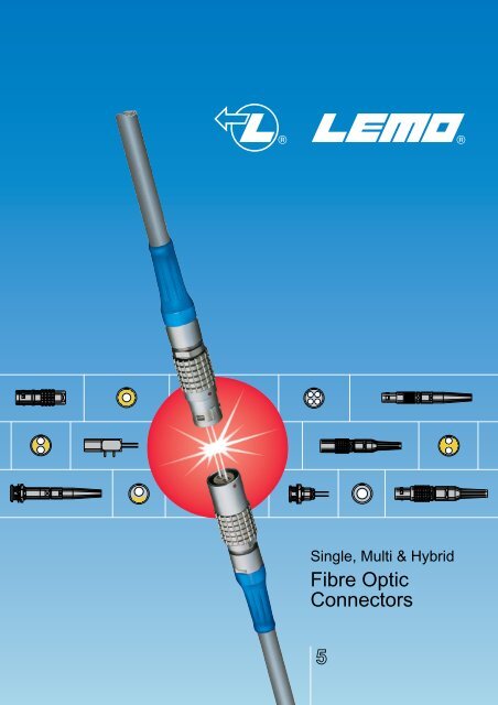
Single, Multi & Hybrid<br />
<strong>Fibre</strong> <strong>Optic</strong><br />
<strong>Connectors</strong><br />
5
Dear Customers,<br />
As far as data transmission is concerned, the superior characteristics of fibre optics compared to electrical<br />
cables are clearly recognised today.<br />
The advantages of fibre optics include a transmission capacity 10 times greater than that of conventional<br />
coaxial cables, in only one tenth of the size. The reduced weight and space requirements make handling<br />
and line installation much easier. Furthermore, fibre optics is characterized by low signal amplitude loss,<br />
no susceptibility to electromagnetic interference, and an absence of interference between neighbouring<br />
lines. It also offers greater security due to the difficulty of intercepting optical signals.<br />
The growing number of applications is more and more varied, and the annual growth rate of fibre optics<br />
is greater than 10%. Current applications of fibre optics include: telemetry, process control, data transmission,<br />
cable and closed circuit television, as well as laser signal transmission in medical applications.<br />
However, most systems equipped with fibre optics also require simultaneous electrical energy for control<br />
operations and power supply. Current practice involves the use of separate electrical and fibre optic<br />
connectors.<br />
The new technology developed by LEMO greatly simplifies this practice by combining electrical and fibre<br />
optic signals in a single connector.<br />
LEMO can now offer you a full range of mixed electrical/fibre optic connectors for singlemode or multimode<br />
transmission. This product range is available with metal or plastic outer shells, as well as in a watertight<br />
version.<br />
The range is completed by the addition of a single channel fibre optic connector series. All LEMO fibre<br />
optic connectors use a plug and socket push-pull self-latching connection system, obviating the need<br />
for plug to plug adaptors. This is a major advantage of the LEMO technology over its competitors.<br />
With the aim of providing the best possible answers to your fibre optic needs, LEMO has established an<br />
important research and development facility to provide quick and effective solutions to your design requirements.<br />
LEMO ISO 9001 certified has been improving its “quality culture” with the aim of reaching TQM. Offering<br />
zero defect products with due regard to the environment and meeting delivery requirements, are LEMO’s<br />
two main concerns.<br />
Certified Quality System<br />
LEMO SA<br />
General Management<br />
ISO<br />
9001<br />
Reg. No. 10472 - 03<br />
No reproduction or use without express permission of editorial or pictorial content, in any manner.<br />
Printed in Switzerland, April 2002 © LEMO SA<br />
LEMO reserve the right at all times to modify and improve specifications without any notification. Pdf updated, March 2011
® ®<br />
General Characteristics......................<br />
00 Series ....................................................<br />
0B Series....................................................<br />
0K Series....................................................<br />
2B to 5B Series .......................................<br />
2K to 5K Series .......................................<br />
Table of Contents<br />
General Production Programme .................................................................................................page 3<br />
Main Characteristics and Types .............................................................................................................3<br />
Series and Types......................................................................................................................................4<br />
LEMO’s Push-Pull Self-Latching Connection System..........................................................................5<br />
<strong>Fibre</strong> <strong>Optic</strong> <strong>Connectors</strong> Production Programme ..................................................................................6<br />
Introduction ..............................................................................................................................................7<br />
Selection of the LEMO <strong>Fibre</strong> <strong>Optic</strong> Contacts, Series and Contact Configurations.....................................8<br />
Acceptable Cable Diameter .......................................................................................................................9<br />
Selection of Electrical Contact Types.........................................................................................................9<br />
Part Numbering System ...........................................................................................................................10<br />
Interconnections.......................................................................................................................................13<br />
Model Description ....................................................................................................................................13<br />
Part Section Showing Internal Components ................................................................................................14<br />
Technical Characteristics ..........................................................................................................................14<br />
Alignment Key and Polarized Keying Systems ........................................................................................14<br />
Part Number Example..............................................................................................................................15<br />
Models - Series ........................................................................................................................................16<br />
<strong>Fibre</strong> Type ................................................................................................................................................17<br />
Housing, Cable Fixing Type, Bend Relief, Tooling, Panel Cut-Outs ........................................................18<br />
Interconnections.......................................................................................................................................21<br />
Model Description ....................................................................................................................................21<br />
Part Section Showing Internal Components ................................................................................................22<br />
Technical Characteristics ..........................................................................................................................22<br />
Alignment Key and Polarized Keying Systems ........................................................................................22<br />
Part Number Example..............................................................................................................................23<br />
Models - Series ........................................................................................................................................24<br />
<strong>Fibre</strong> Type, Housing.................................................................................................................................25<br />
Bend Relief, Tooling, Panel Cut-Outs ......................................................................................................26<br />
Interconnections.......................................................................................................................................29<br />
Model Description ....................................................................................................................................29<br />
Part Section Showing Internal Components ................................................................................................30<br />
Technical Characteristics ..........................................................................................................................30<br />
Alignment Key and Polarized Keying Systems ........................................................................................30<br />
Part Number Example..............................................................................................................................31<br />
Models - Series ........................................................................................................................................32<br />
<strong>Fibre</strong> Type ................................................................................................................................................32<br />
Housing, Bend Relief, Tooling, Panel Cut-Outs .......................................................................................33<br />
Interconnections.......................................................................................................................................37<br />
Model Description ....................................................................................................................................37<br />
Part Section Showing Internal Components ................................................................................................38<br />
Technical Characteristics ..........................................................................................................................38<br />
Alignment Key and Polarized Keying Systems ........................................................................................38<br />
Part Number Example..............................................................................................................................39<br />
Models - Series ........................................................................................................................................40<br />
Tooling, Panel Cut-Outs...........................................................................................................................45<br />
Interconnections.......................................................................................................................................47<br />
Model Description ....................................................................................................................................47<br />
Part Section Showing Internal Components ................................................................................................48<br />
Technical Characteristics ..........................................................................................................................48<br />
Alignment Key and Polarized Keying Systems ........................................................................................48<br />
Part Number Example..............................................................................................................................49<br />
Models - Series ........................................................................................................................................50<br />
Tooling, Panel Cut-Outs...........................................................................................................................53<br />
Types (2B-5B and 2K-5K series) ..........................................................................................................55<br />
Housing, Electrical Contact (2B-5B and 2K-5K series).........................................................................58<br />
Collets (2B-5B and 2K-5K series).........................................................................................................59<br />
Variant (2B-5B and 2K-5K series).........................................................................................................61<br />
1
® ®<br />
Table of Contents<br />
3K.93C Series ..........................................<br />
F1 <strong>Fibre</strong> <strong>Optic</strong> Contact........................<br />
F2 <strong>Fibre</strong> <strong>Optic</strong> Contact........................<br />
Accessories..............................................<br />
Tooling........................................................<br />
Interconnections.......................................................................................................................................65<br />
Model Description ....................................................................................................................................65<br />
Part Section Showing Internal Components ................................................................................................66<br />
Technical Characteristics ..........................................................................................................................66<br />
Alignment Key and Polarized Keying Systems ........................................................................................67<br />
Part Number Example..............................................................................................................................67<br />
Models - Series ........................................................................................................................................68<br />
Types .......................................................................................................................................................71<br />
<strong>Fibre</strong> <strong>Optic</strong> Contact, Accessories.............................................................................................................72<br />
Tooling .....................................................................................................................................................74<br />
<strong>Fibre</strong> <strong>Optic</strong> Tooling, Crimping Tools for Electrical Contacts.....................................................................75<br />
Termination Instruction, Panel Cut-Outs ..................................................................................................76<br />
Introduction, Part Section Showing Internal Components........................................................................77<br />
Technical Characteristics, Part Number Example....................................................................................77<br />
Model - FO Contact Type, <strong>Fibre</strong> Type......................................................................................................78<br />
Introduction, Part Section Showing Internal Components, Technical Characteristics .............................79<br />
Part Number Example, Model - FO Contact Type, <strong>Fibre</strong> Type ................................................................80<br />
Cable Fixing Type, Accessory..................................................................................................................81<br />
Insertion and Extraction of the <strong>Fibre</strong> <strong>Optic</strong> Contacts................................................................................82<br />
Insulators, Crimp Electrical Contacts .......................................................................................................85<br />
Caps.........................................................................................................................................................86<br />
Bend Reliefs.............................................................................................................................................91<br />
Insulating Washers, Double Panel Washers............................................................................................93<br />
Locking Washers, Tapered Washers, Hexagonal Nuts ...........................................................................94<br />
Notched Nuts, Conical Nuts, Round Nuts ................................................................................................95<br />
Earthing Washers.....................................................................................................................................96<br />
Spanners..................................................................................................................................................97<br />
Pliers, Taps ..............................................................................................................................................99<br />
Crimping Tools for Electrical Contacts, Positioners, Turrets..................................................................100<br />
Extraction Tools, Retention Testing Tools .............................................................................................101<br />
Tools for type C Coaxial Contacts<br />
Crimping Tool, Dies, Extractors..............................................................................................................102<br />
<strong>Fibre</strong> <strong>Optic</strong> Tooling...............................<br />
Technical Characteristics..................<br />
Complete Workstation............................................................................................................................103<br />
Crimping Tool, Epoxy Curing Jig, Epoxy Curing Oven, Polishing Tool..................................................104<br />
<strong>Fibre</strong> Inspection Microscope, Microscope Adaptor, Extractor................................................................105<br />
F2 Contact Alignment Device, F4 Contact Alignment Device ................................................................105<br />
Cleaning Tool, Cleaning Kit....................................................................................................................106<br />
Outer shell..............................................................................................................................................107<br />
Insulator .................................................................................................................................................108<br />
<strong>Fibre</strong> <strong>Optic</strong> Contacts ..............................................................................................................................109<br />
Electrical Contact ...................................................................................................................................112<br />
Cable Fixing ...........................................................................................................................................115<br />
Preferred <strong>Fibre</strong> <strong>Optic</strong> Cable Types ........................................................................................................118<br />
2
® ®<br />
General Production Program<br />
<strong>Connectors</strong><br />
Patch Panels<br />
Unipole from 2 to 150 Amps<br />
Coaxial 50 and 75 Ω<br />
Coaxial 50 Ω (NIM-CAMAC)<br />
Coaxial 50 Ω for frequency → 12 GHz<br />
Multicoaxial 50 and 75 Ω<br />
Multipole from 2 to 106 contacts<br />
High Voltage 3, 5, 8, 10, 15, 30 and 50 kV cc<br />
Multi High Voltage 3, 5, and 10 kV cc<br />
Triaxial 50 and 75 Ω<br />
Quadrax<br />
Mixed: High Voltage (LV) + Low Voltage (LV)<br />
Mixed: Coax + LV<br />
Mixed: Triax + LV<br />
Thermocouple<br />
Multithermocouple<br />
● <strong>Fibre</strong> optic single-mode<br />
● <strong>Fibre</strong> optic multi-mode<br />
● Mixed: fibre optic + LV<br />
Mixed: fibre optic + coax + LV<br />
Fluidic<br />
Multifluidic<br />
Mixed: fluidic + LV<br />
Subminiature<br />
Miniature<br />
Printed circuit board<br />
Remote handling<br />
Watertight<br />
Sealed (pressure and/or vacuum)<br />
● With plastic outer shell<br />
● With aluminium outer shell<br />
● With stainless steel outer shell<br />
With special radiation resistant insulator material<br />
With screw thread coupling for very high pressure<br />
With microswitch<br />
For audio-mono applications: triax<br />
For audio-mono applications: 3 contacts<br />
For audio-stereo applications: quadrax<br />
For audio-stereo applications: 6 contacts<br />
For video applications: coax 75 Ω<br />
Patch Panels<br />
Adaptors<br />
Accessories<br />
Tooling<br />
For video HDTV applications: 3 coax 75 Ω + 2LV<br />
For fibre optic applications<br />
For BNC, C, UHF, N, CINCH, GEN-RADIO connectors<br />
For TNC, SMA connectors<br />
● Insulator for crimp contacts<br />
● Crimp contacts<br />
Coaxial contacts<br />
Triaxial contacts<br />
● <strong>Fibre</strong> optic contacts<br />
● <strong>Fibre</strong> optic ferrules<br />
● Caps and bend reliefs<br />
● Insulating washers<br />
● Double plastic panel washers<br />
● Locking washers<br />
● Tapered washers<br />
● Hexagonal nuts<br />
● Conical nuts<br />
● Round nuts<br />
● Notched nuts<br />
● Earthing washers<br />
Lead-through with cable collet<br />
● Spanners<br />
● Spanners for assembling plug<br />
● Assembly tool<br />
● Pliers<br />
● Tap<br />
● Crimping tools<br />
● Positioners<br />
● Crimping dies<br />
● Extractors<br />
● Insertion testing tool for crimp contacts<br />
● <strong>Fibre</strong> optic termination workstation<br />
● <strong>Fibre</strong> optic polishing tools<br />
On request Filtered connectors<br />
● <strong>Connectors</strong> with special alloy housing<br />
Mixed special connectors<br />
● Assembly onto cable<br />
● <strong>Connectors</strong>, accessories and tools found in this catalogue.<br />
Main Characteristics and Types<br />
Series<br />
STANDARD<br />
WATERTIGHT<br />
KEYED<br />
KEYED<br />
WATERTIGHT<br />
SCREW<br />
01 (Minax)<br />
00 (NIM-CAMAC)<br />
00 (unipole)<br />
05 / R0<br />
0S to 6S<br />
0A / 4A<br />
1D / 2C<br />
1Y-3Y-6Y<br />
0E to 6E<br />
3T<br />
4M<br />
00 (multipole)<br />
0B to 5B<br />
2G/5G<br />
0K to 5K<br />
0F to 5F<br />
2N to 5N<br />
03<br />
0V to 5V<br />
0W to 5W<br />
2U to 5U<br />
Latching<br />
Push-Pull<br />
Screw<br />
Key<br />
Stepped insulator (Half-Moon)<br />
Key (G) or other key-way code<br />
Key (G) or stepped<br />
insulator (Half-Moon)<br />
Shell<br />
Metal or plastic Metal Metal or plastic Metal<br />
Metal<br />
Insulator<br />
Hermaphroditic or cylindrical<br />
Cylindrical<br />
Hermaphroditic<br />
or cylindrical<br />
Contact<br />
Solder or print<br />
Solder, crimp or print<br />
Solder<br />
(crimp or print)<br />
3
® ®<br />
Series and Types<br />
Types<br />
Series<br />
Unipole<br />
Coaxial 50 Ω<br />
Coaxial 75 Ω<br />
Multipole<br />
High Voltage<br />
Triaxial 50 Ω<br />
Triaxial 75 Ω<br />
Quadrax<br />
Multi HV<br />
Multi Coaxial<br />
Mixed HV+LV<br />
Mixed Coax+LV<br />
Mixed Triax+LV<br />
<strong>Fibre</strong> <strong>Optic</strong><br />
Multi FO<br />
Mixed FO+LV+…<br />
Fluidic<br />
Multi fluidic<br />
Mixed fluidic+LV<br />
Thermocouple<br />
Standard<br />
Watertight<br />
Keyed<br />
Keyed<br />
watertight<br />
Screw<br />
01<br />
00<br />
05<br />
R0<br />
0A<br />
0S<br />
1S<br />
2S<br />
3S<br />
4S<br />
5S<br />
6S<br />
1D<br />
2C<br />
4A<br />
1Y-3Y-6Y<br />
0E<br />
1E<br />
2E<br />
3E<br />
4E<br />
5E<br />
6E<br />
3T<br />
4M<br />
00<br />
0B<br />
1B<br />
2B<br />
3B<br />
4B<br />
5B<br />
2G<br />
5G<br />
0K<br />
1K<br />
2K<br />
3K<br />
4K<br />
5K<br />
0F to 5F<br />
2N to 5N<br />
03<br />
0V<br />
1V<br />
2V<br />
3V<br />
4V<br />
5V<br />
0W to 5W<br />
2U to 5U<br />
●<br />
● ● ● ●<br />
●<br />
●<br />
● ●<br />
● ● ● ● ● ●<br />
● ● ● ● ● ● ●<br />
● ● ● ● ● ● ● ● ●<br />
● ● ● ● ● ● ● ● ● ●<br />
● ● ● ● ● ● ● ● ● ● ●<br />
● ● ● ● ● ● ● ●<br />
● ● ●<br />
●<br />
● ●<br />
●<br />
●<br />
● ● ● ● ● ●<br />
● ● ● ● ● ● ●<br />
● ● ● ● ● ● ● ● ●<br />
● ● ● ● ● ● ● ● ● ●<br />
● ● ● ● ● ● ● ●<br />
● ● ● ● ● ●<br />
● ● ●<br />
●<br />
●<br />
● ●<br />
●<br />
●<br />
● ● ● ●<br />
● ● ●<br />
● ● ● ● ● ● ● ● ●<br />
● ● ● ● ● ● ● ● ●<br />
● ● ● ● ● ● ● ● ● ●<br />
● ● ● ● ● ● ● ●<br />
●<br />
●<br />
● ● ● ●<br />
● ● ●<br />
● ● ● ● ● ● ● ●<br />
● ● ● ● ● ● ● ● ● ●<br />
● ● ● ● ● ● ● ● ● ●<br />
● ● ● ● ● ● ● ●<br />
●<br />
● ● ● ● ● ● ● ●<br />
●<br />
●<br />
● ● ● ● ●<br />
● ● ● ● ● ●<br />
● ● ● ● ● ● ● ●<br />
● ● ● ● ● ● ● ● ●<br />
● ● ● ● ● ● ● ●<br />
● ● ● ● ● ●<br />
● ● ● ● ● ● ● ● ●<br />
● ● ● ●<br />
Note: ● = included in this catalogue, ● = available but not included in this catalogue.<br />
4
® ®<br />
LEMO’s Push-Pull Self-Latching Connection System<br />
This self-latching system is renowned worldwide for its easy and quick mating and unmating features. It provides absolute<br />
security against vibration, shock or pull on the cable, and facilitates operation in a very limited space.<br />
The LEMO Push-Pull self-latching system allows<br />
the connector to be mated by simply pushing<br />
the plug axially into socket.<br />
Once firmly latched, connection cannot be broken<br />
by pulling on the cable or any other component<br />
part other than the outer release sleeve.<br />
When required, the connector is disengaged<br />
by a single axial pull on the outer release sleeve.<br />
This first disengages the latches and then withdraws<br />
the plug from the socket.<br />
Mechanical latching characteristics<br />
00, B series<br />
K watertight series<br />
Fv<br />
Force<br />
(N)<br />
Fv<br />
Fd<br />
Fa<br />
Series<br />
00 0B 2B 3B 4B 5B<br />
9 10 15 17 39 48<br />
7 8 12 14 38 38<br />
120 250 300 550 700 800<br />
Force<br />
(N)<br />
Fv<br />
Fd<br />
Fa<br />
Series<br />
0K 2K 3K 4K 5K<br />
14 20 32 65 85<br />
9 13 25 40 60<br />
250 400 550 700 800<br />
Notes: Forces were measured on outer shells not fitted with contacts.<br />
Fd<br />
Fv: average latching force<br />
Fd: average unmating force<br />
with axial pull on the outer shell<br />
Fa: average pull force<br />
with axial pull on the collet nut<br />
Fa<br />
5
® ®<br />
<strong>Fibre</strong> <strong>Optic</strong> <strong>Connectors</strong> Production Program<br />
The production program is divided into 12 series of connectors. Their main characteristics and applications are shown below.<br />
Series<br />
00<br />
0B<br />
0K<br />
2B to 5B 2K to 5K 3K.93C<br />
Latching<br />
Push-Pull<br />
With «W»<br />
key-way<br />
Shell<br />
Metal Metal or plastic Metal<br />
Feature<br />
Miniature<br />
Watertight<br />
to IP68<br />
Watertight<br />
to IP68<br />
Watertight<br />
to IP68<br />
Cable<br />
Construction<br />
Single fibre<br />
Multi fibre or Mixed optical/electrical<br />
Mixed HDTV<br />
optical/electrical<br />
Contact Type<br />
F4<br />
F3<br />
F2<br />
F1<br />
F2<br />
F2<br />
<strong>Fibre</strong> Type<br />
Single-mode<br />
or<br />
Multi-mode<br />
fibres ≤ 100/140µm<br />
Multi-mode<br />
fibres ≥ 100/140µm<br />
Single-mode<br />
or<br />
Multi-mode<br />
fibres ≤ 100/140µm<br />
Multi-mode<br />
fibres ≥ 100/140µm<br />
Single-mode<br />
or<br />
Multi-mode<br />
fibres ≤ 100/140µm<br />
Single-mode<br />
or<br />
Multi-mode<br />
fibres ≤ 100/140µm<br />
Mean insertion<br />
loss<br />
0.10 dB (s/m)<br />
0.25 dB (m/m)<br />
1.13 dB<br />
0.10 dB (s/m)<br />
0.25 dB (m/m)<br />
1.13 dB<br />
0.10 dB (s/m)<br />
0.25 dB (m/m)<br />
0.10 dB (s/m)<br />
0.25 dB (m/m)<br />
Ferrule Material<br />
Ceramic<br />
Ceramic or metal<br />
Ceramic<br />
Ceramic or metal<br />
Ceramic<br />
Ceramic<br />
Interface Type<br />
Spherical<br />
with physical<br />
contact<br />
of the fibre<br />
end face (PC)<br />
Spherical,<br />
non-contact with<br />
controlled gap<br />
of the fibre<br />
end face<br />
Spherical<br />
with physical<br />
contact<br />
of the fibre<br />
end face (PC)<br />
Spherical,<br />
non-contact with<br />
controlled gap<br />
of the fibre<br />
end face<br />
Spherical<br />
with physical<br />
contact<br />
of the fibre<br />
end face (PC)<br />
Spherical<br />
with physical<br />
contact<br />
of the fibre<br />
end face (PC)<br />
Page<br />
11 to 18<br />
19 to 26 27 to 34<br />
35 to 46<br />
47 to 54<br />
63 to 76<br />
6
® ®<br />
Introduction<br />
This catalog gives the complete description of LEMO<br />
fibre optic connectors. Our manufacturing program<br />
has been extended to 12 series with specific mating and<br />
environmental characteristics.<br />
Each series includes a wide variety of plugs, sockets<br />
or housings for electro-optic devices available in a<br />
large choice of combinations of fibre optic and electrical<br />
contacts within the same housing.<br />
Shells are adapted to all round cables to a maximum diameter<br />
of 25 mm.<br />
LEMO connectors feature ceramic or metal ferrules<br />
for the fibre optic contacts to provide alignment for both<br />
single-mode and multi-mode fibres.<br />
They are manufactured to the highest precision in order<br />
to ensure optimum optical performances even in the most<br />
severe applications.<br />
Numerous accessories as well as a complete range of<br />
tools for fibre optic termination, are available.<br />
The 00 Series<br />
The characteristic feature of this connector series<br />
is the small size requiring minimum mounting space<br />
requirement.<br />
<strong>Connectors</strong> are suitable for use with single fibre cables<br />
fitted with single-mode or multi-mode fibres.<br />
The 0B Series<br />
A simple and proven construction with ceramic or metallic<br />
ferrules in a fibre optic contact primarily intended for use<br />
with large size multi-mode fibres ranging from 140 to<br />
1500 micron external diameters.<br />
The 0K Series<br />
This series is watertight (IEC 60529/IP 66-IP 68) and is<br />
ideal for use in harsh environments.<br />
It uses the standard LEMO F2 fibre optic contact which<br />
has undergone extensive mechanical, optical and environmental<br />
testing.<br />
<strong>Connectors</strong> are suitable for use with single fibre cables<br />
fitted with single-mode or multi-mode fibres.<br />
The 2B to 5B Series<br />
These connectors series range from 2B to 5B, and have<br />
been designed to work with LEMO F1 or F2 type fibre<br />
optic contacts. They are suitable for use with multi fibre or<br />
mixed fibre optical/electrical cables fitted with singlemode<br />
or multi-mode fibres up to 1500 micron in diameter.<br />
The connectors offer a variety of features:<br />
– alignment key preventing all errors in alignment;<br />
– polarized keying system, the various keying alternatives<br />
prevent unwanted cross mating of otherwise<br />
similar connectors;<br />
– higher contact density; and<br />
– possible use of crimp contacts to reduce cable assembly<br />
time.<br />
The 2K to 5K Series<br />
This product family includes the 2K to 5K series, and are<br />
watertight (IEC 60529/IP 66-IP 68) available in the same<br />
types as the 2B to 5B series. The connectors are ideal for<br />
use in harsh environments.<br />
The video HDTV 3K.93C Series<br />
This new range of high performance fibre optic camera<br />
connectors has been developed to meet the needs of the<br />
new generation of digital TV cameras. Contact configuration<br />
includes 2 fibre optic contacts for single-mode fibres,<br />
2 electrical contacts for power and 2 electrical contacts<br />
for signal. This series conforms to the Japanese ARIB<br />
technical report BTA S-1005B, to the ANSI/SMPTE 304<br />
M-1998 and 311M-1998 standards and to the European<br />
EBU Technical Recommendation R100-1999.<br />
<strong>Connectors</strong> are qualified for use in UL approved equipment<br />
such as those specified in UL 1419 «Professional<br />
Video and Audio Equipment»<br />
CE marking<br />
CE marking means that the appliance or equipment<br />
bearing it complies with the protection requirements of<br />
one or several European safety directives.<br />
CE marking applies to complete products or<br />
equipment, but not to optical/electromechanical components,<br />
such as connectors.<br />
Propagation of Light and <strong>Fibre</strong> Type<br />
The diagrams show the typical transmission characteristic<br />
of single-mode and multi-mode fibres.<br />
In multi-mode fibres, the effect of modal dispersion<br />
causes a spread in the received pulse and therefore<br />
limits the bandwidth of the transmission system (Fig. 1).<br />
If the fibre core is < 10 µm and the wavelength is ≥ 1300<br />
nm, then only the fundamental mode is transmitted in the<br />
single-mode fibre (Fig. 2).<br />
The dispersion effects of single-mode fibres are very<br />
small and consequently they offer higher bandwidths<br />
when compared with multi-mode fibres. However, multimode<br />
fibres are usually ideal for short distance applications<br />
because they require less input optical power and<br />
can be driven by simple low cost LEDs.<br />
Cross section<br />
Fig. 1<br />
Multi-mode fibre<br />
Typical step index<br />
380 µm<br />
200 µm<br />
Fig. 2<br />
Single-mode fibre<br />
125 µm<br />
≈10 µm<br />
Refractive<br />
index profile<br />
n<br />
n<br />
Transmitted<br />
pulse<br />
AE<br />
AE<br />
t<br />
t<br />
Propagation<br />
in the fibre<br />
Core<br />
Core<br />
Cladding<br />
Cladding<br />
Received<br />
pulse<br />
AA<br />
AE<br />
t<br />
t<br />
7
® ®<br />
General Characteristics<br />
Selection of the LEMO <strong>Fibre</strong> <strong>Optic</strong> Contacts<br />
In order to ensure the highest technical performance and to provide the optimum solution for a diversity of applications,<br />
LEMO has developed four types of fibre optic contacts; designated F1, F2, F3, and F4. These contacts are designed to<br />
operate with single fibre, multi fibre, and mixed fibre optical/electrical cable constructions and cater to single and multimode<br />
fibres from 9/125 to 1500 µm diameter.<br />
The choice of fibre optic contacts depends upon the following criteria:<br />
– Cable construction (single fibre, multi fibre, mixed optical/electrical)<br />
– <strong>Fibre</strong> type (single-mode or multi-mode).<br />
The table below shows the suitability of each contact type with different fibres and cables.<br />
Note that the multi fibre cable can contain many types of optic fibres or a group of fibres and electrical cables leading to<br />
mixed optical/electrical connectors.<br />
Contact type<br />
Cable Structure<br />
<strong>Fibre</strong> Types and dimensions<br />
multi-mode<br />
single fibre multi fibre or mixed single-mode ≤ 100/140µm ≥ 100/140µm<br />
F1<br />
F2<br />
F3<br />
F4<br />
Series and contact configurations<br />
Single and Multi F.O.<br />
Mixed F.O. + L.V.<br />
Number<br />
of F.O.<br />
contacts<br />
00<br />
0B<br />
0K<br />
Series<br />
2B-2K<br />
3B-3K<br />
4B-4K<br />
5B-5K<br />
3K.93C<br />
Number<br />
of F.O.<br />
contacts<br />
Number of L.V.<br />
electrical contacts<br />
00<br />
0B<br />
0K<br />
Series<br />
2B-2K<br />
3B-3K<br />
4B-4K<br />
5B-5K<br />
3K.93C<br />
1<br />
2<br />
4<br />
10<br />
14<br />
● ● ●<br />
Note: ● = available contact configuration<br />
●<br />
●<br />
●<br />
●<br />
1<br />
1<br />
2<br />
2<br />
3<br />
3<br />
4<br />
9<br />
2, 4, 6 or 10<br />
22<br />
4, 6, 10 or 16<br />
6, 7, 12, 16 or 18<br />
6 or 12<br />
10<br />
5 or 9<br />
3<br />
●<br />
●<br />
●<br />
●<br />
●<br />
●<br />
●<br />
●<br />
Mixed F.O. + L.V. + H.V.<br />
Mixed F.O. + L.V. + Coax<br />
Number<br />
of F.O.<br />
contacts<br />
Number Number<br />
of L.V. of H.V.<br />
electrical electrical<br />
contacts contacts<br />
00<br />
0B<br />
0K<br />
Series<br />
2B-2K<br />
3B-3K<br />
4B-4K<br />
5B-5K<br />
3K.93C<br />
Number<br />
of F.O.<br />
contacts<br />
Number Number<br />
of L.V. of coax<br />
electrical electrical<br />
contacts contacts<br />
00<br />
0B<br />
0K<br />
Series<br />
2B-2K<br />
3B-3K<br />
4B-4K<br />
5B-5K<br />
3K.93C<br />
2<br />
6<br />
12<br />
2 2<br />
2 4<br />
1 2<br />
●<br />
●<br />
●<br />
1<br />
1<br />
2<br />
2<br />
6 1<br />
16 1<br />
– 2<br />
6 1<br />
●<br />
●<br />
●<br />
●<br />
8
® ®<br />
Acceptable cable diameter<br />
Series<br />
Cable ø<br />
(mm)<br />
00<br />
0B<br />
0K<br />
2B<br />
3B<br />
4B<br />
5B<br />
3K.93C<br />
2K<br />
3K<br />
4K<br />
5K<br />
min<br />
max<br />
0.25 2.5 2.5 1.5 4.1 5.1 9.6 8.3 3.6 3.6 3.6 3.6<br />
3.00 4.4 3.0 9.7 11.7 16.0 25.0 16.5 6.5 9.0 13.5 23.5<br />
Selection of electrical contact types<br />
Solder contacts<br />
The conductor bucket of these contacts is machined at an angle to form a cup into which the solder can flow.<br />
ø A<br />
ø C<br />
ø A<br />
(mm)<br />
Contact<br />
ø C<br />
(mm)<br />
Conductor<br />
Solid<br />
Stranded<br />
AWG Section AWG Section<br />
max. max (mm 2 ) max. max (mm 2 )<br />
ø A<br />
ø C<br />
0.7 0.80<br />
0.9 0.80<br />
1.3 1.00<br />
2.0 1.80<br />
4.0 3.70<br />
22 0.34 22 1) 0.34<br />
22 0.34 22 1) 0.34<br />
20 0.50 20 1) 0.50<br />
14 1.50 16 1.50<br />
10 6.00 10 6.00<br />
Note: 1) For a given AWG, the diameter of some stranded conductor<br />
designs is larger than the solder cup diameter. Make sure that the<br />
maximum conductor diameter is smaller than ø C.<br />
Crimp contacts<br />
The crimp contacts are designed to be crimped with the standard four-indent method according to MIL-C-22520F,<br />
class 1, type 1.<br />
ø A<br />
ø A<br />
ø C<br />
ø C<br />
Contact<br />
ø A ø C<br />
(mm) (mm)<br />
0.7 0.80<br />
0.9 1.10<br />
1.3<br />
1.40<br />
1.90 2)<br />
1.6 1.90<br />
2.0 2.40<br />
Conductor stranded<br />
AWG stranded Section (mm 2 )<br />
min. max. min. max.<br />
F r<br />
(N)<br />
26 22 1) 0.140 0.34 22<br />
24 20 0.250 0.50 30<br />
20 18 0.500 1.00<br />
18 14 1.000 1.50<br />
40<br />
18 14 1) 1.000 1.50 50<br />
16 12 1) 1.500 2.50 65<br />
Note:<br />
1) For a given AWG, the diameter of some stranded conductor designs<br />
is larger than the solder cup diameter. Make sure that the maximum<br />
conductor diameter is smaller than ø C.<br />
2) These contacts are special with an oversized crimp bucket and can<br />
be used only with the series 3K.93C.<br />
Note: Fr = mean contact retention force in the insulator (according to<br />
IEC 60512-8 test 15a).<br />
Crimp contacts can also be supplied with a reduced crimp barrel.<br />
Please consult factory or our Unipole/Multipole catalog.<br />
A detailed range of conductor dimensions that can be crimped into LEMO contacts is given in the table above. See also<br />
the section on tooling (pages 97 to 106).<br />
Coaxial contacts<br />
The type C coaxial contact is removable and fixed in place by clips. Cable attachement is made by crimping. The square<br />
form is used to captivate center conductor and hexagonal crimping method for the cable shield.<br />
A detailed range of coaxial cable that can be installed into our type C coaxial contact is given in the table below.<br />
Group<br />
1<br />
2<br />
3<br />
Type<br />
RG.174A/U, RG.188A/U, RG.316/U<br />
RG.178B/U, RG.196A/U<br />
RG.179B/U, RG.187A/U<br />
9
@@@@@@@@e?@@@@@@@@e?@@@@@@@@?e@@@@@@@@e?@@@@@@@@?e@@@@@@@@e?@@@@@@@@?e@@@@@@@@e?@@@@@@@@?e@@@@@@@@e?@@@@@@@@?e@@@@@@@@e?<br />
@@@@@@@@<br />
@@@@@@@@e?@@@@@@@@?e@@@@@@@@e?@@@@@@@@?e@@@@@@@@e?@@@@@@@@?e@@@@@@@@e?@@@@@@@@?e@@@@@@@@e?@@@@@@@@?e@@@@@@@@e? @@@@@@@@<br />
@@@@@@@@e?<br />
@@h?<br />
@@h?<br />
@@h?<br />
@@h?<br />
@@h?<br />
@@h?<br />
@@<br />
@@<br />
@@<br />
@@<br />
@@<br />
@@<br />
@@<br />
@@<br />
@@<br />
@@<br />
@@<br />
@@<br />
@@<br />
@@<br />
@@<br />
@@<br />
@@<br />
@@<br />
@@<br />
@@<br />
@@<br />
@@<br />
@@<br />
@@<br />
@@<br />
@@<br />
@@<br />
@@<br />
@@<br />
@@<br />
@@<br />
@@<br />
@@<br />
@@<br />
@@<br />
@@<br />
@@<br />
@@<br />
@@<br />
@@<br />
@@<br />
@@<br />
@@<br />
@@<br />
@@<br />
@@<br />
@@<br />
@@<br />
@@<br />
@@<br />
@@<br />
@@<br />
@@<br />
@@<br />
@@<br />
@@<br />
@@<br />
@@<br />
@@<br />
@@<br />
@@<br />
@@<br />
@@<br />
@@<br />
@@<br />
@@<br />
@@<br />
@@<br />
@@<br />
@@<br />
@@<br />
@@<br />
@@<br />
@@<br />
@@<br />
@@<br />
@@<br />
@@<br />
@@<br />
@@<br />
@@<br />
@@<br />
@@<br />
@@<br />
@@<br />
@@<br />
@@<br />
@@<br />
@@<br />
@@<br />
@@<br />
@@<br />
@@<br />
@@<br />
@@<br />
@@<br />
@@<br />
@@<br />
@@<br />
@@<br />
@@<br />
@@<br />
@@<br />
@@<br />
@@g<br />
@@g<br />
@@g<br />
@@g<br />
@@g<br />
@@g<br />
@@@@@@@@<br />
@@@@@@@@<br />
?@@@@@@@@?e@@@@@@@@e?@@@@@@@@?e@@@@@@@@e?@@@@@@@@?e@@@@@@@@e?@@@@@@@@?e@@@@@@@@e?@@@@@@@@?e@@@@@@@@e?@@@@@@@@<br />
?@@@@@@@@?e@@@@@@@@e?@@@@@@@@?e@@@@@@@@e?@@@@@@@@?e@@@@@@@@e?@@@@@@@@?e@@@@@@@@e?@@@@@@@@?e@@@@@@@@e?@@@@@@@@<br />
?@@@@@@@@?e@@@@@@@@e?@@@@@@@@?e@@@@@@@@e?@@@@@@@@?e@@@@@@@@e?@@@@@@@@?e@@@@@@@@e?@@@@@@@@?e@@@@@@@@e?@@@@@@@@<br />
?@@@@@@@@?e@@@@@@@@e?@@@@@@@@?e@@@@@@@@e?@@@@@@@@?e@@@@@@@@e?@@@@@@@@?e@@@@@@@@e?@@@@@@@@?e@@@@@@@@e?@@@@@@@@<br />
?@@@@@@@@?e@@@@@@@@e?@@@@@@@@?e@@@@@@@@e?@@@@@@@@?e@@@@@@@@e?@@@@@@@@?e@@@@@@@@e?@@@@@@@@?e@@@@@@@@e?@@@@@@@@<br />
?@@@@@@@@?e@@@@@@@@e?@@@@@@@@?e@@@@@@@@e?@@@@@@@@?e@@@@@@@@e?@@@@@@@@?e@@@@@@@@e?@@@@@@@@?e@@@@@@@@e?@@@@@@@@<br />
?@@@@@@@@?e@@@@@@@@e?@@@@@@@@?e@@@@@@@@e?@@@@@@@@?e@@@@@@@@e?@@@@@@@@?e@@@@@@@@e?@@@@@@@@?e@@@@@@@@e?@@@@@@@@<br />
?@@@@@@@@?e@@@@@@@@e?@@@@@@@@?e@@@@@@@@e?@@@@@@@@?e@@@@@@@@e?@@@@@@@@?e@@@@@@@@e?@@@@@@@@?e@@@@@@@@e?@@@@@@@@<br />
?@@@@@@@@?e@@@@@@@@e?@@@@@@@@?e@@@@@@@@e?@@@@@@@@?e@@@@@@@@e?@@@@@@@@?e@@@@@@@@e?@@@@@@@@?e@@@@@@@@e?@@@@@@@@<br />
?@@@@@@@@?e@@@@@@@@e?@@@@@@@@?e@@@@@@@@e?@@@@@@@@?e@@@@@@@@e?@@@@@@@@?e@@@@@@@@e?@@@@@@@@?e@@@@@@@@e?@@@@@@@@<br />
@@<br />
@@<br />
@@<br />
@@<br />
@@<br />
@@<br />
@@<br />
@@<br />
@@<br />
@@<br />
@@<br />
@@<br />
@@<br />
@@<br />
@@<br />
@@<br />
@@<br />
@@<br />
@@<br />
@@<br />
@@<br />
@@<br />
@@<br />
@@<br />
@@<br />
@@<br />
@@<br />
@@<br />
@@<br />
@@<br />
@@<br />
@@<br />
@@<br />
@@<br />
@@<br />
@@<br />
@@<br />
@@<br />
@@<br />
@@<br />
@@<br />
@@<br />
@@<br />
@@<br />
@@<br />
@@<br />
@@<br />
@@<br />
@@<br />
@@<br />
@@<br />
@@<br />
@@<br />
@@<br />
@@<br />
@@<br />
@@<br />
@@<br />
@@<br />
@@<br />
@@<br />
@@<br />
@@<br />
@@<br />
@@<br />
@@<br />
@@<br />
@@<br />
@@<br />
@@<br />
@@<br />
@@<br />
@@<br />
@@<br />
@@<br />
@@<br />
@@<br />
@@<br />
@@<br />
@@<br />
@@<br />
@@<br />
@@<br />
@@<br />
@@<br />
@@<br />
@@<br />
@@<br />
@@<br />
@@<br />
@@<br />
@@<br />
@@<br />
@@<br />
@@<br />
@@<br />
@@<br />
@@<br />
@@<br />
@@<br />
@@<br />
@@<br />
@@<br />
@@<br />
@@<br />
@@<br />
@@<br />
@@<br />
@@<br />
@@<br />
?@@<br />
?@@<br />
?@@<br />
?@@<br />
?@@<br />
?@@<br />
?@@@@@@@@<br />
?@@@@@@@@<br />
@@@@@@@@e?@@@@@@@@e?@@@@@@@@?e@@@@@@@@e?@@@@@@@@?e@@@@@@@@e?@@@@@@@@?e@@@@@@@@e?@@@@@@@@?e@@@@@@@@e?@@@@@@@@?e@@@@@@@@e?<br />
@@@@@@@@<br />
@@@@@@@@e?@@@@@@@@?e@@@@@@@@e?@@@@@@@@?e@@@@@@@@e?@@@@@@@@?e@@@@@@@@e?@@@@@@@@?e@@@@@@@@e?@@@@@@@@?e@@@@@@@@e? @@@@@@@@<br />
@@@@@@@@e?<br />
@@h?<br />
@@h?<br />
@@h?<br />
@@h?<br />
@@h?<br />
@@h?<br />
@@<br />
@@<br />
@@<br />
@@<br />
@@<br />
@@<br />
@@<br />
@@<br />
@@<br />
@@<br />
@@<br />
@@<br />
@@<br />
@@<br />
@@<br />
@@<br />
@@<br />
@@<br />
@@<br />
@@<br />
@@<br />
@@<br />
@@<br />
@@<br />
@@<br />
@@<br />
@@<br />
@@<br />
@@<br />
@@<br />
@@<br />
@@<br />
@@<br />
@@<br />
@@<br />
@@<br />
@@<br />
@@<br />
@@<br />
@@<br />
@@<br />
@@<br />
@@<br />
@@<br />
@@<br />
@@<br />
@@<br />
@@<br />
@@<br />
@@<br />
@@<br />
@@<br />
@@<br />
@@<br />
@@<br />
@@<br />
@@<br />
@@<br />
@@<br />
@@<br />
@@<br />
@@<br />
@@<br />
@@<br />
@@<br />
@@<br />
@@<br />
@@<br />
@@<br />
@@<br />
@@<br />
@@<br />
@@<br />
@@<br />
@@<br />
@@<br />
@@<br />
@@<br />
@@<br />
@@<br />
@@<br />
@@<br />
@@<br />
@@<br />
@@<br />
@@<br />
@@<br />
@@<br />
@@<br />
@@<br />
@@<br />
@@<br />
@@<br />
@@<br />
@@<br />
@@<br />
@@<br />
@@<br />
@@<br />
@@<br />
@@<br />
@@<br />
@@<br />
@@<br />
@@g<br />
@@g<br />
@@g<br />
@@g<br />
@@g<br />
@@g<br />
@@@@@@@@<br />
@@@@@@@@<br />
?@@@@@@@@?e@@@@@@@@e?@@@@@@@@?e@@@@@@@@e?@@@@@@@@?e@@@@@@@@e?@@@@@@@@?e@@@@@@@@e?@@@@@@@@?e@@@@@@@@e?@@@@@@@@<br />
?@@@@@@@@?e@@@@@@@@e?@@@@@@@@?e@@@@@@@@e?@@@@@@@@?e@@@@@@@@e?@@@@@@@@?e@@@@@@@@e?@@@@@@@@?e@@@@@@@@e?@@@@@@@@<br />
@@<br />
@@<br />
@@<br />
@@<br />
@@<br />
@@<br />
@@<br />
@@<br />
@@<br />
@@<br />
@@<br />
@@<br />
@@<br />
@@<br />
@@<br />
@@<br />
@@<br />
@@<br />
@@<br />
@@<br />
@@<br />
@@<br />
@@<br />
@@<br />
@@<br />
@@<br />
@@<br />
@@<br />
@@<br />
@@<br />
@@<br />
@@<br />
@@<br />
@@<br />
@@<br />
@@<br />
@@<br />
@@<br />
@@<br />
@@<br />
@@<br />
@@<br />
@@<br />
@@<br />
@@<br />
@@<br />
@@<br />
@@<br />
@@<br />
@@<br />
@@<br />
@@<br />
@@<br />
@@<br />
@@<br />
@@<br />
@@<br />
@@<br />
@@<br />
@@<br />
@@<br />
@@<br />
@@<br />
@@<br />
@@<br />
@@<br />
@@<br />
@@<br />
@@<br />
@@<br />
@@<br />
@@<br />
@@<br />
@@<br />
@@<br />
@@<br />
@@<br />
@@<br />
@@<br />
@@<br />
@@<br />
@@<br />
@@<br />
@@<br />
@@<br />
@@<br />
@@<br />
@@<br />
@@<br />
@@<br />
@@<br />
@@<br />
@@<br />
@@<br />
@@<br />
@@<br />
@@<br />
@@<br />
@@<br />
@@<br />
@@<br />
@@<br />
@@<br />
@@<br />
@@<br />
@@<br />
@@<br />
@@<br />
@@<br />
@@<br />
?@@<br />
?@@<br />
?@@<br />
?@@<br />
?@@<br />
?@@<br />
?@@@@@@@@<br />
?@@@@@@@@<br />
@@<br />
@@<br />
@@<br />
@@<br />
@@<br />
@@<br />
@@<br />
@@<br />
@@<br />
@@<br />
@@<br />
@@<br />
@@<br />
@@<br />
@@<br />
@@<br />
@@<br />
@@<br />
@@<br />
@@<br />
@@<br />
@@<br />
@@<br />
@@<br />
@@<br />
@@<br />
@@<br />
@@<br />
@@<br />
@@<br />
@@<br />
@@<br />
@@<br />
@@<br />
@@<br />
@@<br />
@@<br />
@@<br />
@@<br />
@@<br />
@@<br />
@@<br />
@@<br />
@@<br />
@@<br />
@@<br />
@@<br />
@@<br />
@@<br />
@@<br />
@@<br />
@@<br />
@@<br />
@@<br />
@@<br />
@@<br />
@@<br />
@@<br />
@@<br />
@@<br />
@@<br />
@@<br />
@@<br />
@@<br />
@@<br />
@@<br />
@@<br />
@@<br />
@@<br />
@@<br />
@@<br />
@@<br />
@@<br />
@@<br />
@@<br />
@@<br />
@@<br />
@@<br />
@@<br />
@@<br />
@@<br />
@@<br />
@@<br />
@@<br />
@@<br />
@@<br />
@@<br />
@@<br />
@@<br />
@@<br />
@@<br />
@@<br />
@@<br />
@@<br />
@@<br />
@@<br />
@@<br />
@@<br />
@@<br />
@@<br />
@@<br />
@@<br />
@@<br />
@@<br />
@@<br />
@@<br />
@@<br />
@@<br />
@@<br />
@@<br />
?@@<br />
?@@<br />
?@@<br />
?@@<br />
?@@<br />
?@@<br />
?@@@@@@@@<br />
?@@@@@@@@<br />
@@<br />
@@<br />
@@<br />
@@<br />
@@<br />
@@<br />
@@<br />
@@<br />
@@<br />
@@<br />
@@<br />
@@<br />
@@<br />
@@<br />
@@<br />
@@<br />
@@<br />
@@<br />
@@<br />
@@<br />
@@<br />
@@<br />
@@<br />
@@<br />
@@<br />
@@<br />
@@<br />
@@<br />
@@<br />
@@<br />
@@<br />
@@<br />
@@<br />
@@<br />
@@<br />
@@<br />
@@<br />
@@<br />
@@<br />
@@<br />
@@<br />
@@<br />
@@<br />
@@<br />
@@<br />
@@<br />
@@<br />
@@<br />
@@<br />
@@<br />
@@<br />
@@<br />
@@<br />
@@<br />
@@<br />
@@<br />
@@<br />
@@<br />
@@<br />
@@<br />
@@<br />
@@<br />
@@<br />
@@<br />
@@<br />
@@<br />
@@<br />
@@<br />
@@<br />
@@<br />
@@<br />
@@<br />
@@<br />
@@<br />
@@<br />
@@<br />
@@<br />
@@<br />
@@<br />
@@<br />
@@<br />
@@<br />
@@<br />
@@<br />
@@<br />
@@<br />
@@<br />
@@<br />
@@<br />
@@<br />
@@<br />
@@<br />
@@<br />
@@<br />
@@<br />
@@<br />
@@<br />
@@<br />
@@<br />
@@<br />
@@<br />
@@<br />
@@<br />
@@<br />
@@<br />
@@<br />
@@<br />
@@<br />
@@<br />
@@<br />
?@@<br />
?@@<br />
?@@<br />
?@@<br />
?@@<br />
?@@<br />
?@@@@@@@@<br />
?@@@@@@@@<br />
@@<br />
@@<br />
@@<br />
@@<br />
@@<br />
@@<br />
@@<br />
@@<br />
@@<br />
@@<br />
@@<br />
@@<br />
@@<br />
@@<br />
@@<br />
@@<br />
@@<br />
@@<br />
@@<br />
@@<br />
@@<br />
@@<br />
@@<br />
@@<br />
@@<br />
@@<br />
@@<br />
@@<br />
@@<br />
@@<br />
@@<br />
@@<br />
@@<br />
@@<br />
@@<br />
@@<br />
@@<br />
@@<br />
@@<br />
@@<br />
@@<br />
@@<br />
@@<br />
@@<br />
@@<br />
@@<br />
@@<br />
@@<br />
@@<br />
@@<br />
@@<br />
@@<br />
@@<br />
@@<br />
@@<br />
@@<br />
@@<br />
@@<br />
@@<br />
@@<br />
@@<br />
@@<br />
@@<br />
@@<br />
@@<br />
@@<br />
@@<br />
@@<br />
@@<br />
@@<br />
@@<br />
@@<br />
@@<br />
@@<br />
@@<br />
@@<br />
@@<br />
@@<br />
@@<br />
@@<br />
@@<br />
@@<br />
@@<br />
@@<br />
@@<br />
@@<br />
@@<br />
@@<br />
@@<br />
@@<br />
@@<br />
@@<br />
@@<br />
@@<br />
@@<br />
@@<br />
@@<br />
@@<br />
@@<br />
@@<br />
@@<br />
@@<br />
@@<br />
@@<br />
@@<br />
@@<br />
@@<br />
@@<br />
@@<br />
@@<br />
?@@<br />
?@@<br />
?@@<br />
?@@<br />
?@@<br />
?@@<br />
?@@@@@@@@<br />
?@@@@@@@@<br />
@@<br />
@@<br />
@@<br />
@@<br />
@@<br />
@@<br />
@@<br />
@@<br />
@@<br />
@@<br />
@@<br />
@@<br />
@@<br />
@@<br />
@@<br />
@@<br />
@@<br />
@@<br />
@@<br />
@@<br />
@@<br />
@@<br />
@@<br />
@@<br />
@@<br />
@@<br />
@@<br />
@@<br />
@@<br />
@@<br />
@@<br />
@@<br />
@@<br />
@@<br />
@@<br />
@@<br />
@@<br />
@@<br />
@@<br />
@@<br />
@@<br />
@@<br />
@@<br />
@@<br />
@@<br />
@@<br />
@@<br />
@@<br />
@@<br />
@@<br />
@@<br />
@@<br />
@@<br />
@@<br />
@@<br />
@@<br />
@@<br />
@@<br />
@@<br />
@@<br />
@@<br />
@@<br />
@@<br />
@@<br />
@@<br />
@@<br />
@@<br />
@@<br />
@@<br />
@@<br />
@@<br />
@@<br />
@@<br />
@@<br />
@@<br />
@@<br />
@@<br />
@@<br />
@@<br />
@@<br />
@@<br />
@@<br />
@@<br />
@@<br />
@@<br />
@@<br />
@@<br />
@@<br />
@@<br />
@@<br />
@@<br />
@@<br />
@@<br />
@@<br />
@@<br />
@@<br />
@@<br />
@@<br />
@@<br />
@@<br />
@@<br />
@@<br />
@@<br />
@@<br />
@@<br />
@@<br />
@@<br />
@@<br />
@@<br />
@@<br />
?@@<br />
?@@<br />
?@@<br />
?@@<br />
?@@<br />
?@@<br />
?@@@@@@@@<br />
?@@@@@@@@<br />
@@@@@@@@e?@@@@@@@@e?@@@@@@@@?e@@@@@@@@e?@@@@@@@@?e@@@@@@@@e?@@@@@@@@?e@@@@@@@@e?@@@@@@@@?e@@@@@@@@e?@@@@@@@@?e@@@@@@@@e?<br />
@@@@@@@@<br />
@@@@@@@@e?@@@@@@@@?e@@@@@@@@e?@@@@@@@@?e@@@@@@@@e?@@@@@@@@?e@@@@@@@@e?@@@@@@@@?e@@@@@@@@e?@@@@@@@@?e@@@@@@@@e? @@@@@@@@<br />
@@@@@@@@e?<br />
@@h?<br />
@@h?<br />
@@h?<br />
@@h?<br />
@@h?<br />
@@h?<br />
@@<br />
@@<br />
@@<br />
@@<br />
@@<br />
@@<br />
@@<br />
@@<br />
@@<br />
@@<br />
@@<br />
@@<br />
@@<br />
@@<br />
@@<br />
@@<br />
@@<br />
@@<br />
@@<br />
@@<br />
@@<br />
@@<br />
@@<br />
@@<br />
@@<br />
@@<br />
@@<br />
@@<br />
@@<br />
@@<br />
@@<br />
@@<br />
@@<br />
@@<br />
@@<br />
@@<br />
@@<br />
@@<br />
@@<br />
@@<br />
@@<br />
@@<br />
@@<br />
@@<br />
@@<br />
@@<br />
@@<br />
@@<br />
@@<br />
@@<br />
@@<br />
@@<br />
@@<br />
@@<br />
@@<br />
@@<br />
@@<br />
@@<br />
@@<br />
@@<br />
@@<br />
@@<br />
@@<br />
@@<br />
@@<br />
@@<br />
@@<br />
@@<br />
@@<br />
@@<br />
@@<br />
@@<br />
@@<br />
@@<br />
@@<br />
@@<br />
@@<br />
@@<br />
@@<br />
@@<br />
@@<br />
@@<br />
@@<br />
@@<br />
@@<br />
@@<br />
@@<br />
@@<br />
@@<br />
@@<br />
@@<br />
@@<br />
@@<br />
@@<br />
@@<br />
@@<br />
@@<br />
@@<br />
@@<br />
@@<br />
@@<br />
@@<br />
@@<br />
@@<br />
@@g<br />
@@g<br />
@@g<br />
@@g<br />
@@g<br />
@@g<br />
@@@@@@@@<br />
@@@@@@@@<br />
?@@@@@@@@?e@@@@@@@@e?@@@@@@@@?e@@@@@@@@e?@@@@@@@@?e@@@@@@@@e?@@@@@@@@?e@@@@@@@@e?@@@@@@@@?e@@@@@@@@e?@@@@@@@@<br />
?@@@@@@@@?e@@@@@@@@e?@@@@@@@@?e@@@@@@@@e?@@@@@@@@?e@@@@@@@@e?@@@@@@@@?e@@@@@@@@e?@@@@@@@@?e@@@@@@@@e?@@@@@@@@<br />
@@<br />
@@<br />
@@<br />
@@<br />
@@<br />
@@<br />
@@<br />
@@<br />
@@<br />
@@<br />
@@<br />
@@<br />
@@<br />
@@<br />
@@<br />
@@<br />
@@<br />
@@<br />
@@<br />
@@<br />
@@<br />
@@<br />
@@<br />
@@<br />
@@<br />
@@<br />
@@<br />
@@<br />
@@<br />
@@<br />
@@<br />
@@<br />
@@<br />
@@<br />
@@<br />
@@<br />
@@<br />
@@<br />
@@<br />
@@<br />
@@<br />
@@<br />
@@<br />
@@<br />
@@<br />
@@<br />
@@<br />
@@<br />
@@<br />
@@<br />
@@<br />
@@<br />
@@<br />
@@<br />
@@<br />
@@<br />
@@<br />
@@<br />
@@<br />
@@<br />
@@<br />
@@<br />
@@<br />
@@<br />
@@<br />
@@<br />
@@<br />
@@<br />
@@<br />
@@<br />
@@<br />
@@<br />
@@<br />
@@<br />
@@<br />
@@<br />
@@<br />
@@<br />
@@<br />
@@<br />
@@<br />
@@<br />
@@<br />
@@<br />
@@<br />
@@<br />
@@<br />
@@<br />
@@<br />
@@<br />
@@<br />
@@<br />
@@<br />
@@<br />
@@<br />
@@<br />
@@<br />
@@<br />
@@<br />
@@<br />
@@<br />
@@<br />
@@<br />
@@<br />
@@<br />
@@<br />
@@<br />
@@<br />
@@<br />
@@<br />
?@@<br />
?@@<br />
?@@<br />
?@@<br />
?@@<br />
?@@<br />
?@@@@@@@@<br />
?@@@@@@@@<br />
® ®<br />
Part Numbering System<br />
● ● ● ● ● ● ● ● ● ● ● ● ● ●<br />
Series<br />
<strong>Connectors</strong> series and size should be selected<br />
according to the type of fibre, single-mode or<br />
multi-mode, cable structure and dimensions.<br />
See table on p. 6 (fibre optic connectors production program)<br />
and p. 8 (selection of the LEMO fibre optic contacts).<br />
Selection should also consider the environmental<br />
requirements such as indoor or outdoor<br />
applications etc…<br />
See again table on p. 6 (fibre optic connector production<br />
program).<br />
● ●<br />
00<br />
3K<br />
00 series<br />
3K series<br />
Single fibre<br />
Multi fibre or mixed<br />
Type<br />
Contact arrangements (type) within a given<br />
series can be defined according to the fibre size<br />
for single fibre connector or cable design for<br />
multi fibre or mixed.<br />
See table on p. 8 (series and contact configuration) and<br />
type table in each series.<br />
● ● ●<br />
BA4<br />
03A<br />
Single fibre<br />
Multi fibre or mixed<br />
Model<br />
Models within a given series can be selected<br />
according to the application and the panel<br />
mounting conditions.<br />
See models available in each series.<br />
When available make the right key-way selection.<br />
● ● ●<br />
F ● ●<br />
E ● ●<br />
Plug<br />
Socket<br />
Housing<br />
material<br />
The housing material and surface finish depends<br />
on the environmental requirements.<br />
●<br />
See material available in each series.<br />
C<br />
Chrome-plated brass<br />
Ferrule or<br />
insulator<br />
material<br />
The ferrule material should be selected<br />
according to the availability in each series.<br />
For multi fibre or mixed connector the insulator<br />
material is PEEK<br />
Ceramic ferrule<br />
PEEK<br />
●<br />
C<br />
L<br />
Single fibre<br />
@@<br />
@@<br />
@@<br />
@@<br />
@@<br />
@@<br />
@@<br />
@@<br />
@@<br />
@@<br />
@@<br />
@@<br />
@@<br />
@@<br />
@@<br />
@@<br />
@@<br />
@@<br />
@@<br />
@@<br />
@@<br />
@@<br />
@@<br />
@@<br />
@@<br />
@@<br />
@@<br />
@@<br />
@@<br />
@@<br />
@@<br />
@@<br />
@@<br />
@@<br />
@@<br />
@@<br />
@@<br />
@@<br />
@@<br />
@@<br />
@@<br />
@@<br />
@@<br />
@@<br />
@@<br />
@@<br />
@@<br />
@@<br />
@@<br />
@@<br />
@@<br />
@@<br />
@@<br />
@@<br />
@@<br />
@@<br />
@@<br />
@@<br />
@@<br />
@@<br />
@@<br />
@@<br />
@@<br />
@@<br />
@@<br />
@@<br />
@@<br />
@@<br />
@@<br />
@@<br />
@@<br />
@@<br />
@@<br />
@@<br />
@@<br />
@@<br />
@@<br />
@@<br />
@@<br />
@@<br />
@@<br />
@@<br />
@@<br />
@@<br />
@@<br />
@@<br />
@@<br />
@@<br />
@@<br />
@@<br />
@@<br />
@@<br />
@@<br />
@@<br />
@@<br />
@@<br />
@@<br />
@@<br />
@@<br />
@@<br />
@@<br />
@@<br />
@@<br />
@@<br />
@@<br />
@@<br />
@@<br />
@@<br />
@@<br />
@@<br />
?@@<br />
?@@<br />
?@@<br />
?@@<br />
?@@<br />
?@@<br />
?@@@@@@@@<br />
?@@@@@@@@?e@@@@@@@@e?@@@@@@@@?e@@@@@@@@e?@@@@@@@@?e@@@@@@@@e?@@@@@@@@?e@@@@@@@@e?@@@@@@@@?e@@@@@@@@e?@@@@@@@@<br />
?@@@@@@@@?e@@@@@@@@e?@@@@@@@@?e@@@@@@@@e?@@@@@@@@?e@@@@@@@@e?@@@@@@@@?e@@@@@@@@e?@@@@@@@@?e@@@@@@@@e?@@@@@@@@ ?@@@@@@@@<br />
Multi fibre or mixed<br />
Contact<br />
The fibre optic contact should be indicated<br />
according to the model.<br />
The electrical contact type can be selected<br />
according to the model (male or female), or<br />
conductor retention (solder or crimp).<br />
Verify again that contact size matches<br />
with the conductor diameter.<br />
Single fibre<br />
Mixed<br />
●<br />
B<br />
L<br />
<strong>Fibre</strong> optic<br />
plug contact<br />
Electrical female<br />
to solder<br />
Collet<br />
Different clamping systems are proposed for<br />
various cable diameters.<br />
See collet type for each series and cable diameter.<br />
Not applicable for sockets E●●.<br />
●<br />
● ●<br />
●● = cable range<br />
T ● ●<br />
Variant<br />
Some variants are available according to special<br />
requirements of the application (bend relief<br />
collet nut, etc…).<br />
See variant in each series.<br />
Nut for fitting a bend relief<br />
Supplied with black bend relief<br />
●<br />
Z<br />
N<br />
@@<br />
@@<br />
@@<br />
@@<br />
@@<br />
@@<br />
@@<br />
@@<br />
@@<br />
@@<br />
@@<br />
@@<br />
@@<br />
@@<br />
@@<br />
@@<br />
@@<br />
@@<br />
@@<br />
@@<br />
@@<br />
@@<br />
@@<br />
@@<br />
@@<br />
@@<br />
@@<br />
@@<br />
@@<br />
@@<br />
@@<br />
@@<br />
@@<br />
@@<br />
@@<br />
@@<br />
@@<br />
@@<br />
@@<br />
@@<br />
@@<br />
@@<br />
@@<br />
@@<br />
@@<br />
@@<br />
@@<br />
@@<br />
@@<br />
@@<br />
@@<br />
@@<br />
@@<br />
@@<br />
@@<br />
@@<br />
@@<br />
@@<br />
@@<br />
@@<br />
@@<br />
@@<br />
@@<br />
@@<br />
@@<br />
@@<br />
@@<br />
@@<br />
@@<br />
@@<br />
@@<br />
@@<br />
@@<br />
@@<br />
@@<br />
@@<br />
@@<br />
@@<br />
@@<br />
@@<br />
@@<br />
@@<br />
@@<br />
@@<br />
@@<br />
@@<br />
@@<br />
@@<br />
@@<br />
@@<br />
@@<br />
@@<br />
@@<br />
@@<br />
@@<br />
@@<br />
@@<br />
@@<br />
@@<br />
@@<br />
@@<br />
@@<br />
@@<br />
@@<br />
@@<br />
@@<br />
@@<br />
@@<br />
@@<br />
@@<br />
?@@<br />
?@@<br />
?@@<br />
?@@<br />
?@@<br />
?@@<br />
?@@@@@@@@<br />
?@@@@@@@@<br />
= Environment = Application = Cable<br />
10
00 SERIES
12<br />
® ®
® ®<br />
00 Series<br />
The 00 series connectors are fitted with LEMO F4 type fibre optic contacts.<br />
The main features of this series are as follows:<br />
– Security of the LEMO Push-Pull self-latching system<br />
– Minimum mounting space requirement (high packing density)<br />
– Protection against accidental contamination or damage to the fibre end face because the ferrules do not protrude outside<br />
of the connector shell<br />
– The alignment key (G, B) ensures excellent repeatability of performance during frequent matings<br />
– Assembly of the fibre optic contact uses a ceramic ferrule with spherical end face<br />
– Simple and fast polishing ensuring the physical contact of the fibre end face<br />
– The alignment tube can be easily removed in order to clean the fibre end face.<br />
00 Series consists of nine connector models.<br />
The active device housings are designed to accept emitting or receiving components such as LEDs or photodiodes in a<br />
TO-18 case.<br />
The plugs and sockets are suitable for use with single fibre cables fitted with single-mode or multi-mode fibres of the<br />
following dimensions; 9/125, 50/125, 62.5/125, 100/125 and 100/140 µm.<br />
Interconnections<br />
Straight plug<br />
Free socket<br />
Active device housings<br />
PHG<br />
EGG<br />
Fixed sockets<br />
PKG<br />
EZG<br />
FGG<br />
PFG<br />
EPG<br />
PEG<br />
EXG<br />
Model Description<br />
EGG Fixed active device housing, nut fixing,<br />
key (G) or key (B)<br />
EPG Elbow active device housing (90°) for<br />
printed circuit, key (G) or key (B)<br />
EXG Elbow active device housing (90°)<br />
for printed circuit, with two nuts, key (G)<br />
or key (B), (back panel mounting)<br />
EZG<br />
FGG<br />
PEG<br />
Straight active device housing for printed<br />
circuit, key (G) or key (B)<br />
Straight plug, key (G) or key (B),<br />
with bend relief<br />
Fixed socket, nut fixing, key (G)<br />
or key (B), with bend relief,<br />
(back panel mounting)<br />
PFG<br />
PHG<br />
PKG<br />
Fixed socket, with two nuts,<br />
key (G) or key (B), with bend relief,<br />
(back panel mounting)<br />
Free socket, key (G)<br />
or key (B), with bend relief<br />
Fixed socket, nut fixing, key (G)<br />
or key (B), with bend relief<br />
13
® ®<br />
Part Section Showing Internal Components<br />
Connector<br />
1<br />
2<br />
3<br />
4<br />
5<br />
Free socket<br />
outer shell<br />
collet nut<br />
F4 fibre optic<br />
contact<br />
alignment tube<br />
bend relief<br />
5 2 3 1 4 4 1 2 3 5<br />
1<br />
2<br />
3<br />
4<br />
5<br />
Straight plug<br />
outer shell<br />
latch sleeve<br />
collet nut<br />
F4 fibre optic<br />
contact<br />
bend relief<br />
F4 Contact<br />
Contact<br />
with alignment tube<br />
4<br />
5<br />
3<br />
1 2 6<br />
2 3 1 5<br />
4<br />
Contact<br />
1<br />
2<br />
3<br />
4<br />
5<br />
6<br />
body with holder<br />
ferrule with holder<br />
spring<br />
crimp ferrule<br />
intermediary tube<br />
alignment tube<br />
1<br />
2<br />
3<br />
4<br />
5<br />
body with holder<br />
ferrule with holder<br />
spring<br />
crimp ferrule<br />
intermediary tube<br />
Technical Characteristics<br />
Mechanical and Environmental<br />
<strong>Optic</strong>al<br />
Characteristic<br />
Value<br />
Standard<br />
Characteristic<br />
Value Standard Method<br />
Mating durability<br />
Damp heat steady state<br />
High temperature<br />
Low temperature<br />
Protection index (mated)<br />
Cable retention<br />
5000 cycles IEC 61300-02-02<br />
up to 95 % at 60°C IEC 61300-02-19<br />
+80°C IEC 61300-02-18<br />
-40°C IEC 61300-02-17<br />
IP 50 IEC 60529<br />
100 N IEC 61300-02-04<br />
Average insertion loss<br />
fibre 9/125 µm<br />
Average insertion loss<br />
fibre 50/125 µm<br />
Return loss fibre 9/125 µm<br />
(UPC)<br />
0.10 dB IEC 61300-03-04<br />
0.25 dB IEC 61300-03-04<br />
≥45 dB IEC 61300-03-06<br />
Insertion<br />
Method B<br />
Insertion<br />
Method B<br />
Branching<br />
Device Met.<br />
Return loss fibre 9/125 µm<br />
(Hand polish)<br />
~30 dB IEC 61300-03-06<br />
Branching<br />
Device Met.<br />
Note: Detailed characteristics are presented on pages 109 to 111.<br />
Alignment Key and Polarized Keying Systems<br />
Front view of a socket<br />
α<br />
Model<br />
No of<br />
keys<br />
Angle<br />
Note<br />
●●G<br />
●●B<br />
1<br />
2<br />
α<br />
0°<br />
60°<br />
●<br />
●<br />
● First choice alternative<br />
● Special order alternative<br />
14
® ®<br />
Part Number Example<br />
A different part number is applicable for each of the following product type:<br />
– Plugs or sockets for assembly onto cables<br />
– Active device housings<br />
Straight plug with bend relief<br />
FGG 00<br />
BD4<br />
C C B E 25 G<br />
Model: (page 16)<br />
Bend relief colour 1) : (page 18)<br />
Series: 00<br />
<strong>Fibre</strong> type: (page 17)<br />
Housing: (page 18)<br />
Ferrule material:<br />
C = Zirconia ceramic<br />
T10 = 0.25 to 1.1 mm<br />
Cable ø:<br />
E20 = 1.8 to 2.1 mm<br />
E25 = 2.5 to 2.8 mm<br />
E30 = 2.8 to 3.0 mm<br />
Cable fixing type: (page 18)<br />
T = glue E = crimp<br />
Contact: B = plug<br />
FGG.00.BD4.CCBE25G = Straight plug with key (G), 00 series for single-mode or multi-mode fibres, F4 fibre optic<br />
contact, ferrule hole diameter 128 µm, chrome-plated brass housing, zirconia ceramic ferrule, plug type contact, crimp<br />
type cable fixing for 2.5 to 2.8 mm diameter cable, and gray bend relief.<br />
Note: 1) The bend relief sleeve is necessary to the proper function of the connector thus the connector can only be ordered with the appropriate sleeve.<br />
Free socket with bend relief<br />
PHG 00<br />
BD4<br />
C C S E 25 G<br />
Model: (page 16)<br />
Series: 00<br />
<strong>Fibre</strong> type: (page 17)<br />
Housing: (page 18)<br />
Ferrule material:<br />
C = Zirconia ceramic<br />
Bend relief colour 1) : (page 18)<br />
T10 = 0.25 to 1.1 mm<br />
Cable ø:<br />
E20 = 1.8 to 2.1 mm<br />
E25 = 2.5 to 2.8 mm<br />
E30 = 2.8 to 3.0 mm<br />
Cable fixing type: (page 18)<br />
T = glue E = crimp<br />
Contact: S = socket<br />
PHG.00.BD4.CCSE25G = Free socket with key (G), 00 series for single-mode or multi-mode fibres, F4 fibre optic<br />
contact, ferrule hole diameter 128 µm, chrome-plated brass housing, zirconia ceramic ferrule, socket type contact, crimp<br />
type cable fixing for 2.5 to 2.8 mm diameter cable, and gray bend relief.<br />
Note: 1) The bend relief sleeve is necessary to the proper function of the connector thus the connector can only be ordered with the appropriate sleeve.<br />
Active device housing<br />
EGG 00<br />
BA4<br />
C C S 099<br />
Model: (page 17)<br />
Series: 00<br />
<strong>Fibre</strong> type: (page 17)<br />
Housing: (page 18)<br />
Empty housing for TO-18 case<br />
Contact: S = socket<br />
Ferrule material:<br />
C = Zirconia ceramic<br />
EGG.00.BA4.CCS099 = Straight active device housing, nut fixing with key (G), 00 series, with ferrule for F4 fibre optic<br />
contact, assembled with single-mode fibre ø 9/125, chrome-plated brass housing, zirconia ceramic ferrule, socket<br />
contact, empty housing for TO-18 case.<br />
15
® ®<br />
Model - Series<br />
FGG.00<br />
Straight plug, key (G) or key (B),<br />
with bend relief<br />
PHG.00<br />
Free socket, key (G) or key (B),<br />
with bend relief<br />
~50<br />
~42<br />
~53.5<br />
ø 6.4<br />
S 6<br />
S 5.5<br />
PFG.00<br />
Fixed socket, with two nuts, key (G)<br />
or key (B), with bend relief<br />
(back panel mounting)<br />
~53.5<br />
S 6.3 S 9<br />
2.5<br />
ø 10.2<br />
M7x0.5<br />
ø 6.4<br />
S 6<br />
S 5.5<br />
PKG.00<br />
Fixed socket, nut fixing, key (G)<br />
or key (B), with bend relief<br />
PEG.00<br />
Fixed socket, nut fixing, key (G)<br />
or key (B), with bend relief<br />
(back panel mounting)<br />
~53.5<br />
M7 x 0.5<br />
S 9 1<br />
~53.5<br />
S 7.5 S 6.3<br />
6<br />
2.5<br />
ø 8<br />
ø 10.2<br />
M7x0.5<br />
ø 10<br />
S 6<br />
S 5.5 6.5 max S 6.3<br />
S 6<br />
S 5.5 2.5 max<br />
Panel cut-out (page 18) Panel cut-out (page 18)<br />
ø 10<br />
S 6<br />
S 5.5<br />
5.3 max<br />
Panel cut-out (page 18)<br />
Note: The overall length dimension is with Desmopan bend relief (see pages 91 and 92).<br />
16
® ®<br />
EGG.00<br />
Fixed active device housing, nut fixing,<br />
key (G) or key (B)<br />
EZG.00<br />
Straight active device housing for printed<br />
circuit, key (G) or key (B)<br />
20.6<br />
M7 x 0.5<br />
S 9<br />
1<br />
3<br />
20.6<br />
7<br />
ø 0.7<br />
ø 6.8<br />
EPG.00<br />
Elbow active device housing (90°)<br />
for printed circuit, key (G) or key (B)<br />
EXG.00<br />
Elbow active device housing (90°)<br />
for printed circuit, with two nuts, key (G)<br />
or key (B), (back panel mounting)<br />
20.6<br />
7<br />
20.6<br />
S 6.3 4.5 max<br />
2.5<br />
7<br />
ø 6.8<br />
3<br />
ø 10.2<br />
ø 10<br />
11.5<br />
ø 0.7<br />
S 9<br />
11.5<br />
M7 x 0.5<br />
ø 0.7<br />
3<br />
ø 8<br />
ø 10.2<br />
5.5 max<br />
S 6.3<br />
Panel cut-out (page 18)<br />
Panel cut-out (page 18) PCB drilling pattern (page 18)<br />
Panel cut-out (page 18) PCB drilling pattern (page 18) Panel cut-out (page 18)<br />
Note: Upon request active device could be delivered with a specific device of your choice already fitted into. Please consult the factory.<br />
PCB drilling pattern (page 18)<br />
<strong>Fibre</strong> Type<br />
The choice of the ferrule hole diameter is dependent upon the fibre core/cladding size. LEMO offers a range of ferrule<br />
hole diameters to suit the users’ specific requirements.<br />
Plug or sockets<br />
The type reference represents the ferrule hole diameter.<br />
Reference ø Core/Cladding Ferrule hole<br />
(µm) diameter (µm)<br />
BA4<br />
BB4<br />
BC4<br />
BD4<br />
FA4<br />
FB4<br />
9/125<br />
50/125<br />
62.5/125<br />
100/125<br />
100/140<br />
Note 1)<br />
125 ●<br />
126 ●<br />
127 ●<br />
128 ●<br />
140 ●<br />
144 ●<br />
Note: 1) The BA4 type (ferrule hole 125 µm) is recommended for singlemode<br />
fibres. The BB4 type (ferrule hole 126 µm) is commonly used with<br />
multi-mode fibres.<br />
Active device housings<br />
The type reference represents the type of fibre used.<br />
Reference<br />
BA4<br />
CA4<br />
DA4<br />
EA4<br />
FA4<br />
● First choice alternative<br />
ø Core/Cladding<br />
(µm)<br />
Note<br />
9/125 ●<br />
50/125 ●<br />
62.5/125 ●<br />
100/125 ●<br />
100/140 ●<br />
● Special order alternative<br />
17
® ®<br />
Housing<br />
Ref.<br />
C<br />
N<br />
K<br />
T<br />
Material<br />
Outer shell<br />
and collet nut<br />
Surface treatment<br />
Latch sleeve<br />
and grounding crown<br />
Note<br />
Brass chrome nickel ●<br />
Brass nickel nickel ●<br />
Brass black chrome nickel ●<br />
Stainless steel without treatment stainless steel ●<br />
● First choice alternative<br />
● Special order alternative<br />
Cable Fixing Type<br />
Cable fixing Type<br />
T<br />
E<br />
E<br />
E<br />
Reference<br />
Reference ø<br />
(mm)<br />
10<br />
20<br />
25<br />
30<br />
Cable structure<br />
Buffer coated fibre<br />
Tight jacket cable<br />
Cable ø<br />
(mm)<br />
0.25 to 1.1<br />
1.8 to 2.1<br />
2.5 to 2.8<br />
2.8 to 3.0<br />
Bend Relief<br />
Models FGG, PHG, PKG, PEG and PFG are supplied with a bend relief. The reference for the colour of the bend relief is<br />
chosen from the table below and it should be stated in the «bend relief» position of the connector part number.<br />
Ref.<br />
Colour<br />
Ref.<br />
Colour<br />
Ref.<br />
Colour<br />
Ref.<br />
Colour<br />
Ref.<br />
Colour<br />
A<br />
B<br />
blue<br />
white<br />
G<br />
J<br />
grey<br />
yellow<br />
M<br />
N<br />
brown<br />
black<br />
R<br />
S<br />
red<br />
orange<br />
V<br />
green<br />
Tooling<br />
The full range of tools for terminating fibre optic F4 contacts for this 00 series is shown on pages 103 to 106.<br />
Consult the factory for the termination instructions.<br />
Panel Cut-Outs<br />
Panel cut-outs<br />
PCB drilling pattern, for the fixing pins<br />
PKG-PEG-PFG<br />
EGG-EXG<br />
ø 7.1 +0.1<br />
0<br />
11.5 1)<br />
6.4 +0.1<br />
0<br />
EZG-EPG-EXG<br />
5.08<br />
ø 0.8<br />
5.08<br />
Note: 1) Minimum distance between two neighbouring components.<br />
Mounting nut torque: 1 Nm. The value shown above is the maximum torque for each connector type.<br />
18
0B SERIES
20<br />
® ®
® ®<br />
0B Series<br />
The 0B series connectors are fitted with the LEMO F3 type fibre optic contacts.<br />
The main features of this series are as follows:<br />
– Security of the LEMO Push-Pull self-latching system<br />
– Minimum mounting space requirement (high packing density)<br />
– Protection against accidental contamination or damage to the fibre end face because the ferrules do not protrude outside<br />
the connector shell<br />
– The alignment key (G, A…F) ensures excellent repeatability of performance during frequent matings<br />
– Simple and proven construction of the fibre optic contact with a ceramic or metallic ferrule<br />
– Polishing with special tooling ensuring a minimum spacing of fibres which are not in physical contact.<br />
0B series consists of six connector models.<br />
The active device housings are designed to accept emitting or receiving components such as LEDs or photodiodes in a<br />
TO-18 case (without plastic can).<br />
The plugs and straight sockets are suitable for use with single fibre cables fitted with Si/Si or plastic multi-mode fibres<br />
with dimensions ranging from 100/140 to 1500 µm external diameter.<br />
Interconnections<br />
Straight plug<br />
Free socket<br />
Active device housings<br />
PHG<br />
Fixed sockets<br />
EGG<br />
FGG<br />
PKG<br />
EEG<br />
PFG<br />
Model description<br />
EEG<br />
EGG<br />
Fixed active device housing, nut fixing,<br />
key (G) or keys (A…F),<br />
(back panel mounting)<br />
Fixed active device housing, nut fixing,<br />
key (G) or keys (A…F)<br />
FGG<br />
PFG<br />
Straight plug, key (G) or keys<br />
(A…F), with bend relief<br />
Fixed socket, with two nuts, key (G)<br />
or keys (A…F), with bend relief,<br />
(back panel mounting)<br />
PHG<br />
PKG<br />
Free socket, key (G) or keys<br />
(A…F), with bend relief<br />
Fixed socket, nut fixing, key (G)<br />
or keys (A…F), with bend relief<br />
21
® ®<br />
Part Section Showing Internal Components<br />
Connector<br />
Free socket<br />
6 3 5 1 4 2<br />
1 4 2 3 5<br />
1<br />
2<br />
outer shell<br />
grounding crown<br />
1<br />
2<br />
3<br />
4<br />
5<br />
collet nut<br />
retaining<br />
ring<br />
F3 fibre optic contact<br />
3<br />
4<br />
5<br />
6 bend relief<br />
Straight plug<br />
outer shell<br />
latch sleeve<br />
collet nut<br />
F3 fibre optic<br />
contact<br />
bend relief<br />
F3 Contact<br />
1<br />
2<br />
3<br />
4<br />
Female contact<br />
body and holder<br />
ferrule with holder<br />
crimp ferrule<br />
alignment tube<br />
3 1 2 4<br />
2 3 1 4<br />
Male contact<br />
1<br />
2<br />
3<br />
4<br />
body and holder<br />
ferrule with holder<br />
spring<br />
crimp ferrule<br />
Technical Characteristics<br />
Mechanical and Environmental<br />
<strong>Optic</strong>al<br />
Characteristic<br />
Value<br />
Standard<br />
Characteristic Value Standard Method<br />
Mating durability<br />
Damp heat steady state<br />
High temperature<br />
Low temperature<br />
Protection index (mated)<br />
Cable retention<br />
1000 to 5000 cycles IEC 61300-02-02<br />
up to 95 % at 60°C IEC 61300-02-19<br />
+80°C IEC 61300-02-18<br />
-40°C IEC 61300-02-17<br />
IP 50 IEC 60529<br />
100 N IEC 61300-02-04<br />
Average insertion loss<br />
fibre 200/230 µm<br />
1.13 dB IEC 61300-03-04<br />
Insertion<br />
Method B<br />
Note: Detailed characteristics are presented on pages 109 to 111.<br />
Alignment Key and Polarized Keying Systems<br />
Front view of a socket<br />
α<br />
β<br />
Model<br />
●●G<br />
●●A<br />
●●B<br />
●●C<br />
●●D<br />
●●E<br />
●●F<br />
No of<br />
keys<br />
1<br />
2<br />
2<br />
2<br />
2<br />
2<br />
2<br />
α<br />
β<br />
Angles<br />
0°<br />
30°<br />
60°<br />
90°<br />
135°<br />
145°<br />
155°<br />
Note<br />
●<br />
●<br />
●<br />
●<br />
●<br />
●<br />
●<br />
● First choice alternative<br />
● Special order alternative<br />
22
® ®<br />
Part Number Example<br />
A different part number structure is applicable for each of the following product types:<br />
– Plugs or sockets for assembly onto cables<br />
– Active device housings<br />
Straight plug with bend relief<br />
FGG<br />
0B<br />
GB3<br />
C C B E 30 G<br />
Model: (page 24)<br />
Series: 0B<br />
<strong>Fibre</strong> type: (page 25)<br />
Housing: (page 25)<br />
Ferrule material:<br />
A = CuNiZn alloy<br />
C = Zirconia ceramic<br />
Bend relief colour 1) : (page 26)<br />
E25 = 2.5 to 2.9 mm<br />
E30 = 3.0 to 3.4 mm<br />
Cable ø: E35 = 3.5 to 3.9 mm<br />
E45 = 4.0 to 4.4 mm<br />
Cable fixing type: E = crimp<br />
Contact: B = plug<br />
FGG.0B.GB3.CCBE30G = Straight plug with key (G), 0B series, F3 fibre optic contact, ferrule hole diameter 235 µm,<br />
chrome-plated brass housing, zirconia ceramic ferrule, plug type contact, crimp type cable fixing for 3.0 to 3.4 mm<br />
diameter cable, and gray bend relief.<br />
Note: 1) The bend relief sleeve is necessary to the proper function of the connector thus the connector can only be ordered with the appropriate sleeve.<br />
Free socket with bend relief<br />
PHG<br />
0B<br />
GB3<br />
C C S E 30 G<br />
Model: (page 24)<br />
Series: 0B<br />
<strong>Fibre</strong> type: (page 25)<br />
Housing: (page 25)<br />
Ferrule material:<br />
A = CuNiZn alloy<br />
C = Zirconia ceramic<br />
Bend relief colour 1) : (page 26)<br />
E25 = 2.5 to 2.9 mm<br />
E30 = 3.0 to 3.4 mm<br />
Cable ø: E35 = 3.5 to 3.9 mm<br />
E45 = 4.0 to 4.4 mm<br />
Cable fixing type: E = crimp<br />
Contact: S = socket<br />
PHG.0B.GB3.CCSE30G = Free socket with key (G), 0B series, F3 fibre optic contact, ferrule hole diameter 235 µm,<br />
chrome-plated brass housing, zirconia ceramic ferrule, socket type contact, crimp type cable fixing for 3.0 to 3.4 mm diameter<br />
cable, and gray bend relief.<br />
Note: 1) The bend relief sleeve is necessary to the proper function of the connector thus the connector can only be ordered with the appropriate sleeve.<br />
Active device housings<br />
EGG<br />
0B<br />
099<br />
C L S<br />
Model: (page 24)<br />
Series: 0B<br />
Empty housing for T-18 case<br />
Contact: S = socket<br />
Alignment tube: L = PEEK<br />
Housing: (Page 25)<br />
EGG.0B.099.CLS = Fixed active device housing, nut fixing, with key (G), 0B series, empty housing for TO-18 case,<br />
chrome-plated brass housing, PEEK alignment tube, socket contact.<br />
23
® ®<br />
Model - Series<br />
FGG.0B<br />
Straight plug, key (G) or keys (A…F),<br />
with bend relief<br />
PHG.0B<br />
Free socket, key (G) or keys<br />
(A…F), with bend relief<br />
~48<br />
~58<br />
~57<br />
ø 9.5<br />
S 7<br />
S 8<br />
Fixed socket, nut fixing, key (G)<br />
or keys (A…F), with bend relief<br />
PFG.0B<br />
Fixed socket, with two nuts, key (G)<br />
or keys (A…F), with bend relief,<br />
(back panel mounting)<br />
~57<br />
S 11<br />
1.2<br />
S 11 2.5<br />
ø 12.4<br />
M9 x 0.6<br />
ø 12<br />
S 7<br />
S 8.2<br />
5 max<br />
EGG.0B<br />
Fixed active device housing, nut fixing,<br />
key (G) or keys (A…F)<br />
EEG.0B<br />
Fixed active device housing, nut fixing,<br />
key (G) or keys (A…F),<br />
(back panel mounting)<br />
S 11<br />
16.5<br />
1.2<br />
16.5<br />
6.3<br />
S 8.2 2.5<br />
M9 x 0.6<br />
ø 10<br />
ø 12.4<br />
ø 12.5<br />
M9 x 0.6<br />
ø 12<br />
M9 x 0.6<br />
ø 10<br />
ø 12.4<br />
ø 9.5<br />
S 7<br />
S 8<br />
PKG.0B<br />
~57<br />
S 7<br />
7 max<br />
S 8.2<br />
Panel cut-out (page 26) Panel cut-out (page 26)<br />
Note: The overall length dimension is with Desmopan bend relief (see pages 91 and 92).<br />
S 6<br />
7 max<br />
S 8.2<br />
S 6 S 9<br />
2.4 max<br />
Panel cut-out (page 26) Panel cut-out (page 26)<br />
24
® ®<br />
<strong>Fibre</strong> Type<br />
The choice of the ferrule hole diameter is dependent upon the fibre cladding size. LEMO offers a range of ferrule hole<br />
diameters to suit the users’ specific requirements.<br />
Reference<br />
FB3<br />
GA3<br />
GB3<br />
HA3<br />
HB3<br />
JA3<br />
JB3<br />
KA3<br />
KB3<br />
LA3<br />
LB3<br />
MA3<br />
MB3<br />
NA3<br />
NB3<br />
PA3<br />
PB3<br />
RA3<br />
RB3<br />
RK3<br />
SA3<br />
SB3<br />
TA3<br />
TB3<br />
VA3<br />
VB3<br />
WA3<br />
WB3<br />
Core/cladding ø Ferrule hole ø Ferrule Material <strong>Fibre</strong><br />
(µm) (µm) material ref. type<br />
Note<br />
100/140 144 Ceramic C Silica ●<br />
200/230 230 Ceramic C HCS ●<br />
200/230 235 Ceramic C HCS ●<br />
300/330 330 Ceramic C HCS ●<br />
300/330 335 Ceramic C HCS ●<br />
400/430 430 Metal A HCS ●<br />
400/430 435 Metal A HCS ●<br />
600/630 630 Metal A HCS ●<br />
600/630 640 Metal A HCS ●<br />
800/830 830 Metal A HCS ●<br />
800/830 845 Metal A HCS ●<br />
1000/1035 1035 Metal A HCS ●<br />
1000/1035 1050 Metal A HCS ●<br />
500 500 Metal A Polymer ●<br />
500 550 Metal A Polymer ●<br />
750 750 Metal A Polymer ●<br />
750 825 Metal A Polymer ●<br />
1000 1000 Metal A Polymer ●<br />
1000 1100 Metal A Polymer ●<br />
1400 1430 Metal A Polymer ●<br />
1500 1500 Metal A Polymer ●<br />
1500 1650 Metal A Polymer ●<br />
200/380 380 Metal A PCS ●<br />
200/380 410 Metal A PCS ●<br />
300/440 440 Metal A PCS ●<br />
300/440 475 Metal A PCS ●<br />
600/750 750 Metal A PCS ●<br />
600/750 810 Metal A PCS ●<br />
● First choice alternative<br />
● Special order alternative<br />
Housing<br />
Ref.<br />
C<br />
N<br />
K<br />
T<br />
Material<br />
Surface treatment<br />
Outer shell Latching sleeve<br />
and collet nut and grounding crown<br />
Note<br />
Brass chrome nickel ●<br />
Brass nickel nickel ●<br />
Brass black chrome nickel ●<br />
Stainless steel without treatment stainless steel ● ● First choice alternative ● Special order alternative<br />
25
® ®<br />
Bend Relief<br />
Models FGG, PHG, PKG and PFG are supplied with a bend relief. The reference for the colour of the bend relief is<br />
chosen from the table below and it should be stated in the «bend relief» position of the connector part number.<br />
Ref.<br />
Colour<br />
Ref.<br />
Colour<br />
Ref.<br />
Colour<br />
Ref.<br />
Colour<br />
Ref.<br />
Colour<br />
A<br />
B<br />
blue<br />
white<br />
G<br />
J<br />
grey<br />
yellow<br />
M<br />
N<br />
brown<br />
black<br />
R<br />
S<br />
red<br />
orange<br />
V<br />
green<br />
Tooling<br />
The full range of tools for terminating fibre optic F3 contacts of this 0B series is shown on pages 104 to 106.<br />
Consult the factory for the termination instructions.<br />
Panel Cut-Outs<br />
Panel cut-outs<br />
PKG-PFG-EGG-EEG<br />
ø 9.1 +0.1<br />
0<br />
13.5 1)<br />
8.3 +0.1<br />
0<br />
Note: 1) Minimum distance between two neighbouring components.<br />
Mounting nut torque: 2.5 Nm.<br />
The value shown above is the maximum torque for each connector type.<br />
26
0K SERIES
28<br />
® ®
® ®<br />
0K Series<br />
The LEMO 0K series fibre optic connector is ideal for use in harsh environments. The mated connectors are sealed to<br />
IP 66-IP 68 (underwater immersion to 1.5 m depth). It uses the standard LEMO F2 fibre optic contact which has undergone<br />
extensive mechanical, optical and environmental testing and has seen service in many critical applications such as<br />
outside broadcast television.<br />
Based upon the proven LEMO Push-Pull self-latching system, this new fibre optic connector features:<br />
– Sealed to IP 66-IP 68 for environmental protection<br />
– Highly compact design for space saving<br />
– Very low insertion loss for both multi-mode and single-mode fibres<br />
– Low back reflection performance<br />
– The alignment key (G, A…F) ensures excellent repeatibility of performance during frequent matings<br />
– Fully floating ceramic ferrule with spherical end face<br />
– Simple and fast polishing ensuring the physical contact of the fibre end face<br />
– The alignment tube can be easily removed in order to clean the fibre end face<br />
– Field termination possible<br />
– Excellent shock and vibration resistance.<br />
Interconnections<br />
Straight plug<br />
Free socket<br />
PHG<br />
Fixed sockets<br />
FGG<br />
PKG<br />
PEG<br />
Model Description<br />
FGG<br />
PEG<br />
Straight plug, key (G) or keys (A…F)<br />
and cable adapter, with bend relief<br />
Fixed socket, nut fixing, key (G)<br />
or keys (A…F) and cable adapter,<br />
with bend relief (back panel mounting)<br />
PHG<br />
Free socket, key (G) or keys<br />
(A…F) and cable adapter,<br />
with bend relief<br />
PKG<br />
Fixed socket, nut fixing, key (G)<br />
or keys (A…F) and cable adapter,<br />
with bend relief<br />
29
® ®<br />
Part Section Showing Internal Components<br />
Connector<br />
Free socket<br />
Straight plug<br />
1<br />
2<br />
3<br />
4<br />
5<br />
6<br />
7<br />
8<br />
shell<br />
grounding crown<br />
retaining ring<br />
o-ring<br />
collet nut<br />
adapter w. blue ring<br />
o-ring<br />
bend relief<br />
8<br />
5<br />
6<br />
1<br />
7 3 4 2<br />
2 3 7 4 1 6 5 8<br />
1<br />
2<br />
3<br />
4<br />
5<br />
6<br />
7<br />
8<br />
shell<br />
latch sleeve<br />
inner shell<br />
circlip<br />
collet nut<br />
adapter w. green ring<br />
o-ring<br />
bend relief<br />
F2 Contact<br />
1<br />
2<br />
3<br />
4<br />
5<br />
Female contact<br />
body with holder<br />
ferrule with holder<br />
spring<br />
crimp ferrule<br />
alignment tube<br />
with support<br />
4<br />
1<br />
3<br />
2<br />
5 2 3 1 4<br />
1<br />
2<br />
3<br />
4<br />
Male contact<br />
body with holder<br />
ferrule with holder<br />
spring<br />
crimp ferrule<br />
Technical Characteristics<br />
Mechanical and Environmental<br />
<strong>Optic</strong>al<br />
Characteristic<br />
Value<br />
Standard<br />
Characteristic<br />
Value Standard Method<br />
Mating durability<br />
Damp heat steady state<br />
High temperature<br />
Low temperature<br />
Protection index (mated)<br />
Cable retention<br />
Impact (Method A)<br />
Shock<br />
(3 cycles in 2 directions)<br />
Vibration (7 cycles)<br />
5000 cycles IEC 61300-02-02<br />
up to 95 % at 60°C IEC 61300-02-19<br />
+80°C IEC 61300-02-18<br />
-40°C IEC 61300-02-17<br />
IP 66-IP 68 IEC 60529<br />
100 N<br />
1 m<br />
onto concrete floor<br />
100 g, 10-50 ms;<br />
20 g 6-9 ms<br />
IEC 61300-02-04<br />
IEC 61300-02-12<br />
IEC 61300-02-09<br />
Diagram 2 page 111 IEC 61300-02-01<br />
Average insertion loss<br />
fibre 9/125 µm<br />
Average insertion loss<br />
fibre 50/125 µm<br />
Return loss fibre 9/125 µm<br />
(UPC)<br />
Return loss fibre 9/125 µm<br />
(Hand polish)<br />
0.10 dB IEC 61300-03-04<br />
0.25 dB IEC 61300-03-04<br />
≥45 dB IEC 61300-03-06<br />
~30 dB IEC 61300-03-06<br />
Insertion<br />
Method B<br />
Insertion<br />
Method B<br />
Branching<br />
Device Met.<br />
Branching<br />
Device Met.<br />
Note: Detailed characteristics are presented on pages 109 to 111.<br />
Alignment Key and Polarized Keying Systems<br />
Front view of a socket<br />
α<br />
Model<br />
No of<br />
keys<br />
Angles<br />
Note<br />
γ<br />
β<br />
●●G<br />
●●A<br />
●●B<br />
●●C<br />
●●D<br />
●●E<br />
●●F<br />
1<br />
2<br />
2<br />
2<br />
2<br />
2<br />
2<br />
α<br />
γ<br />
β<br />
0°<br />
30°<br />
45°<br />
60°<br />
95°<br />
120°<br />
145°<br />
●<br />
●<br />
●<br />
●<br />
●<br />
●<br />
●<br />
● First choice alternative<br />
● Special order alternative<br />
30
® ®<br />
Part Number Example<br />
Straight plug with bend relief<br />
FGG<br />
0K<br />
BD2<br />
C C B E 30 G<br />
Bend relief colour 1) : (page 33)<br />
Model: (page 32)<br />
Series: 0K<br />
<strong>Fibre</strong> type: (page 32)<br />
Cable ø: E30 = 2.5 to 3.0 mm<br />
Cable fixing type: E = crimp<br />
Contact: B = plug<br />
Housing: (page 33)<br />
Ferrule material:<br />
C = Zirconia ceramic<br />
FGG.0K.BD2.CCBE30G = Straight plug with key (G), 0K series, F2 fibre optic contact, ferrule hole ø 128 µm, chromeplated<br />
brass housing, zirconia ceramic ferrule, plug type contact, crimp type cable fixing for 2.5 to 3.0 mm diameter<br />
cable, and gray bend relief.<br />
Note: 1) The bend relief sleeve is necessary to the proper function of the connector thus the connector can only be ordered with the appropriate sleeve.<br />
Free socket<br />
PHG<br />
0K<br />
BD2<br />
C C S E 30 G<br />
Bend relief colour 1) : (page 33)<br />
Model: (page 32)<br />
Series: 0K<br />
<strong>Fibre</strong> type: (page 32)<br />
Cable ø: E30 = 2.5 to 3.0 mm<br />
Cable fixing type: E = crimp<br />
Contact: S = socket<br />
Housing: (page 33)<br />
Ferrule material:<br />
C = Zirconia ceramic<br />
PHG.0K.BD2.CCSE30G = Free socket with key (G), 0K series, F2 fibre optic contact, ferrule hole ø 128 µm, chromeplated<br />
brass housing, zirconia ceramic ferrule, socket type contact, crimp type cable fixing for 2.5 to 3.0 mm diameter<br />
cable, and gray bend relief.<br />
Note: 1) The bend relief sleeve is necessary to the proper function of the connector thus the connector can only be ordered with the appropriate sleeve.<br />
31
® ®<br />
Models - Series<br />
FGG.0K<br />
Straight plug, key (G) or keys (A…F)<br />
and cable adapter, with bend relief<br />
PHG.0K<br />
Free socket, key (G) or keys (A…F)<br />
and cable adapter, with bend relief<br />
~46.5<br />
~57.5<br />
~57<br />
PKG.0K<br />
Fixed socket, nut fixing, key (G)<br />
or keys (A…F) and cable adapter,<br />
with bend relief<br />
PEG.0K<br />
Fixed socket, nut fixing, key (G)<br />
or keys (A…F) and cable adapter,<br />
with bend relief (back panel mounting)<br />
~57<br />
S 17<br />
4<br />
~57<br />
S 12.5<br />
8.5<br />
3.5<br />
ø 19.2<br />
M14x1.0<br />
ø 18<br />
ø 18<br />
M14x1.0<br />
ø 18<br />
ø 11<br />
ø 13<br />
S 7<br />
S 7<br />
S 7<br />
6 max<br />
S 12.5<br />
S 7<br />
5.0 max<br />
Panel cut-out (page 33) Panel cut-out (page 33)<br />
Note: The overall length dimension is with Desmopan bend relief (see pages 91 and 92).<br />
<strong>Fibre</strong> Type<br />
The choice of the ferrule hole diameter is dependent upon the fibre core/cladding size. LEMO offers a range of ferrule<br />
hole diameters to suit the users’ specific requirements.<br />
Plug or sockets<br />
The type reference represents the ferrule hole diameter.<br />
32<br />
Reference ø Core/Cladding Ferrule hole<br />
(µm) diameter (µm)<br />
BA2<br />
BB2<br />
BC2<br />
BD2<br />
FA2<br />
FB2<br />
9/125<br />
50/125<br />
62.5/125<br />
100/125<br />
100/140<br />
Note 1)<br />
125 ●<br />
126 ●<br />
127 ●<br />
128 ●<br />
140 ●<br />
144 ●<br />
Note:<br />
1) The BA2 type (ferrule hole 125 µm) is recommended for single-mode<br />
fibres. The BB2 type (ferrule hole 126 µm) is commonly used with multimode<br />
fibres.<br />
● First choice alternative<br />
● Special order alternative
® ®<br />
Housing<br />
Ref.<br />
C<br />
N<br />
K<br />
T<br />
Surface treatment<br />
Material Outer shell Latching sleeve Note<br />
and collet nut and grounding crown<br />
Brass chrome nickel ●<br />
Brass nickel nickel ●<br />
Brass black chrome nickel ●<br />
Stainless steel without treatment stainless steel ● ● First choice alternative ● Special order alternative<br />
Bend Relief<br />
All models are supplied with a bend relief. The reference for the colour of the bend relief is chosen from the table below<br />
and it should be stated in the «bend relief» position of the connector part number.<br />
Ref.<br />
Colour<br />
Ref.<br />
Colour<br />
Ref.<br />
Colour<br />
Ref.<br />
Colour<br />
Ref.<br />
Colour<br />
A<br />
B<br />
blue<br />
white<br />
G<br />
J<br />
grey<br />
yellow<br />
M<br />
N<br />
brown<br />
black<br />
R<br />
S<br />
red<br />
orange<br />
V<br />
green<br />
Tooling<br />
The full range of tools for terminating fibre optic F2 contacts of this 0K series is shown on pages 103 to 106.<br />
Consult the factory for the termination instructions.<br />
Panel Cut-Outs<br />
Panel cut-outs<br />
PEG-PKG<br />
20.5 1)<br />
ø 14.1 + 0.1<br />
0<br />
12.6 + 0.1<br />
0<br />
Note: 1) Minimum distance between two neighbouring components.<br />
Mounting nut torque: 5 Nm.<br />
The value shown above is the maximum torque for each connector type.<br />
33
34<br />
® ®
2B-5B SERIES<br />
2K-5K SERIES
36<br />
® ®
® ®<br />
2B-5B Series<br />
The 2B-5B connectors have been designed to work with the LEMO F1 or F2 type fibre optic contacts.<br />
The main features of these series are as follows:<br />
– Security of the LEMO Push-Pull self-latching system<br />
– Protection against accidental contamination or damage to the fibre end face because the ferrules are recessed within<br />
the connector shell<br />
– The alignment key (G, A…L, Y and R) ensures excellent repeatability of performance during frequent matings<br />
– A choice of configurations of multi fibre or mixed optical/electrical contacts.<br />
The 2B-5B series consist of fifteen models. The possible outer cable diameters range from 1.5 to 25 mm.<br />
Depending upon the type of fibre optic contact chosen, the connectors can accommodate single-mode fibres in Si/Si<br />
9/125 or multi-mode fibres in silica or plastic with an external diameter up to 1500 µm.<br />
Interconnections<br />
Straight plugs<br />
Free sockets<br />
Fixed sockets<br />
Fixed sockets<br />
FGG<br />
EGG<br />
PHG<br />
PKG<br />
FGG<br />
ECG<br />
PHG<br />
PFG<br />
FNG<br />
EHG<br />
Plastic housing models<br />
Straight plugs<br />
Fixed sockets<br />
FGG<br />
ENG<br />
FGY<br />
ENY<br />
FGY<br />
Model Description<br />
ECG Fixed socket, with two nuts,<br />
key (G) or keys (A…L and R),<br />
(back panel mounting)<br />
EGG Fixed socket, nut fixing,<br />
key (G) or keys (A…L and R)<br />
EHG Fixed socket, nut fixing, key (G)<br />
or keys (A…L and R) with visible shell<br />
ENG Fixed socket with grounding tab,<br />
nut fixing, key (G or J), PEEK outer shell<br />
ENY<br />
Fixed socket with grounding tab, nut<br />
fixing, keys (Y), PSU or PPSU outer shell<br />
FGG Straight plug, key (G) or keys<br />
(A…L and R) and cable collet<br />
FGG Straight plug, key (G) or keys (A…L)<br />
cable collet and nut for fitting a bend relief<br />
FGG Straight plug, key (G or J), cable collet,<br />
PEEK outer shell<br />
FGY Straight plug, keys (Y), cable collet<br />
and PSU or PPSU outer shell<br />
FGY Straight plug, keys (Y), cable collet<br />
and PSU or PPSU outer shell<br />
and nut for fitting a bend relief<br />
FNG Straight plug, key (G) or keys<br />
(A…L and R) and cable collet<br />
PFG<br />
with lanyard release<br />
Fixed socket, with two nuts,<br />
key (G) or keys (A…L and R)<br />
and cable collet (back panel mounting)<br />
PHG Free socket, key (G)<br />
or keys (A…L and R) and cable collet<br />
PHG Free socket, key (G) or keys<br />
(A…L) and cable collet and nut<br />
for fitting a bend relief<br />
PKG Fixed socket, nut fixing, key (G)<br />
or keys (A…L and R) and cable collet<br />
37
® ®<br />
Part Section Showing Internal Components<br />
1<br />
2<br />
3<br />
4<br />
5<br />
6<br />
7<br />
Fixed socket<br />
outer shell<br />
grounding crown<br />
retaining ring<br />
hexagonal nut<br />
insulator<br />
female contact<br />
locking washer<br />
6 5 2 3 4 7 1<br />
1 6 5 4 2 7 3<br />
1<br />
2<br />
3<br />
4<br />
5<br />
6<br />
7<br />
Straight plug<br />
outer shell<br />
latch sleeve<br />
collet nut<br />
split insert carrier<br />
insulator<br />
male contact<br />
collet<br />
Technical Characteristics<br />
Mechanical and Environmental<br />
Electrical<br />
Characteristics Value Standard<br />
Characteristics<br />
Value<br />
Standard<br />
Mating durability<br />
Humidity<br />
Temperature cycling<br />
Resistance to vibration<br />
Shock resistance<br />
Salt spray corrosion test 1)<br />
Protection index (mated)<br />
> 5000 cycles IEC 60512-5 test 9a<br />
up 95% to 60°C<br />
-55°C + 90°C<br />
10-2000 Hz, 15 g IEC 60512-4 test 6d<br />
100 g, 6 ms IEC 60512-4 test 6c<br />
> 144h IEC 60512-6 test 11f<br />
IP 50 IEC 60529<br />
Note: 1) The outer shells are in chrome-plated brass (Cr1).<br />
Shielding<br />
efficiency<br />
<strong>Optic</strong>al<br />
at 10 MHz<br />
at 1 GHz<br />
> 75 dB IEC 60169-1-3<br />
> 40 dB IEC 60169-1-3<br />
Note:<br />
The various tests have been carried out with FGG and EGG connector<br />
pairs, with chrome-plated brass shell and PEEK insulator.<br />
Detailed electrical characteristics, as well as materials and treatment<br />
are presented in the chapter Technical Characteristics on page 107.<br />
Note: Detailed optical performances for F1 or F2 fibre optic contacts<br />
are given on pages 109 to 111.<br />
Alignment Key and Polarized Keying Systems<br />
Front view of a socket<br />
Model<br />
No of<br />
keys<br />
Angle<br />
Series<br />
2B 3B 4B 5B<br />
Type of fibre optic<br />
or LV contact<br />
Plug Socket<br />
Note<br />
α<br />
γ<br />
β<br />
●●G<br />
●●A<br />
●●B<br />
●●C<br />
●●D<br />
●●E<br />
●●F<br />
●●J<br />
●●K<br />
●●L<br />
●●Y<br />
1<br />
2<br />
2<br />
2<br />
2<br />
2<br />
2<br />
2<br />
2<br />
2<br />
3<br />
α<br />
γ<br />
β<br />
α<br />
γ<br />
β<br />
γ<br />
0° 0° 0° 0°<br />
30° 30° 30° 30°<br />
45° 45° 45° 45°<br />
60° 60° 60° 60°<br />
95° 95° 95° 95°<br />
120° 120° 120° 120°<br />
145° 145° 145° 145°<br />
37.5° 37.5° 37.5° 37.5°<br />
52.5° 52.5° 52.5° 52.5°<br />
70° 70° 70° 70°<br />
112.5° 126° – –<br />
100° 102° – –<br />
male<br />
male<br />
male<br />
male<br />
male<br />
male<br />
male<br />
female<br />
female<br />
female<br />
male<br />
female<br />
female<br />
female<br />
female<br />
female<br />
female<br />
female<br />
male<br />
male<br />
male<br />
female<br />
●<br />
●<br />
●<br />
●<br />
●<br />
●<br />
●<br />
●<br />
●<br />
●<br />
● 1)<br />
Front view of a socket<br />
α<br />
Model<br />
No of<br />
keys<br />
Angle<br />
Series<br />
2B 3B 4B 5B<br />
Type of fibre optic<br />
or LV contact<br />
Plug Socket<br />
Note<br />
γ<br />
β<br />
δ<br />
●●R<br />
5<br />
α – – – 95°<br />
β – – – 115°<br />
γ – – – 20°<br />
δ – – – 30°<br />
male female ●<br />
Note:<br />
FGY, ENY models are not available with all the keys. Please consult pages corresponding to these models.<br />
1) Only FGY and ENY models are available.<br />
● First choice alternative<br />
● Special order alternative<br />
38
® ®<br />
Part Number Example<br />
A different part number structure is applicable for each of the following product types:<br />
– Plugs or sockets for assembly onto cables<br />
– Fixed sockets.<br />
Straight plug<br />
FGG<br />
2B<br />
96A<br />
C L A D 72<br />
Z<br />
Variant: see note 1)<br />
Model: (page 40)<br />
Series: (page 40)<br />
Type: (page 55)<br />
Housing: (page 58)<br />
Cable ø: (page 59)<br />
Collet type: (page 59)<br />
LV contact type: (page 58)<br />
Insulator: L = PEEK<br />
FGG.2B.96A.CLAD72Z = Straight plug with key (G), 2B series, mixed type to accept 1 F1 fibre optic contact and 2 low<br />
voltage electrical contacts, chrome-plated brass housing, PEEK insulator, 2 male solder electrical contacts, type D collet<br />
system to suit a 7.2 mm diameter cable, and a nut for fitting a bend relief.<br />
Free socket<br />
PHG<br />
2B<br />
96A<br />
C L L D 72<br />
Z<br />
Variant: see note 1)<br />
Model: (page 41)<br />
Series: (page 41)<br />
Type: (page 55)<br />
Housing: (page 58)<br />
Cable ø: (page 59)<br />
Collet type: (page 59)<br />
LV contact type: (page 58)<br />
Insulator: L = PEEK<br />
PHG.2B.96A.CLLD72Z = Free socket with key (G), 2B series, mixed type to accept 1 F1 fibre optic contact and 2 low<br />
voltage electrical contacts, chrome-plated brass housing, PEEK insulator, 2 female solder electrical contacts, type D<br />
collet system to suit a 7.2 mm diameter cable, and a nut for fitting a bend relief.<br />
Fixed socket<br />
EGJ<br />
2B<br />
96E<br />
C L C<br />
Variant: see note 1)<br />
Model: (page 42)<br />
Series: (page 42)<br />
Type: (page 55)<br />
LV contact type: (page 58)<br />
Insulator: L = PEEK<br />
Housing: (page 58)<br />
EGJ.2B.96E.CLC = Fixed socket with key (code J) 2B series, mixed type to accept 1 F1 fibre optic contact and 6 low voltage<br />
electrical contacts, chrome-plated brass housing, PEEK insulator, 6 male crimp electrical contacts.<br />
<strong>Connectors</strong> are delivered without fibre optic contacts, therefore they must be ordered separately according to<br />
the size and type of fibre (see pages 77 and 79). In case of hybrid with coax contacts type C, connectors are<br />
delivered without the coax contact. See page 58 for ordering.<br />
Note: 1) The «Variant» position in the reference is used to specify either the presence of a collet nut for fitting the bend relief, or the anodized colour of<br />
the housing in aluminium alloy. For models with collet nut for fitting the bend relief, a «Z» should be indicated and a bend relief can be ordered separately<br />
as indicated in the «Accessories» section. An order for a connector with bend relief should thus include two part numbers.<br />
For the various housings available in colours, the corresponding letter in the part number for the colour is indicated on page 61.<br />
39
® ®<br />
Models - Series<br />
FGG<br />
Straight plug, key (G) or keys<br />
(A…L and R) and cable collet<br />
Reference<br />
Dimensions (mm)<br />
Model<br />
Series<br />
A L M S1 S2<br />
~M<br />
~L<br />
FGG<br />
FGG<br />
FGG<br />
FGG<br />
2B<br />
3B<br />
4B<br />
5B<br />
15 50 38 13 12<br />
18 58 43 15 14<br />
25 75 57 21 20<br />
35 103 78 31 30<br />
Straight plug, key (G) or keys (A…L)<br />
cable collet and nut for fitting a bend relief<br />
Reference<br />
Dimensions (mm)<br />
Model<br />
Series<br />
A L M S1 S2<br />
~M<br />
~L<br />
S 1<br />
FNG<br />
Straight plug, key (G) or keys (A…L and R)<br />
and cable collet with lanyard release<br />
Reference<br />
Dimensions (mm)<br />
Model<br />
Series<br />
A B L M N S1 S2<br />
~M<br />
~L<br />
FNG<br />
FNG<br />
FNG<br />
FNG<br />
2B<br />
3B<br />
4B<br />
5B<br />
15 22.6 49 37 160 13 12<br />
18 25.6 58 43 190 15 14<br />
25 35.2 75 57 230 21 20<br />
35 47.0 103 78 300 31 30<br />
N<br />
ø A<br />
B<br />
ø A<br />
S 2<br />
S 1<br />
FGG<br />
ø A<br />
FGG<br />
FGG<br />
FGG<br />
FGG<br />
2B<br />
3B<br />
4B<br />
5B<br />
15 84.0 72.0 13 12<br />
18 98.5 83.5 15 15<br />
25 131.0 113.0 21 20<br />
35 167.5 142.5 31 30<br />
S 2<br />
Note: The bend relief must be ordered separately (see pages 61 and 91).<br />
The overall length dimension is with Desmopan bend relief (see pages<br />
91 and 92).<br />
Note: Cable material: stainless steel with PVC sheath.<br />
S 2<br />
S 1<br />
40
® ®<br />
PHG<br />
Free socket, key (G) or keys (A…L and R)<br />
and cable collet<br />
Reference<br />
Dimensions (mm)<br />
Model<br />
Series<br />
A L S1 S2<br />
~L<br />
ø A<br />
PHG<br />
PHG<br />
PHG<br />
PHG<br />
2B<br />
3B<br />
4B<br />
5B<br />
16.5 47 13 12<br />
19.0 56 15 14<br />
24.4 73 21 20<br />
34.2 99 31 30<br />
S 2<br />
S 1<br />
PHG<br />
Free socket, key (G) or keys (A…L)<br />
and cable collet and nut for fitting a bend relief<br />
Reference<br />
Dimensions (mm)<br />
Model<br />
Series<br />
A L S1 S2<br />
~L<br />
ø A<br />
PHG<br />
PHG<br />
PHG<br />
PHG<br />
2B<br />
3B<br />
4B<br />
5B<br />
16.5 82.0 13 12<br />
19.0 96.5 15 15<br />
24.4 129.0 21 20<br />
34.2 163.5 31 30<br />
S 2<br />
S 1<br />
Note: The bend relief must be ordered separately (see pages 61 and 91).<br />
The overall length dimension is with Desmopan bend relief (see pages<br />
91 and 92).<br />
PKG<br />
Fixed socket, nut fixing, key (G)<br />
or keys (A…L and R) and cable collet<br />
Reference<br />
Dimensions (mm)<br />
L<br />
Model<br />
Series<br />
A B e E L M S1 S2 S3<br />
S 3<br />
ø B<br />
e<br />
M<br />
ø A<br />
PKG<br />
PKG<br />
PKG<br />
PKG<br />
2B<br />
3B<br />
4B<br />
5B<br />
18 19.2 M15x1 8.5 47 1.8 13.5 12 17<br />
22 25.0 M18x1 11.5 56 2.0 16.5 14 22<br />
28 34.0 M25x1 12.5 73 2.5 23.5 20 30<br />
40 40.0 M35x1 11.0 99 3.0 33.5 30 –<br />
Panel cut-out: P1 (see page 45)<br />
S 2<br />
E max S 1<br />
Note: The 5B series is delivered with a tapered washer and a round nut<br />
(see pages 94 and 95).<br />
PFG<br />
Fixed socket, with two nuts, key (G)<br />
or keys (A…L and R) and cable collet,<br />
(back panel mounting)<br />
Reference<br />
Dimensions (mm)<br />
Model<br />
Series<br />
A B e E L M S1 S2 S3<br />
L<br />
S 3<br />
M<br />
PFG<br />
PFG<br />
PFG<br />
PFG<br />
2B<br />
3B<br />
4B<br />
5B<br />
20 19.2 M15x1 6.5 47 3.5 13.5 12 17<br />
24 25.0 M18x1 9.0 56 4.5 16.5 14 22<br />
30 34.0 M25x1 11.0 73 4.5 23.5 20 30<br />
41 40.0 M35x1 10.0 99 5.0 33.5 30 –<br />
ø B<br />
e<br />
ø A<br />
Panel cut-out: P1 (see page 45)<br />
S 2<br />
S 1<br />
E max<br />
Note: The 3B, 4B and 5B series are delivered with a conical nut.<br />
The 5B series is delivered with a tapered washer and a round nut (see<br />
pages 94 and 95).<br />
41
® ®<br />
EGG<br />
Fixed socket, nut fixing, key (G)<br />
or keys (A…L and R)<br />
ø B<br />
e<br />
L max<br />
S 3<br />
M<br />
ø A<br />
Reference<br />
Model Series<br />
EGG 2B<br />
EGG 3B<br />
EGG 4B<br />
EGG 5B<br />
Dimensions (mm)<br />
A B e E<br />
L max 1)<br />
F1 F2<br />
M S1 S3<br />
18 19.2 M15x1 8.5 27.0 37.0 1.8 13.5 17<br />
22 25.0 M18x1 11.5 30.0 37.0 2.0 16.5 22<br />
28 34.0 M25x1 12.0 34.5 38.5 2.5 23.5 30<br />
40 40.0 M35x1 11.0 36.5 38.0 3.0 33.5 –<br />
E max<br />
S 1<br />
Panel cut-out: P1 (see page 45)<br />
Note: 1) The overall length (L) may vary depending upon the type of<br />
electrical LV or fibre optic contact fitted.<br />
The 5B series is delivered with a tapered washer and a round nut (see<br />
pages 94 and 95).<br />
ECG<br />
Fixed socket, with two nuts, key (G)<br />
or keys (A…L and R), (back panel mounting)<br />
ø B<br />
e<br />
L max<br />
S3<br />
M<br />
ø A<br />
Reference<br />
Model Series<br />
ECG 2B<br />
ECG 3B<br />
ECG 4B<br />
ECG 5B<br />
Dimensions (mm)<br />
A B e E<br />
L max 1)<br />
F1 F2<br />
M S1 S3<br />
20 19.2 M15x1 6.5 27.0 37.0 3.5 13.5 17<br />
24 25.0 M18x1 9.0 30.0 37.0 4.5 16.5 22<br />
30 34.0 M25x1 10.0 34.5 38.5 4.5 23.5 30<br />
41 40.0 M35x1 9.0 36.5 38.0 5.0 33.5 –<br />
S 1<br />
E max<br />
Panel cut-out: P1 (see page 45)<br />
Note: 1) The overall length (L) may vary depending upon the type of<br />
electrical LV or fibre optic contact fitted.<br />
The 3B, 4B and 5B series are delivered with a conical nut. The 5B series is<br />
delivered with a tapered washer and a round nut (see pages 94 and 95).<br />
EHG<br />
Fixed socket, nut fixing, key (G)<br />
or keys (A…L and R), visible shell<br />
L max<br />
ø B<br />
e<br />
S3<br />
M<br />
ø A<br />
Model<br />
EHG<br />
EHG<br />
EHG<br />
Reference<br />
Series<br />
2B<br />
3B<br />
5B<br />
Dimensions (mm)<br />
A B e E<br />
L max 1)<br />
F1 F2<br />
M S1 S3<br />
18 19.2 M15x1 5.2 27.0 37.0 12.5 13.5 17<br />
22 25.0 M18x1 4.2 30.0 37.0 12.5 16.5 22<br />
40 40.0 M35x1 2.5 36.5 38.0 28.5 33.5 –<br />
E max<br />
S 1<br />
Panel cut-out: P1 (see page 45)<br />
Note: 1) The overall length (L) may vary depending upon the type of<br />
electrical LV or fibre optic contact fitted.<br />
The 5B series is delivered without locking washer or tapered washer and<br />
with a round nut (see pages 94 and 95).<br />
42
® ®<br />
Plastic housing models<br />
FGG, FGY, ENG and ENY plug and socket models are available with the outer shell and collet nut made with various<br />
insulating materials.<br />
These connectors are particularly recommended for all applications requiring maximum electrical insulation when mated.<br />
The design, including a latch sleeve and a metal grounding crown, guarantees EMC screening efficiency to meet most<br />
requirements.<br />
Technical Characteristics<br />
Mechanical and Environmental<br />
Characteristics<br />
Colour<br />
Endurance<br />
Humidity<br />
Temperature range<br />
Sterilization resistance 1)<br />
Resistance to solvents<br />
Value<br />
PEEK PSU PPSU<br />
Standard<br />
natural (beige) white or grey cream –<br />
> 5000 cycles > 5000 cycles > 5000 cycles IEC 60512-5 test 9a<br />
up to 95% at 60°C –<br />
-50°C/+250°C -50°C/+150°C -50°C/+180°C –<br />
~200 cycles ~20 cycles ~100 cycles IEC 60601-1 § 44.7<br />
very good limited good –<br />
Note: 1) Steam sterilization<br />
FGG Straight plug, key (G or J), cable collet,<br />
PEEK outer shell<br />
Reference<br />
Dimensions (mm)<br />
~M<br />
~L<br />
Model<br />
FGG<br />
FGG<br />
Series<br />
3B<br />
4B<br />
A L M S2<br />
19.0 62.0 47.0 15<br />
26.0 78.5 60.5 20<br />
Note: Model also available with a nut for fitting a bend relief.<br />
ø A<br />
S 2<br />
FGY<br />
Straight plug, keys (Y), cable collet and PSU<br />
or PPSU outer shell<br />
Reference<br />
Dimensions (mm)<br />
~M<br />
~L<br />
Model<br />
FGY<br />
FGY<br />
FGY<br />
Series<br />
2B<br />
3B<br />
4B<br />
A L M S2<br />
16.5 50.5 39.5 13<br />
19.0 58.0 43.0 15<br />
26.0 76.2 58.2 20<br />
ø A<br />
S 2<br />
43
® ®<br />
FGY<br />
Straight plug, keys (Y), cable collet<br />
and PSU or PPSU outer shell<br />
and nut for fitting a bend relief<br />
Reference<br />
Dimensions (mm)<br />
~M<br />
~L<br />
Model<br />
FGY<br />
FGY<br />
Series<br />
2B<br />
3B<br />
A L M S2<br />
16.5 81 70 13<br />
19.0 94 79 15<br />
ø A<br />
Note: The bend relief must be ordered separately (see pages 61 and 91).<br />
The overall length dimension is with Desmopan bend relief (see pages<br />
91 and 92).<br />
S 2<br />
ENG Fixed socket with grounding tab, nut fixing,<br />
key (G or J), PEEK outer shell<br />
L max<br />
S 3<br />
M<br />
Reference<br />
Dimensions (mm)<br />
ø B<br />
e<br />
ø A<br />
Model<br />
ENG<br />
ENG<br />
Series<br />
3B<br />
4B<br />
A B e E<br />
L max 1)<br />
F1 F2<br />
M S1 S3<br />
22 25.0 M18x1 11.5 30.0 37.0 2.0 16.5 22<br />
28 34.0 M25x1 12.0 34.5 38.5 2.5 23.5 30<br />
E max<br />
S 1<br />
Panel cut-out: P1 (see page 45)<br />
Note: 1) The overall length (L) may vary depending upon the type of<br />
electrical LV or fibre optic contact fitted.<br />
ENY<br />
Fixed socket with grounding tab, nut fixing,<br />
keys (Y), PSU or PPSU outer shell<br />
L max<br />
S 3<br />
M<br />
Reference<br />
Dimensions (mm)<br />
ø B<br />
e<br />
E max<br />
ø A<br />
S 1<br />
Model<br />
ENY<br />
ENY<br />
ENY<br />
Series<br />
2B<br />
3B<br />
4B<br />
Panel cut-out: P1 (see page 45)<br />
A B e E<br />
L max 1)<br />
F1 F2<br />
M S1 S3<br />
18 19.2 M15x1 8.5 27.0 37.0 1.8 13.5 17<br />
22 25.0 M18x1 11.5 30.0 37.0 2.0 16.5 22<br />
28 34.0 M25x1 12.0 34.5 38.5 2.5 23.5 30<br />
Note: Other models with plastic outer shell are available on request.<br />
Note: 1) The overall length (L) may vary depending upon the type of<br />
electrical LV or fibre optic contact fitted.<br />
44
® ®<br />
Tooling<br />
<strong>Fibre</strong> optic contacts<br />
The full range of tools for terminating fibre optic contacts F1 or F2 used with these 2B-5B series is shown on pages 103<br />
to 106.<br />
Consult the factory for the termination instructions.<br />
Electrical contacts<br />
The specific tools that may be used for the termination of crimp LV contacts or the type C coax contacts are shown<br />
on pages 100 to 102.<br />
Panel Cut-Outs<br />
P1<br />
ø A +0.1<br />
0<br />
L 1)<br />
B +0.1<br />
0<br />
Series<br />
2B<br />
3B<br />
4B<br />
5B<br />
Dimensions (mm)<br />
A B L<br />
15.1 13.6 21.5<br />
18.2 16.6 27.0<br />
25.2 23.6 34.0<br />
35.2 33.6 44.0<br />
Note: 1) Minimum distance between two neighbouring components.<br />
Mounting torque<br />
Torque (Nm)<br />
Series<br />
2B<br />
3B<br />
4B<br />
5B<br />
Metal shell<br />
Metal shell with GRA Plastic shell<br />
insulating washer<br />
6.0 0.8 0.8<br />
9.0 1.0 1.0<br />
12.0 5.0 5.0<br />
17.0 – –<br />
Note: The values shown in the table above are the maximum torque for each connector type.<br />
45
46<br />
® ®
® ®<br />
2K-5K Series<br />
The 2K-5K series connectors are designed to work with the LEMO F1 or F2 fibre optic contacts.<br />
The main features of these series are as follows:<br />
– Security of the LEMO Push-Pull self-latching system<br />
– Specially designed for outdoors applications. All these models are waterproof when mated and reach a protection<br />
index of IP 66-IP 68, according to the IEC 60529 standard<br />
– Protection against accidental contamination or damage to the fibre end face because the ferrules are recessed within<br />
the connector shell<br />
– The alignment key (G, A…F, L and R) ensures excellent repeatability of performance during frequent matings<br />
– A choice of configurations of multi fibre or mixed optical/electrical contacts.<br />
The 2K-5K series consists of ten models which will accept outer cable diameters ranging from 3.6 mm to 23.5 mm.<br />
Depending upon the type of fibre optic contact chosen, the connectors can accommodate single-mode fibres in Si/Si<br />
9/125 or multi-mode fibres in silica or plastic with dimensions reaching 1500 µm.<br />
Interconnections<br />
Straight plug<br />
Free socket<br />
Fixed sockets<br />
FGG<br />
PHG<br />
EGG<br />
Fixed plugs<br />
Fixed sockets<br />
EEG<br />
FXG<br />
PKG<br />
EBG<br />
FMG<br />
PEG<br />
EDG<br />
Model Description<br />
EBG Fixed socket with square flange,<br />
key (G) or keys (A…F, L and R),<br />
four holes fixing<br />
EDG Fixed socket with square flange,<br />
key (G) or keys (A…F, L and R),<br />
protruding shell and earthing tag,<br />
screw fixing<br />
EEG Fixed socket, nut fixing,<br />
key (G) or keys (A…F, L and R)<br />
(back panel mounting)<br />
EGG Fixed socket, nut fixing,<br />
key (G) or keys (A…F, L and R)<br />
FGG Straight plug, key (G) or keys<br />
(A…F, L and R), cable adapter<br />
and nut for fitting a bend relief<br />
FMG Fixed plug with round flange, four holes<br />
fixing, key (G) or keys (A…F, L and R),<br />
cable adapter and nut for fitting a bend relief<br />
FXG Fixed plug with round flange, four holes<br />
fixing, key (G) or keys (A…F, L and R)<br />
PEG Fixed socket, nut fixing, key (G)<br />
or keys (A…F, L and R), cable adapter<br />
and nut for fitting a bend relief<br />
(back panel mounting)<br />
PHG Free socket, key (G) or keys<br />
(A…F, L and R), cable adapter<br />
and nut for fitting a bend relief<br />
PKG Fixed socket, nut fixing,<br />
key (G) or keys (A…F, L and R),<br />
cable adapter and nut for fitting a bend relief<br />
47
® ®<br />
Part Section Showing Internal Components<br />
1<br />
2<br />
3<br />
4<br />
5<br />
6<br />
7<br />
Fixed socket<br />
shell<br />
grounding crown<br />
retaining ring<br />
hexagonal nut<br />
insulator<br />
female contact<br />
o-ring<br />
6 5 2 3 4 7 1 8 2 3 7 6 1 4 10 9 5 11<br />
1<br />
2<br />
3<br />
4<br />
5<br />
6<br />
7<br />
8<br />
9<br />
10<br />
11<br />
Straight plug<br />
shell<br />
latch sleeve<br />
inner shell<br />
circlip<br />
collet nut<br />
center-piece<br />
insulator<br />
male contact<br />
cable adapter<br />
o-ring<br />
bend relief<br />
Technical Characteristics<br />
Mechanical and Environmental<br />
Electrical<br />
Characteristics Value Standard<br />
Characteristics<br />
Value<br />
Standard<br />
Mating durability<br />
Humidity<br />
Temperature range<br />
Resistance to vibrations<br />
Shock resistance<br />
Salt spray corrosion test 1)<br />
Protection index (mated)<br />
> 5000 cycles IEC 60512-5 test 9a<br />
up to 95% at 60°C<br />
-50°C + 200°C<br />
10-2000 Hz, 15 g IEC 60512-4 test 6d<br />
100 g, 6 ms IEC 60512-4 test 6c<br />
> 144h IEC 60512-6 test 11f<br />
IP 68/IP 66 IEC 60529<br />
Shielding<br />
efficiency<br />
at 10 MHz<br />
at 1 GHz<br />
> 95 dB IEC 60169-1-3<br />
> 80 dB IEC 60169-1-3<br />
<strong>Optic</strong>al<br />
Note:<br />
Detailed optical performances for F1 or F2 fibre optic contacts are given<br />
on pages 109 to 111.<br />
Note: 1) The outer shells are in chrome-plated brass (Cr1).<br />
The various tests have been carried out with FGG and EGG connector<br />
pairs, with chrome-plated brass shell, PEEK insulator and silicone O-ring.<br />
Detailed electrical characteristics, as well as materials and treatment are<br />
presented in the chapter Technical Characteristics on page 107.<br />
Alignment Key and Polarized Keying Systems<br />
Front view of a socket<br />
α<br />
Model<br />
No of<br />
keys<br />
Angles<br />
Series<br />
2K 3K 4K 5K<br />
Type of electrical or fibre optic contact<br />
Plug<br />
Socket<br />
Note<br />
γ<br />
β<br />
●●G<br />
●●A<br />
●●B<br />
●●C<br />
●●D<br />
●●E<br />
●●F<br />
●●L<br />
1<br />
2<br />
2<br />
2<br />
2<br />
2<br />
2<br />
2<br />
0° 0° 0° 0°<br />
α<br />
30° 30° 30° 30°<br />
45° 45° 45° 45°<br />
60° 60° 60° 60°<br />
γ 95° 95° 95° 95°<br />
β<br />
120° 120° 120° 120°<br />
145° 145° 145° 145°<br />
γ 75° 75° 75° 75°<br />
male<br />
male<br />
male<br />
male<br />
male<br />
male<br />
male<br />
female<br />
female<br />
female<br />
female<br />
female<br />
female<br />
female<br />
female<br />
male<br />
●<br />
●<br />
●<br />
●<br />
●<br />
●<br />
●<br />
●<br />
Front view of a socket<br />
α<br />
Model<br />
No of<br />
keys<br />
Angles<br />
Series<br />
2K 3K 4K 5K<br />
Type of electrical or fibre optic contact<br />
Plug<br />
Socket<br />
Note<br />
γ<br />
β<br />
δ<br />
●●R<br />
5<br />
α – 95° – –<br />
β – 115° – –<br />
γ – 35° – –<br />
δ – 25° – –<br />
male female ●<br />
● First choice alternative<br />
● Special order alternative<br />
48
@@@@@@@@e?@@@@@@@@e?@@@@@@@@?e@@@@@@@@e?@@@@@@@@?e<br />
@@@@@@@@<br />
@@@@@@@@e?@@@@@@@@?e@@@@@@@@e?@@@@@@@@?e @@@@@@@@<br />
@@@@@@@@e?<br />
@@h?<br />
@@<br />
@@<br />
@@h?<br />
@@h?<br />
@@<br />
@@<br />
@@h?<br />
@@h?<br />
@@<br />
@@<br />
@@h?<br />
@@<br />
@@<br />
@@<br />
@@<br />
@@<br />
@@<br />
@@<br />
@@<br />
@@<br />
@@<br />
@@<br />
@@<br />
@@<br />
@@<br />
@@<br />
@@<br />
@@<br />
@@<br />
@@<br />
@@<br />
@@<br />
@@<br />
@@<br />
@@<br />
@@<br />
@@<br />
@@<br />
@@<br />
@@<br />
@@<br />
@@<br />
@@<br />
@@<br />
@@<br />
@@<br />
@@<br />
@@<br />
@@<br />
@@<br />
@@<br />
@@g<br />
@@g<br />
@@g<br />
@@g<br />
@@g<br />
@@g<br />
@@@@@@@@<br />
@@@@@@@@<br />
?@@@@@@@@?e@@@@@@@@e?@@@@@@@@?e@@@@@@@@<br />
?@@@@@@@@?e@@@@@@@@e?@@@@@@@@?e@@@@@@@@<br />
@@<br />
@@<br />
@@<br />
@@<br />
@@<br />
@@<br />
@@<br />
@@<br />
@@<br />
@@<br />
@@<br />
@@<br />
@@<br />
@@<br />
@@<br />
@@<br />
@@<br />
@@<br />
@@<br />
@@<br />
@@<br />
@@<br />
@@<br />
@@<br />
@@<br />
@@<br />
@@<br />
@@<br />
@@<br />
@@<br />
@@<br />
@@<br />
@@<br />
@@<br />
@@<br />
@@<br />
@@<br />
@@<br />
@@<br />
@@<br />
?@@<br />
?@@<br />
?@@<br />
?@@<br />
?@@<br />
?@@<br />
?@@@@@@@@<br />
?@@@@@@@@<br />
® ®<br />
Part Number Example<br />
A different part number structure is applicable for each of the following product types:<br />
– Plugs and free sockets for assembly onto cables<br />
– Fixed sockets.<br />
Straight plug with bend relief<br />
FGG<br />
2K<br />
92A<br />
C L A T 66 Z<br />
Variant: see note 1)<br />
Model: (page 50)<br />
Series: (page 50)<br />
Type: (page 55)<br />
Housing: (page 58)<br />
Cable ø: (page 59)<br />
Cable fixing type:<br />
T = cable adapter<br />
LV Contact Type: (page 58)<br />
Insulator: L = PEEK<br />
FGG.2K.92A.CLAT66Z = Straight plug with key (G), 2K series, mixed type to accept 1 F2 type fibre optic contact and 2<br />
low voltage contacts, chrome-plated brass housing, PEEK insulator, 2 male solder electrical contacts, cable fixing type T<br />
for 6.5 mm diameter cable, and nut for fitting a bend relief.<br />
Free socket with bend relief<br />
PHG<br />
2K<br />
92A<br />
C L L T 66 Z<br />
Variant: see note 1)<br />
Model: (page 51)<br />
Series: (page 51)<br />
Type: (page 55)<br />
Housing: (page 58)<br />
Cable ø: (page 59)<br />
Cable fixing type:<br />
T = cable adapter<br />
LV Contact Type: (page 58)<br />
Insulator: L = PEEK<br />
PHG.2K.92A.CLLT66Z = Free socket with key (G), 2K series, mixed type to accept 1 F2 type fibre optic contact and 2<br />
low voltage contacts, chrome-plated brass housing, PEEK insulator, 2 female solder electrical contacts, cable fixing type<br />
T for 6.5 mm diameter cable, and nut for fitting a bend relief.<br />
Fixed socket<br />
EGG<br />
2K<br />
96E<br />
C L M<br />
Variant: see note 1)<br />
Model: (page 52)<br />
Series: (page 52)<br />
Type: (page 55)<br />
LV Contact Type: (page 58)<br />
Insulator: L = PEEK<br />
Housing: (page 58)<br />
EGG.2K.96E.CLM = Fixed socket with key (G), 2K series, mixed type to accept take 1 F1 type fibre optic contact and 6<br />
low voltage contacts, chrome-plated brass housing, PEEK insulator, 6 female crimp electrical contacts.<br />
<strong>Connectors</strong> are delivered without fibre optic contacts, therefore they must be ordered separately according to<br />
the size and type of fibre (see pages 77 and 79). In case of hybrid (with coax contacts type C), connectors are<br />
delivered without the coax contact. See page 58 for ordering.<br />
Note: 1) The «Variant» position in the reference is used to indicate the presence of a collet nut for fitting the bend relief.<br />
For models with the «T» type of cable adapter the «Z» should always be indicated and a bend relief can be ordered separately as indicated in the<br />
«Accessories» section. An order for a connector with bend relief should thus include two part numbers.<br />
49
@@@@@@@@e?<br />
@@@@@@@@<br />
@@@@@@@@e?<br />
@@@@@@@@<br />
@@@@@@@@e? @@@@@@@@e?<br />
@@h?<br />
@@h?<br />
@@h?<br />
@@h?<br />
@@h?<br />
@@h?<br />
@@<br />
@@<br />
@@<br />
@@<br />
@@<br />
@@<br />
@@<br />
@@<br />
@@g<br />
@@g<br />
@@g<br />
@@g<br />
@@g<br />
@@g<br />
@@@@@@@@<br />
@@@@@@@@<br />
?@@@@@@@@<br />
?@@@@@@@@<br />
@@<br />
@@<br />
@@<br />
@@<br />
@@<br />
@@<br />
@@<br />
@@<br />
@@<br />
@@<br />
@@<br />
@@<br />
@@<br />
@@<br />
?@@<br />
?@@<br />
?@@<br />
?@@<br />
?@@<br />
?@@<br />
?@@@@@@@@<br />
?@@@@@@@@<br />
® ®<br />
Models - Series<br />
FGG<br />
Straight plug, key (G) or keys (A…F, L and R),<br />
cable adapter and nut for fitting a bend relief<br />
Reference<br />
Dimensions (mm)<br />
M max<br />
S 2<br />
L max<br />
ø A<br />
Model<br />
FGG<br />
FGG<br />
FGG<br />
FGG<br />
Series<br />
2K<br />
3K<br />
4K<br />
5K<br />
A L M S2<br />
16 101 85.0 12<br />
19 109 89.0 15<br />
25 131 110.5 19<br />
38 160 135.0 30<br />
Note: The overall length dimension is with Desmopan bend relief (see<br />
pages 91 and 92).<br />
FXG<br />
Fixed plug with round flange, four holes fixing,<br />
key (G) or keys (A…F, L and R)<br />
Reference<br />
Dimensions (mm)<br />
~L<br />
P<br />
Model<br />
Series<br />
A B G H L M P S2<br />
H<br />
M<br />
FXG<br />
FXG<br />
FXG<br />
3K<br />
4K<br />
5K<br />
38 22.5 3.4 20.6 61 10.0 30.0 15<br />
47 28.5 3.4 27.0 71 11.0 32.0 19<br />
65 42.5 4.4 38.0 100 12.5 38.5 30<br />
ø B<br />
ø A<br />
Panel cut-out: P2 (see page 53)<br />
Note: This model does not include an O-ring behind the flange, it allows<br />
the device on which it is fitted to reach only IP50 protection index.<br />
It does not have a cable adapter.<br />
ø G<br />
S 2<br />
FMG<br />
Fixed plug with round flange, four hole fixing,<br />
key (G) or keys (A…F, L and R),<br />
cable adapter and nut for fitting a bend relief<br />
L max<br />
Reference<br />
Dimensions (mm)<br />
P<br />
Model<br />
Series<br />
A B G 1) H 1) L M P S2<br />
M<br />
FMG<br />
FMG<br />
FMG<br />
3K<br />
4K<br />
5K<br />
38 22.5 3.4 20.6 109.0 10.0 30.0 15<br />
47 28.5 3.4 27.0 131.0 11.0 32.0 19<br />
65 42.5 4.4 38.0 163.5 12.5 38.5 30<br />
ø B<br />
ø A<br />
Panel cut-out: P2 (see page 53)<br />
S 2<br />
Note: 1) See FXG drawing for front view.<br />
This model does not include an O-ring behind the flange, it allows the<br />
device on which it is fitted to reach only IP50 protection index.<br />
The overall length dimension is with Desmopan bend relief (see pages<br />
91 and 92).<br />
50
® ®<br />
PHG<br />
Free socket, key (G) or keys (A…F, L and R),<br />
cable adapter and nut for fitting a bend relief<br />
Reference<br />
Dimensions (mm)<br />
Model<br />
Series<br />
A L S2<br />
L max<br />
ø A<br />
PHG<br />
PHG<br />
PHG<br />
PHG<br />
2K<br />
3K<br />
4K<br />
5K<br />
19 103.0 12<br />
23 113.0 15<br />
29 135.5 19<br />
42 164.0 30<br />
S 2<br />
Note: The overall length dimension is with Desmopan bend relief (see<br />
pages 91 and 92).<br />
PKG<br />
Fixed socket, nut fixing, key (G)<br />
or keys (A…F, L and R) and cable adapter<br />
and nut for fitting a bend relief<br />
Reference<br />
Dimensions (mm)<br />
Model<br />
Series<br />
A B e E L M S1 S2 S3<br />
L max<br />
S 3<br />
M<br />
PKG<br />
PKG<br />
PKG<br />
PKG<br />
2K<br />
3K<br />
4K<br />
5K<br />
25 27.0 M20x1.0 9 103.0 5.0 18.5 12 24<br />
31 34.0 M24x1.0 11 113.0 6.0 22.5 15 30<br />
37 40.5 M30x1.0 9 135.5 6.5 28.5 19 36<br />
55 54.0 M45x1.5 15 164.0 9.0 42.5 30 –<br />
ø B<br />
e<br />
ø A<br />
Panel cut-out: P1 (see page 53)<br />
S 2<br />
E max<br />
S 1<br />
Note: The 5K series is delivered with a round nut (see page 95).<br />
The overall length dimension is with Desmopan bend relief (see pages<br />
91 and 92).<br />
PEG<br />
Fixed socket, nut fixing, key (G)<br />
or keys (A…F, L and R), cable adapter<br />
and nut for fitting a bend relief<br />
(back panel mounting)<br />
Reference<br />
Dimensions (mm)<br />
L max<br />
Model<br />
Series<br />
A B e E L M S1 S2<br />
S 1<br />
M<br />
PEG<br />
PEG<br />
2K<br />
3K<br />
25 25 M20x1.0 4.0 103 3.5 18.5 12<br />
30 31 M24x1.0 7.5 113 4.5 22.5 15<br />
Panel cut-out: P1 (see page 53)<br />
ø B<br />
e<br />
ø A<br />
Note: The 3K series is delivered with a conical nut (see page 95 ).<br />
The overall length dimension is with Desmopan bend relief (see pages<br />
91 and 92).<br />
S 2<br />
E max<br />
51
® ®<br />
EGG<br />
Fixed socket, nut fixing, key (G)<br />
or keys (A…F, L and R)<br />
ø B<br />
e<br />
S 3<br />
L max<br />
M<br />
ø A<br />
Reference<br />
Model Series<br />
EGG 2K<br />
EGG 3K<br />
EGG 4K<br />
EGG 5K<br />
Dimensions (mm)<br />
A B e E<br />
L max 1) M S1 S3<br />
F1 F2<br />
25 27.0 M20x1.0 9 31.0 41.0 5.0 18.5 24<br />
31 34.0 M24x1.0 11 35.5 42.5 6.0 22.5 30<br />
37 40.5 M30x1.0 9 37.0 41.0 6.5 28.5 36<br />
55 54.0 M45x1.5 10 40.5 42.0 9.0 42.5 –<br />
E max<br />
S 1<br />
Panel cut-out: P1 (see page 53)<br />
Note: 1) The overall length (L) may vary depending upon the type of<br />
electrical LV or fibre optic contact fitted.<br />
The 5K series is delivered with a round nut (see page 95).<br />
L max<br />
EEG<br />
Fixed socket, nut fixing, key (G)<br />
or keys (A…F, L and R) (back panel mounting)<br />
P<br />
S 1<br />
M<br />
Reference<br />
Dimensions (mm)<br />
ø B<br />
e<br />
ø A<br />
Model<br />
EEG<br />
EEG<br />
Series<br />
2K<br />
3K<br />
A B e E<br />
L max 1) M P S1<br />
F1 F2<br />
25 25 M20x1 5.0 31.0 41.0 3.5 10 18.5<br />
30 31 M24x1 7.5 35.5 42.5 4.5 12 22.5<br />
E max<br />
Panel cut-out: P1 (see page 53)<br />
Note: 1) The overall length (L) may vary depending upon the type of<br />
electrical LV or fibre optic contact fitted.<br />
The 3K series is delivered with a conical nut (see page 95).<br />
EBG<br />
Fixed socket with square flange, key (G)<br />
or keys (A…F, L and R), four holes fixing<br />
Reference<br />
Dimensions (mm)<br />
A<br />
H<br />
L<br />
M<br />
Model<br />
EBG<br />
EBG<br />
Series<br />
3K<br />
4K<br />
A B F G H<br />
L max 1) M<br />
F1 F2<br />
29 23 3 3.4 23 35.5 42.5 6.0<br />
37 30 3 3.4 29 37.0 41.0 6.5<br />
Panel cut-out: P2 (see page 53)<br />
ø B<br />
Note: 1) The overall length (L) may vary depending upon the type of<br />
electrical LV or fibre optic contact fitted.<br />
ø G<br />
F<br />
52
® ®<br />
EDG<br />
Fixed socket with square flange, key (G)<br />
or keys (A…F, L and R), protruding shell<br />
and earthing tag, screw fixing<br />
Reference<br />
Dimensions (mm)<br />
A<br />
H<br />
L<br />
M<br />
Model<br />
EDG<br />
Series<br />
3K<br />
A B C F G H<br />
L max 1) M<br />
F1 F2<br />
29 18 23 3 3.4 23 35.5 42.5 22.5<br />
Panel cut-out: P2 (see page 53)<br />
ø B<br />
ø C<br />
Note: 1) The overall length (L) may vary depending upon the type of<br />
electrical LV or fibre optic contact fitted.<br />
ø G<br />
F<br />
Tooling<br />
<strong>Fibre</strong> optic contacts<br />
The full range of tools for terminating fibre optic contacts F1 or F2 used with these 2K-5K series is shown on pages 103<br />
to 106.<br />
Consult the factory for the termination instructions.<br />
Electrical contacts<br />
The specific tools that may be used for the termination of crimp LV contacts or the type C coax contacts are shown<br />
on pages 100 to 102.<br />
Panel Cut-Outs<br />
P1-P2<br />
L 1)<br />
Series<br />
P1<br />
P2<br />
ø A B L ø A D L L1<br />
ø A +0.1<br />
0<br />
ø D (4x)<br />
2K<br />
3K<br />
4K<br />
5K<br />
20.2 18.6 29.0 23.2 3.2 or M3 30 23.0<br />
24.2 22.6 35.5 30.2 3.2 or M3 38 29.0<br />
30.2 28.6 43.0 20.2 3.2 or M3 39 20.6<br />
45.2 42.6 57.0 30.2 3.2 or M3 50 29.0<br />
Note: 1) Minimum distance between two neighbouring components.<br />
B +0.1<br />
0<br />
L 1 +0.1<br />
0<br />
Mounting torque<br />
Cut-out types<br />
Series<br />
Nut<br />
Torque (Nm)<br />
Screws<br />
Model<br />
Type<br />
Model<br />
Type<br />
2K<br />
3K<br />
4K<br />
5K<br />
9 –<br />
12 1 to 2 1)<br />
17 1 to 2 1)<br />
22 1 to 2 1)<br />
EBG<br />
EDG<br />
EEG<br />
EGG<br />
P2<br />
P2<br />
P1<br />
P1<br />
FMG<br />
FXG<br />
PEG<br />
PKG<br />
P2<br />
P2<br />
P1<br />
P1<br />
Note: 1) Depends on screw material selected.<br />
The values shown in the table above are the maximum torque for each<br />
connector type.<br />
53
54<br />
® ®
@@@@@@@@e?<br />
@@@@@@@@<br />
@@@@@@@@e?<br />
@@@@@@@@<br />
@@@@@@@@e? @@@@@@@@e?<br />
@@h?<br />
@@h?<br />
@@h?<br />
@@h?<br />
@@h?<br />
@@h?<br />
@@<br />
@@<br />
@@<br />
@@<br />
@@<br />
@@<br />
@@<br />
@@<br />
@@g<br />
@@g<br />
@@g<br />
@@g<br />
@@g<br />
@@g<br />
@@@@@@@@<br />
@@@@@@@@<br />
?@@@@@@@@<br />
?@@@@@@@@<br />
@@<br />
@@<br />
@@<br />
@@<br />
@@<br />
@@<br />
@@<br />
@@<br />
@@<br />
@@<br />
@@<br />
@@<br />
@@<br />
@@<br />
?@@<br />
?@@<br />
?@@<br />
?@@<br />
?@@<br />
?@@<br />
?@@@@@@@@<br />
?@@@@@@@@<br />
® ®<br />
Types<br />
Multi fibre and Mixed fibre optic (F1 or F2 contact) + LV<br />
Low Voltage contact<br />
Male solder contacts<br />
Male crimp contacts<br />
ø A<br />
ø A<br />
Female solder contacts<br />
Female crimp contacts<br />
Reference<br />
FO Contact<br />
Type<br />
F1<br />
F2<br />
<strong>Fibre</strong> optic No<br />
Contact No<br />
ø A (mm)<br />
Contact Solder Crimp<br />
type contact contact<br />
Solder<br />
Crimp<br />
Test voltage (kV rms) 1)<br />
Contact-contact<br />
Test voltage (kV rms) 1)<br />
Contact-shell<br />
Test voltage (kV rms) 1)<br />
Contact-contact<br />
Test voltage (kV rms) 1)<br />
Contact-shell<br />
Rated current (A)<br />
2B<br />
2K<br />
96A<br />
92A<br />
1 2 0.9 ● ● 1.75 1.60 1.85 1.60 9.0<br />
96C<br />
92C<br />
1 4 0.7 ● ● 0.85 1.20 0.85 1.25 6.0<br />
96E<br />
92E<br />
1 6 0.7 ● ● 0.85 1.20 0.85 1.25 6.0<br />
96J<br />
92J<br />
1 10 0.7 ● ● 1.15 1.35 1.30 1.05 6.0<br />
3B<br />
3K<br />
07A<br />
03A<br />
2 – – – – – – – – –<br />
1<br />
4<br />
4<br />
1<br />
97C<br />
93B<br />
2 4 0.9 ● ● 1.20 1.05 1.00 0.80 8.0<br />
2<br />
3<br />
3<br />
2<br />
97E<br />
93E<br />
2 6 0.9 ● ● 1.20 1.05 1.00 0.80 8.0<br />
97J<br />
93J<br />
2 10 0.7 ● ● 0.95 0.75 0.85 0.65 6.0<br />
97R<br />
93R<br />
2 16 0.7 ● ● 0.80 0.70 0.80 0.75 5.5<br />
96X<br />
92X<br />
1 22 0.7 ● ● 0.80 0.70 0.80 0.75 5.0<br />
4B<br />
4K<br />
07C<br />
03C<br />
4 – – – – – – – – –<br />
– 95D<br />
4 5 1.3 ● ● 1.20 1.30 1.30 1.05 13<br />
99H –<br />
4 9 0.7 ● ● 1.00 1.00 0.80 0.80 8<br />
98E<br />
94E<br />
3 6 0.7 ● ● 0.90 0.95 0.80 0.80 8<br />
98L<br />
94L<br />
3 12 0.7 ● ● 0.90 0.95 0.80 0.80 6<br />
– 93E<br />
2 0.9 1.90 1.60 8<br />
2 – ● – –<br />
4 1.3 1.85 2.55 12<br />
● First choice alternative ● Special order alternative Note: 1) See calculation method, caution and suggested standard on page 114.<br />
55
® ®<br />
Multi fibre and Mixed fibre optic (F1 or F2 contact) + LV<br />
Low Voltage contact<br />
Male solder contacts<br />
Male crimp contacts<br />
ø A<br />
ø A<br />
Female solder contacts<br />
Female crimp contacts<br />
Reference<br />
FO Contact<br />
Type<br />
F1<br />
F2<br />
<strong>Fibre</strong> optic No<br />
Contact No<br />
ø A (mm)<br />
Contact Solder Crimp<br />
type contact contact<br />
Solder<br />
Crimp<br />
Test voltage (kV rms) 1)<br />
Contact-contact<br />
Test voltage (kV rms) 1)<br />
Contact-shell<br />
Test voltage (kV rms) 1)<br />
Contact-contact<br />
Test voltage (kV rms) 1)<br />
Contact-shell<br />
Rated current (A)<br />
4B<br />
4K<br />
97F –<br />
3 0.9 1.15 1.50 8<br />
2 – ● – –<br />
4 1.3 1.85 2.55 12<br />
97L<br />
93L<br />
2 12 0.9 ● ● 0.95 0.85 0.90 1.20 10<br />
97R<br />
93R<br />
2 16 0.9 ● ● 0.95 0.85 0.85 0.85 10<br />
97T<br />
93T<br />
2 18 0.7 ● ● 0.90 0.95 0.85 0.75 8<br />
5B<br />
5K<br />
07J<br />
03J<br />
10 – – – – – – – – –<br />
– 03N<br />
14 – – – – – – – – –<br />
– 99B<br />
1 4 2.55 2.05 35<br />
9 ● – – –<br />
2 2 2.55 2.05 18<br />
– 94B<br />
3 10 2 ● ● 2.10 2.00 2.05 1.75 18<br />
● First choice alternative ● Special order alternative Note: 1) See calculation method, caution and suggested standard on page 114.<br />
Note: The above mentioned multi fibre and mixed fibre optic + LV connectors are delivered without fibre optic contacts (See pages 77 and 79<br />
for ordering).<br />
56
® ®<br />
Mixed fibre optic (F2 contact) + HV + LV<br />
High Voltage contact<br />
Cont<br />
type<br />
Crimp<br />
contact<br />
Low Voltage contact<br />
Contact<br />
type<br />
Solder/<br />
crimp cont.<br />
3K<br />
93C 2 2 1.3 ● 2.25 2.25 10 2 0.9 – ● 1.00 1.00 3<br />
N<br />
N<br />
5B<br />
5K<br />
Mixed fibre optic (F2 contact) + coaxial + LV<br />
3B<br />
3K<br />
Male solder contacts<br />
Male crimp contacts<br />
Male solder contacts<br />
Male crimp contacts<br />
ø A<br />
ø A<br />
ø A<br />
ø A<br />
Female solder contacts<br />
Female crimp contacts<br />
Female solder contacts<br />
Female crimp contacts<br />
Reference Reference<br />
90C<br />
956<br />
82E<br />
82R<br />
<strong>Fibre</strong> optic F2 No<br />
<strong>Fibre</strong> optic F2 No<br />
Contact No<br />
Contact No<br />
ø A (mm)<br />
Coaxial contact<br />
Impedance (Ω)<br />
Crimp<br />
Type<br />
Test voltage (kV rms) 1)<br />
Contact-contact<br />
Test voltage (kV rms) 1)<br />
Contact-shell<br />
Cable group<br />
Contact No<br />
Rated current (A)<br />
ø A (mm)<br />
Low Voltage contact<br />
Contact Solder Crimp<br />
type contact contact<br />
1<br />
1 1 50 C 2 6 0.9 ● ● 1.30 1.20 0.85 0.95 10<br />
3<br />
1<br />
1 1 50 C 2 16 0.7 ● ● 0.85 0.85 0.60 0.80 6<br />
3<br />
Contact No<br />
Solder<br />
ø A (mm)<br />
Crimp<br />
Solder<br />
Crimp<br />
Test voltage (kV rms) 1)<br />
Contact-contact<br />
Test voltage (kV rms) 1)<br />
Contact-shell<br />
6 4 1.6 ● 2.05 1.75 15 2 1.3 ● – 1.85 2.55 8<br />
12 2 1.6 ● 2.05 1.75 18 1 2.0 – ● 2.05 1.75 19<br />
● First choice alternative ● Special order alternative Note: 1) See calculation method, caution and suggested standard on page 114.<br />
Note: The above mentioned mixed fibre optic + HV + LV connectors are delivered without fibre optic contacts (See page 79 for ordering).<br />
More informations about the 3K.93C series are detailed on page 71.<br />
Test voltage (kV rms) 1)<br />
Contact-contact<br />
Test voltage (kV rms) 1)<br />
Contact-shell<br />
Test voltage (kV rms) 1)<br />
Contact-contact<br />
Test voltage (kV rms) 1)<br />
Contact-shell<br />
Rated current (A)<br />
Rated current (A)<br />
4B<br />
4K<br />
05C<br />
1<br />
2 2 50 C 2 – – – – – – – – –<br />
3<br />
88E<br />
1<br />
2 1 50 C 2 6 0.7 ● ● 1.05 1.05 0.80 0.80 3<br />
3<br />
● First choice alternative ● Special order alternative Note: 1) See calculation method, caution and suggested standard on page 114.<br />
Note: The above mentioned mixed fibre optic + coaxial + LV connectors are delivered without coax contacts (See page 58 for ordering).<br />
Other configurations are available. All insulators designed for F1 F.O. contacts can accept both F1 F.O. or type C coax contacts.<br />
57
@@@@@@@@e?<br />
@@@@@@@@<br />
@@@@@@@@e?<br />
@@@@@@@@<br />
@@@@@@@@e? @@@@@@@@e?<br />
@@h?<br />
@@h?<br />
@@h?<br />
@@h?<br />
@@h?<br />
@@h?<br />
@@<br />
@@<br />
@@<br />
@@<br />
@@<br />
@@<br />
@@<br />
@@<br />
@@g<br />
@@g<br />
@@g<br />
@@g<br />
@@g<br />
@@g<br />
@@@@@@@@<br />
@@@@@@@@<br />
?@@@@@@@@<br />
?@@@@@@@@<br />
@@<br />
@@<br />
@@<br />
@@<br />
@@<br />
@@<br />
@@<br />
@@<br />
@@<br />
@@<br />
@@<br />
@@<br />
@@<br />
@@<br />
?@@<br />
?@@<br />
?@@<br />
?@@<br />
?@@<br />
?@@<br />
?@@@@@@@@<br />
?@@@@@@@@<br />
@@@@@@@@e?<br />
@@@@@@@@<br />
@@@@@@@@e?<br />
@@@@@@@@<br />
@@@@@@@@e? @@@@@@@@e?<br />
@@h?<br />
@@h?<br />
@@h?<br />
@@h?<br />
@@h?<br />
@@h?<br />
@@<br />
@@<br />
@@<br />
@@<br />
@@<br />
@@<br />
@@<br />
@@<br />
@@g<br />
@@g<br />
@@g<br />
@@g<br />
@@g<br />
@@g<br />
@@@@@@@@<br />
@@@@@@@@<br />
@@@@@@@@e?<br />
@@@@@@@@<br />
@@@@@@@@e?<br />
@@@@@@@@<br />
@@@@@@@@e? @@@@@@@@e?<br />
@@h?<br />
@@h?<br />
@@h?<br />
@@h?<br />
@@h?<br />
@@h?<br />
@@<br />
@@<br />
@@<br />
@@<br />
@@<br />
@@<br />
@@<br />
@@<br />
@@g<br />
@@g<br />
@@g<br />
@@g<br />
@@g<br />
@@g<br />
@@@@@@@@<br />
@@@@@@@@<br />
?@@@@@@@@<br />
?@@@@@@@@<br />
?@@@@@@@@<br />
?@@@@@@@@<br />
@@<br />
@@<br />
@@<br />
@@<br />
@@<br />
@@<br />
@@<br />
@@<br />
@@<br />
@@<br />
@@<br />
@@<br />
@@<br />
@@<br />
?@@<br />
?@@<br />
?@@<br />
?@@<br />
?@@<br />
?@@<br />
?@@@@@@@@<br />
?@@@@@@@@<br />
@@<br />
@@<br />
@@<br />
@@<br />
@@<br />
@@<br />
@@<br />
@@<br />
@@<br />
@@<br />
@@<br />
@@<br />
@@<br />
@@<br />
?@@<br />
?@@<br />
?@@<br />
?@@<br />
?@@<br />
?@@<br />
?@@@@@@@@<br />
?@@@@@@@@<br />
® ®<br />
Housing<br />
Ref.<br />
C<br />
N<br />
K<br />
T<br />
L<br />
G<br />
P<br />
R<br />
Material<br />
Surface treatment<br />
Outer shell<br />
Latch sleeve<br />
and collet nut and grounding crown<br />
Note<br />
Brass chrome nickel ●<br />
Brass nickel nickel ●<br />
Brass black chrome nickel ●<br />
Stainless steel without treatment stainless steel ●<br />
Aluminium alloy 1) anodized nickel-plated brass ●<br />
PEEK 2) without treatment nickel-plated brass ●<br />
PSU 3) without treatment nickel-plated brass ●<br />
PPSU 4) without treatment nickel-plated brass ●<br />
Note: Detailed characteristics of these materials and treatments<br />
are presented on page 107.<br />
1) The «variant» position of the reference is used to specify<br />
the anodized colour.<br />
2) Only available for FGG and ENG models of the B series.<br />
3) Only available for ENY and FGY models of the B series.<br />
For the colour, see the «variant» position.<br />
4) Only available for ENY and FGY models of the B series.<br />
● First choice alternative<br />
● Special order alternative<br />
Coaxial Contact<br />
FFS<br />
Male coaxial contact type C<br />
Part number Cable group 1)<br />
19.7<br />
25.5<br />
FFS.2B.250.ZTCE24<br />
FFS.2B.250.ZTCE30<br />
FFS.2B.250.ZTCE31<br />
2<br />
1<br />
3<br />
ø 4.4<br />
S 4<br />
S 4<br />
Note: 1) See page 9 for cable group.<br />
PSS<br />
Female coaxial contact type C<br />
ø 4.4<br />
21.9<br />
S 4 S 4<br />
Part number Cable group 1)<br />
PSS.2B.250.ZTME24<br />
PSS.2B.250.ZTME30<br />
PSS.2B.250.ZTME31<br />
2<br />
1<br />
3<br />
Note: 1) See page 9 for cable group.<br />
Note: Detailed characteristics of these contacts are presented on page 113.<br />
Electrical Contact<br />
Contact for plug, socket, and fixed socket<br />
Ref.<br />
A<br />
C<br />
L<br />
M<br />
Z<br />
Contact type<br />
male solder<br />
male crimp<br />
female solder<br />
female crimp<br />
no contact<br />
58
® ®<br />
Collets (B and K series)<br />
D and M type collets<br />
ø B<br />
ø A<br />
Reference<br />
Type<br />
ø<br />
Collet ø<br />
Cable ø<br />
ø A ø B max. min.<br />
Collet<br />
part number 1)<br />
Reducer<br />
part number 2)<br />
Reducing cone<br />
part number 2)<br />
Collet nut<br />
part number<br />
2B<br />
3B<br />
4B<br />
5B<br />
M 21<br />
M 31<br />
D 42<br />
D 52<br />
D 62<br />
D 72<br />
D 82<br />
D 92<br />
D 99<br />
M 52<br />
D 62<br />
D 72<br />
D 82<br />
D 92<br />
D 10<br />
D 11<br />
D 12<br />
M 62<br />
M 72<br />
M 82<br />
M 92<br />
D 10<br />
D 12<br />
D 13<br />
D 15<br />
D 16<br />
D 11<br />
D 13<br />
D 15<br />
D 17<br />
D 19<br />
D 21<br />
D 23<br />
D 25<br />
2.1 – 2.2 1.4 FGG.0B.722.DN FGG.2B.138.LN FGG.2B.158.LN FGG.2B.130.LC<br />
3.1 – 3.2 > 2.2 FGG.0B.732.DN FGG.2B.138.LN FGG.2B.158.LN FGG.2B.130.LC<br />
4.2 – 4.2 > 3.2 FGG.0B.742.DN FGG.2B.138.LN FGG.2B.158.LN FGG.2B.130.LC<br />
5.2 – 5.2 > 4.2 FGG.2B.752.DN – – FGG.2B.130.LC<br />
6.2 – 6.2 > 5.2 FGG.2B.762.DN – – FGG.2B.130.LC<br />
7.2 – 7.2 > 6.2 FGG.2B.772.DN – – FGG.2B.130.LC<br />
8.2 – 8.2 > 7.2 FGG.2B.782.DN – – FGG.2B.130.LC<br />
9.2 8.6 9.2 > 8.2 FGG.2B.792.DN – – FGG.2B.130.LC<br />
9.9 8.6 9.9 > 9.2 FGG.2B.799.DN 3) – – FGG.2B.132.LC<br />
5.2 – 5.2 > 4.2 FGG.1B.752.DN FGG.3B.138.LN FGG.3B.158.LN FGG.3B.130.LC<br />
6.2 – 6.2 4.9 FGG.3B.762.DN – – FGG.3B.130.LC<br />
7.2 – 7.7 > 6.2 FGG.3B.777.DN – – FGG.3B.130.LC<br />
8.2 – 9.2 > 7.7 FGG.3B.792.DN – – FGG.3B.130.LC<br />
9.2 – 9.2 > 7.7 FGG.3B.792.DN – – FGG.3B.130.LC<br />
10.2 – 10.7 > 9.2 FGG.3B.710.DN – – FGG.3B.130.LC<br />
11.2 10.2 11.9 > 10.7 FGG.3B.712.DN 3) – – FGG.3B.130.LC<br />
11.9 10.2 11.9 > 10.7 FGG.3B.712.DN 3) – – FGG.3B.132.LC<br />
6.2 – 6.0 5.1 FGG.2B.762.DN FGG.4B.138.LN FGG.4B.158.LN FGG.4B.130.LC<br />
7.2 – 7.0 6.1 FGG.2B.772.DN FGG.4B.138.LN FGG.4B.158.LN FGG.4B.130.LC<br />
8.2 – 8.0 7.1 FGG.2B.782.DN FGG.4B.138.LN FGG.4B.158.LN FGG.4B.130.LC<br />
9.2 8.6 9.0 8.1 FGG.2B.792.DN FGG.4B.138.LN FGG.4B.158.LN FGG.4B.130.LC<br />
10.8 – 10.5 9.1 FGG.4B.710.DN – – FGG.4B.130.LC<br />
12.3 – 12.0 10.6 FGG.4B.712.DN – – FGG.4B.130.LC<br />
13.8 12.5 13.5 12.1 FGG.4B.713.DN – – FGG.4B.130.LC<br />
15.3 12.5 15.0 13.6 FGG.4B.715.DN – – FGG.4B.130.LC<br />
16.3 12.5 16.0 15.1 FGG.4B.716.DN 3) – – FGG.4B.132.LC<br />
11.8 – 11.5 9.6 FGG.5B.711.DN – – FGG.5B.130.LC<br />
13.8 – 13.5 11.6 FGG.5B.713.DN – – FGG.5B.130.LC<br />
15.8 – 15.5 13.6 FGG.5B.715.DN – – FGG.5B.130.LC<br />
17.8 – 17.5 15.6 FGG.5B.717.DN 3) – – FGG.5B.130.LC<br />
19.8 – 19.5 17.6 FGG.5B.719.DN 3) – – FGG.5B.130.LC<br />
21.8 – 21.5 19.6 FGG.5B.721.DN 3) – – FGG.5B.130.LC<br />
23.8 21.8 23.5 21.6 FGG.5B.723.DN 3) – – FGG.5B.130.LC<br />
25.3 21.8 25.0 23.6 FGG.5B.725.DN 3) – – FGG.5B.132.LC<br />
Note:<br />
1) For ordering collet separately.<br />
2) For ordering an M type collet, a reducer and its reducing cone should also be ordered.<br />
3) These collets cannot be used for connector models with collet nut for fitting a bend relief.<br />
All dimensions are in millimeters.<br />
59
® ®<br />
Bend relief collet nut and bend relief<br />
Type<br />
Reference<br />
ø<br />
Collet nut<br />
part number<br />
Bend relief to be used 1)<br />
2B<br />
M 21 and 31<br />
D 42<br />
D 52 to 92<br />
FFM.2B.132.LC<br />
FFM.2B.130.LC<br />
FFM.2B.130.LC<br />
GMA.0B.●●●.●●<br />
GMA.2B.●●●.●●<br />
GMA.2B.●●●.●●<br />
3B<br />
M 52<br />
D 62 to 10<br />
FFM.3B.131.LC<br />
FFM.3B.130.LC<br />
GMA.1B.●●●.●●<br />
GMA.3B.●●●.●●<br />
4B<br />
5B<br />
M 62 and 72<br />
M 82 and 92<br />
D 10 to 15<br />
D 11 to 15<br />
FFM.4B.132.LC<br />
FFM.4B.130.LC<br />
FFM.4B.130.LC<br />
FFM.5B.130.LC<br />
GMA.2B.●●●.●●<br />
GMA.4B.●●●.●●<br />
GMA.4B.●●●.●●<br />
GMA.4B.●●●.●●<br />
Note: 1) The bend relief is to be ordered<br />
separately (see pages 91 and 92).<br />
All dimensions are in millimeters.<br />
T type cable adapter<br />
ø A<br />
Reference<br />
Type<br />
ø<br />
Adapter<br />
ø A<br />
max.<br />
Cable ø<br />
min.<br />
Adapter with gasket<br />
part number<br />
Collet nut<br />
part number<br />
Bend relief to be used 1)<br />
Note<br />
2K<br />
3K<br />
4K<br />
T 46<br />
T 51<br />
T 56<br />
T 61<br />
T 66<br />
T 46<br />
T 51<br />
T 56<br />
T 61<br />
T 66<br />
T 71<br />
T 76<br />
T 81<br />
T 86<br />
T 91<br />
T 46<br />
T 51<br />
T 56<br />
T 61<br />
T 66<br />
T 71<br />
T 76<br />
T 81<br />
T 86<br />
T 91<br />
T 96<br />
T 10<br />
T 11<br />
T 12<br />
T 13<br />
4.6 4.5 3.6 FGG.2K.846.TNV FFM.2K.130.LC GMA.2B.040.D● ●<br />
5.1 5.0 4.1 FGG.2K.851.TNV FFM.2K.130.LC GMA.2B.045.D● ●<br />
5.6 5.5 4.6 FGG.2K.856.TNV FFM.2K.130.LC GMA.2B.050.D● ●<br />
6.1 6.0 5.1 FGG.2K.861.TNV FFM.2K.130.LC GMA.2B.057.R● ●<br />
6.6 6.5 5.6 FGG.2K.866.TNV FFM.2K.130.LC GMA.2B.060.D● ●<br />
4.6 4.5 3.6 FGG.3K.846.TNV FFM.3K.134.LC GMA.2B.040.D● ●<br />
5.1 5.0 4.1 FGG.3K.851.TNV FFM.3K.134.LC GMA.2B.045.D● ●<br />
5.6 5.5 4.6 FGG.3K.856.TNV FFM.3K.134.LC GMA.2B.050.D● ●<br />
6.1 6.0 5.1 FGG.3K.861.TNV FFM.3K.134.LC GMA.2B.057.R● ●<br />
6.6 6.5 5.6 FGG.3K.866.TNN FFM.3K.134.LC GMA.2B.060.D● ●<br />
7.1 7.0 6.1 FGG.3K.871.TNN FFM.3K.130.LC GMA.3B.060.D● ●<br />
7.6 7.5 6.6 FGG.3K.876.TNN FFM.3K.130.LC GMA.3B.070.D● ●<br />
8.1 8.0 7.1 FGG.3K.881.TNN FFM.3K.130.LC GMA.3B.070.D● ●<br />
8.6 8.5 7.6 FGG.3K.886.TNN FFM.3K.130.LC GMA.3B.080.D● ●<br />
9.1 9.0 8.1 FGG.3K.891.TNN FFM.3K.130.LC GMA.3B.080.D● ●<br />
4.6 4.5 3.6 FGG.4K.846.TNV FFM.4K.132.LC GMA.2B.040.D● ●<br />
5.1 5.0 4.1 FGG.4K.851.TNV FFM.4K.132.LC GMA.2B.045.D● ●<br />
5.6 5.5 4.6 FGG.4K.856.TNV FFM.4K.132.LC GMA.2B.050.D● ●<br />
6.1 6.0 5.1 FGG.4K.861.TNV FFM.4K.132.LC GMA.2B.057.R● ●<br />
6.6 6.5 5.6 FGG.4K.866.TNV FFM.4K.132.LC GMA.2B.060.D● ●<br />
7.1 7.0 6.1 FGG.4K.871.TNV FFM.4K.133.LC GMA.3B.060.D● ●<br />
7.6 7.5 6.6 FGG.4K.876.TNV FFM.4K.133.LC GMA.3B.070.D● ●<br />
8.1 8.0 7.1 FGG.4K.881.TNV FFM.4K.133.LC GMA.3B.070.D● ●<br />
8.6 8.5 7.6 FGG.4K.886.TNV FFM.4K.133.LC GMA.3B.080.D● ●<br />
9.1 9.0 8.1 FGG.4K.891.TNV FFM.4K.133.LC GMA.3B.080.D● ●<br />
9.6 9.5 8.6 FGG.4K.896.TNV FFM.3K.132.LC GMA.4B.010.D● 2) ●<br />
10.6 10.5 9.6 FGG.4K.810.TNV FFM.3K.132.LC GMA.4B.010.D● ●<br />
11.6 11.5 10.6 FGG.4K.811.TNV FFM.3K.132.LC GMA.4B.011.D● ●<br />
12.6 12.5 11.6 FGG.4K.812.TNV FFM.3K.132.LC GMA.4B.012.D● ●<br />
13.6 13.5 12.6 FGG.4K.813.TNV FFM.3K.132.LC GMA.4B.013.D● ●<br />
Note: 1) The bend relief is to be ordered separately (see pages 91 and 92).<br />
2) Add a short piece of heat-shrink tubing under the bend relief.<br />
60<br />
● First choice alternative<br />
● Special order alternative
@@@@@@@@e?<br />
@@@@@@@@<br />
@@@@@@@@e?<br />
@@@@@@@@<br />
@@@@@@@@e? @@@@@@@@e?<br />
@@h?<br />
@@h?<br />
@@h?<br />
@@h?<br />
@@h?<br />
@@h?<br />
@@<br />
@@<br />
@@<br />
@@<br />
@@<br />
@@<br />
@@<br />
@@<br />
@@g<br />
@@g<br />
@@g<br />
@@g<br />
@@g<br />
@@g<br />
@@@@@@@@<br />
@@@@@@@@<br />
?@@@@@@@@<br />
?@@@@@@@@<br />
@@<br />
@@<br />
@@<br />
@@<br />
@@<br />
@@<br />
@@<br />
@@<br />
@@<br />
@@<br />
@@<br />
@@<br />
@@<br />
@@<br />
?@@<br />
?@@<br />
?@@<br />
?@@<br />
?@@<br />
?@@<br />
?@@@@@@@@<br />
?@@@@@@@@<br />
® ®<br />
T type cable adapter<br />
ø A<br />
Reference<br />
Type<br />
ø<br />
Adapter<br />
ø A<br />
max.<br />
Cable ø<br />
min.<br />
Adapter with gasket<br />
part number<br />
Collet nut<br />
part number<br />
Bend relief to be used 1)<br />
Note<br />
5K<br />
T 46<br />
T 51<br />
T 56<br />
T 61<br />
T 66<br />
T 71<br />
T 76<br />
T 81<br />
T 86<br />
T 91<br />
T 96<br />
T 10<br />
T 11<br />
T 12<br />
T 13<br />
T 14<br />
T 15<br />
T 16<br />
T 17<br />
T 18<br />
T 19<br />
T 20<br />
T 21<br />
T 22<br />
T 23<br />
4.6 4.5 3.6 FGG.5K.846.TNV FFM.5K.132.LC GMA.2B.040.D● ●<br />
5.1 5.0 4.1 FGG.5K.851.TNV FFM.5K.132.LC GMA.2B.045.D● ●<br />
5.6 5.5 4.6 FGG.5K.856.TNV FFM.5K.132.LC GMA.2B.050.D● ●<br />
6.1 6.0 5.1 FGG.5K.861.TNV FFM.5K.132.LC GMA.2B.057.R● ●<br />
6.6 6.5 5.6 FGG.5K.866.TNV FFM.5K.132.LC GMA.2B.060.D● ●<br />
7.1 7.0 6.1 FGG.5K.871.TNV FFM.5K.131.LC GMA.3B.060.D● ●<br />
7.6 7.5 6.6 FGG.5K.876.TNV FFM.5K.131.LC GMA.3B.070.D● ●<br />
8.1 8.0 7.1 FGG.5K.881.TNV FFM.5K.131.LC GMA.3B.070.D● ●<br />
8.6 8.5 7.6 FGG.5K.886.TNV FFM.5K.131.LC GMA.3B.080.D● ●<br />
9.1 9.0 8.1 FGG.5K.891.TNV FFM.5K.131.LC GMA.3B.080.D● ●<br />
9.6 9.5 8.6 FGG.5K.896.TNV FFM.5K.133.LC GMA.4B.010.D● 2) ●<br />
10.6 10.5 9.6 FGG.5K.810.TNV FFM.5K.133.LC GMA.4B.010.D● ●<br />
11.6 11.5 10.6 FGG.5K.811.TNV FFM.5K.133.LC GMA.4B.011.D● ●<br />
12.6 12.5 11.6 FGG.5K.812.TNV FFM.5K.133.LC GMA.4B.012.D● ●<br />
13.6 13.5 12.6 FGG.5K.813.TNV FFM.5K.133.LC GMA.4B.013.D● ●<br />
14.6 14.5 13.6 FGG.5K.814.TNV FFM.5K.133.LC GMA.4B.013.D● ●<br />
15.6 15.5 14.6 FGG.5K.815.TNV FFA.5K.131.LC heat-shrink tube 3) ●<br />
16.6 16.5 15.6 FGG.5K.816.TNV FFA.5K.131.LC heat-shrink tube ●<br />
17.6 17.5 16.6 FGG.5K.817.TNV FFA.5K.131.LC heat-shrink tube ●<br />
18.6 18.5 17.6 FGG.5K.818.TNV FFA.5K.134.LC heat-shrink tube ●<br />
19.6 19.5 18.6 FGG.5K.819.TNV FFA.5K.134.LC heat-shrink tube ●<br />
20.6 20.5 19.6 FGG.5K.820.TNV FFA.5K.134.LC heat-shrink tube ●<br />
21.6 21.5 20.6 FGG.5K.821.TNV FFA.5K.132.LC heat-shrink tube ●<br />
22.6 22.5 21.6 FGG.5K.822.TNV FFA.5K.132.LC heat-shrink tube ●<br />
23.6 23.5 22.6 FGG.5K.823.TNV FFA.5K.132.LC heat-shrink tube ●<br />
Note:<br />
1) The bend relief is to be ordered separately (see pages 91 and 92).<br />
2) Add a short piece of heat-shrink tubing under the bend relief.<br />
3) The heat-shrink tube is supplied.<br />
● First choice alternative<br />
● Special order alternative<br />
All dimensions are in millimeters.<br />
Variant<br />
The «variant» position of the reference is used to specify the colour of the shell, the anodized colour according to the<br />
table below or the cable group.<br />
Colour of connectors shell made of plastic material<br />
Ref.<br />
B 1)<br />
G 1)<br />
white<br />
grey<br />
Colour<br />
Note: 1) PSU connector shells are only available in white or grey colours.<br />
Anodized colour<br />
Part number for connector with standard collet nut<br />
Ref.<br />
A<br />
J<br />
N<br />
Anodized<br />
colour<br />
blue<br />
yellow<br />
black<br />
Ref.<br />
R<br />
T<br />
V<br />
Anodized<br />
colour<br />
red<br />
natural<br />
green<br />
Part number for connector with collet nut for bend relief<br />
Ref.<br />
L<br />
X<br />
Anodized<br />
colour<br />
black<br />
natural<br />
Note: Other anodizing colours are available<br />
for connectors with collet nut for bend relief.<br />
Please consult the factory.<br />
61
62<br />
® ®
3K.93C SERIES
64<br />
® ®
® ®<br />
3K.93C Series<br />
The LEMO 3K.93C connectors with keys (W) were developed to meet the critical requirements of the new generation of<br />
digital HDTV cameras.<br />
The main features of this series are as follows:<br />
– Security of the LEMO Push-Pull self-latching system<br />
– Fitted with the standard LEMO F2 fibre optic contacts.<br />
– Conforms to the Japanese ARIB technical report BTA S-1005B, to the ANSI/SMPTE 304 M-1998 and 311M-1998<br />
standards and to the European EBU Technical Recommendation R100-1999.<br />
– Qualified for use in UL approved equipment such as those specified in UL 1419 «Professional Video and Audio<br />
Equipment».<br />
– Cabled connectors have obtained the EC Attestation of conformity No: N8 00 03 39058 001 from the German TÜV<br />
Product Service.<br />
The 3K.93C series consists of eleven models which will accept cables specific to this application. It includes the HEAVY<br />
DUTY line with stainless steel shells that is guaranteed to at least 20,000 mating cycles and offer more resistance to<br />
heavy wear conditions.<br />
Interconnections<br />
Straight plugs<br />
Fixed sockets<br />
Free sockets<br />
FGW<br />
PHW<br />
EDW<br />
FUW<br />
Fixed plugs<br />
PUW<br />
Fixed sockets<br />
EBW<br />
FXW<br />
PEW<br />
ENW<br />
FMW<br />
PBW<br />
Model Description<br />
FGW Straight plug, keys (W),<br />
cable adapter, with bend relief<br />
FMW Fixed plug with round flange<br />
(4 holes fixing), keys (W), cable adapter,<br />
with bend relief<br />
FUW Straight plug, keys (W),<br />
cable collet adapter and long shell<br />
for fitting a bend relief with cap<br />
(with enhanced screen efficiency)<br />
FXW<br />
Fixed plug with round flange<br />
(4 holes fixing), keys (W)<br />
EBW Fixed socket with front square flange<br />
(4 holes fixing), keys (W)<br />
EDW Fixed socket with rear square flange<br />
(4 holes fixing), keys (W),<br />
and earthing tag<br />
ENW Fixed socket, nut fixing,<br />
keys (W), and earthing tag<br />
PBW Fixed socket with rear square flange<br />
(4 holes fixing), keys (W),<br />
cable adapter, with bend relief<br />
PEW Fixed socket, nut fixing, keys (W), cable<br />
adapter, with bend relief<br />
(back panel mounting)<br />
PHW Free socket, keys (W),<br />
cable adapter, with bend relief<br />
PUW Free socket, keys (W),<br />
cable collet adapter and long shell<br />
for fitting a bend relief with cap<br />
(with enhanced screen efficiency)<br />
65
® ®<br />
Part Section Showing Internal Components<br />
Fixed socket<br />
6 3 7 8 17 2 3 12 6 16 17 14 15 5<br />
Straight plug<br />
1<br />
2<br />
3<br />
4<br />
5<br />
6<br />
7<br />
8<br />
shell<br />
grounding crown<br />
with tag<br />
retaining ring<br />
insulator<br />
female HV contact<br />
FO contact<br />
O-ring<br />
male LV contact<br />
5 4<br />
2<br />
1<br />
4<br />
9<br />
7 8 1 17 10 11 13<br />
1<br />
2<br />
3<br />
4<br />
5<br />
6<br />
7<br />
8<br />
outer shell<br />
latch sleeve<br />
inner shell<br />
front ring<br />
collet nut<br />
insulator<br />
male HV cont.<br />
FO contact<br />
10<br />
11<br />
12<br />
13<br />
14<br />
15<br />
16<br />
17<br />
split-insert carrier<br />
anchor with screws<br />
female LV contact<br />
earthing body<br />
crimp ring<br />
collet with gaskets<br />
extended shell<br />
o-ring<br />
9 FO alignment device<br />
Technical Characteristics<br />
Materials and Treatments<br />
Component<br />
Outer shell, collet nut<br />
and oversized collet<br />
Grounding crown<br />
Latch sleeve<br />
Locking washer<br />
Hexagonal or round nut<br />
Male crimp contact<br />
Female crimp contact<br />
Clips<br />
Insulator<br />
Crimping tube<br />
Other metallic components<br />
O-ring and gaskets<br />
Mechanical and Environmental<br />
Material (Standard)<br />
Brass (UNS C 38500)<br />
Stainless steel (AISI 303)<br />
Special brass<br />
Stainless steel (AISI 416)<br />
Special brass<br />
Stainless steel (AISI 416)<br />
Bronze (UNS C 52100)<br />
Brass (UNS C 38500)<br />
Brass (UNS C 34500)<br />
Bronze (UNS C 54400)<br />
Cu-Be (FS QQ-C-530)<br />
PEEK<br />
Copper (UNS C 18700)<br />
Brass (UNS C 38500)<br />
Stainless steel (AISI 303)<br />
Silicone MQ/MVQ, FPM/FKM (Viton ® )<br />
or Nitril NBR<br />
Surface treatment (µm)<br />
chrome nickel gold<br />
Cu Ni Cr Cu Ni Cu Ni Au<br />
0.5 3 0.3 – – – – –<br />
without treatment<br />
– – – 0.5 3 – – –<br />
without treatment<br />
0.5 3 0.3 – – – – –<br />
without treatment<br />
– – – 0.5 3 – – –<br />
– – – 0.5 3 – – –<br />
– – – – – 0.5 3 1.0<br />
– – – – – 0.5 3 1.5<br />
without treatment<br />
–<br />
– – – 0.5 3 – – –<br />
– – – 0.5 3 – – –<br />
without treatment<br />
<strong>Optic</strong>al<br />
–<br />
Notes: Standards for surface<br />
treatment are as follows:<br />
– Chrome-plated: FS QQ-C-320B;<br />
– Nickel-plated: FS QQ-N-290A,<br />
or MIL-C-26074C;<br />
– Gold-plated: ISO 4523<br />
Characteristic<br />
Value<br />
Standard<br />
Characteristic Value Standard Method<br />
Mating durability<br />
(Brass+Brass)<br />
Mating durability<br />
(Brass+Stainless steel)<br />
Mating durability<br />
(Stainless steel+St. steel)<br />
Damp heat steady state<br />
High temperature<br />
Low temperature<br />
Temperature cycling<br />
Cable retention<br />
Impact (Method A)<br />
Shock<br />
(3 cycles in 2 directions)<br />
Vibration (7 cycles)<br />
Water resistance<br />
(Depth of 1.8 for 48 h)<br />
Salt spray corrosion test 1)<br />
10,000 cycles IEC 61300-02-02<br />
8,000 cycles IEC 61300-02-02<br />
20,000 cycles IEC 61300-02-02<br />
Up to 95% at 60°C IEC 61300-02-19<br />
+80°C IEC 61300-02-18<br />
-40°C IEC 61300-02-17<br />
-55°C + 90°C<br />
1000 N IEC 61300-02-04<br />
2 m<br />
onto concrete floor<br />
IEC 61300-02-12<br />
100 g, 10-50 ms;<br />
20 g 6-9 ms<br />
IEC 61300-02-09<br />
Diagram 2 page 111 IEC 61300-02-01<br />
IP 68 IEC 60529<br />
> 144h IEC 60512-6 test 11f<br />
Average insertion loss<br />
fibre 9/125 µm<br />
Return loss fibre 9/125 µm<br />
(UPC)<br />
Return loss fibre 9/125 µm<br />
(Hand polish)<br />
Electrical<br />
Characteristic Value Standard Section<br />
Insulation resistance<br />
Shell electrical continuity<br />
Contact resistance (signal)<br />
Contact resistance (power)<br />
Radiated<br />
emission 1)<br />
freq. 30-220 MHz<br />
freq. 220-1000 MHz<br />
0.10 dB IEC 61300-03-04<br />
Insertion<br />
Method B<br />
≥45 dB<br />
Branching<br />
IEC 61300-03-06<br />
Device Met.<br />
~30 dB<br />
Branching<br />
IEC 61300-03-06<br />
Device Met.<br />
> 10 12 Ω IEC 60512-2 test 3a<br />
< 1.6 mΩ IEC 60512-2 test 2f<br />
< 4.8 mΩ IEC 60512-2 test 2a<br />
< 3.6 mΩ IEC 60512-2 test 2a<br />
< 30 dBµV/m EN 55022 class B<br />
< 37 dBµV/m EN 55022 class B<br />
Note: 1) for FUW and PUW model only.<br />
Detailed characteristics are presented on pages 109 to 111.<br />
Note: 1) the outer shells are in chrome-plated brass (Cr1).<br />
66
@@@@@@@@e?@@@@@@@@e?@@@@@@@@?e@@@@@@@@e?@@@@@@@@?e<br />
@@@@@@@@<br />
@@@@@@@@e?@@@@@@@@?e@@@@@@@@e?@@@@@@@@?e @@@@@@@@<br />
@@@@@@@@e?<br />
@@h?<br />
@@<br />
@@<br />
@@h?<br />
@@h?<br />
@@<br />
@@<br />
@@h?<br />
@@h?<br />
@@<br />
@@<br />
@@h?<br />
@@<br />
@@<br />
@@<br />
@@<br />
@@<br />
@@<br />
@@<br />
@@<br />
@@<br />
@@<br />
@@<br />
@@<br />
@@<br />
@@<br />
@@<br />
@@<br />
@@<br />
@@<br />
@@<br />
@@<br />
@@<br />
@@<br />
@@<br />
@@<br />
@@<br />
@@<br />
@@<br />
@@<br />
@@<br />
@@<br />
@@<br />
@@<br />
@@<br />
@@<br />
@@<br />
@@<br />
@@<br />
@@<br />
@@<br />
@@<br />
@@<br />
@@<br />
@@<br />
@@<br />
@@<br />
@@<br />
@@<br />
@@<br />
@@g<br />
@@g<br />
@@g<br />
@@g<br />
@@g<br />
@@g<br />
@@@@@@@@<br />
@@@@@@@@<br />
?@@@@@@@@?e@@@@@@@@e?@@@@@@@@?e@@@@@@@@<br />
?@@@@@@@@?e@@@@@@@@e?@@@@@@@@?e@@@@@@@@<br />
@@<br />
@@<br />
@@<br />
@@<br />
@@<br />
@@<br />
@@<br />
@@<br />
@@<br />
@@<br />
@@<br />
@@<br />
@@<br />
@@<br />
@@<br />
@@<br />
@@<br />
@@<br />
@@<br />
@@<br />
@@<br />
@@<br />
@@<br />
@@<br />
@@<br />
@@<br />
@@<br />
@@<br />
@@<br />
@@<br />
@@<br />
@@<br />
@@<br />
@@<br />
@@<br />
@@<br />
@@<br />
@@<br />
@@<br />
@@<br />
@@<br />
@@<br />
@@<br />
@@<br />
@@<br />
@@<br />
@@<br />
@@<br />
?@@<br />
?@@<br />
?@@<br />
?@@<br />
?@@<br />
?@@<br />
?@@@@@@@@<br />
?@@@@@@@@<br />
® ®<br />
Alignment Key and Polarized Keying Systems<br />
Recommended cables<br />
Front view of a socket<br />
γ<br />
α<br />
β<br />
δ<br />
Model<br />
●●W<br />
No of<br />
keys<br />
5<br />
Angles<br />
α 95°<br />
β 115°<br />
γ 20°<br />
δ 30°<br />
Cable<br />
group<br />
Type<br />
Utilisation<br />
Sheath<br />
outer ø<br />
1 2SM-8.6-37.5 outdoor 8.6 ± 0.3<br />
4 1) 2SM-16-37.5 indoor 16.0 ± 0.5<br />
2 2SM-9.2-37.5 outdoor 9.2 ± 0.3<br />
3 2SM-12-15 long distances 12.0 ± 0.4<br />
Note: 1) The outer sheath shall be removed for assembly.<br />
Part Number Example<br />
A different part number structure is applicable for each of the following product types:<br />
– Plugs and sockets for assembly onto cables<br />
– Fixed plugs and sockets.<br />
Straight plug with cable adapter<br />
FGW<br />
3K<br />
93C<br />
C L M T 96<br />
Z<br />
Variant: see note 1)<br />
Cable ø: (page 72)<br />
Model: (page 68)<br />
Cable fixing type:<br />
C = collet adapter<br />
Series: 3K<br />
T = cable adapter<br />
Type: 93C<br />
LV Contact: M = female crimp<br />
Housing:<br />
C = Chrome-plated<br />
Insulator: L = PEEK<br />
T = Stainless steel<br />
FGW.3K.93C.CLMT96Z = Straight plug with keys (W), 3K series, mixed type to accept 2 F2 type fibre optic contacts, 2<br />
power and 2 signal electrical contacts, chrome-plated brass housing, PEEK insulator, female crimp signal contacts, cable<br />
fixing type T for 9.2 mm diameter cable, and nut for fitting a bend relief.<br />
Fixed socket<br />
EDW<br />
3K<br />
93C<br />
C L C<br />
Model: (page 69)<br />
Series: 3K<br />
Type: 93C<br />
LV Contact: C = male crimp<br />
Insulator: L = PEEK<br />
C = Chrome-plated<br />
Housing: T = Stainless steel<br />
EDW.3K.93C.CLC = Fixed socket with rear square flange, keys (W), 3K series, mixed type to accept 2 F2 type fibre optic<br />
contacts, 2 power and 2 signal electrical contacts, chrome-plated brass housing, PEEK insulator, male crimp signal<br />
contacts.<br />
The fibre optic contacts must be ordered separately (see page 79).<br />
Note: 1) The «Variant» position in the reference is used to indicate the presence of a collet nut for fitting the bend relief.<br />
For models with the «T» type of cable adapter the «Z» should always be indicated and a bend relief can be ordered separately as indicated in the<br />
«Accessories» section. An order for a connector with bend relief should thus include two part numbers.<br />
67
® ®<br />
Model - Series<br />
FGW.3K<br />
Straight plug, keys (W), cable adapter,<br />
with bend relief<br />
M<br />
L<br />
Part Number<br />
FGW.3K.93C.CLMT90Z<br />
FGW.3K.93C.CLMT96Z<br />
FGW.3K.93C.CLMT12Z<br />
Cable<br />
group<br />
1<br />
2, 4<br />
3<br />
Dimension (mm)<br />
A L M S1<br />
19 101 81 15<br />
19 101 81 15<br />
19 135 115 20<br />
ø A<br />
Note: The bend relief must be ordered separately (see page 91).<br />
The overall length dimension is with Desmopan bend relief (see pages<br />
91 and 92).<br />
S 1<br />
FUW.3K<br />
Straight plug, keys (W),<br />
cable collet adapter and long shell<br />
for fitting a bend relief with cap<br />
(with enhanced screen efficiency)<br />
~74<br />
~94<br />
ø 19.5<br />
Part Number<br />
FUW.3K.93C.CLMC96<br />
FUW.3K.93C.TLMC96<br />
Cable<br />
group<br />
2, 4<br />
2, 4<br />
Note<br />
–<br />
HEAVY DUTY LINE<br />
Note: The bend relief with cap must be ordered separately (see page 91).<br />
ø 9.2 ± 0.3<br />
SW 15<br />
SW 15<br />
FXW.3K<br />
Fixed plug with round flange<br />
(4 holes fixing), keys (W)<br />
20.6<br />
~31<br />
~61<br />
10<br />
Part Number<br />
Note<br />
FXW.3K.93C.CLM<br />
FXW.3K.93C.TLM<br />
–<br />
HEAVY DUTY LINE<br />
ø 22.5<br />
ø 38<br />
Panel cut-out (page 76)<br />
ø 3.4<br />
S 15<br />
68
® ®<br />
FMW.3K<br />
Fixed plug with round flange<br />
(4 holes fixing), keys (W), cable adapter,<br />
with bend relief<br />
˜101<br />
˜71 10<br />
Part Number<br />
FMW.3K.93C.CLMT90Z<br />
FMW.3K.93C.CLMT96Z<br />
FMW.3K.93C.TLMT96Z<br />
Cable<br />
group<br />
1<br />
2, 4<br />
2, 4<br />
Note<br />
–<br />
–<br />
HEAVY DUTY LINE<br />
Panel cut-out (page 76)<br />
ø 22.5<br />
S 15<br />
ø 38<br />
Note: See FXW drawing for front view.<br />
The bend relief must be ordered separately (see page 91).<br />
The overall length dimension is with Desmopan bend relief (see pages<br />
91 and 92).<br />
EDW.3K<br />
Fixed socket with rear square flange<br />
(4 holes fixing), keys (W), and earthing tag<br />
29<br />
42.5<br />
23<br />
22.5<br />
Part Number<br />
Note<br />
EDW.3K.93C.CLC<br />
EDW.3K.93C.TLC<br />
–<br />
HEAVY DUTY LINE<br />
ø 18<br />
ø 23<br />
Panel cut-out (page 76)<br />
ø 3.4<br />
3<br />
EBW.3K<br />
Fixed socket with front square flange<br />
(4 holes fixing), keys (W)<br />
29 42.5<br />
23<br />
6<br />
Part Number<br />
EBW.3K.93C.CLC<br />
ø 23<br />
ø 23<br />
Panel cut-out (page 76)<br />
ø 3.4<br />
3<br />
69
® ®<br />
ENW.3K<br />
Fixed socket, nut fixing,<br />
keys (W), and earthing tag<br />
42.5<br />
S 30<br />
6<br />
Part Number<br />
ENW.3K.93C.CLC<br />
ø 34<br />
M 24 x 1<br />
ø 31<br />
Panel cut-out (page 76)<br />
11.3 max<br />
S 22.5<br />
PHW.3K<br />
Free socket, keys (W),<br />
cable adapter, with bend relief<br />
S 1<br />
L<br />
ø 23<br />
Part Number<br />
PHW.3K.93C.CLCT90Z<br />
PHW.3K.93C.CLCT96Z<br />
PHW.3K.93C.CLCT12Z<br />
Cable<br />
group<br />
1<br />
2, 4<br />
3<br />
Dimension (mm)<br />
L<br />
S1<br />
105 15<br />
105 15<br />
139 20<br />
Note: The bend relief must be ordered separately (see page 91).<br />
The overall length dimension is with Desmopan bend relief (see pages<br />
91 and 92).<br />
PUW.3K<br />
Free socket, keys (W),<br />
cable collet adapter and long shell<br />
for fitting a bend relief with cap<br />
(with enhanced screen efficiency)<br />
~98<br />
Part Number<br />
Cable<br />
group<br />
Note<br />
ø 23<br />
PUW.3K.93C.CLCC96<br />
PUW.3K.93C.TLCC96<br />
2, 4<br />
2, 4<br />
–<br />
HEAVY DUTY LINE<br />
ø 9.2 ± 0.3<br />
SW 15<br />
SW 15<br />
Note: The bend relief with cap must be ordered separately (see page 91).<br />
70
® ®<br />
PEW.3K<br />
Fixed socket, nut fixing, keys (W),<br />
cable adapter, with bend relief<br />
(back panel mounting)<br />
~105<br />
12<br />
Part Number<br />
Cable<br />
group<br />
Note<br />
S 22.5<br />
4.5<br />
PEW.3K.93C.CLCT90Z<br />
PEW.3K.93C.CLCT96Z<br />
PEW.3K.93C.TLCT96Z<br />
1<br />
2, 4<br />
2, 4<br />
–<br />
–<br />
HEAVY DUTY LINE<br />
ø 31<br />
M 24 x 1<br />
ø 30<br />
Panel cut-out (page 76)<br />
Note: The bend relief must be ordered separately (see page 91).<br />
The overall length dimension is with Desmopan bend relief (see pages<br />
91 and 92).<br />
S 15<br />
7.5 max S 27<br />
PBW.3K<br />
Fixed socket with rear square flange<br />
(4 holes fixing), keys (W), cable adapter,<br />
with bend relief<br />
˜105<br />
22.5<br />
Part Number<br />
Cable<br />
group<br />
PBW.3K.93C.CLCT90Z<br />
PBW.3K.93C.CLCT96Z<br />
1<br />
2, 4<br />
S 15<br />
ø 19<br />
3<br />
ø 23<br />
Panel cut-out (page 76)<br />
Note: See EDW drawing for front view.<br />
The bend relief must be ordered separately (see page 91).<br />
The overall length dimension is with Desmopan bend relief (see pages<br />
91 and 92).<br />
Types<br />
<strong>Fibre</strong> optic contact<br />
Electrical crimp contacts<br />
Socket insulator<br />
ø A<br />
Plug insulator<br />
Reference<br />
<strong>Fibre</strong> optic F2 No<br />
Contact type for plug<br />
<strong>Fibre</strong> core/cladding (µm)<br />
Ferrule bore inside ø (µm)<br />
No of contacts<br />
Contact function<br />
Contact type for plug<br />
Contact ø A (mm)<br />
AWG range<br />
Creepage distance<br />
and air clearance (mm)<br />
Working voltage (V rms)<br />
Test voltage (V rms)<br />
Rated current (A)<br />
N<br />
N<br />
93C<br />
2 fem. 9/125 125<br />
2 signal<br />
L.V.<br />
0.9 20-24 – ≤42 1000 3<br />
fem.<br />
2 power<br />
H.V.<br />
1.3 14-18 >6.5 ≤600 2250 10<br />
male<br />
71
® ®<br />
<strong>Fibre</strong> <strong>Optic</strong> Contact<br />
FFS.F2<br />
Male F2 <strong>Fibre</strong> <strong>Optic</strong> Contact<br />
PSS.F2<br />
Female F2 <strong>Fibre</strong> <strong>Optic</strong> Contact<br />
~ 31.2<br />
~ 31.2<br />
11.9<br />
Part number<br />
Cable ø<br />
Adapter<br />
Part number<br />
Part number<br />
of the anchor<br />
ø A<br />
of the adapter<br />
of the collet nut<br />
Bend relief to be used 1)<br />
with screws<br />
max. min. with gasket<br />
Cable<br />
group<br />
ø A<br />
ø 4.4<br />
ø 4.4<br />
ø 2<br />
ø 2<br />
Part number<br />
Models<br />
Part number<br />
Models<br />
FFS.F2.BA2.LCT10<br />
FFS.F2.BA2.LCE30<br />
PHW, PEW, PBW, PUW<br />
EDW, ENW, EBW<br />
PSS.F2.BA2.LCT10<br />
PSS.F2.BA2.LCE30<br />
FGW, FMW, FUW<br />
FXW<br />
Note: The above contacts are fitted with a 125 micron bore ferrules. If as an alternative 126 micron bore ferrule is required the «BA2» in the part<br />
number should be replaced with the reference «BB2».<br />
Accessories<br />
Cable adapter type «T» for FGW, FMW, PHW, PEW and PBW<br />
ø A<br />
Reference<br />
Type<br />
ø<br />
T 90<br />
T 96<br />
T 12<br />
FGW.3K.145.ZZA 9.1 9.0 8.1 FGW.3K.890.TNN FFM.3E.130.●● GMA.3B.080.DN 1<br />
FGW.3K.146.ZZA 9.6 9.5 8.6 FGW.3K.896.TNN FFM.3K.131.●● GMA.3B.090.DN 2, 4<br />
FGW.3K.147.ZZA 12.6 12.5 11.6 FGW.3K.812.TNV FFM.3K.132.●● GMA.4B.011.DN 3<br />
Note: 1) The last letter «N» on the part number indicates black colour of the bend relief. For ordering a bend relief with another colour see table on page<br />
92 and replace the letter «N» by the letter of the colour required.<br />
Collet adapter type «C» for FUW and PUW<br />
Reference<br />
Type ø<br />
C 96<br />
Part number Part number of Cable ø<br />
Part number Collet<br />
Part number Part number<br />
of the anchor earthing body<br />
of crimp ring ø A<br />
of collet of extended<br />
with screws with o-ring max. min. with gaskets shell<br />
Part number<br />
of the collet nut<br />
FGW.3K.146.ZZA FFS.3K.130.LNV FFS.3K.160.DN 9.6 9.5 8.6 FUW.3K.796.ZZS FUW.3K.137.●● FUW.3K.130.●● 2, 4<br />
Cable<br />
group<br />
Note:<br />
●● = LC for chrome-plated brass version<br />
●● = AZ for stainless steel version<br />
All dimensions are in millimeters.<br />
72
® ®<br />
Insulator for plug<br />
Part number<br />
Contact type<br />
Signal Power<br />
EGW.3K.444.EL<br />
Female<br />
Male<br />
Note: Insulator should be ordered as replacement item.<br />
Insulator for socket<br />
Part number<br />
Contact type<br />
Signal Power<br />
FGW.3K.344.EL<br />
Male<br />
Female<br />
Note: Insulator should be ordered as replacement item.<br />
Crimp contacts<br />
ø<br />
Contact<br />
LV<br />
Contact<br />
function<br />
Male<br />
Contact part number<br />
Female<br />
0.9<br />
1.3<br />
Signal<br />
Power 1)<br />
FGG.3B.560.ZZC<br />
FGW.3K.565.ZZC<br />
EGG.3B.660.ZZM<br />
EGW.3K.666.ZZM<br />
Note: 1) Power contacts are special with an oversized crimp barrel.<br />
Crimp contacts should be ordered as replacement items.<br />
PSS<br />
Alignment device for F2 fibre optic contacts<br />
Part number<br />
11.9<br />
PSS.F2.290.NZZ<br />
ø 4.4<br />
Note: Alignment device should be ordered as replacement item.<br />
GMF.3K<br />
Bend relief with cap for FUW plug<br />
Part number<br />
GMF.3K.085.EANZ<br />
● Material: black EPDM<br />
GMP.3K<br />
Bend relief with cap for PUW free socket<br />
Part number<br />
GMP.3K.085.EANZ<br />
● Material: black EPDM<br />
GMF.3K<br />
Coloured ring for bend relief with cap<br />
Part number<br />
GMF.3K.265.RG<br />
GMF.3K.265.RN<br />
GMF.3K.265.RR<br />
GMF.3K.265.RV<br />
Colour<br />
grey<br />
black<br />
red<br />
green<br />
● Material: Silicone<br />
73
® ®<br />
Tooling<br />
DCP<br />
Spanner for tightening collet nut<br />
N<br />
S1<br />
S2<br />
M<br />
L<br />
Part number<br />
DCP.91.023.TN<br />
Series<br />
Dimensions (mm)<br />
L M N S1 S2<br />
2K 115 3.0 30 13.1 12.1<br />
3K 115 3.0 35 15.1 14.1<br />
● Material: Blackened steel<br />
DPF<br />
Pliers for assembling plugs or free sockets<br />
ø A<br />
Part number<br />
DPF.91.033.TA<br />
Model<br />
Example for use<br />
Dimensions (mm)<br />
A<br />
B<br />
18 23<br />
plugs free sockets<br />
ø B<br />
The plug or socket end must be held in the pliers while<br />
the nut is tightened with the spanner.<br />
220<br />
Spanner DCP<br />
Spanner DCP<br />
Pliers DPF<br />
Pliers DPF<br />
DPD Crimping tool for screen crimping<br />
on FUW and PUW<br />
10.5<br />
9.1<br />
Part number<br />
DPD.99.010.5K<br />
74
® ®<br />
<strong>Fibre</strong> <strong>Optic</strong> Tooling<br />
The full range of tools for terminating fibre optic contacts is shown on pages 103 to 106.<br />
Crimping Tools for Electrical Contacts<br />
Fig. 1<br />
Manual crimping tools<br />
Fig. 2<br />
Supplier<br />
LEMO<br />
DANIELS<br />
BALMAR<br />
BUCHANAN<br />
Part number<br />
signal contacts power contacts<br />
ø 0.9 ø 1.3<br />
DPC.91.701.V 1) DPC.91.101.A 2)<br />
MH860 1) AF8 2)<br />
23-000 55-000<br />
616336 1) 615708 2)<br />
1) According to specification MIL-C-22520/7-01.<br />
2) According to specification MIL-C-22520/1-01.<br />
DCE<br />
Positioners for signal contacts ø 0.9 mm<br />
male<br />
ø A<br />
female<br />
ø C<br />
Contacts<br />
dimensions<br />
ø A ø C<br />
Conductor<br />
AWG<br />
Selector<br />
Pos.<br />
0.9 1.1 20-22-24 6-5-5<br />
Positioners part number<br />
For male For female<br />
contact<br />
contact<br />
DCE.91.093.BVC DCE.91.093.BVM<br />
ø A<br />
ø C<br />
Note: These positioners are suitable for use with both manual and pneumatic crimping<br />
tools according to the MIL-C-22520/7-01 standard.<br />
DCE<br />
Turret for power contacts ø 1.3 mm<br />
Power contacts are special with an oversized crimp barrel.<br />
ø A<br />
ø C<br />
Contacts<br />
dimensions<br />
ø A ø C<br />
Conductor<br />
AWG<br />
Selector<br />
Pos.<br />
1.3 1.9 14-16-18 7-6-5<br />
Positioners part number<br />
For male and female contact<br />
DCE.91.133.BVCW<br />
ø A<br />
ø C<br />
Note: These turrets can be used with manual crimping tool according to MIL-C-<br />
22520/1-01 standard.<br />
75
® ®<br />
Termination Instruction<br />
Part Number<br />
DOC.FO.W3K.93CO<br />
Models<br />
All<br />
Panel Cut-Outs<br />
L 1)<br />
Models<br />
FMW, FXW<br />
EBW<br />
EDW<br />
ENW, PEW<br />
PBW<br />
Dimension (mm)<br />
A B D L L1<br />
23.2 – 3.2 or M3 39 20.6<br />
23.2 – 3.2 or M3 30 23.0<br />
23.2 – 3.2 or M3 30 23.0<br />
24.2 22.6 – 32 –<br />
23.2 – 3.2 or M3 30 23.0<br />
ø A +0.1<br />
0<br />
ø D (4x)<br />
Note: 1) Minimum distance between two neighbouring components.<br />
Mounting torque<br />
B +0.1<br />
0<br />
L 1 +0.1<br />
0<br />
Series<br />
3K<br />
Torque (Nm)<br />
Nut<br />
Screws<br />
12 1 to 2 1)<br />
Note: 1) Depends on screw material selected.<br />
The values shown in the table above are the maximum torque for each<br />
connector type.<br />
76
® ®<br />
F1 <strong>Fibre</strong> <strong>Optic</strong> Contact<br />
Introduction<br />
The F1 type contact is designed for fitting into multi fibre or mixed fibre optical/electrical connectors from the 2B to 5B,<br />
2K to 5K series.<br />
Its main features are as follows:<br />
– Simple and proven construction with a metallic or ceramic ferrule<br />
– Polishing with specific tooling ensuring a minimum gap between fibres which are not in physical contact<br />
– After mounting on the cable, the contact is installed in the main connector insulator, and retained with a metallic clip.<br />
This contact is suitable for use with multi-mode fibres in Si/Si or plastic, ranging in sizes from 100/140 to 1500 µm.<br />
Part Section Showing Internal Components<br />
Female contact<br />
3 1 2 4<br />
2 4 1 3 5<br />
Male contact<br />
1<br />
2<br />
3<br />
4<br />
ferrule with holder<br />
clips<br />
crimp ferrule<br />
alignment tube<br />
1<br />
2<br />
3<br />
4<br />
5<br />
body with holder<br />
ferrule with holder<br />
spring<br />
clips<br />
crimp ferrule<br />
Technical Characteristics<br />
Material and treatment of the <strong>Fibre</strong> <strong>Optic</strong> Contact<br />
Component<br />
Body and holder<br />
Ferrule<br />
Spring<br />
Clip<br />
Crimp ferrule<br />
Alignment tube<br />
Material<br />
Surface treatment (µm)<br />
Cu Ni<br />
Alloy CuNiZn<br />
without treatment<br />
Alloy CuNiZn<br />
or ceramic<br />
without treatment<br />
Stainless steel without treatment<br />
Cu-Be<br />
without treatment<br />
Cu 99 0.5 3<br />
Alloy CuNiZn<br />
without treatment<br />
Mechanical and Environmental<br />
<strong>Optic</strong>al<br />
Characteristic<br />
Mating durability<br />
Damp heat steady state<br />
High temperature<br />
Low temperature<br />
Cable retention<br />
Value<br />
Standard<br />
1000 cycles IEC 61300-02-02<br />
up to 95 % at 60°C IEC 61300-02-19<br />
+80°C IEC 61300-02-18<br />
-40°C IEC 61300-02-17<br />
100 N IEC 61300-02-04<br />
Characteristic<br />
Value Standard Method<br />
Average insertion loss<br />
fibre 200/230 µm<br />
1.13 dB IEC 61300-03-04<br />
Insertion<br />
Method B<br />
Note: Detailed characteristics are presented on pages 109 to 111.<br />
Part Number Example<br />
FFS F1 GB1 A C E 30<br />
Model:<br />
FFS = Male contact<br />
PSS = Female contact<br />
FO Contact type: F1<br />
<strong>Fibre</strong> type: (see table page 78)<br />
Body: A = CuNiZn alloy<br />
Cable ø: 30 = ø 0.9 to 3.0<br />
Cable fixing type: (page 78)<br />
T = epoxy E = crimp<br />
Ferrule material:<br />
A = CuNiZn alloy<br />
C=zirconia ceramic<br />
FFS.F1.GB1.ACE30 = Male F1 type fibre optic contact, ferrule bore diameter of 235 µm, ferrule made of zirconia<br />
ceramic, crimp type cable fixing for a cable diameter of 0.9 mm to 3.0 mm.<br />
77
® ®<br />
Model - FO Contact Type<br />
FFS.F1<br />
Male F1 <strong>Fibre</strong> <strong>Optic</strong> Contact<br />
PSS.F1 Female F1 <strong>Fibre</strong> <strong>Optic</strong> Contact<br />
ø 4.4<br />
~ 25.5<br />
ø 2.4<br />
ø 4.4<br />
26.2<br />
S 4 S 3.5<br />
<strong>Fibre</strong> Type<br />
The choice of the ferrule hole diameter is dependent upon the fibre cladding size. LEMO offers a range of ferrule hole<br />
diameters to suit the users’ specific requirements.<br />
Reference<br />
FB1<br />
GA1<br />
GB1<br />
HA1<br />
HB1<br />
JA1<br />
JB1<br />
KA1<br />
KB1<br />
LA1<br />
LB1<br />
MA1<br />
MB1<br />
NA1<br />
NB1<br />
PA1<br />
PB1<br />
RA1<br />
RB1<br />
RK1<br />
SA1<br />
SB1<br />
TA1<br />
TB1<br />
VA1<br />
VB1<br />
WA1<br />
WB1<br />
Core/cladding ø Ferrule hole ø Ferrule Material <strong>Fibre</strong> Cable<br />
(µm) (µm) material ref. type fixing type<br />
100/140 144 Ceramic C Silica E ●<br />
200/230 230 Ceramic C HCS E ●<br />
200/230 235 Ceramic C HCS E ●<br />
300/330 330 Ceramic C HCS E ●<br />
300/330 335 Ceramic C HCS E ●<br />
400/430 430 Metal A HCS E ●<br />
400/430 435 Metal A HCS E ●<br />
600/630 630 Metal A HCS E ●<br />
600/630 640 Metal A HCS E ●<br />
800/830 830 Metal A HCS E ●<br />
800/830 845 Metal A HCS E ●<br />
1000/1035 1035 Metal A HCS E ●<br />
1000/1035 1050 Metal A HCS E ●<br />
500 500 Metal A Polymer E ●<br />
500 550 Metal A Polymer E ●<br />
750 750 Metal A Polymer E ●<br />
750 825 Metal A Polymer E ●<br />
1000 1000 Metal A Polymer E ●<br />
1000 1100 Metal A Polymer E ●<br />
1400 1430 Metal A Polymer E ●<br />
1500 1500 Metal A Polymer T ●<br />
1500 1650 Metal A Polymer T ●<br />
200/380 380 Metal A PCS E ●<br />
200/380 410 Metal A PCS E ●<br />
300/440 440 Metal A PCS E ●<br />
300/440 475 Metal A PCS E ●<br />
600/750 750 Metal A PCS E ●<br />
600/750 810 Metal A PCS E ●<br />
Note<br />
● First choice alternative<br />
● Special order alternative<br />
78
® ®<br />
F2 <strong>Fibre</strong> <strong>Optic</strong> Contact<br />
Introduction<br />
The F2 type contact is designed for fitting into single fibre 0K series, multi fibre connectors or mixed fibre optical/electrical<br />
connectors from 2B to 5B, 2K to 5K series.<br />
Its main features are as follows:<br />
– Assembly uses pre-domed ceramic ferrules<br />
– Simple and fast polishing ensuring the physical contact of the fibre end face<br />
– After mounting on the cable, the contact is very easily installed in the main connector insulator, the particular shape of<br />
the contact body retains it in the insulator<br />
– Unique cable assembly independent of the connector shell<br />
– The alignment tube can be easily removed in order to clean the fibre end face.<br />
This contact makes it possible to use single fibre cables with single-mode or multi-mode fibres of the following sizes;<br />
9/125, 50/125, 62.5/125, 100/125 and 100/140 µm.<br />
Part Section Showing Internal Components<br />
Female contact<br />
4<br />
1<br />
3<br />
2<br />
5 2 3 1 4<br />
Male contact<br />
1<br />
2<br />
3<br />
4<br />
5<br />
body with holder<br />
ferrule with holder<br />
spring<br />
crimp ferrule<br />
alignment tube<br />
with support<br />
1<br />
2<br />
3<br />
4<br />
body with holder<br />
ferrule with holder<br />
spring<br />
crimp ferrule<br />
Technical Characteristics<br />
Material and Treatment<br />
<strong>Optic</strong>al<br />
Component<br />
Material<br />
Surface treatment (µm)<br />
Cu Ni<br />
Characteristic<br />
Value Standard Method<br />
Body<br />
Ferrule<br />
Holder<br />
Crimp holder<br />
Spring<br />
Crimp ferrule<br />
Support<br />
Alignment tube<br />
PEEK<br />
without treatment<br />
Ceramic<br />
without treatment<br />
Alloy CuNiZn<br />
without treatment<br />
Brass 0.5 3<br />
Stainless steel without treatment<br />
Cu 99 0.5 3<br />
Alloy CuNiZn<br />
without treatment<br />
Ceramic<br />
without treatment<br />
Average insertion loss<br />
fibre 9/125 µm<br />
Average insertion loss<br />
fibre 50/125 µm<br />
Return loss fibre 9/125 µm<br />
(UPC)<br />
Return loss fibre 9/125 µm<br />
(Hand polish)<br />
0.10 dB IEC 61300-03-04<br />
0.25 dB IEC 61300-03-04<br />
≥45 dB IEC 61300-03-06<br />
~30 dB IEC 61300-03-06<br />
Insertion<br />
Method B<br />
Insertion<br />
Method B<br />
Branching<br />
Device Met.<br />
Branching<br />
Device Met.<br />
Mechanical and Environmental<br />
Note: Detailed characteristics are presented on pages 109 to 111.<br />
Characteristic<br />
Value<br />
Standard<br />
Mating durability<br />
Damp heat steady state<br />
High temperature<br />
Low temperature<br />
Cable retention<br />
Impact (Method A)<br />
Shock<br />
(3 cycles in 2 directions)<br />
Vibration (7 cycles)<br />
10,000 cycles IEC 61300-02-02<br />
up to 95 % at 60°C IEC 61300-02-19<br />
+80°C IEC 61300-02-18<br />
-40°C IEC 61300-02-17<br />
100 N<br />
1 m<br />
onto concrete floor<br />
100 g, 10-50 ms;<br />
20 g 6-9 ms<br />
IEC 61300-02-04<br />
IEC 61300-02-12<br />
IEC 61300-02-09<br />
Diagram 2 page 111 IEC 61300-02-01<br />
79
® ®<br />
Part Number Example<br />
FFS<br />
F2<br />
BA2<br />
L C E 30<br />
FFS = Male contact<br />
Model: PSS = Female contact<br />
FO Contact type: F2<br />
<strong>Fibre</strong> type: (see table below)<br />
Cable ø:<br />
T10 = 0.25 to 1.1 mm<br />
E30 = 1.7 to 3.0 mm<br />
T = epoxy<br />
Cable fixing type: E = crimp<br />
Body: L = PEEK<br />
Ferrule material:<br />
C = Zirconia ceramic<br />
FFS.F2.BA2.LCE30 = Male F2 type fibre optic contact, ferrule bore diameter of 125 µm, PEEK body, Zirconia ceramic<br />
ferrule, crimp cable fixing, for tight jacket cable with a diameter between 1.7 to 3.0 mm.<br />
Model - FO Contact Type<br />
FFS.F2<br />
Male F2 <strong>Fibre</strong> <strong>Optic</strong> Contact<br />
PSS.F2<br />
Female F2 <strong>Fibre</strong> <strong>Optic</strong> Contact<br />
~ 31.2<br />
~ 31.2<br />
11.9<br />
ø 4.4<br />
ø 4.4<br />
ø 2<br />
ø 2<br />
<strong>Fibre</strong> Type<br />
The choice of the ferrule hole diameter is dependent upon the fibre cladding size. LEMO offers a range of ferrule hole<br />
diameters to suit the users’ specific requirements.<br />
Reference ø Core/Cladding Ferrule hole<br />
(µm) diameter (µm)<br />
BA2<br />
BB2<br />
BC2<br />
BD2<br />
FA2<br />
FB2<br />
9/125<br />
50/125<br />
62.5/125<br />
100/125<br />
100/140<br />
Note 1)<br />
125 ●<br />
126 ●<br />
127 ●<br />
128 ●<br />
140 ●<br />
144 ●<br />
Note: 1) The BA2 type (ferrule hole 125 µm) is recommended for singlemode<br />
fibres. The BB2 type (ferrule hole 126 µm) is commonly used with<br />
multi-mode fibres.<br />
● First choice alternative<br />
● Special order alternative<br />
80
® ®<br />
Cable Fixing Type<br />
Cable fixing<br />
Reference<br />
Reference ø<br />
Cable Structure<br />
Cable ø<br />
T<br />
E<br />
10<br />
30<br />
Buffer coated fibre<br />
Tight jacket cable<br />
0.25 to 1.1<br />
1.7 to 3.0<br />
Accessory<br />
PSS<br />
Alignment device for F2 fibre optic contact<br />
Part number<br />
11.9<br />
PSS.F2.290.NZZ<br />
ø 4.4<br />
Note: Alignment device should be ordered as replacement item.<br />
81
® ®<br />
Insertion and Extraction of the <strong>Fibre</strong> <strong>Optic</strong> Contacts<br />
Cable Termination<br />
Detailed instructions for terminating single fibre cables with LEMO F2 fibre optic contacts are given in the reference<br />
manual DOC.FO.CF2.0000 supplied with the complete termination workstation (see page 103). After termination<br />
contacts shall be introduced in the main insulator as shown below. For purpose of cleaning they can also be removed.<br />
Insertion and Extraction of the F1 Type Contact<br />
Insertion<br />
The fibre optic contact, male or female, terminated on the<br />
cable, must be inserted into the connector insulator from<br />
the back end until it comes to a stop (step 1 and 2).<br />
Check that the contact is correctly retained by gently pulling<br />
on it (step 3).<br />
Extraction<br />
Introduce the extractor, reference DCC.91.312.5LA (see<br />
page 105), in the insulator around the contact and push<br />
until it comes to a stop (step 1 and 2). Gently remove the<br />
fibre optic contact by pulling on the cable (step 3).<br />
1)<br />
1)<br />
2)<br />
2)<br />
3) 3)<br />
Insertion and Extraction of the F2 Type Contact<br />
Insertion<br />
The male fibre optic contact terminated on the cable must<br />
be inserted into the connector insulator from the back end<br />
until it comes to a stop. Make sure that the contact is correctly<br />
positioned into the inner antirotation key. Key is in<br />
line with the red dot on the rear of the contact (step 1).<br />
Check that the contact is correctly retained by gently pulling<br />
on it (step 2).<br />
For female contacts, the alignment device shall be clipped<br />
onto the fibre optic contacts which is already fitted into<br />
female insulator. This procedure is performed using the alignment<br />
device, reference DCS.F2.035.PN. The alignment<br />
device shall be first installed onto threaded end of the alignment<br />
device (step 3). Then clip the adapter (step 4),<br />
unscrew and remove the alignment device (step 5).<br />
Extraction<br />
Reverse the order of the operation previously described.<br />
For female contact remove first the alignment device.<br />
Screw the threaded end of the alignment device reference,<br />
DCS.F2.035.PN (step 1), onto the alignment device and<br />
pull out strongly (step 2).<br />
Then use the extractor reference, DCC.91.312.5LA, introduce<br />
it into the insulator and push until it comes to a stop<br />
to compress the contact body (step 3 and 4).<br />
Gently remove the fibre optic contact by pulling on the<br />
cable (step 5).<br />
1)<br />
1)<br />
2)<br />
2)<br />
3)<br />
3)<br />
4)<br />
4)<br />
5)<br />
5)<br />
Note: The life time installation of the alignment device is minimum 300 cycles.<br />
82
ACCESSORIES<br />
TOOLING
84<br />
® ®
® ®<br />
Accessories<br />
male<br />
female<br />
FGG-EGG Insulators<br />
Insulators for 2B-5B and 2K-5K series vary according to<br />
the fibre optic contact type chosen.<br />
They are only necessary as replacement item when electrical<br />
crimp contacts are available.<br />
FO Contact<br />
Type F1<br />
Insulator part number<br />
Male contact Female contact<br />
FO Contact<br />
Type F2<br />
Insulator part number<br />
Male contact Female contact<br />
2B<br />
2K<br />
96A<br />
96C<br />
96E<br />
96J<br />
FGG.2B.302.XLY<br />
FGG.2B.304.XLY<br />
FGG.2B.306.XLY<br />
FGG.2B.310.XL<br />
EGG.2B.402.XLY<br />
EGG.2B.404.XLY<br />
EGG.2B.406.XLY<br />
EGG.2B.410.XL<br />
2B<br />
2K<br />
92A<br />
92C<br />
92E<br />
92J<br />
FGG.2B.302.EL<br />
FGG.2B.304.EL<br />
FGG.2B.306.EL<br />
FGG.2B.310.EL<br />
EGG.2B.402.EL<br />
EGG.2B.404.EL<br />
EGG.2B.406.EL<br />
EGG.2B.410.EL<br />
3B<br />
3K<br />
4B<br />
4K<br />
5B<br />
5K<br />
07A<br />
96X<br />
97C<br />
97E<br />
97J<br />
97R<br />
07C<br />
99H<br />
97F<br />
97L<br />
97R<br />
97T<br />
98E<br />
98L<br />
07J<br />
FGG.3B.302.CL<br />
FGG.3B.322.XL<br />
FGG.3B.344.XL<br />
FGG.3B.346.XL<br />
FGG.3B.350.XL<br />
FGG.3B.356.XL<br />
FGG.4B.304.CL<br />
FGG.4B.379.XL<br />
FGG.4B.347.XL<br />
FGG.4B.352.XL<br />
FGG.4B.356.XL<br />
FGG.4B.358.XL<br />
FGG.4B.366.XL<br />
FGG.4B.385.XL<br />
FGG.5B.340.CL<br />
EGG.3B.402.CL<br />
EGG.3B.422.XL<br />
EGG.3B.444.XL<br />
EGG.3B.446.XL<br />
EGG.3B.450.XL<br />
EGG.3B.456.XL<br />
EGG.4B.404.CL<br />
EGG.4B.479.XL<br />
EGG.4B.447.XL<br />
EGG.4B.452.XL<br />
EGG.4B.456.XL<br />
EGG.4B.458.XL<br />
EGG.4B.466.XL<br />
EGG.4B.485.XL<br />
EGG.5B.440.CL<br />
3B<br />
3K<br />
4B<br />
4K<br />
03A<br />
92X<br />
93B<br />
93E<br />
93J<br />
93R<br />
87E<br />
87R<br />
03C<br />
95D<br />
93E<br />
93L<br />
93R<br />
93T<br />
94E<br />
94L<br />
05C<br />
88E<br />
FGG.3B.302.EL<br />
FGG.3B.322.EL<br />
FGG.3B.344.EL<br />
FGG.3B.346.EL<br />
FGG.3B.350.EL<br />
FGG.3B.356.EL<br />
FGG.3B.376.WL<br />
FGG.3B.386.WL<br />
FGG.4B.304.EL<br />
FGG.4B.375.EL<br />
FGG.4B.346.EL<br />
FGG.4B.352.EL<br />
FGG.4B.356.EL<br />
FGG.4B.358.EL<br />
FGG.4B.366.EL<br />
FGG.4B.385.EL<br />
FGG.4B.304.WL<br />
FGG.4B.366.WL<br />
EGG.3B.402.EL<br />
EGG.3B.422.EL<br />
EGG.3B.444.EL<br />
EGG.3B.446.EL<br />
EGG.3B.450.EL<br />
EGG.3B.456.EL<br />
EGG.3B.476.WL<br />
EGG.3B.486.WL<br />
EGG.4B.404.EL<br />
EGG.4B.475.EL<br />
EGG.4B.446.EL<br />
EGG.4B.452.EL<br />
EGG.4B.456.EL<br />
EGG.4B.458.EL<br />
EGG.4B.466.EL<br />
EGG.4B.485.EL<br />
EGG.4B.404.WL<br />
EGG.4B.466.WL<br />
5B<br />
5K<br />
03J<br />
03N<br />
956<br />
94B<br />
FGG.5B.340.EL<br />
FGG.5B.354.EL<br />
FGG.5B.356.WLL<br />
FGG.5B.383.EL<br />
EGG.5B.440.EL<br />
EGG.5B.454.EL<br />
EGG.5B.456.WLL<br />
EGG.5B.483.EL<br />
FGG-EGG Crimp electrical contacts<br />
FO Contact<br />
Types<br />
F1 F2<br />
ø A<br />
Contact<br />
LV +HV<br />
Contact part number<br />
Male<br />
Female<br />
2B<br />
2K<br />
3B<br />
3K<br />
FO Contact<br />
Types<br />
F1 F2<br />
ø A<br />
Contact<br />
LV<br />
96A 92A 0.9<br />
96C 92C 0.7<br />
96E 92E 0.7<br />
96J 92J 0.7<br />
97C 93B 0.9<br />
97E 93E 0.9<br />
– 87E 0.9<br />
97J 93J 0.7<br />
97R 93R 0.7<br />
96X 92X 0.7<br />
– 87R 0.7<br />
Contact part number<br />
Male<br />
Female<br />
FGG.2B.560.ZZC EGG.2B.660.ZZM<br />
FGG.2B.555.ZZC EGG.2B.655.ZZM<br />
FGG.2B.555.ZZC EGG.2B.655.ZZM<br />
FGG.2B.555.ZZC EGG.2B.655.ZZM<br />
FGG.3B.560.ZZC EGG.3B.660.ZZM<br />
FGG.3B.560.ZZC EGG.3B.660.ZZM<br />
FGG.3B.560.ZZC EGG.3B.660.ZZM<br />
FGG.3B.555.ZZC EGG.3B.655.ZZM<br />
FGG.3B.555.ZZC EGG.3B.655.ZZM<br />
FGG.3B.555.ZZC EGG.3B.655.ZZM<br />
FGG.3B.555.ZZC EGG.3B.655.ZZM<br />
4B<br />
4K<br />
5B<br />
5K<br />
– 95D 1.3<br />
– 93E<br />
1.3 1)<br />
0.9<br />
97F –<br />
1.3<br />
0.9<br />
97R 93R 0.9<br />
97L 93L 0.9<br />
98L 94L 0.7<br />
97T 93T 0.7<br />
– 88E 0.7<br />
99H – 0.7<br />
98E 94E 0.7<br />
– 94B 2.0<br />
– 956<br />
2.0 1)<br />
1.6 1)<br />
– 90C 1.6 1)<br />
Note: 1) Arrangements with special contact length.<br />
FGG.4B.565.ZZC EGG.4B.665.ZZM<br />
FGG.4K.565.ZZCY EGG.3B.665.ZZM<br />
FGG.4B.560.ZZC EGG.4B.660.ZZM<br />
FGG.4B.565.ZZC EGG.4B.665.ZZM<br />
FGG.4B.560.ZZC EGG.4B.660.ZZM<br />
FGG.4B.560.ZZC EGG.4B.660.ZZM<br />
FGG.4B.560.ZZC EGG.4B.660.ZZM<br />
FGG.4B.555.ZZC EGG.4B.655.ZZM<br />
FGG.4B.555.ZZC EGG.4B.655.ZZM<br />
FGG.4B.555.ZZC EGG.4B.655.ZZM<br />
FGG.4B.555.ZZC EGG.4B.655.ZZM<br />
FGG.4B.555.ZZC EGG.4B.655.ZZM<br />
FGG.5B.575.ZZC EGG.5B.675.ZZM<br />
FGG.3B.575.ZZC EGG.4B.675.ZZM<br />
FGG.4B.570.ZZC EGG.2B.670.ZZM<br />
FGG.4B.570.ZZC EGG.2B.670.ZZM<br />
85
® ®<br />
L<br />
BFG<br />
Plug caps<br />
B<br />
ø A<br />
Part number<br />
Series<br />
Dimensions (mm)<br />
A B L N<br />
N<br />
BFG.00.100 PCSG<br />
BFG.0B.100.PCSG<br />
BFG.2B.100.PCSG<br />
BFG.3B.100.PCSG<br />
00 7.5 9.8 10.0 60<br />
0B 9.5 12.0 12.2 85<br />
2B 15.0 18.0 15.0 85<br />
3B 18.5 22.0 18.5 95<br />
● Body material: Polyoxymethylene (POM) grey (or black)<br />
● Cord material: Polyamide 6, grey (or black)<br />
● Crimp ferrule material: Nickel-plated brass<br />
● Gasket material: Silicone rubber<br />
● Maximum operating temperature: 100°C<br />
● Watertightness: IP61 according to IEC 60529<br />
Note: This cap is available only with an alignment key (G). Upon<br />
request this cap can be supplied in black and the last letter «G» of the<br />
part number should be replaced with «N».<br />
Fitting the cord<br />
Slide the plug into the loop of the cord. Place the loop<br />
into the groove in front of the collet nut and tighten the<br />
loop.<br />
BFG<br />
Plug caps with key (G)<br />
B<br />
L<br />
N<br />
sliding loop<br />
ø A<br />
Part number<br />
BFG.0K.100.NAS<br />
BFG.2K.100.NAS<br />
BFG.3K.100.NAS<br />
BFG.4B.100.NAS<br />
BFG.4K.100.NAS<br />
BFG.5B.100.NAS<br />
BFG.5K.100.NAS<br />
Series<br />
Dimensions (mm)<br />
A B L N<br />
0K 14.0 6 12.5 85<br />
2K 19.5 6 17.5 85<br />
3K 23.0 6 22.0 120<br />
4B 25.0 10 20.2 120<br />
4K 29.0 10 22.5 120<br />
5B 36.0 10 27.2 150<br />
5K 44.0 10 27.0 150<br />
● Body material: Nickel-plated brass (Ni 3µm)<br />
● Lanyard material: Stainless steel<br />
● Crimp ferrule material: Nickel-plated brass + polyolefin<br />
● O-ring material: Silicone rubber or FPM<br />
● Maximum operating temperature: 135°C<br />
● Watertightness: IP68 according to IEC 60529 for K series<br />
Note: This cap is available only with an alignment key (G).<br />
The last letter «S» of the part number stands for the material of the O-ring<br />
(silicone rubber). O-rings made from FPM are also available; if required,<br />
replace the letter «S» by «V».<br />
BHG Plug caps, nut fixing or flange<br />
B<br />
L<br />
Part number<br />
Series<br />
Dimensions (mm)<br />
A B L N<br />
N<br />
ø 3.5<br />
ø A<br />
BHG.0K.100.NAS<br />
BHG.2K.100.NAS<br />
BHG.3K.100.NAS<br />
BHG.4B.100.NAS<br />
BHG.4K.100.NAS<br />
BHG.5B.100.NAS<br />
BHG.5K.100.NAS<br />
0K 14.0 6 12.5 85<br />
2K 19.5 6 17.5 85<br />
3K 23.0 6 22.0 120<br />
4B 25.0 10 20.2 120<br />
4K 29.0 10 22.5 120<br />
5B 36.0 10 27.2 150<br />
5K 44.0 10 27.0 150<br />
● Body material: Nickel-plated brass (Ni 3µm)<br />
● Lanyard material: Stainless steel<br />
● Crimp ferrule material: Nickel-plated brass + polyolefin<br />
● O-ring material: Silicone rubber or FPM<br />
● Maximum operating temperature: 135°C<br />
● Watertightness: IP68 according to IEC 60529 for K series<br />
Note: This cap is available only with an alignment key (G).<br />
The last letter «S» of the part number stands for the material of the O-ring<br />
(silicone rubber). O-rings made from FPM are also available; if required,<br />
replace the letter «S» by «V».<br />
86
® ®<br />
L<br />
BFA<br />
Plug cap<br />
ø A<br />
Part number<br />
Series<br />
Dimensions (mm)<br />
A B C H L<br />
H<br />
BFA.3K.170.800EN<br />
3K 24 28 10 80 27<br />
ø B<br />
C<br />
● Material: black EPDM<br />
Note: These caps are suitable for use with any alignment key configuration.<br />
L<br />
BFG<br />
Plug cap<br />
ø A<br />
Part number<br />
BFG.3K.100.EAN<br />
Dimensions (mm)<br />
Series<br />
A L N<br />
3K 24 30 155<br />
N<br />
● Material: black EPDM<br />
● Lanyard material: Stainless steel<br />
● Crimp ferrule material: Nickel-plated brass + polyolefin<br />
Note: These caps are suitable for use with any alignment key configuration.<br />
L<br />
BHA<br />
Plug cap<br />
ø A<br />
Part number<br />
Series<br />
Dimensions (mm)<br />
A H L<br />
H<br />
BHA.3K.100.715EN<br />
3K 24 80 27<br />
● Material: black EPDM<br />
Note: These caps are suitable for use with any alignment key configuration.<br />
L<br />
BHA<br />
Plug cap<br />
ø A<br />
Part number<br />
BHA.3K.100.EAN<br />
Dimensions (mm)<br />
Series<br />
A L N<br />
3K 24 30 120<br />
N<br />
ø 3.5<br />
● Material: black EPDM<br />
● Lanyard material: Stainless steel<br />
● Crimp ferrule material: Nickel-plated brass + polyolefin<br />
Note: These caps are suitable for use with any alignment key configuration.<br />
L<br />
BRA<br />
Blanking caps for fixed sockets<br />
and free straight sockets<br />
M<br />
Part number<br />
Series<br />
Dimensions (mm)<br />
A B L M N<br />
ø 3.5<br />
ø A<br />
B<br />
BRA.00.200.PCSG<br />
BRA.0B.200.PCSG<br />
BRA.2B.200.PCSG<br />
BRA.3B.200.PCSG<br />
00 7.5 9.8 9.0 3.5 60<br />
0B 10.0 12.5 11.0 4.8 60<br />
2B 18.0 21.0 14.5 6.0 60<br />
3B 22.0 25.5 17.0 7.0 60<br />
N<br />
Note: These caps are suitable for use with any alignment key configuration.<br />
On request this cap can be supplied in black. If so, replace the<br />
last letter «G» of the part number by «N».<br />
● Body material: Polyoxymethylene (POM) grey (or black)<br />
● Cord material: Polyamide 6, grey (or black)<br />
● Crimp ferrule material: Nickel-plated brass<br />
● Gasket material: Silicone rubber<br />
● Maximum operating temperature: 100°C<br />
● Watertightness: IP61 according to IEC 60529<br />
87
® ®<br />
L<br />
BRE<br />
Blanking caps for fixed and free sockets<br />
B<br />
M<br />
Part number<br />
Series<br />
Dimensions (mm)<br />
A B L M N<br />
ø A<br />
ø 3.5<br />
N<br />
BRE.00.200.NAS<br />
BRE.0S.200.NAS<br />
BRE.2S.200.NAS<br />
BRE.3S.200.NAS<br />
BRE.4S.200.NAS<br />
BRE.5S.200.NAS<br />
00 8 9.5 8.8 3.5 60<br />
0B 10 10.5 10.5 4.5 85<br />
2B 18 12.0 14.0 6.0 85<br />
3B 22 14.0 18.0 8.0 120<br />
4B 28 20.0 23.0 10.0 120<br />
5B 40 22.0 30.0 12.0 150<br />
● Body material: Nickel-plated brass (Ni 3 µm)<br />
● Lanyard material: Stainless steel<br />
● Crimp ferrule material: Nickel-plated brass + polyolefin<br />
● O-ring material: Silicone rubber or FPM<br />
● Maximum operating temperature: 135°C<br />
Note: These caps are suitable for use with any alignment key configuration.<br />
The last letter «S» of the part number stands for the O-ring material<br />
(silicone rubber). O-rings made from FPM are also available; if required,<br />
replace the letter «S» by «V».<br />
L<br />
BRE<br />
Blanking caps for fixed and free sockets<br />
ø A<br />
M<br />
B<br />
N<br />
Part number<br />
BRE.0K.200.NAS<br />
BRE.2K.200.NAS<br />
BRE.3K.200.NAS<br />
BRE.4K.200.NAS<br />
BRE.5K.200.NAS<br />
Series<br />
Dimensions (mm)<br />
A B L M N<br />
0K 15.0 10 15.0 4 85<br />
2K 20.5 14 24.0 8 85<br />
3K 24.0 14 28.0 8 120<br />
4K 30.0 20 30.5 10 120<br />
5K 44.0 22 37.0 12 150<br />
● Body material: Nickel-plated brass (Ni 3 µm)<br />
● Lanyard material: Stainless steel<br />
● Crimp ferrule material: Nickel-plated brass + polyolefines<br />
● O-ring material: Silicone rubber or FPM<br />
● Maximum operating temperature: 135°C<br />
● Watertightness: IP68 according to IEC 60529<br />
ø 3.5<br />
Note: These caps are suitable for use with any alignment key configuration.<br />
The last letter «S» of the part number stands for the O-ring material<br />
(silicone rubber). O-rings made from FPM are also available; if required,<br />
replace the letter «S» by «V».<br />
BRA<br />
Blanking cap for free sockets<br />
L<br />
ø A<br />
H<br />
Part number<br />
BRA.3K.100.715EN<br />
Dimensions (mm)<br />
Series<br />
A H L<br />
3K 24 80 25<br />
● Material: black EPDM<br />
Note: These caps are suitable for use with any alignment key configuration.<br />
BRA<br />
Blanking cap for free sockets<br />
L<br />
ø A<br />
Part number<br />
BRA.3K.200.EAN<br />
Dimensions (mm)<br />
Series<br />
A L N<br />
3K 24 26 120<br />
ø 3.5<br />
N<br />
● Material: black EPDM<br />
● Lanyard material: Stainless steel<br />
● Crimp ferrule material: Nickel-plated brass + polyolefin<br />
Note: These caps are suitable for use with any alignment key configuration.<br />
88
® ®<br />
L<br />
BRD Blanking caps for free sockets<br />
M<br />
Part number<br />
Series<br />
Dimensions (mm)<br />
A B L M N<br />
N<br />
ø A<br />
B<br />
BRD.00.200.PCSG<br />
BRD.0B.200.PCSG<br />
BRD.2B.200.PCSG<br />
BRD.3B.200.PCSG<br />
00 7.5 9.8 9.0 3.5 85<br />
0B 10.0 12.5 11.0 4.8 85<br />
2B 18.0 21.0 14.5 6.0 85<br />
3B 22.0 25.5 17.0 7.0 95<br />
Note: On request this cap is available in black. If required, replace the<br />
last letter «G» of the part number by «N».<br />
● Body material: Polyoxymethylene (POM) grey (or black)<br />
● Cord material: Polyamide 6, grey (or black)<br />
● Crimp ferrule material: Nickel-plated brass<br />
● Gasket material: Silicone rubber<br />
● Maximum operating temperature: 100°C<br />
● Watertightness: IP61 according to IEC 60529<br />
Fitting the cord<br />
Slide the socket into the loop of the cord.<br />
Place the loop into the groove in front of the collet nut.<br />
Tighten the loop.<br />
L<br />
BRF<br />
Blanking caps for free sockets<br />
B<br />
M<br />
Part number<br />
Series<br />
Dimensions (mm)<br />
A B L M N<br />
ø A<br />
sliding loop<br />
N<br />
BRF.00.200.NAS<br />
BRF.0S.200.NAS<br />
BRF.2S.200.NAS<br />
BRF.3S.200.NAS<br />
BRF.4S.200.NAS<br />
BRF.5S.200.NAS<br />
00 8 7.5 8.8 3.5 85<br />
0B 10 9.5 10.5 4.5 85<br />
2B 18 12.0 14.0 6.0 85<br />
3B 22 14.0 18.0 8.0 120<br />
4B 28 20.0 23.0 10.0 120<br />
5B 40 22.0 30.0 12.0 150<br />
● Body material: Nickel-plated brass (Ni 3 µm)<br />
● Lanyard material: Stainless steel<br />
● Crimp ferrule material: Nickel-plated brass + polyolefin<br />
● O-ring material: Silicone rubber or FPM<br />
● Maximum operating temperature: 135°C<br />
Note: These caps are suitable for use with any alignment key configuration.<br />
The last letter «S» of the part number stands for the O-ring material (silicone<br />
rubber). O-rings made from FPM are also available; if required, replace<br />
the letter «S» by «V».<br />
L<br />
BRF<br />
Blanking caps for free sockets<br />
ø A<br />
M<br />
B<br />
N<br />
Part number<br />
BRF.0K.200.NAS<br />
BRF.2K.200.NAS<br />
BRF.3K.200.NAS<br />
BRF.4K.200.NAS<br />
BRF.5K.200.NAS<br />
Series<br />
Dimensions (mm)<br />
A B L M N<br />
0K 15.0 10 15.0 4 85<br />
2K 20.5 14 24.0 8 85<br />
3K 24.0 14 28.0 8 120<br />
4K 30.0 20 30.5 10 120<br />
5K 44.0 22 37.0 12 150<br />
● Body material: Nickel-plated brass (Ni 3 µm)<br />
● Lanyard material: Stainless steel<br />
● Crimp ferrule material: Nickel-plated brass + polyolefin<br />
● O-ring material: Silicone rubber or FPM<br />
sliding loop<br />
Note: These caps are suitable for use with any alignment key configuration.<br />
The last letter «S» of the part number stands for the O-ring material (silicone<br />
rubber). O-rings made from FPM are also available; if required, replace<br />
the letter «S» by «V».<br />
● Maximum operating temperature: 135°C<br />
● Watertightness: IP68 according to IEC 60529<br />
89
® ®<br />
L<br />
BRD<br />
Blanking caps for free sockets<br />
ø A<br />
Part number<br />
Series<br />
Dimensions (mm)<br />
A B C H L<br />
H<br />
BRD.3K.170.800EN<br />
3K 24 28 10 80 25<br />
C<br />
● Material: black EPDM<br />
ø B<br />
Note: These caps are suitable for use with any alignment key configuration.<br />
BRF<br />
Blanking caps for free sockets<br />
L<br />
ø A<br />
Part number<br />
BRF.3K.200.EAN<br />
Dimensions (mm)<br />
Series<br />
A L N<br />
3K 24 26 155<br />
N<br />
● Material: black EPDM<br />
● Lanyard material: Stainless steel<br />
● Crimp ferrule material: Nickel-plated brass + polyolefin<br />
Note: These caps are suitable for use with any alignment key configuration.<br />
BRR<br />
Spring loaded dust caps for ERA, ERN and EG●<br />
sockets or PSA and PK● fixed sockets<br />
Part number<br />
Series<br />
Dimensions (mm)<br />
A B C E L M N<br />
N<br />
ø A<br />
L<br />
BRR.0S.200.PZSG<br />
BRR.2S.200.PZSG<br />
BRR.3S.200.PZSG<br />
0B 11.0 13.3 9.0 5.8 5.0 1.2 15.3<br />
2B 18.6 22.4 15.2 6.5 8.2 2.0 26.2<br />
3B 22.5 26.5 18.2 9.0 8.8 2.5 30.8<br />
Note: On request, this cap is available in black. If so replace the last<br />
letter «G» of the part number by «N».<br />
E maxi<br />
B<br />
ø C<br />
M<br />
● Body material: Polyoxymethylene (POM) grey (or black)<br />
● Gasket material: Silicone rubber<br />
● Spring material: Stainless steel<br />
● Axes material: Nickel-plated brass<br />
● Maximum operating temperature: 100°C<br />
● Watertightness: IP61 according to IEC 60529<br />
BRR<br />
Spring loaded dust cap for ED● and EB●<br />
fixed sockets<br />
Part number<br />
Series<br />
Dimensions (mm)<br />
A B C L M N<br />
N<br />
ø A<br />
L<br />
BRR.3K.200.PZSG<br />
3K 29 29 23 8.1 3 33.2<br />
Note: On request, this cap is available in black. If so replace the last<br />
letter «G» of the part number by «N».<br />
B<br />
ø C<br />
M<br />
● Cap material: Polyoxymethylene (POM) grey (or black)<br />
● Body material: Nickel-plated brass<br />
● Gasket material: Silicone rubber<br />
● Spring material: Stainless steel<br />
● Axes material: Nickel-plated brass<br />
● Maximum operating temperature: 100°C<br />
● Watertightness: IP61 according to IEC 60529<br />
90
® ®<br />
GM●<br />
Bend reliefs (Polyurethane)<br />
L<br />
A bend relief made from thermoplastic polyurethane elastomer<br />
(Desmopan 786) can be fitted over LEMO plugs<br />
and sockets that are supplied with a specially fitted nut.<br />
These are available in nine different colours that match<br />
with the GRA insulating washers (see page 93).<br />
Use the part numbers shown below to order this accessory<br />
separately.<br />
ø A<br />
Main characteristics<br />
● Material: Polyurethane elastomer<br />
● Temperature range in dry atmosphere: -40°C to +80°C<br />
Part number<br />
GMA.00.012.DG<br />
GMA.00.018.DG<br />
GMD.00.025.DG<br />
GMD.00.028.DG<br />
GMD.00.032.DG<br />
GMA.0B.025.DG<br />
GMA.0B.030.DG<br />
GMA.0B.035.DG<br />
GMA.0B.040.DG<br />
GMA.0B.045.DG<br />
GMA.1B.040.DG<br />
GMA.1B.045.DG<br />
GMA.1B.054.DG<br />
GMA.2B.040.DG<br />
GMA.2B.045.DG<br />
GMA.2B.050.DG<br />
GMA.2B.060.DG<br />
GMA.2B.070.DG<br />
GMA.2B.080.DG<br />
GMA.3B.050.DG<br />
GMA.3B.060.DG<br />
GMA.3B.070.DG<br />
GMA.3B.080.DG<br />
GMA.3B.090.DG<br />
GMA.4B.080.DG<br />
GMA.4B.010.DG<br />
GMA.4B.011.DG<br />
GMA.4B.012.DG<br />
GMA.4B.013.DG<br />
Dimensions (mm)<br />
Bend relief Cable ø Series<br />
A L max. min.<br />
1.2 22 1.4 1.1<br />
1.8 22 2.1 1.8<br />
2.5 22 2.8 2.5 00<br />
2.8 22 3.1 2.8<br />
3.2 22 3.5 3.2<br />
2.5 24 2.9 2.5<br />
3.0 24 3.4 3.0<br />
0B<br />
3.5 24 3.9 3.5 2B<br />
4.0 24 4.4 4.0<br />
4.5 24 5.2 4.5<br />
0K<br />
4.0 36 4.5 4.0<br />
4.5 36 5.0 4.5<br />
5.0 36 5.5 5.0<br />
6.0 36 6.5 6.0<br />
7.0 36 7.7 7.0<br />
7.8 36 8.8 7.8<br />
4.5 42 5.2 4.5<br />
6.0 42 6.9 6.0<br />
7.0 42 7.9 7.0<br />
8.0 42 8.9 8.0<br />
9.0 42 10.0 9.0<br />
8.0 60 9.0 8.0<br />
10.0 60 10.9 10.0<br />
11.0 60 11.9 11.0<br />
12.0 60 13.0 12.0<br />
13.5 60 14.5 13.5<br />
2B<br />
4B<br />
2K<br />
3K<br />
4K<br />
5K<br />
3B<br />
3K<br />
4K<br />
5K<br />
4B<br />
4K<br />
5K<br />
Part number<br />
of nut for fitting<br />
the bend relief<br />
FFM.00.131.LC<br />
FFM.0B.130.LC<br />
FFM.2B.132.LC 1)<br />
FFM.0E.130.LC<br />
4.0 30 4.4 4.0<br />
4.5 30 4.9 4.5 3B FFM.3B.131.LC 2)<br />
5.4 30 6.0 5.4<br />
FFM.2B.130.LC<br />
FFM.4B.132.LC 3)<br />
FFM.2E.130.LC<br />
FFM.3K.133.LC<br />
FFM.4K.132.LC<br />
FFM.5K.132.LC<br />
FFM.3B.130.LC<br />
FFM.3E.130.LC<br />
FFM.4K.133.LC<br />
FFM.5K.131.LC<br />
FFM.4B.130.LC<br />
FFM.3K.132.LC<br />
FFM.5K.133.LC<br />
Note: The last letter «G» of the part number indicates the grey colour of the bend relief. For ordering a bend relief with another colour, see table on<br />
page 92 and replace the letter «G» by the letter of the required colour.<br />
See also detailed information for each series: B series on page 61: K series on page 61.<br />
1) For use only with connectors from series 2B equipped with cable fixing type M and where a bend relief from series 0B is used.<br />
2) For use only with connectors from series 3B equipped with cable fixing type M and where a bend relief from series 1B is used.<br />
3) For use only with connectors from series 4B equipped with cable fixing type M and where a bend relief from series 2B is used.<br />
91
® ®<br />
GM●<br />
Bend reliefs (Silicone)<br />
L<br />
ø A<br />
A bend relief has been designed for connectors used in<br />
applications at high temperature or requiring vapor sterilization.<br />
These bend reliefs are different from previous ones; their<br />
material, a silicone elastomer, is noted for its retention of<br />
flexibility over a wide temperature range. They are available<br />
in nine colours.<br />
Use the part numbers shown below to order this accessory<br />
separately.<br />
Main characteristics<br />
● Material: Silicone elastomer VMQ<br />
● Temperature range in dry atmosphere: -60°C to +200°C<br />
● Temperature range in water steam: +140°C<br />
● Inflammability: not flammable (no UL classification)<br />
Part number<br />
Dimensions (mm)<br />
Bend relief Cable ø Series<br />
A L max. min.<br />
Part number<br />
of nut for fitting<br />
the bend relief<br />
GMA.0B.025.RG<br />
GMA.0B.030.RG<br />
GMA.0B.035.RG<br />
GMA.0B.040.RG<br />
GMA.0B.045.RG<br />
GMA.1B.040.RG<br />
GMA.1B.045.RG<br />
GMA.2B.040.RG<br />
GMA.2B.045.RG<br />
GMA.2B.051.RG<br />
GMA.2B.057.RG<br />
GMA.2B.063.RG<br />
GMA.2B.071.RG<br />
GMA.2B.080.RG<br />
2.5 27 2.9 2.5<br />
3.0 27 3.4 3.0<br />
3.5 27 3.9 3.5<br />
4.0 27 4.4 4.0<br />
4.5 27 5.2 4.5<br />
4.0 34 4.4 4.0<br />
4.5 34 5.0 4.5<br />
4.0 41 4.4 4.0<br />
4.5 41 5.0 4.5<br />
5.1 41 5.6 5.1<br />
5.7 41 6.2 5.7<br />
6.3 41 7.0 6.3<br />
7.1 41 7.9 7.1<br />
8.0 41 9.0 8.0<br />
0B FFM.0B.130.LC<br />
2B FFM.2B.132.LC 1)<br />
0K FFM.0E.130.LC<br />
3B FFM.3B.131.LC 2)<br />
2B FFM.2B.130.LC<br />
4B FFM.4B.132.LC 3)<br />
2K FFM.2E.130.LC<br />
3K FFM.3K.133.LC<br />
4K FFM.4K.132.LC<br />
5K FFM.5K.132.LC<br />
Note: The last letter «G» of the part number indicates the grey colour of the bend relief. For ordering a bend relief with another colour, see table on<br />
page 92 and replace the letter «G» by the letter of the required colour.<br />
See also detailed information for each series: B series on page 61: K series on page 61.<br />
1) For use only with connectors from series 2B equipped with cable fixing type M and where a bend relief from series 0B is used.<br />
2) For use only with connectors from series 3B equipped with cable fixing type M and where a bend relief from series 1B is used.<br />
3) For use only with connectors from series 4B equipped with cable fixing type M and where a bend relief from series 2B is used.<br />
Note: The selection of pigments, which should remain<br />
stable at high temperature, is limited by new regulations.<br />
For this reason, some colours will be a shade different<br />
from those used for Desmopan bend reliefs. The selected<br />
solutions represent the best possible compromise.<br />
Ref.<br />
A<br />
B<br />
G<br />
J<br />
M<br />
Colour<br />
blue<br />
white<br />
grey<br />
yellow<br />
brown<br />
Ref.<br />
N<br />
R<br />
S<br />
V<br />
Colour<br />
black<br />
red<br />
orange<br />
green<br />
92
® ®<br />
GRA<br />
Insulating washers<br />
Sockets or plugs mounted on panels can be fitted with<br />
insulating washers. The nine colours available combined<br />
with those for the overall protective coverings with bend<br />
relief makes colour coding possible.<br />
Part number<br />
GRA.00.269.GG<br />
GRA.0S.269.GG<br />
GRA.2S.269.GG<br />
GRA.3S.269.GG<br />
GRA.4S.269.GG<br />
Series<br />
Dimensions (mm)<br />
A B E L M S T<br />
00 10.0 8.8 4.5 1.8 1.0 6.4 8.0<br />
0B 12.0 10.8 6.0 1.8 1.0 8.3 9.9<br />
2B 21.1 17.9 7.3 2.3 1.3 13.6 16.2<br />
3B 25.0 21.8 10.3 2.2 1.2 16.7 20.2<br />
4B 31.9 28.7 10.5 2.5 1.5 23.6 27.1<br />
L<br />
M<br />
ø A<br />
S<br />
Note: Insulating washers for series 5B are available on request.<br />
Caution: These insulating washers can be used with fixed and straight<br />
sockets with across flat dimension S1 equivalent to the S dimension of<br />
the washer.<br />
Ref.<br />
Colour<br />
Ref.<br />
Colour<br />
E maxi<br />
ø B<br />
T<br />
A<br />
B<br />
G<br />
J<br />
M<br />
blue<br />
white<br />
grey<br />
yellow<br />
brown<br />
N<br />
R<br />
S<br />
V<br />
black<br />
red<br />
orange<br />
green<br />
Note: The last letter «G» of the part number indicates the colour grey<br />
for the insulating washer. To obtain an insulating washer of another<br />
colour, refer to the table above and change the letter «G» of the part<br />
number to the corresponding letter of the colour required.<br />
● Material: Polyamide<br />
● Maximum operating temperature: 90°C<br />
For the panel cut-out, please consult chapter «Panel cut-out» on<br />
pages 18, 26 and 45.<br />
GRC Double panel washers<br />
Double panel washers have been designed to make the<br />
drilling of panel holes easier for mounting fixed and straight<br />
sockets. The combination of the nine different colours of<br />
the double panel washers and of the overall protective<br />
coverings with bend relief makes colour coding possible.<br />
Part number<br />
GRC.0S.260.HG<br />
Dimensions (mm)<br />
Series<br />
B E H L M N R S<br />
0B 10.9 5 14 2.5 1.5 26.5 12.5 8.3<br />
Caution: These double panel washers can be used with fixed or free<br />
sockets with across flat dimension S1 equivalent to the S dimension of<br />
the washer.<br />
L<br />
R<br />
M<br />
S<br />
Ref.<br />
Colour<br />
Ref.<br />
Colour<br />
ø B<br />
N<br />
H<br />
A<br />
B<br />
G<br />
J<br />
M<br />
blue<br />
white<br />
grey<br />
yellow<br />
brown<br />
N<br />
R<br />
S<br />
V<br />
black<br />
red<br />
orange<br />
green<br />
E maxi<br />
● Material: Polyamide<br />
● Maximum operating temperature: 90°C<br />
Note: The last letter «G» of the washer’s part number indicates the<br />
colour grey. For other colours, refer to the above table and replace<br />
letter «G» by the one corresponding to the colour required.<br />
For the panel cut-out, please consult chapter «Panel cut-out» on<br />
page 26.<br />
93
® ®<br />
GBA Locking washers<br />
ø A<br />
ø C<br />
L<br />
Part number<br />
GBA.00.250.FN<br />
GBA.0S.250.FN<br />
GBA.2S.250.FN<br />
GBA.3S.250.FN<br />
GBA.4S.250.FN<br />
Dimensions (mm)<br />
Series<br />
A C L<br />
00 9.5 7.1 1.0<br />
0B 12.5 9.1 1.0<br />
2B 19.5 15.1 1.2<br />
3B 25.0 18.1 1.4<br />
4B 32.0 25.1 1.4<br />
Note: To order this accessory separately, use the above part numbers.<br />
● Material: Nickel-plated bronze (3 µm)<br />
GBB Tapered washers<br />
ø A<br />
ø C<br />
L<br />
Part number<br />
GBB.00.250.LN<br />
GBB.0S.250.LN<br />
GBB.2S.250.LN<br />
GBB.3S.250.LN<br />
GBB.4S.250.LN<br />
GBB.5S.250.LN<br />
Series<br />
Dimensions (mm)<br />
A C L<br />
00 9 7.1 2.0<br />
0B 11 9.1 2.5<br />
2B 18 15.1 4.0<br />
3B 22 18.1 4.5<br />
4B 28 25.2 5.0<br />
5B 40 35.2 7.5<br />
Note: Sockets of series 5B are always supplied with a tapered washer. To<br />
order this accessory separately, use the above part numbers.<br />
● Material: Nickel-plated brass (3 µm)<br />
GEA Hexagonal nuts<br />
A<br />
Part number<br />
Series<br />
Dimensions (mm)<br />
A B e L<br />
e<br />
B<br />
L<br />
GEA.00.240.LN<br />
GEA.0S.240.LN<br />
GEA.0E.240.LN<br />
GEA.2S.240.LN<br />
GEA.2E.240.LN<br />
GEA.3S.240.LN<br />
GEA.3E.240.LN<br />
GEA.4S.240.LN<br />
GEA.4E.240.LN<br />
00 9 10.2 M7 x 0.50 2.0<br />
0B 11 12.4 M 9 x 0.60 2.0<br />
0K 17 19.2 M14 x 1.00 2.5<br />
2B 17 19.2 M15 x 1.00 2.7<br />
2K 24 27.0 M20 x 1.00 4.0<br />
3B 22 25.0 M18 x 1.00 3.0<br />
3K 30 34.0 M24 x 1.00 5.0<br />
4B 30 34.0 M25 x 1.00 5.0<br />
4K 36 40.5 M30 x 1.00 7.0<br />
● Material:<br />
– Nickel-plated brass (3 µm)<br />
– Natural anodized aluminium alloy<br />
– Stainless steel<br />
Note: To order this part separately, use the above part numbers. The<br />
last letters «LN» of the part number refer to the nut material and treatment.<br />
If a nut in aluminium alloy or stainless steel is desired, replace the<br />
last letters of the part number by «PT» or «AZ» respectively.<br />
94
® ®<br />
GEG Notched nuts<br />
ø A<br />
e<br />
L<br />
ø B<br />
Part number<br />
Series Model<br />
Dimensions (mm)<br />
A B e L<br />
Model 1<br />
ø A<br />
e<br />
L<br />
GEG.00 240.LC<br />
GEG.0S.240.LC<br />
GEG.0E.240.LC<br />
GEG.2S.240.LC<br />
GEG.2E.240.LC<br />
00 1 8.7 10 M7 x 0.5 2.5<br />
0B 1 10.5 12 M9 x 0.6 2.5<br />
0K 1 15.8 18 M14 x 1.0 3.5<br />
2B 2 17.5 20 M15 x 1.0 3.5<br />
2K 2 22.5 25 M20 x 1.0 3.5<br />
● Material: Chrome-plated brass (Ni 3 µm + Cr 0.3 µm)<br />
ø B<br />
Note: 00, 0B and 2B series fixed and free sockets for back panel<br />
mounting are always delivered with this notched nut.<br />
To order this accessory separately, use the above part numbers.<br />
Model 2<br />
GEC Conical nuts<br />
A<br />
Part number<br />
Series<br />
Dimensions (mm)<br />
A B e L S1<br />
e<br />
ø B<br />
L<br />
GEC.00 240.LC<br />
GEC.0S.240.LC<br />
GEC.0E.240.LC<br />
GEC.2S.240.LC<br />
GEC.2E.240.LC<br />
GEC.3S.240.LC<br />
GEC.3E.240.LC<br />
GEC.4S.240.LC<br />
GEC.4K.241.LC<br />
GEC.5S.240.LC<br />
00 8 10.0 M7 x 0.5 2.5 8<br />
0B 10 12.0 M9 x 0.6 2.5 10<br />
0K 16 18.0 M14 x 1.0 3.0 16<br />
2B 17 20.0 M15 x 1.0 3.8 17<br />
2K 22 25.0 M20 x 1.0 5.0 22<br />
3B 20 24.0 M18 x 1.0 4.5 20<br />
3K 27 30.0 M24 x 1.0 4.5 27<br />
4B 27 30.0 M25 x 1.0 4.5 27<br />
4K 32 35.5 M30 x 1.0 5.0 32<br />
5B 37 41.0 M35 x 1.0 5.0 37<br />
● Material: Chrome-plated brass (Ni 3 µm + Cr 0.3 µm)<br />
Note: 3B, 3K, 4B, 4K, 5B and 5K series fixed and free sockets for back<br />
panel mounting are always delivered with a conical nut. To order this<br />
accessory separately, use the part numbers in the table above.<br />
GEB Round nuts<br />
ø A<br />
e<br />
L<br />
Part number<br />
Series<br />
Model<br />
Dimensions (mm)<br />
A e L<br />
Model 1<br />
ø A<br />
e<br />
L<br />
GEB.00.240.LN<br />
GEB.0S.240.LN<br />
GEB.2S.240.LN<br />
GEB.3S.240.LN<br />
GEB.4S.240.LN<br />
GEB.5S.240.LN<br />
GEB.5E.240.LN<br />
00 1 9.0 M7 x 0.50 4.0<br />
0B 1 11.0 M9 x 0.60 4.0<br />
2B 1 18.0 M15 x 1.00 5.5<br />
3B 1 22.0 M18 x 1.00 5.5<br />
4B 1 28.0 M25 x 1.00 6.0<br />
5B 2 40.0 M35 x 1.00 8.0<br />
5K 2 54.0 M45 x 1.50 8.0<br />
Note: 5B and 5K series sockets are always supplied with model 2<br />
round nuts. To order this accessory separately, use the part numbers in<br />
the table above.<br />
Model 2<br />
● Material: Nickel-plated brass (3 µm)<br />
95
® ®<br />
GCA Earthing washers<br />
ø A<br />
ø B<br />
N<br />
L<br />
Part number<br />
GCA.00.255.LT<br />
GCA.0S.255.LT<br />
GCA.0E.255.LT<br />
GCA.2S.255.LT<br />
GCA.2E.255.LT<br />
GCA.3S.255.LT<br />
GCA.4S.255.LT<br />
GCA.4E.255.LT<br />
GCA.5S.255.LT<br />
Series<br />
Dimensions (mm)<br />
A B L N<br />
00 9.5 7.1 0.4 18.2<br />
0B 13.0 9.1 0.4 22.0<br />
0K 17.0 14.1 0.5 27.5<br />
2B 20.0 15.2 0.5 32.0<br />
2K 25.0 20.2 0.5 39.0<br />
3B 25.0 18.2 0.5 39.0<br />
4B 35.0 25.6 0.6 50.0<br />
4K 35.0 30.6 0.6 50.0<br />
5B 42.0 35.1 0.7 57.5<br />
● Material: CuSnZn plated brass (2 µm)<br />
96
® ®<br />
Tooling<br />
DCG Spanners for hexagonal nuts<br />
N<br />
Part number<br />
Series<br />
Dim. (mm)<br />
B L N<br />
Part number<br />
of the nut<br />
L<br />
DCG.91.149.0TN<br />
DCG.91.161.1TN<br />
DCG.91.231.7TN<br />
DCG.91.282.2TN<br />
00 14 40 50<br />
0B 16 45 52<br />
2B 23 62 68<br />
3B 28 76 73<br />
GEA.00.240.LN<br />
GEA.0S.240.LN<br />
GEA.2S.240.LN<br />
GEA.3S.240.LN<br />
ø B<br />
● Material: Blackened steel<br />
N<br />
DCA Spanners for hexagonal nuts, with alignment<br />
of the sockets by the flats<br />
L max<br />
Part number<br />
DCA.91.149.0TN<br />
DCA.91.161.1TN<br />
DCA.91.231.7TN<br />
DCA.91.282.2TN<br />
Series<br />
Dim. (mm)<br />
B L N<br />
00 14 65 50<br />
0B 16 73 52<br />
2B 23 100 68<br />
3B 28 120 73<br />
Part number<br />
of the nut<br />
GEA.00.240.LN<br />
GEA.0S.240.LN<br />
GEA.2S.240.LN<br />
GEA.3S.240.LN<br />
● Material: Blackened steel<br />
ø B<br />
DCB Spanners type wrench for Model 1 round nuts<br />
N<br />
Part number<br />
Series<br />
Dim. (mm)<br />
B L N<br />
Part number<br />
of the nut<br />
L<br />
DCB.91.119.0TN<br />
DCB.91.131.1TN<br />
DCB.91.201.8TN<br />
DCB.91.242.2TN<br />
00 11 40 50<br />
0B 13 45 50<br />
2B 20 62 65<br />
3B 24 76 70<br />
GEB.00.240.LN<br />
GEB.0S.240.LN<br />
GEB.2S.240.LN<br />
GEB.3S.240.LN<br />
ø B<br />
● Material: Blackened steel<br />
ø A<br />
DCH Spanners for conical nut<br />
ø B<br />
L<br />
Part number<br />
DCH.91.101.PN<br />
DCH.91.121.PN<br />
DCH.91.201.PN<br />
Series<br />
Dimensions (mm)<br />
A B L N<br />
00 10.1 12.8 124 48.3<br />
0B 12.1 14.8 124 49.3<br />
2B 20.1 22.8 129 53.5<br />
Part number<br />
of the nut<br />
GEC.00.240.LC<br />
GEC.0S.240.LC<br />
GEC.2S.240.LC<br />
● Material: Dark grey polyurethane<br />
N<br />
97
S1<br />
® ®<br />
N<br />
M<br />
DCP<br />
Flat spanners for collet nut<br />
Part number<br />
Series<br />
Dimensions (mm)<br />
L M N S1<br />
L<br />
DCP.99.045.TC<br />
DCP.99.050.TC<br />
DCP.99.055.TC<br />
DCP.99.060.TC<br />
00 70 2 10.5 4.5<br />
00 78 2 12.6 5.0<br />
00 78 2 12.6 5.5<br />
00 78 2 12.6 6.0<br />
● Material: Chrome-plated steel<br />
S1<br />
ø A<br />
DCH Spanners for notched nuts<br />
ø B<br />
L<br />
Part number<br />
DCH.91.101.PA<br />
DCH.91.121.PA<br />
DCH.91.181.PA<br />
DCH.91.201.PA<br />
DCH.91.251.PA<br />
Series<br />
Dimensions (mm)<br />
A B L N<br />
00 10.1 12.8 124 48.3<br />
0B 12.1 14.8 124 49.3<br />
0K 18.1 22.8 129 53.1<br />
2B 20.1 22.8 129 53.5<br />
2K 25.1 32.8 134 55.5<br />
Part number<br />
of the nut<br />
GEG.00.240.LC<br />
GEG.0S.240.LC<br />
GEG.0E.240.LC<br />
GEG.2S.240.LC<br />
GEG.2E.240.LC<br />
● Material: Blue polyurethane<br />
N<br />
DCP<br />
Spanners for tightening collet nut<br />
N<br />
S1<br />
S2<br />
M<br />
Part number<br />
Series<br />
Dimensions (mm)<br />
L M N S1 S2<br />
L<br />
DCP.91.001.TN<br />
DCP.91.023.TN<br />
DCP.91.045.TN<br />
0B 95 2.5 21 8.1 7.1<br />
2B-2K 115 3.0 30 13.1 12.1<br />
3B-3K 115 3.0 35 15.1 14.1<br />
4B 130 3.5 40 21.2 20.2<br />
5B 130 3.5 45 31.2 30.2<br />
● Material: Blackened steel<br />
DCL<br />
Spanners for securing straight plug with two<br />
latching tabs while tightening collet nut<br />
ø B<br />
N<br />
L<br />
Part number<br />
DCL.91.105.0TK<br />
Dimensions (mm)<br />
Series<br />
B L N<br />
00 10 45 13.5<br />
● Material: Blackened steel<br />
98
® ®<br />
DPF<br />
Pliers for assembling plugs (series K)<br />
ø B<br />
ø A<br />
Part number<br />
DPF.91.001.TA<br />
DPF.91.023.TA<br />
Series<br />
Dimensions (mm)<br />
A B<br />
0K 10 –<br />
2K 15 –<br />
3K – 18<br />
220<br />
Example for use<br />
The plug end must be held in the pliers while the nut is<br />
tightened with the spanner.<br />
Spanner DCP<br />
Pliers DPF<br />
DTA<br />
Taps<br />
Part number<br />
Series<br />
Thread<br />
DTA.99.700.5Z<br />
DTA.99.900.6Z<br />
00 M7 x 0.5<br />
0B M9 x 0.6<br />
99
® ®<br />
Crimping Tools for Electrical Contacts<br />
Fig. 1<br />
Manual crimping tools<br />
Fig. 2<br />
Supplier<br />
LEMO<br />
DANIELS<br />
BALMAR<br />
BUCHANAN<br />
Part number<br />
contact ø 0.7-0.9- contact ø 1.6-2.0<br />
1.3 (Fig. 1) (Fig. 2)<br />
DPC.91.701.V 1) DPC.91.101.A 2)<br />
MH860 1) AF8 2)<br />
23-000 55-000<br />
616336 1) 615708 2)<br />
1) According to specification MIL-C-22520/7-01.<br />
2) According to specification MIL-C-22520/1-01.<br />
DCE<br />
Positioners for crimp contacts ø 0.7, 0.9 and 1.3 mm<br />
male<br />
female<br />
These positioners are suitable for use with manual crimping<br />
tool according to the MIL-C-22520/7-01 standard.<br />
Note: 1) Arrangement with special contact length, special<br />
positioners are required.<br />
2B<br />
2K<br />
3B<br />
3K<br />
4B<br />
4K<br />
Type<br />
F1 F2<br />
Connector<br />
ø Conductor<br />
Contact AWG<br />
96A 92A 0.9 20-22-24<br />
96C 92C<br />
96E 92E 0.7 22-24-26<br />
96J 92J<br />
97C 93B<br />
97E 93E 0.9 20-22-24<br />
– 87E<br />
97J 93J<br />
97R 93R<br />
96X 92X<br />
0.7 22-24-26<br />
– 87R<br />
– 95D 1.3 18-20<br />
– 93E<br />
1.3 1) 18-20<br />
0.9 20-22-24<br />
97F –<br />
1.3 18-20<br />
0.9 20-22-24<br />
97R 93R<br />
97L 93L<br />
0.9 20-22-24<br />
98L 94L<br />
97T 93T<br />
– 88E 0.7 22-24-26<br />
99H –<br />
98E 94E<br />
Positioners part number<br />
For male For female<br />
contact<br />
contact<br />
DCE.91.092.BVC<br />
DCE.91.072.BVC<br />
DCE.91.093.BVC<br />
DCE.91.073.BVC<br />
DCE.91.092.BVM<br />
DCE.91.072.BVM<br />
DCE.91.093.BVM<br />
DCE.91.073.BVM<br />
DCE.91.134.BVC DCE.91.134.BVM<br />
DCE.91.133.BVCY DCE.91.133.BVM<br />
DCE.91.094.BVC DCE.91.094.BVM<br />
DCE.91.134.BVC DCE.91.134.BVM<br />
DCE.91.094.BVC DCE.91.094.BVM<br />
DCE.91.094.BVC<br />
DCE.91.074.BVC<br />
DCE.91.094.BVM<br />
DCE.91.074.BVM<br />
DCE<br />
Turrets for crimp contacts ø 1.6 and 2.0 mm<br />
These turrets are suitable for use with manual crimping tool<br />
according to the MIL-C-22520/1-01 standard.<br />
Note: A wide variation of strand number and diameter<br />
combinations are quoted as being AWG, some of which do<br />
not have a large enough cross section to guarantee a crimp<br />
as per either MIL-C-22520/1 or /7-01. Our technical department<br />
is at your disposal to study and propose a solution to<br />
all your specific problems.<br />
100<br />
5B<br />
5K<br />
Type<br />
F1 F2<br />
Connector<br />
ø Conductor<br />
Contact AWG<br />
– 94B 2.0 12-14-16<br />
2.0 1) 12-14-16<br />
– 956<br />
1.6 1) 14-16-18<br />
– 90C 1.6 1) 14-16-18<br />
Turret part number<br />
For male For female<br />
contact<br />
contact<br />
DCE.91.205.BVCM DCE.91.205.BVCM<br />
DCE.91.203.BVCM DCE.91.204.BVCM<br />
DCE.91.164.BVCM DCE.91.162.BVCM<br />
Note: 1) Arrangement with special contact length, turret from another series are<br />
required.
® ®<br />
DCC Extraction tools for crimp contacts<br />
Thumb operated model<br />
FO Contact<br />
Types<br />
F1 F2<br />
ø A<br />
Contact<br />
Extractor<br />
Thumb Automatic<br />
operated model model<br />
Automatic model<br />
2B<br />
2K<br />
3B<br />
3K<br />
4B<br />
4K<br />
5B<br />
5K<br />
96A 92A 0.9<br />
96C 92C<br />
96E 92E 0.7<br />
96J 92J<br />
97C 93B<br />
97E 93E 0.9<br />
– 87E<br />
97J 93J<br />
97R 93R<br />
96X 92X<br />
0.7<br />
– 87R<br />
– 95D 1.3<br />
– 93E<br />
1.3<br />
0.9<br />
97F –<br />
1.3<br />
0.9<br />
97R 93R<br />
97L 93L<br />
0.9<br />
98L 94L<br />
97T 93T<br />
– 88E 0.7<br />
99H –<br />
98E 94E<br />
– 94B 2.0<br />
– 956<br />
2.0<br />
1.6<br />
– 90C 1.6<br />
DCC.91.090.5LA<br />
DCC.91.070.5LA<br />
DCC.91.090.5LA<br />
DCC.91.070.5LA<br />
DCC.91.131.5LA<br />
DCC.91.131.5LA<br />
DCC.91.090.5LA<br />
DCC.91.131.5LA<br />
DCC.91.090.5LA<br />
DCC.91.090.5LA<br />
DCC.91.070.5LA<br />
DCC.91.202.5LA<br />
DCC.91.202.5LA<br />
DCC.91.162.5LA<br />
DCC.91.162.5LA<br />
DCF.91.090.2LT<br />
DCF.91.070.2LT<br />
DCF.91.093.5LT<br />
DCF.91.073.5LT<br />
DCF.91.133.5LT<br />
DCF.91.133.5LT<br />
DCF.91.093.5LT<br />
DCF.91.133.5LT<br />
DCF.91.093.5LT<br />
DCF.91.093.5LT<br />
DCF.91.073.5LT<br />
DCF.91.203.5LT<br />
DCF.91.203.5LT<br />
DCF.91.163.5LT<br />
DCF.91.163.5LT<br />
DCK Retention testing tools for crimp contacts<br />
ø 0.7, 0.9 and 1.3 mm<br />
F<br />
Contact<br />
ø A<br />
Test<br />
force (N)<br />
0.7 10<br />
0.9 14<br />
1.3 25<br />
Testing tool part number<br />
For male<br />
For female<br />
contact<br />
contact<br />
DCK.91.071.0LRC DCK.91.071.0LRM<br />
DCK.91.091.4LRC DCK.91.091.4LRM<br />
DCK.91.132.5LRC DCK.91.132.5LRM<br />
101
® ®<br />
Tools for type C Coaxial Contacts<br />
DPE<br />
Crimping tool with die<br />
Part number<br />
DPE.99.103.1K<br />
DPE.99.103.8K<br />
Cable<br />
group<br />
2<br />
1, 3<br />
DPN<br />
Dies<br />
Part number<br />
Cable<br />
group<br />
Die dimensions<br />
For contacts For shield<br />
A B L A B<br />
L<br />
A<br />
A<br />
DPN.99.103.1K<br />
DPN.99.103.8K<br />
● Die material: Blackened steel<br />
2 1.09 0.77 2.0 3.10 2.70<br />
1, 3 1.09 0.77 2.0 3.80 3.30<br />
B<br />
B<br />
for contacts<br />
for shield<br />
DCC Extractors<br />
Part number<br />
DCC.91.384.5LA<br />
Cable<br />
group<br />
1, 2, 3<br />
102
® ®<br />
<strong>Fibre</strong> <strong>Optic</strong> Tooling<br />
We propose a complete range of tools for fibre optic connector cable assembly.<br />
Some tools are specific to each fibre optic contact type. When selecting necessary tooling, make sure you identify<br />
correctly the contact type used in the selected product.<br />
DRV<br />
Complete workstation for fibre optic contact<br />
Description<br />
Comprehensive range of tools for terminating both singlemode<br />
and multi-mode fibres. Includes specific tools for F2<br />
and F4 fibre optic contacts. Detachable termination case<br />
lid for use as polishing platform during field termination.<br />
Rugged but aesthetically pleasing termination case which<br />
is ideal for field use or in-house terminations. Curing oven<br />
and inspection microscope shall be ordered separately.<br />
Part number<br />
DRV.91.CF2.PN<br />
F2, F4<br />
Contact type<br />
Workstation Contents<br />
Part Number<br />
Description<br />
Quantity<br />
Number<br />
17<br />
WST.BT.175.55PT<br />
WST.BR.150.8AC<br />
WST.CH.252.5SR<br />
WST.CS.125.CE<br />
WST.CO.020.52<br />
WST.DS.290.PT<br />
DCC.91.312.5LA<br />
DCS.91.G20.0C<br />
WST.ME.354.8R<br />
DOC.FO.CF2.0000<br />
WST.OU.135.10SZ<br />
DCS.91.F24.LC<br />
WST.OU.452.5MN<br />
WST.PA.105.5525<br />
WST.PA.012.AOJ<br />
WST.PA.005.AOM<br />
WST.PA.001.AOV<br />
WST.PN.210.AS<br />
WST.PN.145.AR<br />
WST.PN.103.0PG<br />
WST.PN.203.CR<br />
WST.PN.102.3CR<br />
DPE.99.524.337K<br />
WST.PL.322.5PT<br />
WST.RE.353.EPO<br />
WST.SE.305.8PH<br />
WST.TU.191.LN<br />
WST.RG.150.AZ<br />
WST.SY.135.PA<br />
WST.CS.155.AZ<br />
Plastic box<br />
Tweezers<br />
Lint-free Cloth<br />
Kevlar cutters<br />
Cotton bud (sachet of 20 pcs)<br />
Alcohol dispenser (supplied empty)<br />
Extraction tool for F1 and F2 contacts<br />
Microscope adapter for F2 and F4 cont.<br />
Epoxy mixer and pad<br />
Terminating instructions for F2 contacts<br />
<strong>Fibre</strong> scribe<br />
Polishing tool for F2 and F4 contacts<br />
Large cable stripper<br />
Cleaning tissues<br />
Lapping film 12µm (yellow)<br />
Lapping film 5µm (brown)<br />
Lapping film 1µm (green)<br />
Armoured cable cutter<br />
Cable cutter<br />
Outer jacket stripper<br />
Buffer coating stripping tool<br />
Primary coat stripper<br />
Crimp tool<br />
Polishing platform<br />
Epoxy resin + safety instructions<br />
Syringe with needle<br />
<strong>Fibre</strong> shield for F2 and F4 contacts<br />
Steel rule 6’’<br />
<strong>Fibre</strong> length marking pen<br />
Scissors<br />
1<br />
1<br />
1<br />
1<br />
1<br />
1<br />
1<br />
1<br />
1<br />
1<br />
1<br />
1<br />
1<br />
1<br />
20<br />
20<br />
20<br />
1<br />
1<br />
1<br />
1<br />
1<br />
1<br />
1<br />
10<br />
10<br />
4<br />
1<br />
1<br />
1<br />
1<br />
2<br />
3<br />
4<br />
5<br />
6<br />
7<br />
8<br />
9<br />
10<br />
11<br />
12<br />
13<br />
14<br />
15<br />
16<br />
17<br />
18<br />
19<br />
20<br />
21<br />
22<br />
23<br />
24<br />
25<br />
26<br />
27<br />
28<br />
29<br />
30<br />
16<br />
15<br />
3<br />
29<br />
7<br />
Space for epoxy curing jig<br />
25 18<br />
26<br />
22<br />
5<br />
23<br />
1<br />
21<br />
9<br />
19<br />
14<br />
27<br />
12<br />
6<br />
4<br />
24<br />
25<br />
10<br />
28<br />
30<br />
8<br />
20<br />
13<br />
2<br />
11<br />
Note: The interior of the case is fitted with pre-formed plastic foam to<br />
provide secure storage of the tools.<br />
Space for epoxy curing jig tool<br />
103
® ®<br />
DPE<br />
Crimping tool for fibre optic contact<br />
Description<br />
Crimping tool for capturing KEVLAR ® strand on contact<br />
body<br />
Part number<br />
DPE.99.524.337K 1)<br />
Contact type<br />
F1, F2, F3, F4<br />
5.2<br />
4.38<br />
3.74<br />
Note: 1) Included in the LEMO F2 workstation.<br />
4.5<br />
3.8<br />
3.3<br />
F3 F3 F1, F2 and F4<br />
DCS<br />
Epoxy curing jig<br />
Description<br />
Curing positioning jig specifically designed to ease<br />
assembly of the 3K.93C series with associated camera<br />
cable<br />
Part number<br />
Contact type<br />
DCS.91.F12.3LA<br />
F2<br />
WST Epoxy curing oven<br />
Description<br />
Oven for assisting in curing epoxy<br />
Part number<br />
WST.FR.220.VA<br />
WST.FR.110.VA<br />
220 volts<br />
110 volts<br />
Voltage<br />
Contact type<br />
F1, F2, F3, F4<br />
DCS Polishing tool for fibre optic contacts<br />
Description<br />
Precision spring loaded tool for polishing terminated fibre<br />
optic contacts.<br />
Part number<br />
DCS.91.F13.LC<br />
DCS.91.F24.LC 1)<br />
F1, F3<br />
F2, F4<br />
Contact type<br />
Note: 1) Included in the LEMO F2 workstation.<br />
104
® ®<br />
WST <strong>Fibre</strong> Inspection Microscope<br />
Description<br />
Microscope to assist in viewing termination operations<br />
and verifying fibre end finish.<br />
See adaptor below.<br />
Part number<br />
WST.FB.G10.4N<br />
Contact type<br />
F1, F2, F3, F4<br />
DCS<br />
Microscope adaptor for fibre optic contacts<br />
Description<br />
Adaptor for final inspection of fibre optic contacts.<br />
To be used with microscope WST.FB.G10.4N<br />
Part number<br />
DCS.91.G24.0C<br />
DCS.91.G20.0C 1)<br />
F1, F3<br />
F2, F4<br />
Contact type<br />
Note: 1) Included in the LEMO F2 workstation.<br />
DCC Extractor for fibre optic contact<br />
Description<br />
Tool for extracting the F1 or F2 contact.<br />
Part number<br />
DCC.91.312.5LA 1)<br />
F1, F2<br />
Contact type<br />
Note: 1) Included in the LEMO F2 workstation.<br />
DCS<br />
F2 contact alignment device<br />
installation/extraction tool<br />
Description<br />
Simple tool with two threaded end for installation/extraction<br />
of the F2 contact alignment device<br />
Part number<br />
Contact type<br />
DCS.F2.035.PN<br />
F2<br />
DCC F4 contact alignment device extraction tool<br />
Description<br />
This tool is for extraction/reinstallation of the F4 contact<br />
alignment device. It is necessary for contact cleaning only<br />
Part number<br />
Contact type<br />
DCC.F4.125.7LA<br />
F4<br />
105
® ®<br />
DCS<br />
Cleaning tool<br />
Description<br />
Used for maintenance cleaning. The tool is made with an<br />
alcohol spongy reservoir (supplied empty).<br />
16 dry cotton buds are included.<br />
The threaded end allows extraction/reinstallation of the<br />
F2 contact alignment device.<br />
Part number<br />
Contact type<br />
DCS.91.F23.LA<br />
F2<br />
WST Cleaning kit<br />
Description<br />
Kit that includes 2 cotton buds one of them moistened<br />
with alcohol<br />
Part number<br />
WST.KI.125.34<br />
Contact type<br />
F1, F2, F3, F4<br />
106
® ®<br />
Technical characteristics<br />
Outer shell<br />
Brass<br />
In most cases, LEMO connectors have a brass outer<br />
shell which is suitable for most general purpose applications,<br />
including civilian and military. The brass outer<br />
shells have a chrome nickel-plated surface which<br />
ensures very good protection against industrial atmosphere,<br />
salt air and most corrosive agents.<br />
Alternative protective coatings are available to satisfy<br />
other specific environmental conditions:<br />
– electrolytic nickel<br />
– nickel-black chrome. After the black chrome treatment,<br />
the part is coated with a protective organic film.<br />
Stainless steel<br />
For applications where there are severe environmental<br />
conditions that may rapidly damage the surface finish, we<br />
recommend using stainless steel. The AISI 303 stainless<br />
steel is a material for general use adapted to most applications<br />
requiring a product made entirely of stainless<br />
metal.<br />
For the broadcasting industry the heavy duty line with<br />
shell in stainless steel offers more resistance to heavy<br />
wear conditions.<br />
Aluminium alloy<br />
The aluminium alloy outer shells find numerous applications<br />
where light weight is a predominant factor, such as<br />
in the aeronautics and space industries, and for portable<br />
and mobile equipment.<br />
These materials have high mechanical strength and<br />
excellent resistance to corrosion.<br />
The shell surface is protected by anodizing which is available<br />
in six colours: blue, yellow, black, red, green, and<br />
natural.<br />
Depending on the application, other surface finish is also<br />
available (electrolytic nickel-plating, black nickel plating).<br />
Plastic materials<br />
Some connector model shells of the 2B-4B series can be<br />
made of plastic. This solution offers optimum electrical<br />
insulating properties particularly suitable for medical<br />
applications.<br />
Grey or white polysulfone (PSU) and beige PEEK offer<br />
excellent mechanical properties and is suitable for gas or<br />
vapour sterilization.<br />
Some models are also available with an outer shell of<br />
cream-coloured polyphenylsulfone (PPSU). We recommend<br />
this material particularly for applications where products<br />
are to withstand hundreds of vapour sterilization<br />
cycles.<br />
Other metallic components<br />
In general, most metallic components are manufactured<br />
in brass. However, bronze or beryllium copper are used<br />
where good elasticity is required (for example: grounding<br />
crown). Depending on the application, these parts have<br />
electrolytic nickel or nickel-gold plating. These parts can<br />
also be manufactured in stainless steel (AISI 416).<br />
Gasket and O-rings<br />
In general, gaskets and O-rings are made of silicone<br />
rubber MQ/MVQ. However, for some products they are<br />
made of fluorosilicone rubber (FPM).<br />
Technical characteristics of plastic materials<br />
Type<br />
Density<br />
Tensile strength (at 23°C)<br />
Flexurale strength (at 23°C)<br />
Dielectric strength<br />
Volume resis. at 50% HR and 23°C<br />
Surface resistivity<br />
Thermal conductivity<br />
Comparative tracking index<br />
Maxi. continuous service temperature<br />
Min. continuous service temperature<br />
Max. short-time service temperature<br />
Water absorption in 24h at 23°C<br />
Radiation resistance<br />
Flammability rating<br />
Resistance to steam sterilization<br />
ASTM = American Society for Testing & Materials<br />
ISO = International Standards Organization<br />
UL = Underwriters Laboratories<br />
IEC = International Electrotechnical Commission<br />
Norme Units PEEK PSU PPSU Silicone FPM<br />
ASTM D 792 – 1.3-1.4 1.24 1.3 ~1.2 ~1.9<br />
ASTM D 638/ ISO R527 MPa 92-142 70 70 > 9 > 12<br />
ASTM D 790/ ISO R178 MPA 170 106 91 – –<br />
ASTM D 149/IEC 60243 kV/mm 19-25 17-20 15 18-30 –<br />
ASTM D 257/IEC 60093 Ω ● cm 10 16 5x10 16 – 10 14 –<br />
ASTM D 257 Ω 10 15 – – – –<br />
ASTM C 177 W/K ● m 0.25 0.26 – – –<br />
IEC 60112 V CTI 150 CTI 150 – – –<br />
UL 746 °C 250 140 180 200 200<br />
UL 746 °C -55 -60 -50 -50 -20<br />
– °C 300 160 200 > 250 300<br />
ASTM D 570/ISO R62A % 0.12 0.3 0.37 – –<br />
– Gy 1) 10 7 10 5 – 10 5 8x10 4<br />
ASTM D 635/UL 94 – V-0/3.2 V-0/4.4 V-0/1.6 – –<br />
– – excel. good excel. good good<br />
Note: 1) 1 Gy (Gray) = 100 rad<br />
107
® ®<br />
Materials and Treatments<br />
Component<br />
Outer shell, collet nut, conical nut or notched nut<br />
Grounding crown<br />
Latch sleeve<br />
Locking washer<br />
Hexagonal or round nut<br />
Other metallic components<br />
O-ring and gaskets<br />
Material (Standard)<br />
Brass (UNS C 38500)<br />
Stainless steel (AISI 303 or 304)<br />
Aluminium alloy (AA 6262A or AA 6023)<br />
PEEK, Polyether EtherKetone, beige<br />
PSU (Udel ® ), Polysulfone, grey or white<br />
PPSU (Radel ® ), Polyphenylsulfone, cream<br />
Bronze (UNS C 54400) or special brass<br />
Stainless steel (AISI 416)<br />
Special brass<br />
Stainless steel (AISI 416)<br />
Bronze (UNS C 52100)<br />
Brass (UNS C 38500)<br />
Stainless steel (AISI 303 or 304)<br />
Aluminium alloy (AA 6262A or AA 6023)<br />
Brass (UNS C 38500)<br />
Stainless steel (AISI 303 or 304)<br />
Silicone MQ/MVQ or FPM/FKM (Viton ® )<br />
Surface treatment (µm)<br />
chrome nickel black chr. Notes<br />
Cu Ni Cr Cu Ni Ni Cr<br />
0.5 3 0.3 0.5 3 1 2<br />
without treatment<br />
anodized<br />
– 1)<br />
– 2)<br />
– 2)<br />
– – – 0.5 3 – –<br />
without treatment 3)<br />
0.5 3 0.3 0.5 3 – –<br />
without treatment 3)<br />
– – – 0.5 3 – –<br />
without treatment 4)<br />
anodized natural 4)<br />
– – – 0.5 3 – –<br />
without treatment<br />
–<br />
Notes:<br />
standards for surface treatment are as follows:<br />
Chrome-plated: FS QQ-C-320B;<br />
Nickel-plated: FS QQ-N-290A, or MIL-C-26074C;<br />
Gold-plated: ISO 4523; and<br />
Black chrome: MIL-C-14538C with a minimum of 10 µm of lacquer<br />
protection.<br />
1) for FGG and ENG models of the 3B and 4B series<br />
2) for the FGY and ENY models of the 2B, 3B and 4B series<br />
3) AISI 416 steel is used with shells made of AISI 303 or 304<br />
4) delivered with free and fixed sockets with aluminium alloy<br />
or stainless steel shell<br />
Shell electrical continuity:<br />
(measured according to IEC 60512-2 test 2f)<br />
– Test current: 1A<br />
Series<br />
2B 3B 4B 5B 2K 3K 4K 5K<br />
R (mΩ)<br />
2.2 2.2 1.5 1.5 1.8 1.6 1.4 1.4<br />
Insulator<br />
LEMO uses PEEK (Polyether Etherketone) for the insulator<br />
material. The performance of this thermoplastic<br />
material is enhanced by the addition of glass fibres in the<br />
resin to achieve very high mechanical strength, to<br />
increase dielectric strength and to reduce water absorption<br />
rate. The above features of PEEK plus its excellent<br />
radiation resistance makes it ideal for most applications.<br />
(See technical characteristics on page 107)<br />
108
® ®<br />
<strong>Fibre</strong> <strong>Optic</strong> Contacts<br />
In order to ensure the highest technical performance and to provide the optimal solution for a diversity of applications,<br />
LEMO has developed the 4 types of fibre optic contacts designated F1, F2, F3, and F4.<br />
F2 and F4 contacts are designed with fully floating pre-domed ceramic ferrule. Such contacts are mainly designed to<br />
operate with single-mode and multi-mode fibres with small core dimensions.<br />
F1 and F3 contacts are using floating metallic or ceramic ferrules. They are ideal for use with multi-mode, silica or plastic<br />
fibres with large core diameters.<br />
Contact F1<br />
Contact body: part ensuring the alignment of the two ferrules<br />
and retention of the contact into the insulator, made of rustproof<br />
alloy. Clips is made of Cu-Be<br />
Crimp holder: provided for cable fixing, made of rustproof alloy<br />
Ferrule made of rustproof alloy or ceramic depending on the<br />
fibre diameter<br />
Ferrule holder made of rustproof alloy<br />
Stainless steel spring to guarantee mating precision of the two<br />
ferrules lengthwise<br />
Crimp ferrule made of Nickel-plated copper for fixing the cable<br />
onto the crimp holder<br />
<strong>Fibre</strong><br />
Buffer<br />
Cable<br />
Contact F2<br />
Contact body: part ensuring the retention of the contact into<br />
the insulator, made of PEEK<br />
Crimp holder: provided for cable fixing, made of Nickel-plated<br />
brass<br />
Ferrule made of ceramic<br />
Ferrule holder made of rustproof alloy<br />
Stainless steel spring to guarantee physical contact of the two<br />
ferrules with correct pressure<br />
Crimp ferrule made of Nickel-plated copper for fixing the cable<br />
onto the crimp holder<br />
Alignment tube to guarantee the alignment of the two ferrules<br />
when mated, made of ceramic and rustproof alloy<br />
<strong>Fibre</strong><br />
Buffer<br />
Cable<br />
Contact F3<br />
Contact body: part ensuring the alignment of the contact into<br />
connector shell, made of Nickel-plated brass<br />
Crimp holder: provided for cable fixing, made of Nickel-plated<br />
brass<br />
Ferrule made of rustproof alloy or ceramic depending on the<br />
fibre diameter<br />
Ferrule holder made of rustproof alloy<br />
Stainless steel spring to guarantee mating precision of the two<br />
ferrules lengthwise<br />
Crimp ferrule made of Nickel-plated copper for fixing the cable<br />
onto the crimp holder<br />
Alignment tube to guarantee the alignment of the two ferrules<br />
when mated, made of rustproof alloy<br />
<strong>Fibre</strong><br />
Buffer<br />
Cable<br />
Contact F4<br />
Contact body: part ensuring the alignment of the contact into<br />
connector shell, made of rustproof alloy<br />
Crimp holder: provided for cable fixing made of Nickel-plated<br />
brass<br />
Ferrule made of ceramic<br />
Ferrule holder made of rustproof alloy<br />
Stainless steel spring to guarantee physical contact of the two<br />
ferrules with correct pressure<br />
Crimp ferrule made of Nickel-plated copper for fixing the cable<br />
onto the crimp holder<br />
Alignment tube to guarantee the alignment of the two ferrules<br />
when mated (always fitted into the fixed or free socket) made<br />
of ceramic and rustproof alloy<br />
<strong>Fibre</strong><br />
Buffer<br />
Cable<br />
109
® ®<br />
<strong>Optic</strong>al Performance for F1, F2, F3, and F4 Type Contacts<br />
The optical performance for the fibre optic contacts relates to the insertion and return losses measured at the junction of the<br />
fibre to fibre interface. These losses are caused mainly by minute geometrical effects of the critical alignment components<br />
and deviations in the fibre core and cladding dimensions.<br />
The insertion loss results for multi-mode and single-mode fibres are given whereas the return loss values are provided for<br />
single-mode fibres only.<br />
Insertion and return losses are expressed in decibels (dB). The data shown in the diagrams below correspond to numerous<br />
matings using various batches of optical fibres and connectors.<br />
Measurements with Single-mode <strong>Fibre</strong> for F2 and F4 Contacts.<br />
Insertion loss<br />
Return loss<br />
45<br />
Number of measurements<br />
600<br />
500<br />
400<br />
300<br />
200<br />
100<br />
0<br />
0<br />
0.1 0.2 0.3 0.4 0.5<br />
Insertion loss (dB)<br />
Relative frequency in percent<br />
40<br />
35<br />
30<br />
25<br />
20<br />
15<br />
10<br />
5<br />
0<br />
28<br />
30 32 34<br />
Return loss (dB)<br />
Mean = 0.10 dB<br />
Tested at 1300 nm<br />
Tested according to the standard IEC 61300-03-04,<br />
Insertion Method B.<br />
<strong>Fibre</strong> = 9/125 µm<br />
Ferrule bore diameter = 125 µm<br />
Measurements with Multi-mode <strong>Fibre</strong><br />
for F2 and F4 Contacts<br />
Insertion loss<br />
Mean = 30.42 dB<br />
Tested at 1300 nm<br />
Tested according to the standard IEC 61300-03-06,<br />
Branching Device Method<br />
<strong>Fibre</strong> = 9/125 µm, Hand Polishing<br />
Note: It is possible to obtain return losses better than 45 dB<br />
with UPC polishing techniques.<br />
Please consult LEMO for more detailed information.<br />
Measurements with Multi-mode <strong>Fibre</strong><br />
for F1 and F3 Contacts<br />
Insertion loss<br />
Number of measurements<br />
600<br />
500<br />
400<br />
300<br />
200<br />
100<br />
0<br />
0<br />
0.1 0.2 0.3 0.4 0.5 0.6<br />
Insertion loss (dB)<br />
0.7<br />
Number of measurements<br />
100<br />
80<br />
60<br />
40<br />
20<br />
0<br />
0<br />
0.4 0.8 1.2 1.6 2.0 2.4<br />
Insertion loss (dB)<br />
Mean = 0.25 dB<br />
Tested at 1300 nm<br />
Tested according to the standard IEC 61300-03-04,<br />
Insertion Method B.<br />
<strong>Fibre</strong> = 50/125 µm<br />
Ferrule bore diameter = 126 µm<br />
Mean = 1.13 dB<br />
Tested at 850 nm<br />
Tested according to the standard IEC 61300-03-04,<br />
Insertion Method B.<br />
<strong>Fibre</strong> = 200/230 µm<br />
Ferrule bore diameter = 235 µm<br />
110
® ®<br />
Change in attenuation vs. environmental and mechanical conditions<br />
Characteristic<br />
High temperature<br />
Low temperature<br />
Change of temperature (7 cycles)<br />
Damp heat steady state<br />
Mating cycles (contact F1; F2; F3)<br />
Mating cycles (contact F4)<br />
Cable retention 2)<br />
Impact (Method A)<br />
Shock (3 cycles in 2 directions)<br />
Vibration (7 cycles)<br />
Value<br />
Standard<br />
Change in attenuation 1)<br />
F2-F4 Contacts F1-F3 Contacts<br />
+ 80°C IEC 61300-02-18 < 0.20 dB < 0.20 dB<br />
- 40°C IEC 61300-02-17 < 0.20 dB < 0.20 dB<br />
Diagram 1 below IEC 61300-02-22 < 0.20 dB < 0.20 dB<br />
Up to 95 % RH, 60°C IEC 61300-02-19 < 0.20 dB < 0.15 dB<br />
1000 IEC 61300-02-02 < 0.15 dB < 0.15 dB<br />
500 IEC 61300-02-02 < 0.15 dB –<br />
100 N IEC 61300-02-04 < 0.10 dB –<br />
1 m onto concrete floor IEC 61300-02-12 < 0.10 dB < 0.15 dB<br />
100 g, 10-50 ms; 20 g, 6-9 ms IEC 61300-02-09 < 0.10 dB < 0.20 dB<br />
Diagram 2 below IEC 61300-02-01 < 0.20 dB < 0.25 dB<br />
Note:<br />
1) The insertion loss variations were measured during the entire environmental and mechanical tests respectively.<br />
2) Value quoted is for 2.5 mm tight jacket cable. In practice the cable retention depends on many factors including the cable construction.<br />
Diagram 1: Temperature cycles<br />
Diagram 2: Vibration<br />
+60°C<br />
Room<br />
temp.<br />
-20°C<br />
6 hours 6 hours 6 hours 6 hours<br />
6 hours 6 hours 6 hours 6 hours<br />
Spectral density acceleration (G 2 /Hz)<br />
0.1<br />
0.01<br />
20 Hz<br />
20-60 Hz<br />
60-200 Hz<br />
200-320 Hz<br />
320-600 Hz<br />
600-2000 Hz<br />
2000 Hz<br />
duration<br />
0.009 G 2 /Hz<br />
+9 dB / octave<br />
0.24 G 2 /Hz<br />
-3 dB / octave<br />
0.147 G 2 /Hz<br />
-6 dB / octave<br />
0.014 G 2 /Hz<br />
180 s / axis<br />
0<br />
12 24 36 48 60 72<br />
Hours<br />
0.001<br />
10<br />
20 50 100 200 500 1K<br />
Frequency (Hz)<br />
2K<br />
5K<br />
111
® ®<br />
Electrical Contact<br />
Technical description<br />
The secure reliable electromechanical connection achieved<br />
with LEMO female cylindrical contacts is mainly due to two<br />
important design features:<br />
1. Prod proof entry on the mating side which ensures perfect<br />
concentric mating even with carelessly handled<br />
connectors; and<br />
2. The pressure spring, with good elasticity, maintains a<br />
constant even force on the male contact when mated.<br />
The leading edge of the pressure spring preserves the<br />
surface treatment (gold-plated) and prevents undue wear.<br />
Contact material and treatment<br />
LEMO female contacts are made of bronze (UNS C<br />
54400). This material is chosen because of its high<br />
modulus of elasticity, its excellent electrical conductivity<br />
and a high mechanical strength.<br />
LEMO male solder contacts are made of brass (UNS C<br />
38500). Male crimp contacts are made of brass (UNS C<br />
34500) or annealed brass (UNS C 38500) with optimum<br />
hardness (HV) for crimping onto the wire.<br />
Au<br />
Ni<br />
Cu<br />
Bronze<br />
or brass<br />
Male crimp<br />
Type<br />
Male solder<br />
Female crimp<br />
Female solder<br />
Clips<br />
Material (standard)<br />
Bronze (UNS C 54400) 0.5 3 1.5<br />
Cu-Be (FS QQ-C-530)<br />
Stainless steel<br />
Surf. treatment (µm)<br />
Cu Ni Au 1)<br />
Brass (UNS C 34500)<br />
Brass (UNS C 38500) 0.5 3 1.0<br />
Brass (UNS C 38500)<br />
– – –<br />
Notes: The standard surface treatment are as follows:<br />
Nickel: FS QQ-N-290A or MIL-C-26074C; and Gold: ISO 4523.<br />
1) Minimum value.<br />
Thickness comparison between the outside and the inside of female contacts<br />
2.5<br />
P<br />
Contact<br />
ø A<br />
(mm)<br />
male<br />
(µm)<br />
Gold thickness<br />
female<br />
outside inside<br />
(µm) (%)<br />
2.5<br />
P<br />
0.7<br />
0.9<br />
1.3<br />
1.6<br />
2.0<br />
4.0<br />
1.0 1.5 70<br />
1.0 1.5 75<br />
1.0 1.5 75<br />
1.0 1.5 75<br />
1.0 1.5 75<br />
1.0 1.5 75<br />
Note: P = inspection point<br />
Contact resistance with relation to the number<br />
of mating cyles<br />
(measured according to IEC 60512-2 test 2a)<br />
Maximum values measured after the mating cycles and<br />
the salt spray test according to IEC 60512-6 test 11f.<br />
Insulation resistance between the contacts<br />
and contact/shell<br />
(measured according to IEC 60512-2 test 3a)<br />
ø A<br />
(mm)<br />
0.7<br />
0.9<br />
1.3<br />
Contact resistance (mΩ)<br />
1000 3000 5000<br />
cycles cycles cycles<br />
5.6 5.7 6.1<br />
4.1 4.2 4.8<br />
2.8 2.9 3.6<br />
ø A<br />
(mm)<br />
1.6<br />
2.0<br />
4.0<br />
Contact resistance (mΩ)<br />
1000 3000 5000<br />
cycles cycles cycles<br />
2.6 2.7 3.5<br />
2.9 3.1 3.3<br />
1.6 2.0 2.8<br />
Insulating material<br />
new<br />
after humidity test 1)<br />
PEEK<br />
> 10 12 Ω<br />
> 10 10 Ω<br />
Note: 1) 21 days at 95% RH according to IEC 60068-2-3.<br />
112
® ®<br />
Solder contacts<br />
The conductor bucket of these contacts is machined at<br />
an angle to form a cup into which the solder can flow.<br />
See page 9 for the range of cable dimensions that can be<br />
soldered.<br />
Crimp contacts<br />
For multipole or hybrid connectors the standard fouridenter<br />
crimp method is used (MIL-C-22520F, class I,<br />
type 1).<br />
The crimp method requires a controlled compression to<br />
obtain a symmetrical deformation of the conductor strand<br />
and of the contact material. The radial hole in the side of<br />
the contact makes it possible to check whether the<br />
conductor is correctly positioned within the contact. A<br />
good crimping is characterized by only slightly reduced<br />
conductor section and practically no gap.<br />
For optimum crimping, the bronze or brass contacts are<br />
annealed to relieve internal stress and reduce material<br />
hardening during the crimping process.<br />
Only the crimping zone is annealed with the help of an<br />
induction heating machine designed by the LEMO<br />
Research and Development Department.<br />
Advantages of crimping<br />
– practical, quick contact fixing outside the insulator<br />
– possible use at high temperature<br />
– no risk of heating the insulator during the conductorcontact<br />
fixing<br />
– high tensile strength<br />
Crimp contacts are available in standard version for<br />
mounting maximum size conductors.<br />
For some dimensions, these crimp contacts can be produced<br />
with reduced crimp barrels for mounting reduced<br />
size conductors. Consult the factory for information.<br />
The range of cable dimensions that can be crimped into<br />
the contacts is indicated on the table on page 9.<br />
Coaxial contacts type C<br />
The cable fixing is achieved with hexagonal crimping<br />
(MIL-C-22520F, type 2). This method guarantees a good<br />
electrical continuity of the shield which improves greatly<br />
the shielding efficiency of the cable/connector link. The<br />
back end of the crimp nut which receives the shield braid,<br />
is milled to ensure a good retention of the shield once<br />
crimped.<br />
For the center contact, square form crimp method is<br />
used (MIL-C-22520F, type 2). The method requires a<br />
controlled compression to obtain a symmetrical deformation<br />
of the conductor strand and of the contact material.<br />
Technical characteristics<br />
The radial hole in the side of the contact enables correct<br />
positioning of the conductor within the contact to be verified.<br />
A good crimping is characterized by a small<br />
conductor section reduction and by the quite closed free<br />
spaces.<br />
The LEMO crimp contacts are factory annealed to relieve<br />
internal stresses, and reduce the risk of the material work<br />
hardening during the crimping process.<br />
Standing wave ratio<br />
Characteristics Unit Value<br />
Impedance<br />
Operating voltage at 50 Hz 1)<br />
Test voltage at 50 Hz<br />
Rated current<br />
Insulation resistance<br />
Contact resistance<br />
Shell to shell resistance<br />
VSWR (f=GHz)<br />
Max. working frequency<br />
Ω 50<br />
kV rms 0.5<br />
kV rms 1.6<br />
A 2<br />
Ω >10 12<br />
mΩ 5.8<br />
mΩ 3.7<br />
1.04 + 0.1f<br />
GHz 2.1<br />
1.25<br />
1.20<br />
1.10<br />
1.00<br />
1000 2000 f (MHz)<br />
The range of coaxial cables that can be crimped into the contacts is indicated on the table on page 9.<br />
113
® ®<br />
Test voltage<br />
Test voltage (Ue):<br />
(measured according to the IEC 60512-2 test 4a standard).<br />
It corresponds to 75% of the mean breakdown voltage.<br />
Test voltage is applied at 500 V/s and the test duration is<br />
one minute.<br />
This test has been carried out with a mated plug and<br />
receptacle, with power supply only on the plug end.<br />
Operating voltage (Us):<br />
It is proposed according to the following ratio: Us =<br />
Caution:<br />
For a number of applications, safety requirements for<br />
electrical appliances are more severe with regard to<br />
operating voltage.<br />
In such cases operating voltage is defined according<br />
to creepage distance and air clearance between live<br />
parts.<br />
Ue<br />
3<br />
Please consult the factory for the choice of a connector<br />
by indicating the safety standard to be met by the<br />
product.<br />
Voltage values are given in the table on insulator types<br />
for each series corresponding with values measured at<br />
sea level and are adapted to all applications up to an altitude<br />
of 2000 m.<br />
In case a device is used at a higher altitude, air clearance<br />
between live parts has to be multiplied by the following<br />
coefficients:<br />
(Test voltage also has to be divided by this coefficient).<br />
altitude (m)<br />
2000<br />
3000<br />
4000<br />
5000<br />
coefficient<br />
1.00<br />
1.14<br />
1.29<br />
1.48<br />
Rated current<br />
(measured according to IEC 60512-3 test 5a).<br />
The specified rated current can be applied simultaneously<br />
to all the contacts, corresponding with an average<br />
temperature rise of 40°C of the connector.<br />
The current values are indicated in the table of insulator<br />
types in each series. For use at higher temperatures,<br />
acceptable rated current will be lower.<br />
It tends towards zero as the material is used at the<br />
maximum operating temperature accepted for the insulator.<br />
In most cases, the current depends on the conductor<br />
dimension.<br />
Caution: In general, connectors should not be<br />
unmated while live.<br />
For connectors with PEEK insulator, maximum admissible<br />
current will follow the curve below depending on the<br />
operating temperature T.<br />
100%<br />
75%<br />
50%<br />
25%<br />
0<br />
Rated current (A)<br />
122<br />
Minimum operating temperature<br />
for the insulator<br />
212 302 392 482<br />
T (°F)<br />
114
® ®<br />
Cable fixing<br />
Cable fixing onto LEMO connectors is determined by the cable characteristics and the connector model. This is achieved<br />
either with a cable collet system, by epoxy into a cable adapter or by hexagonal crimping (MIL-C-22520F).<br />
Material and Treatment<br />
Component<br />
Material (Standard)<br />
Surface Treatment<br />
(µm)<br />
Cu Ni<br />
Center piece<br />
Collet<br />
Crimp ferrule or ring<br />
Reducer<br />
Reducing cone<br />
Earthing cone<br />
Metal washer<br />
Cable adapter<br />
Support tube<br />
Anchor<br />
Earthing body<br />
Gasket or o-ring<br />
Brass (UNS C 38500) 0.5 3<br />
Brass (UNS C 38500) 0.5 3<br />
Copper (UNS C 18700) 0.5 3<br />
Brass (UNS C 38500) 0.5 3<br />
Brass (UNS C 38500) 0.5 3<br />
Brass (UNS C 38500) 0.5 3<br />
Brass (UNS C 38500) 0.5 3<br />
Brass (UNS C 38500) 0.5 3<br />
Stainless steel (AISI 304) –<br />
Stainless steel (AISI 303) –<br />
Brass (UNS C 38500) 0.5 3<br />
Silicone MQ/MVQ<br />
FPM (Viton ® )<br />
–<br />
Notes:<br />
Standards for surface treatment are as follows: Nickel-plated: FS QQ-N-290A.<br />
Cable fixing for 00 and 0B series<br />
In this series of single fibre connectors the fibre optic cables are held onto the contacts using the hexagonal crimping<br />
technique. The cable strength member (aramid yarn) is retained between the knurled section of the contact ➃ and the<br />
crimp ferrule ➁. The support tube ➄ is used to protect the delicate optical fibre from the crimping load. Buffer coated<br />
fibres are retained into the fibre optic contact using an epoxy technique (Type T).<br />
The fibre optic contact is retained into the connector with the collet nut ➀.<br />
00 Series<br />
Type E fixing (crimp)<br />
4 5<br />
2<br />
1<br />
00 Series<br />
Type T fixing (epoxy)<br />
4 1<br />
0B Series<br />
Type E fixing (crimp)<br />
4 2<br />
1<br />
115
® ®<br />
Cable fixing for 0K series<br />
In this series of single fibre the fibre optic cable is held onto the contact using the hexagonal crimping technique. The<br />
cable strength member (aramid yarn) is retained between the knurled section of the contact ➃ and the crimp ferrule ➁.<br />
Then the contact is inserted into the adapter ➄ and is retained because of its special shape. The adapter with its fibre<br />
optic contact is retained into the connector with the collet nut ➀.<br />
5<br />
4<br />
2<br />
1<br />
Cable clamping for 2B-3B-4B and 5B series<br />
Type D cable clamping<br />
This is the standard cable clamping for 2B, 3B, 4B, and 5B series. Two split insert carriers ➃ position the insulator into<br />
the connector and a collet ➁ which is compressed by the collet nut ➀ ensures a good grip onto the cable. When assembling<br />
the connector, the cable shield is clamped between the split insert carrier and the collet.<br />
4<br />
1<br />
2<br />
4<br />
1<br />
Type M cable clamping<br />
This clamping system is adapted to cables with a diameter smaller than the smallest diameter specified for each series. It<br />
includes a reducer ➃, 12 a collet of a smaller series ➁ and a reducing cone ➁. 11<br />
These parts have the same function as the D type collet.<br />
4<br />
1<br />
12<br />
2<br />
11<br />
4<br />
1<br />
116
® ®<br />
Cable fixing for 2K-3K-4K and 5K series<br />
Type T clamping<br />
In the watertight series the clamping system is made of a cable adapter ➁ which is fixed on the cable by epoxy. This<br />
solution offers superior captivation of the cable strength member (aramid yarn) and is fully watertight. The adapter is<br />
completed by a sealing o-ring ➂. The insulator is positioned into the cable adapter and is correctly oriented by the split<br />
insert carrier ➃. The system is retained into the connector by the collet nut with its bend relief.<br />
For some specific cables (3K.93C series) an anchor ➅ is installed to allow retention of the cable center steel strength<br />
member. For screened cable, the shield can be soldered to the cable adapter front section.<br />
4<br />
6 3 2 1<br />
Cable clamping for the model FUW and PUW of the 3K.93C series<br />
Type C clamping<br />
For these 2 models the clamping is made of a collet ➁ located into the extender ➉ and compressed by the collet nut ➀ to<br />
ensure a good grip onto the cable. A gasket, inside of the collet, provides sealing onto cable jacket. Additioned sealing is<br />
made with epoxy. To guarantee enhanced screen efficiency the shield of the cable is retained between the knurled<br />
section of the earthing body ➆ and the crimp ring ➄. The insulator is positioned into the two insert carrier ➃. The anchor<br />
➅ is installed to allow retention of the cable center steel strength member.<br />
4<br />
6<br />
7<br />
5 2 10 1<br />
4<br />
Maximum metal collet nut tightening torque<br />
Torque (Nm)<br />
Series<br />
00 0B 0K 2B 3B 4B 5B 2K 3K 4K 5K<br />
0.25 0.5 0.7 2.5 4 7 10 2 3 5 8<br />
Maximum plastic collet nut tightening torque 1)<br />
Torque (Nm)<br />
Series<br />
2B 3B 4B<br />
0.50 1.00 1.50<br />
Note: 1) For applications subject to strong vibration, we recommend fixing the collet nut with epoxy resin.<br />
117
® ®<br />
Preferred fibre optic cable types<br />
The preferred and very common cable construction for use with LEMO connectors are shown below.<br />
– Simplex semi-tight jacket cables between 2 and 3 mm in diameter and have straight lay Kevlar ® reinforcement (see fig. 1).<br />
– 900 micron plastic buffered fibres (see fig. 2).<br />
– Multiway «break-out» cables which have additionnal overall straight lay Kevlar ® to provide cable pull resistance (see fig. 3).<br />
– Multiway «premise» cables with 900 micron plastic buffered fibres and additionnal overall straight lay Kevlar ® to provide<br />
cable pull resistance (see fig. 4).<br />
Fig. 1 Fig. 2<br />
Fig. 3 Fig. 4<br />
For other cable construction it is recommended that you contact us directly for advice on their suitability for termination<br />
onto LEMO connectors.<br />
118
® ®<br />
119
120<br />
® ®