

Quick Start 2500 - Honeywell
Quick Start 2500 - Honeywell
Quick Start 2500 - Honeywell

You also want an ePaper? Increase the reach of your titles
YUMPU automatically turns print PDFs into web optimized ePapers that Google loves.
51-52-25-129<br />
October 2004<br />
<strong>Quick</strong> <strong>Start</strong> Guide for UDC3200 Universal Digital Controller<br />
For detailed instructions see UDC3200 Controller Product Manual 51-52-25-119.<br />
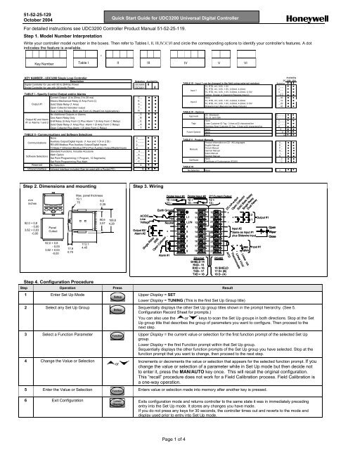
Step 1. Model Number Interpretation<br />
Write your controller model number in the boxes. Then refer to Tables I, II, III,IV,V,VI and circle the corresponding options to identify your controller’s features. A dot<br />
indicates the feature is available.<br />
-<br />
Key Number Table I II III IV V VI<br />
KEY NUMBER - UDC3200 Single Loop Controller<br />
Description<br />
Digital Controller for use with 90 to 264Vac Power<br />
Digital Controller for use with 24Vac/dc Power<br />
TABLE I - Specify Control Output and/or Alarms<br />
Current Output (4 to 20ma, 0 to 20 ma)<br />
Electro Mechanical Relay (5 Amp Form C)<br />
Output #1 Solid State Relay (1 Amp)<br />
Open Collector transistor output<br />
Dual 2 Amp Relays (Both are Form A) (Heat/Cool Applications)<br />
No Additional Outputs or Alarms<br />
One Alarm Relay Only<br />
Output #2 and Alarm<br />
E-M Relay (5 Amp Form C) Plus Alarm 1 (5 Amp Form C Relay)<br />
#1 or Alarms 1 and 2<br />
Solid State Relay (1 Amp) Plus Alarm 1 (5 Amp Form C Relay)<br />
Open Collector Plus Alarm 1 (5 Amp Form C Relay)<br />
TABLE II - Communications and Software Selections<br />
None<br />
Auxiliary Output/Digital Inputs (1 Aux and 1 DI or 2 DI)<br />
Communications<br />
RS-485 Modbus Plus Auxiliary Output/Digital Inputs<br />
10 Base-T Ethernet (Modbus RTU) Plus Auxiliary Output/Digital Inputs<br />
Standard Functions, Includes Accutune<br />
Math Option<br />
Software Selections<br />
Set Point Programming (1 Program, 12 Segments)<br />
Set Point Programming Plus Math<br />
Reserved No Selection<br />
Infrared interface<br />
Infrared Interface Included (Can be used with a Pocket PC)<br />
Selection<br />
DC3200<br />
DC3201<br />
C _<br />
E _<br />
A _<br />
T _<br />
R _<br />
_ 0<br />
_ B<br />
_ E<br />
_ A<br />
_ T<br />
0 _ _ _<br />
1 _ _ _<br />
2 _ _ _<br />
3 _ _ _<br />
_ 0 _ _<br />
_ A _ _<br />
_ B _ _<br />
_ C _ _<br />
_ _ 0 _<br />
_ _ _ R<br />
Availability<br />
Availability<br />
DC 3200 3201<br />
TABLE III - Input 1 can be changed in the field using external resistors<br />
Selection<br />
TC, RTD, mV, 0-5V, 1-5V<br />
1 _ _<br />
TC, RTD, mV, 0-5V, 1-5V, 0-20mA, 4-20mA<br />
2 _ _<br />
Input 1<br />
TC, RTD, mV, 0-5V, 1-5V, 0-20mA, 4-20mA, 0-10V<br />
3 _ _<br />
Carbon, Oxygen or Dewpoint (Requires Input 2) 1 6 0<br />
None<br />
_ 00<br />
TC, RTD, mV, 0-5V, 1-5V, 0-20mA, 4-20mA<br />
_ 10<br />
Input 2<br />
TC, RTD, mV, 0-5V, 1-5V, 0-20mA, 4-20mA, 0-10V<br />
_ 20<br />
Slidewire Input (Requires two Relay Outputs) _ 40<br />
TABLE IV - Options<br />
CE (Standard)<br />
0 _ _ _ _<br />
Approvals<br />
CE, UL and CSA<br />
1 _ _ _ _<br />
None<br />
_ 0 _ _ _<br />
Tags Linen Customer ID Tag - 3 lines w/22 characters/line<br />
_ T _ _ _<br />
Stainless Steel Customer ID Tag - 3 lines w/22 characters/line<br />
_ S _ _ _<br />
None<br />
_ _ 0 _ _<br />
Future Options None<br />
_ _ _ 0 _<br />
None<br />
_ _ _ _ 0<br />
TABLE V - Product Manuals<br />
Product Information on CD - All Languages<br />
0 _<br />
English Manual<br />
E _<br />
French Manual<br />
F _<br />
Manuals<br />
German Manual<br />
G _<br />
Italian Manual<br />
I _<br />
Spanish Manual<br />
S _<br />
None<br />
_ 0<br />
Certificate<br />
Certificate of Conformance (F3391)<br />
_ C<br />
TABLE VI<br />
No Selection None<br />
0 _<br />
Step 2. Dimensions and mounting<br />
Step 3. Wiring<br />
mm<br />
inches<br />
92,0 + 0,8<br />
-0,00<br />
3,62 + 0,03<br />
-0,00<br />
Panel<br />
Cutout<br />
92,0 + 0,8<br />
-0,00<br />
3,62 + 0,03<br />
-0,00<br />
17,9<br />
0,70<br />
Max. panel thickness<br />
19,1<br />
9,0<br />
.75<br />
0,35<br />
113,1<br />
4,45<br />
Step 4. Configuration Procedure<br />
90,6<br />
3,57<br />
108,6<br />
4,28<br />
AC/DC<br />
Line<br />
Voltage<br />
Output #2/<br />
Alarm #2<br />
Digital Input #1<br />
Digital Input #2<br />
10 +<br />
12 +<br />
11 –<br />
13 –<br />
Earth Ground<br />
Alarm #1<br />
Hot<br />
Neutral<br />
+<br />
-<br />
Single Relay<br />
SSR<br />
Open Collector<br />
L1<br />
L2/N<br />
12<br />
4<br />
13<br />
5<br />
6<br />
7<br />
8<br />
9<br />
10<br />
11<br />
14<br />
15<br />
16<br />
17<br />
18<br />
Ethernet<br />
SHIELD 14<br />
RXD - 15<br />
RXD + 16<br />
TXD - 17<br />
TXD + 18<br />
2 nd Current Output<br />
12 +<br />
13 -<br />
19<br />
20<br />
21<br />
22<br />
23<br />
24<br />
25<br />
26<br />
27<br />
RS485<br />
+<br />
16 SHIELD<br />
17 D+ (B)<br />
18 D - (A)<br />
Step Operation Press Result<br />
1 Enter Set Up Mode<br />
2 Select any Set Up Group<br />
Setup<br />
Setup<br />
3 Select a Function Parameter Function<br />
4 Change the Value or Selection<br />
5 Enter the Value or Selection Function<br />
or<br />
+<br />
- -<br />
+<br />
+<br />
+<br />
250<br />
Input #1<br />
- -<br />
-<br />
ohm<br />
Linear mA<br />
Linear V/mV<br />
Thermocouple<br />
RTD<br />
DC mA output<br />
Open Collector<br />
Solid State Relay<br />
Single Relay<br />
Dual Relay<br />
2<br />
1<br />
Input #2<br />
Same as Input #1<br />
plus Slidewire input<br />
Upper Display = SET<br />
Lower Display = TUNING (This is the first Set Up Group title)<br />
Output #1<br />
Open<br />
Wiper<br />
Close<br />
Sequentially displays the other Set Up group titles shown in the prompt hierarchy. (See 5.<br />
Configuration Record Sheet for prompts.)<br />
You can also use the or keys to scan the Set Up groups in both directions. Stop at the Set<br />
Up group title that describes the group of parameters you want to configure. Then proceed to the<br />
next step.<br />
Upper Display = the current value or selection for the first function prompt of the selected Set Up<br />
group.<br />
Lower Display = the first Function prompt within that Set Up group.<br />
Sequentially displays the other function prompts of the Set Up group you have selected. Stop at the<br />
function prompt that you want to change, then proceed to the next step.<br />
Increments or decrements the value or selection that appears for the selected function prompt. If you<br />
change the value or selection of a parameter while in Set Up mode but then decide not<br />
to enter it, press the MAN/AUTO key once. This will recall the original configuration.<br />
This “recall” procedure does not work for a Field Calibration process. Field Calibration is<br />
a one-way operation.<br />
Enters value or selection made into memory after another key is pressed.<br />
6 Exit Configuration Lower<br />
Display<br />
Exits configuration mode and returns controller to the same state it was in immediately preceding<br />
entry into the Set Up mode. It stores any changes you have made.<br />
If you do not press any keys for 30 seconds, the controller times out and reverts to the mode and<br />
display used prior to entry into Set Up mode.<br />
Page 1 of 4
51-52-25-129<br />
October 2004<br />
<strong>Quick</strong> <strong>Start</strong> Guide for UDC3200 Universal Digital Controller<br />
Step 5. Configuration Record Sheet<br />
Enter the value or selection for each prompt on this sheet so you will have a record of how your controller was configured.<br />
Group Prompt Function Prompt Value or<br />
Selection<br />
TUNING<br />
SPRAMP<br />
ACCUTUNE<br />
ALGOR<br />
OUTALG<br />
INPUT1<br />
PROP BD or GAIN<br />
GAINVALn<br />
RATE MIN<br />
RSET MIN or RSET RPM<br />
MAN RSET<br />
PROPBD2 or GAIN 2<br />
RATE2MIN<br />
RSET2MIN or RSET2RPM<br />
CYC SEC or CYC SX3<br />
CYC2 SEC or CYC2 SX3<br />
SECURITY<br />
LOCKOUT<br />
AUTO MAN<br />
SP SEL<br />
RUN HOLD<br />
SP RAMP<br />
TIME MIN<br />
FINAL SP<br />
HOTSTART<br />
SP RATE<br />
EU/HR UP<br />
EU/HR DN<br />
HOTSTART<br />
SP PROG<br />
FUZZY<br />
ACCUTUNE<br />
DUPLEX<br />
AT ERROR<br />
CONT ALG<br />
TIMER<br />
PERIOD<br />
START<br />
L DISP<br />
INP ALG1<br />
MATH K<br />
CALC HI<br />
CALC LO<br />
ALG1 INA<br />
ALG1 INB<br />
ALG1 INC<br />
ALG1BIAS<br />
PCT CO<br />
OUT ALG<br />
RLYSTATE<br />
RLY TYPE<br />
MOTOR TI<br />
CUR OUT<br />
CO RANGE<br />
LOW VAL<br />
HIGH VAL<br />
IN1 TYPE<br />
XMITTER1<br />
IN1 HIgh<br />
IN1 LOw<br />
RATIO1<br />
BIAS IN1<br />
FILTER1<br />
BURNOUT1<br />
EMMISIV1<br />
_______<br />
READ ONLY<br />
_______<br />
_______<br />
_______<br />
_______<br />
_______<br />
_______<br />
_______<br />
_______<br />
_______<br />
_______<br />
_______<br />
_______<br />
_______<br />
_______<br />
_______<br />
_______<br />
_______<br />
_______<br />
_______<br />
_______<br />
_______<br />
_______<br />
_______<br />
_______<br />
_______<br />
Read Only<br />
_______<br />
_______<br />
_______<br />
_______<br />
_______<br />
_______<br />
_______<br />
_______<br />
_______<br />
_______<br />
_______<br />
_______<br />
_______<br />
_______<br />
_______<br />
_______<br />
_______<br />
_______<br />
_______<br />
_______<br />
_______<br />
_______<br />
_______<br />
_______<br />
_______<br />
_______<br />
_______<br />
_______<br />
_______<br />
_______<br />
_______<br />
Factory<br />
Setting<br />
1.000<br />
----<br />
0.00<br />
1.0<br />
0.0<br />
1.00<br />
0.00<br />
1.00<br />
20<br />
20<br />
0<br />
CALIB<br />
ENABLE<br />
ENABLE<br />
ENABLE<br />
DISABLE<br />
3<br />
1000<br />
DISABLE<br />
DISABLE<br />
0<br />
0<br />
DISABLE<br />
DISABLE<br />
DISABLE<br />
DISABLE<br />
MANUAL<br />
NONE<br />
PIDA<br />
DIS<br />
0:01<br />
KEY<br />
TREM<br />
KEY<br />
MIN<br />
CURRENT<br />
1 OF 2 ON<br />
MECHAN<br />
30<br />
DISABLE<br />
4-20Ma<br />
0.0<br />
100.0<br />
0-10mV<br />
LINEAR<br />
1000<br />
0<br />
1.00<br />
0.0<br />
1<br />
NONE<br />
0.00<br />
Group Prompt Function Prompt Value or<br />
Selection<br />
INPUT2<br />
CONTRL<br />
OPTION<br />
COM<br />
ALARMS<br />
DISPLY<br />
IN2 TYPe<br />
XMITTER2<br />
IN2 HIgh<br />
IN2 LOw<br />
RATIO2<br />
BIAS IN2<br />
FILTER2<br />
BURNOUT2<br />
EMMISIV2<br />
PV SOURC<br />
PID SETS<br />
SW VALUE<br />
LSP’S<br />
RSP SRC<br />
AUTO BIAS<br />
SP TRACK<br />
PWR MODE<br />
PWR OUT<br />
SP HiLIM<br />
SP LoLIM<br />
ACTION<br />
OUT RATE<br />
PCT/M UP<br />
PCT/M DN<br />
OUT HiLIM<br />
OUT LoLIM<br />
I Hi LIM<br />
I Lo LIM<br />
DROPOFF<br />
DEADBAND<br />
OUT HYST<br />
FAILMODE<br />
FAILSAFE<br />
MAN AUTO<br />
AUTO OUT<br />
PBorGN<br />
MINRPM<br />
AUXOUT<br />
CO RANGE<br />
LOW VAL<br />
HIGH VAL<br />
DIG INP 1<br />
DIG1 COMB<br />
DIG INP 2<br />
DIG2 COMB<br />
ComSTATE<br />
Com ADDR<br />
IR ENABLE<br />
BAUD<br />
TX_DELAY<br />
WSFLOAT<br />
SHEDENAB<br />
SHEDTIME<br />
SHEDMODE<br />
SHDSP<br />
UNITS<br />
CSP RATO<br />
CSP_BIAS<br />
LOOPBACK<br />
A1S1 VA<br />
A1S2 VA<br />
A2S1 VA<br />
A2S2 VA<br />
A1S1TYPE<br />
A1S2TYPE<br />
A2S1TYPE<br />
A2S2TYPE<br />
A1S1 HL<br />
A1S1 EV<br />
A1S2 HL<br />
A1S2 EV<br />
A2S1HL<br />
A2S1EV<br />
A2S2HL<br />
A2S2EV<br />
ALHYST<br />
ALM OUT1<br />
BLOCK<br />
DIAGNOST<br />
DECIMAL<br />
TEMPUNIT<br />
PWR FREQ<br />
RATIO 2<br />
LANGUAGE<br />
_______<br />
_______<br />
_______<br />
_______<br />
_______<br />
_______<br />
_______<br />
_______<br />
_______<br />
_______<br />
_______<br />
_______<br />
_______<br />
_______<br />
_______<br />
_______<br />
_______<br />
_______<br />
_______<br />
_______<br />
_______<br />
_______<br />
_______<br />
_______<br />
_______<br />
_______<br />
_______<br />
_______<br />
_______<br />
_______<br />
_______<br />
_______<br />
_______<br />
_______<br />
_______<br />
_______<br />
_______<br />
_______<br />
_______<br />
_______<br />
_______<br />
_______<br />
_______<br />
_______<br />
_______<br />
_______<br />
_______<br />
_______<br />
_______<br />
_______<br />
_______<br />
_______<br />
_______<br />
_______<br />
_______<br />
_______<br />
_______<br />
_______<br />
_______<br />
_______<br />
_______<br />
_______<br />
_______<br />
_______<br />
_______<br />
_______<br />
_______<br />
_______<br />
_______<br />
_______<br />
_______<br />
_______<br />
_______<br />
_______<br />
_______<br />
_______<br />
_______<br />
_______<br />
_______<br />
_______<br />
_______<br />
_______<br />
_______<br />
_______<br />
Factory<br />
Setting<br />
1-10mV<br />
LINEAR<br />
1000<br />
0<br />
1.00<br />
0<br />
1<br />
NONE<br />
0.00<br />
INPUT 1<br />
1 ONLY<br />
0.00<br />
1 ONLY<br />
NONE<br />
DISABLE<br />
NONE<br />
MANUAL<br />
LAST<br />
1000<br />
0<br />
REVERSE<br />
DISABLE<br />
0<br />
0<br />
100<br />
0.0<br />
100.0<br />
0.0<br />
0<br />
1.0<br />
0.5<br />
NO LATCH<br />
0.0<br />
---<br />
---<br />
GAIN<br />
MIN<br />
DISABLE<br />
4-20mA<br />
0.O<br />
100.0<br />
NONE<br />
DIS ABLE<br />
NONE<br />
DISABLE<br />
DISABLE<br />
3<br />
ENABLE<br />
19200<br />
1<br />
FP_B<br />
DISABLE<br />
30.0<br />
LAST<br />
TP LSP<br />
PERCNT<br />
1.0<br />
0<br />
DISABLE<br />
90<br />
10<br />
95<br />
5<br />
NONE<br />
NONE<br />
NONE<br />
NONE<br />
HIGH<br />
--<br />
LOW<br />
--<br />
HIGH<br />
--<br />
LOW<br />
--<br />
0.1<br />
NO LAT<br />
DISABLE<br />
DISABLE<br />
XXXX<br />
NONE<br />
60 HZ<br />
DISABLE<br />
ENGLISH<br />
Page 2 of 4
51-52-25-129<br />
October 2004<br />
<strong>Quick</strong> <strong>Start</strong> Guide for UDC3200 Universal Digital Controller<br />
(Ethernet addresses are accessible via PIE Tool)<br />
Step 6. <strong>Start</strong> Up Procedure for Operation<br />
Step Operation Press Result<br />
1 Select Manual<br />
Mode<br />
Man<br />
Auto<br />
Until “M” indicator is ON.<br />
The controller is in manual mode.<br />
2 Adjust the Output or To adjust the output value and ensure that the final control element is functioning correctly.<br />
Upper Display = PV Value<br />
Lower Display = OUT and the output value in %<br />
3 Enter the Local<br />
Setpoint<br />
4 Select Automatic<br />
Mode<br />
5 Tune the<br />
Controller<br />
Lower<br />
Display<br />
Upper Display = PV Value<br />
Lower Display = SP and the Local Setpoint Value<br />
or To adjust the local setpoint to the value at which you want the process variable maintained.<br />
The local setpoint cannot be changed if the Setpoint Ramp function is running.<br />
Man<br />
Auto<br />
Setup<br />
Until “A” indicator is ON.<br />
The controller is in Automatic mode.<br />
The controller will automatically adjust the output to maintain the process variable at setpoint.<br />
Make sure the controller has been configured properly and all the values and selections have<br />
been recorder on the Configuration Record Sheet.<br />
Refer to Tuning Set Up group to ensure that the selections for PBor GAIN, RATE T, and I<br />
MIN, or I RPM have been entered.<br />
Use ACCUTUNE to tune the controller.<br />
Procedure for Changing the Local Setpoints<br />
Step Operation Press Result<br />
1 Select the<br />
Setpoint<br />
2 Change the<br />
Value<br />
Lower<br />
Display<br />
or<br />
Additional Operating Procedures<br />
Until you see:<br />
Upper Display = PV<br />
Lower Display = SP or 2SP or 3SP (Value)<br />
To change the Local Setpoint to the value at which you want the process maintained. The<br />
display “blinks” if you attempt to enter setpoint values beyond the high and low limits..<br />
3 Return to PV<br />
Display<br />
Lower<br />
Display<br />
To store immediately or will store after 30 seconds.<br />
Procedure for Switching Between Setpoints<br />
You can switch Local and Remote setpoints or between two Local setpoints when configured.<br />
ATTENTION The REMOTE SETPOINT value cannot be changed at the keyboard.<br />
Step Operation Press Result<br />
1 Select the<br />
Setpoint<br />
SP<br />
Select<br />
To switch between the Three Local Setpoints and/or the Remote Setpoint.<br />
ATTENTION “KEY ERROR” will appear in the<br />
lower display, if:<br />
• the remote setpoint or additional local setpoints are not configured as a setpoint source<br />
• you attempt to change the setpoint while a setpoint ramp is enabled, or<br />
• if you attempt to change the setpoint with the setpoint select function key disabled.<br />
Page 3 of 4
51-52-25-129<br />
October 2004<br />
<strong>Quick</strong> <strong>Start</strong> Guide for UDC<strong>2500</strong> Limit Controller<br />
Viewing the Operating Parameters<br />
Press the LOWER DISPLAY key to scroll through the operating parameters listed.<br />
The lower display will show only those parameters and their values that apply to your specific model.<br />
Lower Display<br />
OUT XX.X<br />
SP XXXX<br />
Lower Display Key Parameter Prompts<br />
Description<br />
OUTPUT—Output value is shown in percent with one decimal point for all output types except<br />
Three Position Step Control (TPSC). For TPSC, when no slidewire is connected, this display is<br />
an estimated motor position and is shown with no decimal point.<br />
For Position Proportional Control, if the slidewire fails, then the instrument automatically<br />
switches over to TPSC and the OUT display changes with it.<br />
LOCAL SETPOINT #1—Also current setpoint when using SP Ramp.<br />
2SP XXXX LOCAL SETPOINT #2<br />
3SP XXXX LOCAL SETPOINT #3<br />
RSP XXXX<br />
1IN XXXX<br />
2IN XXXX INPUT 2<br />
POS XX<br />
CSP XXXX<br />
REMOTE SETPOINT<br />
INPUT 1—Used only with combinational input algorithms.<br />
SLIDEWIRE POSITION—Used only with TPSC applications that use a slidewire input.<br />
COMPUTER SETPOINT—When SP is in override.<br />
DEV XXXX DEVIATION—Maximum negative display is –999.9.<br />
PIDSET X TUNING PARAMETER —where X is either 1 or 2.<br />
ET HR.MN<br />
OTR HR.MN<br />
RAMPXXXM<br />
SPN XXXX<br />
XXRAHR.MN<br />
XXSKHR.MN<br />
RECYC XX<br />
To BEGIN<br />
RERUN<br />
AUX XXXX<br />
BIA XXXX<br />
TUNE OFF<br />
ELAPSED TIME—Time that has elapsed on the Timer in Hours.Minutes.<br />
TIME REMAINING—Time remaining on the Timer in Hours.Minutes. The “O” is a rotating clock<br />
face.<br />
SETPOINT RAMP TIME—Time remaining in the Setpoint Ramp in minutes.<br />
SETPOINT NOW—Current Setpoint when SP Rate is enabled. The SP XXXX display shows the<br />
“target” or final setpoint value.<br />
RAMP SEGMENT NUMBER AND TIME REMAINING—Set Point Programming display. XX is<br />
the current segment number and HR.MN is the time remaining for this segment in<br />
Hours.Minutes.<br />
SOAK SEGMENT NUMBER AND TIME REMAINING— Set Point Programming display. XX is<br />
the current segment number and HR.MN is the time remaining for this segment in<br />
Hours.Minutes.<br />
NUMBER OF SP PROGRAM RECYCLES REMAINING<br />
RESET SP PROGRAM TO START OF FIRST SEGMENT<br />
RESET SP PROGRAM TO START OF CURRENT SEGMENT<br />
AUXILIARY OUTPUT—Displayed only when output algorithm is not Current Duplex.<br />
BIAS—Displays the manual reset value for algorithm PD+MR.<br />
LIMIT CYCLE TUNING NOT RUNNING—Appears when Accutune is enabled but not operating.<br />
DO FAST<br />
DO SLOW<br />
Limit Cycle Tuning with the objective of producing quarter-damped tuning parameters. This<br />
tuning may result in PV overshoot of the SP setting.<br />
Limit Cycle Tuning with the objective of producing damped or Dahlin tuning parameters,<br />
depending upon the detected process deadtime. The tuning parameters calculated by this<br />
selection are aimed at reducing PV overshoot of the SP setting.<br />
Page 4 of 4


