

Accessories - Grundfos
Accessories - Grundfos
Accessories - Grundfos

Create successful ePaper yourself
Turn your PDF publications into a flip-book with our unique Google optimized e-Paper software.
<strong>Accessories</strong><br />
BMB<br />
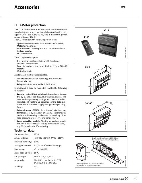
CU 3 Motor protection<br />
The CU 3 control unit is an electronic motor starter for<br />
monitoring and protecting installations with rated voltages<br />
of 200 - 575 V, 50/60 Hz, and a maximum power<br />
consumption of 400 A.<br />
The CU 3 monitors the following parameters:<br />
R100<br />
CU 3<br />
System insulation resistance to earth before start.<br />
Motor temperature.<br />
Motor current consumption and current unbalance.<br />
Voltage supply.<br />
Phase sequence.<br />
The CU 3 protects against:<br />
GR0244 - GR1911<br />
Dry running (not for certain MS 402 motors).<br />
Incipient motor defect.<br />
Excessive motor temperature (not for certain MS 402<br />
motors).<br />
Motor burnout.<br />
CU 3<br />
192.5 mm<br />
54.5 mm<br />
As standard, the CU 3 incorporates:<br />
• Time relay for star-delta starting and autotransformer<br />
starting.<br />
• Relay output for external fault indication.<br />
In addition CU 3 can be expanded to offer the following<br />
functions:<br />
• Remote control R100: Wireless infra-red remote control<br />
by means of the R100. This function enables the<br />
user to change factory settings and to monitor the<br />
installation by calling up actual operating data, e.g.<br />
current consumption, supply voltage and operating<br />
hours.<br />
200 mm<br />
SM100<br />
192.5 mm<br />
54.5 mm<br />
TM00 7308 1102<br />
• External sensors SM100: Reception of data from external<br />
sensors by means of an SM100 sensor module<br />
and control according to the data received, e.g. flow<br />
rate, pressure, water level and conductivity.<br />
• Communication module: Monitoring and communication<br />
via a data BUS (GENIbus), a modem or radio,<br />
e.g. PC-based control/monitoring.<br />
Technical data<br />
00 mm<br />
TM01 4020 1102<br />
Enclosure class: IP 20.<br />
Ambient temp.: –20°C to +60°C (–4°F to +140°F).<br />
Relative humidity: 99%.<br />
Single-turn transformers, 100-400 A.<br />
No monitoring of motor temperature.<br />
Voltage variation:<br />
–25/+15% of nominal voltage.<br />
100 mm<br />
Frequency:<br />
45 Hz to 65 Hz.<br />
Max. back-up fuse: 10 A.<br />
106 mm<br />
Relay output: Max. 415 V, 3 A, AC 1.<br />
Approvals:<br />
The CU 3 complies with: VDE,<br />
DEMKO, EN, UL and CSA.<br />
Marking:<br />
CE.<br />
89 mm<br />
50 mm<br />
330 mm<br />
Signal converter, 1-12 A/20-120 A, with<br />
monitoring of motor temperature.<br />
50 mm<br />
TM00 7866 1096<br />
41
<strong>Accessories</strong><br />
BMB<br />
Product numbers<br />
Product<br />
number<br />
CU 3 - 3 x 400 V<br />
Current range for signal converter [A]<br />
1-12 10-120 100-400<br />
62500293 z<br />
62500294 z<br />
62500295 z<br />
CU 3 - 3 x 460 V<br />
62500247 z<br />
62500248 z<br />
62500249 z<br />
CU 3 - 3 x 575 V<br />
62500253 z<br />
62500254 z<br />
62500255 z<br />
Product<br />
Single-turn transformers<br />
CU 3 expansion possibilities<br />
Range<br />
Product<br />
number<br />
Sensor module SM 100 3 x 400 [V] 00626191<br />
3 x 460 [V] 00626192<br />
Communication module RS 485 - 00626159<br />
DIN-Rail mounting 00626156<br />
Remote control R100<br />
HP printer for R100<br />
Signal converter<br />
-<br />
-<br />
00625333<br />
00620480<br />
1 - 12 [A] 00620497<br />
10 - 120 [A] 00620498<br />
100 - 400 [A] 00626148<br />
Control functions<br />
This table describes the protection provided by CU 3.<br />
Control parameters Function Problem Advantages<br />
Ground failure<br />
Temperature<br />
Overvoltage/<br />
undervoltage<br />
Overload<br />
Dry running<br />
Current unbalance<br />
Phase sequence<br />
Insulation resistance is measured only when the motor is not<br />
operating. A high-impedance voltage is applied to the motor<br />
leads and leakage to ground is measured.<br />
If the factory-set value is higher than the one measured, the<br />
motor cannot be started.<br />
Damaged or decomposed insulation<br />
in<br />
• motor,<br />
• cable or cable joint.<br />
• Overload,<br />
MS 4000 and MS 6000.<br />
• frequent starts/stops,<br />
The actual motor temperature is measured by means of the<br />
built-in Tempcon temperature transmitter and a signal is sent<br />
• operation against blocked<br />
to CU 3 via the phase leads. CU 3 compared the measured temperature<br />
discharge pipe,<br />
with the factory-set value.<br />
• insufficient flow velocity past<br />
the motor.<br />
If the factory-set values are exceeded, a fault indication is<br />
given. If the CU 3 receives a temperature signal, the voltage is<br />
no longer monitored, but the motor will continue to run.<br />
Therefore, the motor and consequently the pump operation<br />
will only be affected by voltage variations critical to the life of<br />
the motor.<br />
If there is no temperature signal, the motor will be stopped in<br />
case of overvoltage/undervoltage.<br />
The motor power input is measured on each of the three<br />
phases. The registered power input is an average of these<br />
three values.<br />
If the factory-set value is exceeded, the motor will stop.<br />
The motor power input is measured on each of the three<br />
phases. The registered power input is an average of these<br />
three values.<br />
If the average value is lower than the factory-set value, the<br />
motor will stop.<br />
The motor power input is measured on each of the three<br />
phases.<br />
CU 3 and motor are installed so that the phase sequence corresponds<br />
to correct direction of rotation.<br />
CU 3 monitors changes in the phase sequences.<br />
• The installation is close to a<br />
transformer,<br />
• the mains do not absorb load<br />
variations.<br />
• Incorrect dimensioning of<br />
pump/motor,<br />
• voltage supply failure,<br />
• defective cable,<br />
• blocking,<br />
• wear or corrosion.<br />
Pump exposed to dry running or<br />
underload, for example caused by<br />
wear.<br />
• Mains load is uneven,<br />
• incipient motor defect,<br />
• phase voltages diverging.<br />
Two phases are wrongly connected.<br />
• Possibility of indication<br />
of failure/of motor,<br />
cable and cable joint,<br />
• service indication.<br />
• Longer motor life,<br />
• safe operating<br />
conditions,<br />
• service indication.<br />
• Important installation<br />
parameter,<br />
• possibility of improving<br />
operating conditions.<br />
• Longer motor life,<br />
• safe operating<br />
conditions,<br />
• service indication.<br />
• Traditional dry-running<br />
protection is no longer<br />
necessary,<br />
• no extra cables.<br />
• Motor protection<br />
against overload,<br />
• service indication.<br />
Ensures correct pump<br />
performance.<br />
42
<strong>Accessories</strong><br />
BMB<br />
MTP 75 Motor protection<br />
Long motor life<br />
The MTP 75 protects against excessive motor temperature.<br />
This is the most simple and the most economical<br />
way of ensuring long motor life. The user is certain that<br />
operating conditions are observed and is given indication<br />
of the time when a service check should be made.<br />
Excessive motor temperature may be caused by:<br />
• Overload<br />
• Frequent starting/stopping (hunting)<br />
• Operation against closed valve/frozen discharge pipe<br />
• Insufficient flow of liquid past the motor<br />
• Pumping of water that is too hot<br />
• Deposits on the motor<br />
• Overvoltage<br />
• Undervoltage<br />
• Current unbalance<br />
• Dry running (Note that the pump is not protected if<br />
the water level is below the pump inlet.<br />
Application and installation<br />
The MTP 75 can be used only for motors with built-in<br />
temperature transmitter and should be installed for<br />
instance in a control cabinet. The MTP 75 may be<br />
installed in any type of control cabinet containing a<br />
thermal relay with differential release and contactor.<br />
The thermal relay is necessary to protect against<br />
blocking or phase failure, since this will cause the<br />
temperature to rise much faster than the MTP 75 is able<br />
to register.<br />
The MTP 75 is supplied with base for mounting on DIN<br />
rail.<br />
Operation<br />
The temperature transmitter will send a high-frequency<br />
signal indicating the motor temperature through the motor<br />
supply cable. The MTP 75 will stop the motor via the<br />
contactor if the temperature rises above 75°C (167°F). The<br />
temperature limit is factory-set and cannot be changed.<br />
Display:<br />
No light: Motor stopped. No supply voltage or electrical<br />
fault at temperature measuring.<br />
Green light: Motor in operation and motor temperature<br />
OK, i.e. below 75°C (167°F).<br />
Red light: Motor stopped and motor temperature too<br />
high, i.e. above 75°C (167°F).<br />
The MTP 75 is reset manually by pressing the reset<br />
button on the front cover or by switching off the voltage<br />
supply to the MTP 75.<br />
No unnecessary downtime<br />
Since the MTP 75 measures only the temperature and no<br />
other parameters causing a temperature rise, the motor<br />
and thus the pump will stop only when the motor<br />
temperature is too high.<br />
Reliability<br />
The MTP 75 is reliable due to its simple construction and<br />
because it requires no extra cables in the piping.<br />
Technical data of MTP 75<br />
Supply voltage:<br />
Control voltage:<br />
Enclosure class: IP 20.<br />
Operating conditions:<br />
Storage:<br />
2 variants:<br />
1 x 200-240 V ±10%, 50/60 Hz.<br />
3 x 380-415 V ±10%, 50/60 Hz.<br />
A transformer is required for<br />
voltages over 415 V.<br />
Contact load:<br />
Maximum 415 V/3 A.<br />
Minimum 12 V/20 mA.<br />
Min. temperature: –20°C (–4°F).<br />
Max. temperature:<br />
+60°C (+140°F).<br />
Relative humidity: 99%.<br />
Min. temperature: –20°C (–4°F).<br />
Max. temperature:<br />
+60°C (+140°F)<br />
Relative humidity: 99%.<br />
Approvals:<br />
Complying with the regulations<br />
of VDE and DEMKO.<br />
Product numbers<br />
MTP 75 without plug-in base, capacitor and signal transformer:<br />
Voltage range [V]<br />
GR 1915<br />
Product number<br />
1 x 200-240 00625178<br />
3 x 380-415 00625179<br />
MTP 75 complete with plug-in base, capacitor and signal<br />
transformer:<br />
Voltage range [V]<br />
78 mm<br />
35 mm<br />
104 mm<br />
Product number<br />
1 x 200-240 00625804<br />
3 x 380-415 00625805<br />
TM00 7874 1102<br />
43
e i us DI Se ce<br />
o t<br />
Ma n<br />
e wo k<br />
C n ec on<br />
o 2<br />
S<br />
<strong>Accessories</strong><br />
BMB<br />
G100 - Gateway for communication<br />
with <strong>Grundfos</strong> products<br />
The G100 offers a wide selection of options for integration<br />
of <strong>Grundfos</strong> products provided with GENIbus interface<br />
into main control and monitoring systems.<br />
The G100 enables a pump installation to meet future<br />
demands for optimum pump operation in terms of reliability,<br />
operating costs, centralization and automation.<br />
GR5940<br />
Central management system<br />
Radio<br />
Radio<br />
Modem<br />
SMS<br />
PLC<br />
Direct<br />
Interbus-S<br />
Profibus-DP<br />
4 digital inputs<br />
Main network<br />
RS-232<br />
Service<br />
port for pc<br />
Heating<br />
UPE TPE UPS<br />
Water treatment<br />
Industry<br />
CU<br />
E-<br />
300 CU 3 CU 3 CU 3 CU 3 pump DME<br />
BMQE-<br />
NE<br />
BMB<br />
BM BMET CRN<br />
Water supply<br />
GENIbus<br />
Multi-E<br />
Control<br />
2000<br />
MGE<br />
E-<br />
pump CU 3<br />
Wastewater<br />
MG<br />
Hydro<br />
2000<br />
SM100 CU 3 CU 3 CU 3 CU 3<br />
CR NK SP-G SP<br />
CU 300<br />
SQE<br />
Multi-E<br />
SM<br />
SM<br />
CU 3<br />
100 100<br />
Sensors<br />
Sensors<br />
AP<br />
Sensors<br />
TM01 1804 1102<br />
44
S<br />
S<br />
<strong>Accessories</strong><br />
BMB<br />
Product description<br />
The G100 Gateway enables communication of operating<br />
data, such as measured values, setpoints, etc., between<br />
<strong>Grundfos</strong> products with GENIbus interface and a main<br />
network for control and monitoring.<br />
As indicated in the illustration on page 44, the G100 is<br />
suitable for use in applications such as water supply,<br />
water treatment, wastewater, building automation and<br />
industry.<br />
Common to above applications is that downtime is<br />
usually costly, and extra investments are therefore often<br />
made to achieve maximum reliability by monitoring<br />
selected operating variables.<br />
The day-to-day operation, such as starting and stopping<br />
of pumps, changing of setpoints, etc., can also be<br />
effected from the main system by communication with<br />
the G100. In addition, the G100 can be set up to send<br />
event-controlled status indications such as alarms via<br />
the SMS to mobile phones, and to make automatic alarm<br />
call-backs to a central management system.<br />
Data logging<br />
Besides the possibility of data communication, the G100<br />
also offers logging of up to 350,000 time-stamped data.<br />
Subsequently, the logged data can be transmitted to the<br />
main system or a PC for further analysis in a spreadsheet<br />
or similar program.<br />
For the data logging, the "PC Tool G100 Data Log" software<br />
tool is used. The tool is part of the PC Tool G100<br />
package, which must be ordered separately.<br />
Other features<br />
• Four digital inputs.<br />
• Stop of all pumps in case of failing communication<br />
with the management system (optional).<br />
• Access code for modem communication (optional).<br />
• Alarm log.<br />
Installation<br />
Installation of the G100 is effected by the system integrator.<br />
The G100 is connected to the GENIbus as well as<br />
to the main network. Subsequently, all units on the<br />
GENIbus can be controlled from a central management<br />
system on the main network.<br />
The "G100 Support Files" CD-ROM supplied with the<br />
G100 contains examples of programs to be used when<br />
the G100 is connected to the various main network<br />
systems. Included is also a description of the data points<br />
available in <strong>Grundfos</strong> products with GENIbus interface.<br />
The "PC Tool G100" software tool can be used for the<br />
G100 installation and use. To be ordered separately.<br />
227 mm<br />
Technical data<br />
Overview of protocols<br />
Main system<br />
INTERBUS-S<br />
PROFIBUS-DP<br />
Radio<br />
Modem<br />
PLC<br />
GSM mobile phone<br />
Other possible connections<br />
GENIbus RS-485:<br />
Service port<br />
RS-232:<br />
Digital inputs: 4.<br />
Connection of up to 32 units.<br />
For direct connection to a PC<br />
or via radio modem.<br />
Voltage supply: 1 x 110-240 V, 50/60 Hz<br />
Ambient temperature: In operation:<br />
–20°C to +60°C (–4°F to +140°F)<br />
Enclosure class: IP 20<br />
Weight:<br />
1.8 kg. (4.0 lbs)<br />
<strong>Accessories</strong><br />
• PC Tool G100 package (to be ordered separately)<br />
• G100 Support Files CD-ROM (supplied with product)<br />
Product numbers<br />
73 mm 165 mm<br />
*Floppy disk with G100 Support Files included.<br />
Software protocol<br />
PCP<br />
DP<br />
Satt Control COMLI/Modbus<br />
Satt Control COMLI/Modbus<br />
Satt Control COMLI/Modbus<br />
SMS, UCP<br />
Product<br />
Product<br />
number<br />
G100 with Interbus-S expansion board* 96411134<br />
G100 with Profibus-DP expansion board* 96411135<br />
G100 with Radio/Modem/PLC-expansion board* 96411136<br />
G100 Basic Version* 96411137<br />
PC Tool G100 package 96415783<br />
TM01 0621 1102<br />
45
<strong>Accessories</strong><br />
BMB 4”<br />
BMB 4"<br />
Photo of parts Description Specification Part no.<br />
TM00 3702 0894<br />
Victaulic coupling liner for welding<br />
ø42 x 30 mm<br />
N-version 00100517<br />
R-version 00100971<br />
TM00 3703 0894<br />
Victaulic coupling liner with external<br />
thread<br />
R 1¼ x 100 mm/BSPT<br />
N-version 00100534<br />
R-version 00100965<br />
TM00 3705 0894<br />
Victaulic style 77 coupling<br />
ø42 mm x 1¼"<br />
NBR seal<br />
FKM seal<br />
00ID6786<br />
00ID6742<br />
NBR seal N-version 00105563<br />
TM00 3707 0894<br />
Connecting kit for welding, straight<br />
NBR seal R-version 00105982<br />
FKM seal N-version 00105565<br />
FKM seal R-version 00105981<br />
TM00 3711 0894<br />
180° bend for welding,<br />
ø42mm/1¼"<br />
Center distance: 165 mm/6.5 inch<br />
Total height: 127 mm/5.0 inch<br />
R-version 00 15 59 26<br />
NBR seal N-version 00105564<br />
TM00 3708 0894<br />
Connecting kit R 1¼"<br />
NBR seal R-version 00105980<br />
FKM seal N-version 00105566<br />
FKM seal R-version 00105979<br />
TM01 9906 3400<br />
Terminal box kit complete, 4" motor with:<br />
• 1 box including all necessary fittings for mounting on the booster<br />
module.<br />
• 1 mounting bracket<br />
• L x W x H = 80 mm x 75 mm x 60 mm<br />
96446948<br />
TM01 9907 3400<br />
Bracket, 4" 96449565<br />
46
<strong>Accessories</strong><br />
BMB 6"<br />
BMB 6"<br />
Photo of parts Description Specification Part no.<br />
TM00 3709<br />
Victaulic coupling liner for welding<br />
ø89 x 50 mm<br />
3" x 2"<br />
N-version 00150574<br />
R-version 00140968<br />
TM00 3711 0894<br />
180° bend for welding,<br />
ø89 mm/3"<br />
Center distance: 300 mm/11.8 inch<br />
Total height = 210 mm/8.3 inch<br />
N-version 00155544<br />
R-version 00155971<br />
TM00 3712 0894<br />
Victaulic style 77 coupling<br />
ø89 mm x 3"<br />
NBR seal<br />
00ID7664<br />
TM00 3714 0894<br />
Connecting kit for welding, straight<br />
NBR seal, N-version 00155542<br />
NBR seal, R-version 00155973<br />
TM00 3715 0894<br />
Connecting kit, 180°<br />
NBR seal, N-version 00155543<br />
NBR seal, R-version 00155972<br />
Terminal box kit complete, 6" motor with:<br />
• 1 box including all necessary fittings for mounting on the<br />
booster module<br />
• L x W x H = 120 mm x 120 mm x 90 mm<br />
TM02 4209 0202<br />
96476716<br />
TM01 9907 3400<br />
Bracket, 6" 96439184<br />
47
<strong>Accessories</strong><br />
BMB 8"<br />
BMB 8"<br />
Photo of parts Description Specification Part no.<br />
TM00 3712 0894<br />
Victaulic style 77 coupling<br />
3": ø89 mm<br />
4": ø114 mm<br />
5": ø139 mm<br />
6": ø168 mm<br />
NBR seal 3"<br />
00ID7664<br />
NBR seal 4" 96415463<br />
NBR seal 5" 96416739<br />
NBR seal 6"<br />
00ID2279<br />
N-version 3" 00150574<br />
TM00 3709<br />
Victaulic coupling liner for welding<br />
Terminal box kit complete, 8" motor with:<br />
• 1 box including all necessary fittings for mounting on the<br />
booster module<br />
• L x W x H = 200 mm x 200 mm x 120 mm<br />
N-version 4" 96416743<br />
N-version 5" 96416744<br />
N-version 6" 96416745<br />
96446950<br />
TM02 4208 0202<br />
TM01 9907 3400<br />
Bracket, 8" 96416762<br />
48


