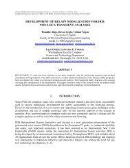
Description of Natural Circulation Systems in the SMART - UxC
Description of Natural Circulation Systems in the SMART - UxC
Description of Natural Circulation Systems in the SMART - UxC

Create successful ePaper yourself
Turn your PDF publications into a flip-book with our unique Google optimized e-Paper software.
<strong>Description</strong> <strong>of</strong> <strong>Natural</strong> <strong>Circulation</strong> <strong>Systems</strong><br />
<strong>in</strong> <strong>the</strong> <strong>SMART</strong> Nuclear Power Plant Design<br />
Young-Jong Chung*<br />
Korea Atomic Energy Research Institute
CONTENTS<br />
Introduction<br />
<strong>Description</strong> <strong>of</strong> Primary Coolant System<br />
<strong>Description</strong> <strong>of</strong> Passive Residual Heat Removal System<br />
<strong>Description</strong> <strong>of</strong> Emergency Cooldown Tank<br />
Conclusions<br />
KAERI 2
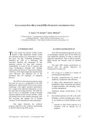
INTRODUCTION – <strong>SMART</strong> Plant<br />
<strong>SMART</strong> DESIGN<br />
Small sized <strong>in</strong>tegral type Pressurized Water Reactor<br />
Elim<strong>in</strong>ation <strong>of</strong> <strong>the</strong> possibility <strong>of</strong> LBLOCA<br />
Self controlled pressurizer by a non-condensable gas<br />
Low power density and Boron free core<br />
Passive system for <strong>the</strong> decay heat removal<br />
Simplification <strong>of</strong> system/components<br />
MCP<br />
CEDM<br />
Annular Cover<br />
Pressurizer<br />
Steam Generator<br />
CHARACTERISTICS<br />
Enhance safety compar<strong>in</strong>g with exist<strong>in</strong>g PWR<br />
Shorten construction period<br />
Reduce liquid radioactive wastes<br />
Reactor Vessel<br />
Core<br />
Side Screen<br />
Displacer<br />
KAERI 3
INTRODUCTION – <strong>SMART</strong> Plant<br />
<strong>SMART</strong> Plant<br />
Multi-purposed plant; sea water desal<strong>in</strong>ation and power generation<br />
Designed to supply 40,000 ton <strong>of</strong> water and 90 MW <strong>of</strong> electricity<br />
Major components<br />
• Vessel :Height-10.6m, Outer diameter-4.6m<br />
• 12 SG cassettes, 49 CEDMs, 4 MCPs<br />
• 4 <strong>in</strong>dependent tra<strong>in</strong> <strong>of</strong> PRHRS<br />
Nom<strong>in</strong>al operation conditions<br />
• Core power : 330 MWt<br />
• Primary pressure : 15 MPa<br />
• Primary mass flow : 1540 kg/s<br />
• Secondary mass flow : 152.7 kg/s<br />
• SG <strong>in</strong>/out liquid Temp : 310, 270 o C<br />
• L<strong>in</strong>ear heat gen. : 12.0 kW/m (commercial: 17 kW/m)<br />
• Heat flux : 394.1 kw/m 2 (commercial: 567 kw/m 2 )<br />
KAERI 4
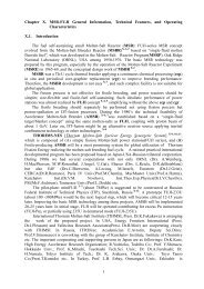
INTRODUCTION – <strong>SMART</strong> Plant<br />
Core<br />
17x17 rectangular arrays <strong>of</strong> Korea Optimized Fuel Assembly<br />
Soluble boron free operation with large negative MTC<br />
Long cycle operation with a s<strong>in</strong>gle batch reload scheme<br />
Steam Generator<br />
12 steam generator cassettes located between Rv and barrel<br />
Primary coolant flows <strong>the</strong> shell side and secondary fluid flows tube side<br />
Reduce <strong>the</strong> possibility <strong>of</strong> <strong>the</strong> SGTR accident<br />
Pressurizer<br />
Self controlled <strong>in</strong>-vessel pressurizer located <strong>in</strong> <strong>the</strong> upper space <strong>of</strong> Rv<br />
Annular cavity, <strong>in</strong>termediate cavity, and end cavity<br />
Control <strong>the</strong> pressure by a partial pressure <strong>of</strong> <strong>the</strong> non-condensable gas<br />
Elim<strong>in</strong>ate <strong>the</strong> active system such as spray and heater<br />
KAERI 5
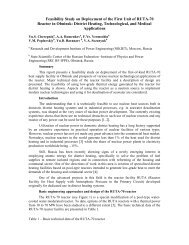
INTRODUCTION – <strong>SMART</strong>-P Plant<br />
Makeup System(x2)<br />
Emergency<br />
Boron<br />
Injection<br />
Tank<br />
Makeup<br />
Tank<br />
ECCS(x2)<br />
PRHRS(x4)<br />
ECT<br />
CT<br />
Makeup<br />
Pump<br />
ECC Tank<br />
Gas Cyl<strong>in</strong>der<br />
PSV<br />
V1<br />
V2<br />
MSIV<br />
Steam L<strong>in</strong>e<br />
Purification<br />
System<br />
Chemical<br />
Addition Tank<br />
PZR<br />
MCP S/G<br />
MFIV<br />
Feedwater<br />
L<strong>in</strong>e<br />
CORE<br />
PZR<br />
MCP<br />
(x4)<br />
CEDM<br />
(x49)<br />
IST<br />
Sampl<strong>in</strong>g System<br />
Purification Pump<br />
Reactor Coolant System<br />
Component<br />
Cool<strong>in</strong>g System<br />
KAERI 6
INTRODUCTION – <strong>SMART</strong> Plant<br />
<strong>Natural</strong> circulation circuit <strong>in</strong> <strong>the</strong> <strong>SMART</strong> Plant<br />
Three natural circulation circuit are <strong>in</strong>volved <strong>in</strong> <strong>the</strong> PRHRS operation<br />
• Reactor coolant system<br />
• Passive residual heat removal system<br />
• Emergency cooldown tank<br />
Passive residual heat removal system is designed to remove <strong>the</strong> decay heat<br />
• The system can remove <strong>the</strong> decay heat for 72 hours without operator action<br />
Emergency cooldown tank is a f<strong>in</strong>al heat s<strong>in</strong>k for <strong>the</strong> decay heat<br />
• The heat exchanger is submerged <strong>the</strong> water <strong>in</strong> <strong>the</strong> ECT<br />
KAERI 7
<strong>Natural</strong> <strong>Circulation</strong> <strong>of</strong> <strong>the</strong> <strong>SMART</strong><br />
<strong>Description</strong> <strong>of</strong> <strong>the</strong> reactor coolant system<br />
System<br />
• Consist <strong>of</strong> core, upper guide structure, MCP, SG primary<br />
side, downcomer<br />
Initiation <strong>of</strong> natural circulation <strong>in</strong> <strong>the</strong> RCS<br />
• MCP trip signal is <strong>in</strong>itiated by <strong>the</strong> LOOP signal or<br />
operator action manually<br />
Characteristics<br />
• <strong>the</strong> <strong>SMART</strong> can operate 25% <strong>of</strong> nom<strong>in</strong>al power by<br />
natural circulation operation mode<br />
• <strong>Natural</strong> circulation is established by hydraulic head and<br />
density difference between <strong>the</strong> core and <strong>the</strong> SG<br />
• Heat generated <strong>in</strong> <strong>the</strong> core is transported to <strong>the</strong> SG by<br />
natural circulation flow<br />
KAERI 8
<strong>Natural</strong> <strong>Circulation</strong> <strong>of</strong> <strong>the</strong> <strong>SMART</strong><br />
<strong>Description</strong> <strong>of</strong> <strong>the</strong> passive residual heat removal<br />
system<br />
Emergency<br />
Cooldown Tank<br />
System<br />
• Consist <strong>of</strong> SG secondary side, ma<strong>in</strong> steam pipe, PRHR<br />
steam l<strong>in</strong>e, Hx, PRHR liquid l<strong>in</strong>e, feedwater pipe and CT<br />
MSIV<br />
Steam<br />
discharge<br />
Initiation <strong>of</strong> natural circulation <strong>in</strong> <strong>the</strong> PRHRS<br />
• PRHRS actuation signal is <strong>in</strong>itiated by low FW flow, low<br />
SG pressure, high SG pressure, and manual<br />
Compensat<strong>in</strong>g<br />
Tank<br />
MFIV<br />
Feedwater<br />
supply<br />
SG<br />
Helical<br />
Tube<br />
Characteristics<br />
• <strong>Natural</strong> circulation is established by hydraulic head and<br />
density difference between <strong>the</strong> SG and <strong>the</strong> Hx<br />
• Heat transferred from <strong>the</strong> SG primary side is transported<br />
to <strong>the</strong> ECT by natural circulation flow<br />
• The ECT is located high enough relative to <strong>the</strong> SG<br />
• The CT is <strong>in</strong>stalled to make-up <strong>the</strong> <strong>in</strong>ventory <strong>in</strong> <strong>the</strong><br />
PRHRS at <strong>the</strong> beg<strong>in</strong>n<strong>in</strong>g <strong>of</strong> <strong>the</strong> transient<br />
KAERI 9
<strong>Natural</strong> <strong>Circulation</strong> <strong>of</strong> <strong>the</strong> <strong>SMART</strong><br />
<strong>Description</strong> <strong>of</strong> <strong>the</strong> Emergency cooldown tank<br />
System<br />
• Consist <strong>of</strong> <strong>the</strong> Hx shell side and fluid <strong>in</strong> <strong>the</strong> ECT<br />
Initiation <strong>of</strong> natural circulation <strong>in</strong> <strong>the</strong> ECT<br />
• The fluid <strong>in</strong> <strong>the</strong> ECT is circulated automatically<br />
when <strong>the</strong> heat transferred from <strong>the</strong> Hx<br />
Characteristics<br />
• The ECT is a big open tank filled with a water<br />
• The ECT is ultimate heat s<strong>in</strong>k<br />
• The ETC can operate at least 72 hours without<br />
any operator action when <strong>the</strong> reactor trips<br />
• <strong>Natural</strong> circulation loop is established locally by<br />
a density difference <strong>in</strong> <strong>the</strong> water column<br />
• Around top <strong>of</strong> <strong>the</strong> Hx is occurred a local boil<strong>in</strong>g<br />
KAERI 10
Conclusions<br />
The PRHRS provides an ultimate heat s<strong>in</strong>k when <strong>of</strong>f-site power is unavailable<br />
The reliability <strong>of</strong> <strong>the</strong> PRHRS is exam<strong>in</strong>ed at KAERI through VISTA facility<br />
The VISTA facility is an <strong>in</strong>tegral test facility simulat<strong>in</strong>g <strong>the</strong> reference plant<br />
The result <strong>of</strong> <strong>the</strong> VISTA experiment will present for <strong>the</strong> natural circulation flow<br />
KAERI 11