IMOS-Systemair
IMOS-Systemair
IMOS-Systemair

You also want an ePaper? Increase the reach of your titles
YUMPU automatically turns print PDFs into web optimized ePapers that Google loves.
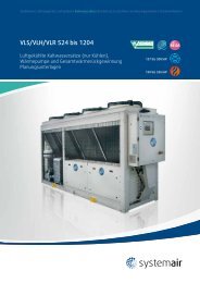
Fans | Air Handling Units | Air Distribution Products | Fire Safety | Air Curtains and Heating Products | Tunnel Fans<br />
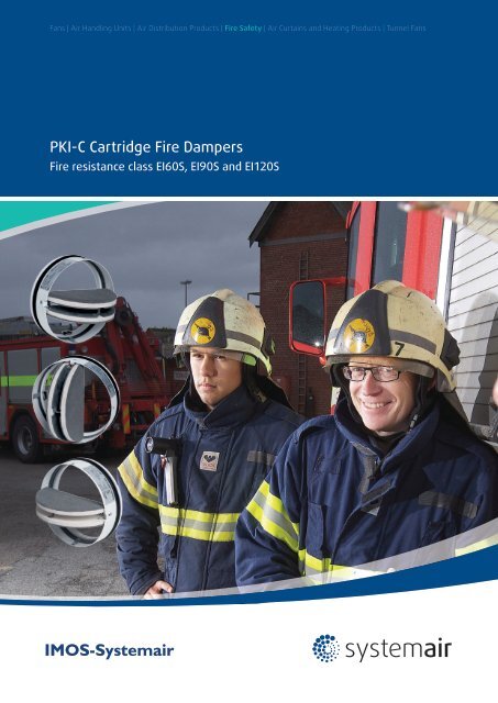
PKI-C Cartridge Fire Dampers<br />
Fire resistance class EI60S, EI90S and EI120S<br />
<strong>IMOS</strong>-<strong>Systemair</strong>
2 | Fire Safety Products<br />
PKI-C<br />
Cartridge Fire Dampers<br />
Cartridge dampers are designed in accordance with<br />
harmonized EN 15650 and certified to comply with<br />
the EI-S (EN 1366-2) performance attributes. PKI-C<br />
fire dampers are designed to be embedded into fire<br />
partition walls into transversal duct, or at the end of a<br />
duct in front of the valve. Installation of these devices is<br />
described in the Installation, Operation and Maintenance<br />
of the Cartridge Fire Dampers manual. As a standard,<br />
all the dampers are supplied in a basic version or with<br />
a microswitch, or accessories – cover plates, or with<br />
flexible duct coupling.<br />
The fire damper automatically sets itself to a „CLOSE“<br />
position if the thermal fuse link gets ruptured. After the<br />
closure, the damper blade is mechanically secured in<br />
the closed position and can only be opened manually,<br />
which requires access of the maintenance staff into the<br />
duct. To improve the duct accessibility for fire damper<br />
inspection purposes, we supply a flexible duct coupling<br />
as an accessory – labelled as TVKC in the Ordering Codes<br />
section. The thermal fuse link releases the coupling<br />
mechanism when the air temperature in the damper<br />
exceeds 72°C.<br />
Damper Installation, Operation<br />
and Maintenance<br />
The fire dampers should be installed, operated and<br />
maintained according to the Installation, Operation and<br />
Maintenance manual which is delivered with each PKI-C.<br />
Workplace Conditions<br />
The damper may be installed in the duct, in which<br />
the operating temperatures fall within the range of<br />
-10 to 65°C. The active fire-proof sealing must not be<br />
exposed to direct contact with water. The maximum air<br />
flow speed is 12m/s with purge air without mechanic<br />
or chemical contamination with uniform flow, without<br />
condensation, ice coating and ice. The device is not<br />
actuated until the ambient temperature reaches 65°C. In<br />
case of need of adjustment for higher temperatures in<br />
the workplace it is necessary to consult such demands<br />
with the producer and indicate them in the purchase<br />
order accordingly. In terms of their construction, the<br />
dampers are designed for use with a horizontal or a<br />
vertical blade axis.<br />
Transportation, Storage and<br />
Operating Conditions<br />
It is necessary to transport the dampers in boxes, by<br />
such means of transport that provide a cover. When<br />
handling during transportation and storage, the dampers<br />
must be protected against damage and weather<br />
conditions. The damper blades must be in the “CLOSE”<br />
position. It is recommended to store these products in a<br />
closed, dry area where the temperature falls within the<br />
range of -10°C to +50°C.<br />
The temperature during storage, transportation and<br />
operation must not exceed 65°C!<br />
Material Used and Disposal<br />
The product contains galvanized steel sheets, a calciumsilicate<br />
board, graphite fire-proof laminate, polyurethane<br />
foam, ethylene-propylene dry rubber, copper sheets,<br />
a special solder produced on a basis of Sn, Bi, Pb and<br />
powder paint. These are processed in compliance with<br />
the local regulations. The product does not contain any<br />
dangerous materials, with the exception of the solder’s<br />
miligram quantity that contains Pb.<br />
Warranty<br />
The manufacturer provides a 24-month warranty period<br />
starting on the date of expedition, provided that the<br />
transportation, manipulation and operating conditions<br />
are met.<br />
Appendix<br />
Any demands regarding deviations from the above<br />
mentioned technical specifications and conditions shall<br />
be discussed with the manufacturer. The manufacturer<br />
reserves the right to perform any modifications of<br />
the product without prior notice, provided that such<br />
changes have no effect on the quality and performance<br />
of the product. The most recent state of our products is<br />
available at www.imos-systemair.sk.
Fire Safety Products | 3<br />
Damper Codes and Types<br />
Ordering Code<br />
- Cover Plates<br />
Ordering Code - PKI-C<br />
Fire resistance class<br />
Dimensions<br />
Operation type<br />
PKI-C-EI -<br />
60S, 90S and 120S<br />
ød<br />
ZV through DV1<br />
PRC-ND<br />
NOTE: ND = Nominal dimension in table on page 4<br />
A complete set of four cover plates made of calciumsilicate<br />
boards (for usage during the installation please<br />
see the Installation, Operation and Maintenance manual).<br />
FOR DRY INSTALLATION COVERPLATES ARE OBLIGATORY!<br />
NOTE: E = Casing integrity, I = Thermal insulation, S = Smoke leakage<br />
ZV; Basic model with a spring return release driven by a<br />
thermal fuse link set to 72 °C.<br />
DV1; ZV + 230V end switch indicating the damper’s<br />
closed and open position<br />
Ordering Code<br />
- Flexible duct coupling<br />
TVKC-ND<br />
NOTE: ND = Nominal dimension in table on page 4<br />
A flexible coupling for easier accessibility during<br />
inspections is placed directly behind the built-in duct to a<br />
side where the damper blades open.<br />
PKI-C-EI60S, -EI90S and -EI120S<br />
We offer cartridge fire dampers with fire resistance class of 60, 90, 120 minutes for circular duct systems.<br />
The cartridge fire dampers fulfil EN 15650, have been tested in accordance with the EN 1366-2 regulation and<br />
classified in accordance with the EN13501-3 regulation:<br />
PKI-C EI60S-ZV through DV1<br />
For dimensions ø100 mm through ø200 mm<br />
Conformity certificate no.: 1396-CPD-0050<br />
Classification protocol no.: FIRES-CR-186-11-AUPE<br />
Test report no.:<br />
FIRES-FR-200-11-AUNE<br />
FIRES-FR-217-11-AUNE<br />
Installation:<br />
Solid wall – wet and dry<br />
Flexible wall – wet<br />
Ceiling – wet<br />
EI 60 (ve ho i ↔ o) S<br />
PKI-C EI90S-ZV through DV1<br />
For dimensions ø100 mm through ø200 mm<br />
Conformity certificate no.: 1396-CPD-0050<br />
Classification protocol no.: FIRES-CR-182-11-AUPE<br />
Test report no:<br />
FIRES-FR-180-11-AUNE<br />
FIRES-FR-199-11-AUNE<br />
Installation:<br />
Solid wall – wet and dry<br />
Flexible wall – wet and dry<br />
Ceiling – wet<br />
EI 90 (ve ho i ↔ o) S<br />
PKI-C EI120S-ZV through DV1<br />
For dimensions ø100 mm through ø200 mm<br />
Conformity certificate no.: 1396-CPD-0050<br />
Classification protocol no.: FIRES-CR-182-11-AUPE<br />
Test report no:<br />
FIRES-FR-180-11-AUNE<br />
FIRES-FR-199-11-AUNE<br />
Installation:<br />
Solid wall – wet and dry<br />
Flexible wall – wet and dry<br />
Ceiling – wet<br />
EI 120 (ve ho i ↔ o) S
4 | Fire Safety Products<br />
3<br />
Damper Parts Description:<br />
7<br />
1<br />
2<br />
4<br />
6<br />
1. Casing<br />
2. Damper blades<br />
3. External peripheral sealing<br />
4. Thermal fuse link<br />
5. Detent spring<br />
6. End switch 24 V DC / 230 V AC<br />
7. Internal peripheral sealing, expanding material<br />
5<br />
Fig. 1: Design and dimensions of the cartridge fire damper<br />
Main Dimensions and Weight<br />
ND d EI60/90/120S EI60S EI90/120S<br />
(mm) (mm) W1 (mm) M (kg)<br />
100<br />
27 0,3 0,3<br />
Ød<br />
125 39,5 0,4 0,4<br />
140 47 0,5 0,5<br />
150 ND-1,5 52 0,4 0,6<br />
160 57 0,5 0,6<br />
60 W1<br />
180 67 0,6 0,7<br />
200 77 0,7 0,9<br />
Connection of the End Switch<br />
CLOSED indicator<br />
OPEN indicator<br />
- black wire<br />
- blue wire<br />
- grey wire
Fire Safety Products | 5<br />
Adjustment of the Blades into the Operating Position<br />
1. Press both detent springs<br />
2. Open the blades into a parallel position<br />
3. Klick on the thermal fuse<br />
Pressure Loss and Noise<br />
100,0<br />
90<br />
80<br />
70<br />
60<br />
50<br />
40<br />
45 dB(A)<br />
30<br />
40 dB(A)<br />
20<br />
35 dB(A)<br />
Δp (Pa)<br />
10,0<br />
9<br />
8<br />
7<br />
6<br />
5<br />
4<br />
30 dB(A)<br />
3<br />
2<br />
1,0<br />
1<br />
2 3 4 5 6 7 8 9 10<br />
v (m/s)
6 | Fire Safety Products<br />
Installation<br />
Wall Installation<br />
1<br />
2<br />
3<br />
4<br />
5<br />
6<br />
1. wall<br />
2. duct<br />
3. installation plates<br />
4. mineral wool<br />
5. PKI-C<br />
6. gypsum / mortar /<br />
concrete<br />
7. disk valve<br />
7<br />
A B C<br />
A – dry installation using the cover plates into continuous ducts<br />
B – wet installation into continuous ducts<br />
C – installation into the end of a duct with a disk valve<br />
Ceiling Installation<br />
1<br />
2<br />
3<br />
4<br />
5<br />
1. ceiling<br />
2. duct<br />
3. gypsum / mortar /<br />
concrete<br />
4. PKI-C<br />
5. disk valve<br />
D<br />
E<br />
D – installation into continuous ducts<br />
E – installation with a disk valve orifice<br />
Installation Into the End of a Duct with a Valve<br />
It is possible to install the cartridge fire damper at the<br />
end of a duct in a wall / ceiling with a disc valve (it<br />
is needed to order the valve separately from the APD<br />
catalogue - suitable plastic air valve is “Balance-E” from<br />
<strong>Systemair</strong> AB, Sweden)<br />
Plasterboard wall EI60S EI90S EI120S<br />
H [mm] 100 125 150<br />
RF [mm] 12.5 12.5 12.5<br />
D1/ρ [mm/kg.m -3 ] 40/40 60/50 60/100<br />
MR PKI-C [mm] 100÷200 100÷200 100÷200<br />
1 2 3 4<br />
Plasterboard wall according to STN EN 1366-3<br />
1 - disc valve, 2 - PKI-C, 3 - gypsum, 4 - duct
Fire Safety Products | 7<br />
Technical Parameters<br />
Durability test - 50 cycles without a change to the required attributes<br />
Testing pressure - 300 Pa<br />
Safe position - Closed<br />
Possible installations - Vertical/horizontal, solid/flexible wall, wet/dry (see the certification and classification table)<br />
Airflow direction - Optional<br />
Side protected from fire - Optional<br />
Closure -<br />
By springs after the thermal fuse melts – 72 °C as standard, other options based after agreement with the<br />
manufacturer<br />
Ambient temperature - In case of a 72 °C thermal fuse, the temperature should be a maximum of 65 °C<br />
Repeated opening - It is possible to open the device manually when it is cold<br />
Closed/open indicator - 24 V DC / 230 V AC microswitch in version DV1<br />
Suitability for ambience - Inside only<br />
Inspection possibility - After installing the flexible coupling into an adjacent duct (see the PS option in the Ordering Codes section)<br />
Maintenance - Not needed
<strong>IMOS</strong>-<strong>Systemair</strong> 11/2011<br />
<strong>IMOS</strong>-<strong>Systemair</strong><br />
www.imos-systemair.sk<br />
www.systemair.com