Honda EU3000is Manual - Hollywood Studio Rentals
Honda EU3000is Manual - Hollywood Studio Rentals
Honda EU3000is Manual - Hollywood Studio Rentals

Create successful ePaper yourself
Turn your PDF publications into a flip-book with our unique Google optimized e-Paper software.
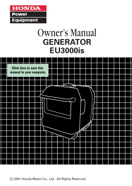
Owner’s <strong>Manual</strong><br />
GENERATOR<br />
<strong>EU3000is</strong><br />
o2001 <strong>Honda</strong> Motor Co., Ltd. -All Rights Reserved
The engine exhaust from this product<br />
contains chemicals known to the State<br />
of California to cause cancer, birth<br />
defects or other reproductive harm.<br />
The generator is a potential source of electrical shock if misused. Do<br />
not expose the generator to moisture, rain or snow. Do not let the<br />
generator get wet, and do not operate it with wet hands.<br />
Keep this owner’s manual handy, so you can refer to it at any time.<br />
This owner’s manual is considered a permanent part of the generator<br />
and should remain with the generator if resold.<br />
The information and specifications included in this publication were in<br />
effect at the time of approval for printing. <strong>Honda</strong> Motor Co., Ltd.<br />
reserves the right, however, to discontinue or change specifications or<br />
design at any time without notice and without incurring any obligation<br />
whatever. No part of this publication may be reproduced without<br />
written permission.
Congratulations on your selection of a <strong>Honda</strong> generator. We are<br />
certain you will be pleased with your purchase of one of the finest<br />
generators on the market.<br />
We want to help you get the best results from your new generator and<br />
to operate it safely. This manual contains the information on how to<br />
do that; please read it carefully.<br />
As you read this manual, you will find information preceded by a<br />
symbol. That information is intended to help you avoid<br />
damage to your generator, other property, or the environment.<br />
We suggest you read the Distributor’s Limited Warranty to fully<br />
understand its coverage and your responsibilities of ownership. The<br />
Distributor’s Limited Warranty is a separate document that should<br />
have been given to you by your dealer.<br />
When your generator needs scheduled maintenance, keep in mind<br />
that your <strong>Honda</strong> servicing dealer is specially trained in servicing<br />
<strong>Honda</strong> generators. Your authorized <strong>Honda</strong> servicing dealer is<br />
dedicated to your satisfaction and will be pleased to answer your<br />
questions and concerns.<br />
Best Wishes,<br />
<strong>Honda</strong> Motor Co., Ltd.<br />
1
A FEW WORDS ABOUT SAFETY<br />
Your safety and the safety of others are very important. And using<br />
this generator safely is an important responsibility.<br />
To help you make informed decisions about safety, we have provided<br />
operating procedures and other information on labels and in this<br />
manual. This information alerts you to potential hazards that could<br />
hurt you or others.<br />
Of course, it is not practical or possible to warn you about all the<br />
hazards associated with operating or maintaining a generator. You<br />
must use your own good judgement.<br />
You will find important safety information in a variety of forms,<br />
including:<br />
Safety Labels on the generator.<br />
Safety Messages preceded by a safety alert symbol and<br />
one of three signal words, DANGER, WARNING, or CAUTION.<br />
These signal words mean:<br />
You WILL be KILLED or SERIOUSLY HURT if<br />
you don’t follow instructions.<br />
You CAN be KILLED or SERIOUSLY HURT if<br />
you don’t follow instructions.<br />
You CAN be HURT if you don’t follow instructions.<br />
Safety Headings such as IMPORTANT SAFETY INFORMATION.<br />
Safety Section such as GENERATOR SAFETY.<br />
Instructions how to use this generator correctly and safely.<br />
This entire book is filled with important safety information please<br />
read it carefully.<br />
2
CONTENTS<br />
SAFETY ....................................................................................................... 5<br />
Safety Label Locations ........................................................................ 5<br />
Safety Information ............................................................................... 7<br />
COMPONENT IDENTIFICATION ............................................................... 9<br />
CONTROLS ............................................................................................... 11<br />
Engine Switch ..................................................................................... 11<br />
Recoil Starter ...................................................................................... 12<br />
Fuel Valve Lever ................................................................................. 12<br />
Choke Knob ........................................................................................ 13<br />
TM<br />
EcoThrottle Switch .......................................................................... 13<br />
Output Indicator Light ........................................................................ 14<br />
Overload Indicator Light .................................................................... 14<br />
Oil Alert System ............................................................................... 15<br />
Parallel Operation Outlets ................................................................. 15<br />
AC Circuit Protector ........................................................................... 16<br />
DC Receptacle ..................................................................................... 16<br />
DC Circuit Protector ........................................................................... 16<br />
Ground Terminal ................................................................................ 17<br />
GENERATOR USE .................................................................................... 18<br />
Connections to a Building Electrical System ................................... 18<br />
Ground System .................................................................................. 18<br />
Special Requirements ........................................................................ 19<br />
AC Applications .................................................................................. 20<br />
AC Operation ...................................................................................... 21<br />
AC Parallel Operation Applications .................................................. 23<br />
AC Parallel Operation ........................................................................ 25<br />
DC Operation ...................................................................................... 26<br />
Connecting the battery charging cable (optional equipment) ....... 26<br />
Disconnecting the battery charging cable ....................................... 28<br />
TM<br />
EcoThrottle System ......................................................................... 29<br />
High Altitude Operation ..................................................................... 30<br />
PRE-OPERATION CHECK ........................................................................ 31<br />
Engine Oil ........................................................................................... 31<br />
Refueling ............................................................................................. 32<br />
Fuel Recommendations ..................................................................... 33<br />
STARTING THE ENGINE ......................................................................... 35<br />
STOPPING THE ENGINE ......................................................................... 37<br />
3
MAINTENANCE ....................................................................................... 38<br />
The Importance of Maintenance ....................................................... 38<br />
Maintenance Safety ........................................................................... 39<br />
Emission Control System Information ............................................. 40<br />
Air Index .............................................................................................. 42<br />
Maintenance Schedule ...................................................................... 43<br />
Engine Oil Change ............................................................................. 44<br />
Air Cleaner Service ............................................................................ 45<br />
Spark Plug Service ............................................................................. 47<br />
Fuel Sediment Cup Cleaning ............................................................ 49<br />
Spark Arrester Maintenance ............................................................. 51<br />
Battery ................................................................................................. 54<br />
Fuse Replacement .............................................................................. 57<br />
TRANSPORTING/STORAGE ................................................................... 58<br />
Transporting ....................................................................................... 58<br />
Storage ................................................................................................ 59<br />
TROUBLESHOOTING .............................................................................. 61<br />
WIRING DIAGRAM .................................................................................. 63<br />
SPECIFICATIONS ..................................................................................... 64<br />
CUSTOMER SERVICE INFORMATION ................................................... 65<br />
INDEX ....................................................................................................... 66<br />
4
SAFETY<br />
SAFETY LABEL LOCATIONS<br />
These labels warn you of potential hazards that can cause serious<br />
injury. Read them carefully.<br />
If a label comes off or becomes hard to read, contact your <strong>Honda</strong><br />
generator dealer for a replacement.<br />
5
SAFETY INFORMATION<br />
<strong>Honda</strong> generators are designed to give safe and dependable service if<br />
operated according to instructions. Read and understand this owner’s<br />
manual before operating your generator. You can help prevent<br />
accidents by being familiar with your generator’s controls, and by<br />
observing safe operating procedures.<br />
Operator Responsibility<br />
Know how to stop the generator quickly in case of emergency.<br />
Understand the use of all generator controls, output receptacles,<br />
and connections.<br />
Be sure that anyone who operates the generator receives proper<br />
instruction. Do not let children operate the generator without<br />
parental supervision.<br />
Carbon Monoxide Hazards<br />
Exhaust contains poisonous carbon monoxide, a colorless and<br />
odorless gas. Breathing exhaust can cause loss of consciousness<br />
and may lead to death.<br />
If you run the generator in an area that is confined, or even partially<br />
enclosed, the air you breathe could contain a dangerous amount of<br />
exhaust gas. To keep exhaust gas from accumulating, provide<br />
adequate ventilation.<br />
7
Electric Shock Hazards<br />
The generator produces enough electric power to cause a serious<br />
shock or electrocution if misused.<br />
Fire and Burn Hazards<br />
The exhaust system gets hot enough to ignite some materials.<br />
Keep the generator at least 3 feet (1 meter) away from buildings<br />
and other equipment during operation.<br />
Do not enclose the generator in any structure.<br />
Keep flammable materials away from the generator.<br />
8<br />
Using a generator or electrical appliance in wet conditions, such as<br />
rain or snow, or near a pool or sprinkler system, or when your hands<br />
are wet, could result in electrocution. Keep the generator dry.<br />
If the generator is stored outdoors, unprotected from the weather,<br />
check all of the electrical components on the control panel, before<br />
each use. Moisture or ice can cause a malfunction or short circuit in<br />
electrical components which could result in electrocution.<br />
Do not connect to a building electrical system unless an isolation<br />
switch has been installed by a qualified electrician.<br />
Use only a <strong>Honda</strong> approved parallel operation kit (optional<br />
equipment) when connecting two <strong>EU3000is</strong> generators for parallel<br />
operation.<br />
Never connect different generator models and types.<br />
The muffler becomes very hot during operation and remains hot for<br />
a while after stopping the engine. Be careful not to touch the muffler<br />
while it is hot. Let the engine cool before storing the generator<br />
indoors.<br />
Gasoline is extremely flammable and is explosive under certain<br />
conditions. Do not smoke or allow flames or sparks where the<br />
generator is refueled or where gasoline is stored. Refuel in a wellventilated<br />
area with the engine stopped.<br />
Fuel vapors are extremely flammable and may ignite after the<br />
engine has started. Make sure that any spilled fuel has been wiped<br />
up before starting the generator.
COMPONENT IDENTIFICATION<br />
OUTPUT<br />
INDICATOR<br />
LIGHT<br />
OVERLOAD<br />
INDICATOR<br />
LIGHT<br />
OIL ALERT<br />
INDICATOR<br />
LIGHT<br />
PARALLEL OPERATION<br />
OUTLETS<br />
DC CIRCUIT<br />
PROTECTOR<br />
DC RECEPTACLE<br />
AC CIRCUIT<br />
PROTECTOR<br />
ENGINE SWITCH<br />
CHOKE KNOB<br />
FUEL VALVE LEVER<br />
AC RECEPTACLES<br />
ECOTHROTTLE<br />
TM<br />
SWITCH<br />
STAND TYPE<br />
WHEEL TYPE<br />
9
SPARK PLUG CAP<br />
MUFFLER<br />
FRONT HANDLE<br />
OIL FILLER CAP/<br />
DIPSTICK<br />
OIL DRAIN PLUG<br />
AIR CLEANER<br />
OIL MAINTENANCE COVER<br />
LEFT-SIDE MAINTENANCE COVER<br />
FRAME SERIAL NUMBER<br />
FUEL TANK CAP<br />
STARTER GRIP<br />
REAR HANDLE<br />
GROUND TERMINAL<br />
Record the frame serial number for your future reference. Refer to this<br />
serial number when ordering parts, and when making technical or<br />
warranty inquiries (see page 65 ).<br />
Frame serial number:<br />
Date purchased:<br />
10
CONTROLS<br />
ENGINE SWITCH<br />
To start and stop the engine.<br />
Key position:<br />
OFF:<br />
ON:<br />
START:<br />
To stop the engine. Key can be removed/inserted.<br />
To run the engine after starting.<br />
To start the engine by operating the starter motor.<br />
OFF<br />
ON<br />
START<br />
ENGINE SWITCH<br />
Return the key to the ON position once the engine has started. Do not<br />
use the starter for more than 5 seconds at a time. If the engine fails to<br />
start, release the switch and wait 10 seconds before operating the<br />
starter again.<br />
11
RECOIL STARTER<br />
To start the engine, pull the starter grip lightly until resistance is felt,<br />
then pull briskly.<br />
Do not allow the starter grip to snap back against the engine. Return it<br />
gently to prevent damage to the starter.<br />
STARTER GRIP<br />
FUEL VALVE LEVER<br />
The fuel valve is located on the control panel. When the fuel valve<br />
lever is in the ON position, fuel is allowed to flow from the fuel tank to<br />
the carburetor. Be sure to return the fuel valve lever to the OFF<br />
position after stopping the engine.<br />
ON<br />
OFF<br />
12<br />
FUEL VALVE LEVER
CHOKE KNOB<br />
The choke knob opens and closes the choke valve in the carburetor.<br />
Pulling the choke knob to the CLOSED position enriches the fuel<br />
mixture for starting a cold engine.<br />
Pushing the choke knob to the OPEN position provides the correct fuel<br />
mixture for operation after starting, and for restarting a warm engine.<br />
CHOKE KNOB<br />
CLOSED<br />
OPEN<br />
ECOTHROTTLE<br />
TM<br />
SWITCH<br />
TM<br />
The EcoThrottle system automatically reduces engine speed when<br />
all loads are turned off or disconnected. When appliances are turned<br />
on or reconnected, the engine returns to the proper speed to power<br />
the electrical load.<br />
If high electrical loads are connected simultaneously, turn the<br />
TM<br />
EcoThrottle switch to the OFF position to reduce voltage changes.<br />
ON:<br />
OFF:<br />
Recommended to minimize fuel consumption and further<br />
reduce noise levels when no load is applied to the<br />
generator.<br />
TM<br />
The EcoThrottle system does not operate.<br />
ECOTHROTTLE<br />
TM<br />
SWITCH<br />
ON<br />
OFF<br />
13
OUTPUT INDICATOR LIGHT<br />
The output indicator light (green) is illuminated when the generator is<br />
operating normally. It indicates that the generator is producing<br />
electrical power at the receptacles.<br />
OUTPUT<br />
INDICATOR<br />
LIGHT (GREEN)<br />
OVERLOAD INDICATOR LIGHT<br />
If the generator is overloaded (see page 64),<br />
or if there is a short circuit<br />
in a connected appliance, or if the inverter is overheated, the overload<br />
indicator light (red) will go ON. The overload indicator light (red) will<br />
stay ON, and after about four seconds, current to the connected<br />
appliance(s) will shut off, and the output indicator light (green) will go<br />
OFF.<br />
OVERLOAD<br />
INDICATOR<br />
LIGHT (RED)<br />
14
OIL ALERT<br />
SYSTEM<br />
The Oil Alert system is designed to prevent engine damage caused<br />
by an insufficient amount of oil in the crankcase. Before the oil level in<br />
the crankcase can fall below a safe limit, the Oil Alert indicator light<br />
comes on and the Oil Alert system will automatically stop the engine<br />
(the engine switch will remain in the ON position).<br />
If the engine stops or the Oil Alert indicator light comes on when you<br />
turn the engine switch to START or pull the starter grip, check the<br />
engine oil level (see page 31 ) before troubleshooting in other areas.<br />
OIL ALERT<br />
INDICATOR<br />
LIGHT<br />
PARALLEL OPERATION OUTLETS<br />
These outlets are used for connecting two <strong>EU3000is</strong> generators for<br />
parallel operation (see page 25).<br />
A <strong>Honda</strong> approved parallel operation<br />
kit (optional equipment) is required for parallel operation. This kit can<br />
be purchased from an authorized <strong>Honda</strong> generator dealer.<br />
PARALLEL OPERATION<br />
OUTLETS<br />
15
AC CIRCUIT PROTECTOR<br />
The AC circuit protectors will automatically switch OFF if there is a<br />
short circuit or a significant overload of the generator at the 120V 20A<br />
locking plug, or 120V 30A locking plug receptacle. If an AC circuit<br />
protector switches OFF automatically, check that the appliance is<br />
working properly and does not exceed the rated load capacity of the<br />
circuit before resetting the AC circuit protector ON.<br />
AC CIRCUIT PROTECTOR<br />
for Receptacle<br />
AC CIRCUIT PROTECTOR<br />
120V 20A<br />
AC CIRCUIT PROTECTOR<br />
for Receptacle<br />
ON<br />
120V 30A<br />
OFF<br />
PUSH<br />
DC RECEPTACLE<br />
The DC receptacle should ONLY be used for charging 12-volt<br />
automotive type batteries.<br />
DC CIRCUIT PROTECTOR<br />
The DC circuit protector automatically shuts off the DC battery<br />
charging circuit when the DC charging circuit is overloaded, when<br />
there is a problem with the battery, or when the connections between<br />
the battery and the generator are improper.<br />
DC CIRCUIT<br />
PROTECTOR<br />
OFF<br />
ON<br />
PUSH<br />
DC RECEPTACLE<br />
16
GROUND TERMINAL<br />
The generator ground terminal is connected to the frame of the<br />
generator, the metal non-current-carrying parts of the generator, and<br />
the ground terminals of each receptacle.<br />
Before using the ground terminal, consult a qualified electrician,<br />
electrical inspector or local agency having jurisdiction for local codes<br />
or ordinances that apply to the intended use of the generator.<br />
GROUND TERMINAL<br />
17
GENERATOR USE<br />
CONNECTIONS TO A BUILDING ELECTRICAL SYSTEM<br />
Connections for standby power to a building electrical system must be<br />
made by a qualified electrician. The connection must isolate the<br />
generator power from utility power, and must comply with all<br />
applicable laws and electrical codes. A transfer switch, which isolates<br />
generator power from utility power, is available through authorized<br />
<strong>Honda</strong> generator dealers.<br />
Improper connections to a building electrical system can allow<br />
electrical current from the generator to backfeed into the utility lines.<br />
Such backfeed may electrocute utility company workers or others<br />
who contact the lines during a power outage, and the generator may<br />
explode, burn, or cause fires when utility power is restored. Consult<br />
the utility company or a qualified electrician.<br />
GROUND SYSTEM<br />
<strong>Honda</strong> portable generators have a system ground that connects<br />
generator frame components to the ground terminals in the AC output<br />
receptacles. The system ground is not connected to the AC neutral<br />
wire. If the generator is tested by a receptacle tester, it will not show<br />
the same ground circuit condition as for a home receptacle.<br />
18
SPECIAL REQUIREMENTS<br />
Keep all cooling holes open and not blocked by debris, mud, water, etc.<br />
Cooling holes are located on the side panel, the control panel, and the<br />
bottom of the generator. If the cooling holes are blocked, the<br />
generator may overheat and damage the engine, inverter, or windings.<br />
Do not lay the generator on its side when moving, storing, or<br />
operating it. Oil may leak and damage the engine or your property.<br />
There may be Federal or State Occupational Safety and Health<br />
Administration (OSHA) regulations, local codes, or ordinances that<br />
apply to the intended use of the generator. Please consult a qualified<br />
electrician, electrical inspector, or the local agency having jurisdiction.<br />
In some areas, generators are required to be registered with local<br />
utility companies.<br />
If the generator is used at a construction site, there may be<br />
additional regulations which must be observed.<br />
19
AC APPLICATIONS<br />
Before connecting an appliance or power cord to the generator:<br />
Make sure that it is in good working order. Faulty appliances or<br />
power cords can create a potential for electrical shock.<br />
If an appliance begins to operate abnormally, becomes sluggish or<br />
stops suddenly, turn it off immediately. Disconnect the appliance,<br />
and determine whether the problem is the appliance, or if the rated<br />
load capacity of the generator has been exceeded.<br />
Make sure that the electrical rating of the tool or appliance does not<br />
exceed that of the generator. Never exceed the maximum power<br />
rating of the generator. Power levels between rated and maximum<br />
may be used for no more than 30 minutes.<br />
Substantial overloading that continuously lights the overload indicator<br />
light (red) may damage the generator. Marginal overloading that<br />
temporarily lights the overload indicator light (red) may shorten the<br />
service life of the generator.<br />
Limit operation requiring maximum power to 30 minutes.<br />
Maximum power is:<br />
3.0 kVA<br />
For continuous operation, do not exceed the rated power.<br />
Rated power is:<br />
2.8 kVA<br />
The total power requirements (VA) of all appliances connected must<br />
be considered. Appliance and power tool manufacturers usually list<br />
rating information near the model number or serial number.<br />
20
AC OPERATION<br />
1. Start the engine and make sure the output indicator light (green)<br />
comes on (see page35 and 36 ).<br />
2. Plug in the appliance.<br />
Most motorized appliances require more than their rated wattage for<br />
startup.<br />
OUTPUT<br />
INDICATOR<br />
LIGHT (GREEN)<br />
PLUG<br />
OVERLOAD<br />
INDICATOR<br />
LIGHT (RED)<br />
If the generator is overloaded (see page 19 ), or if there is a short circuit<br />
in a connected appliance, or if the inverter is overheated, the overload<br />
indicator light (red) will come ON. The overload indicator light (red)<br />
will stay ON, and after about five seconds, current to the connected<br />
appliance(s) will shut off, and the output indicator light (green) will go<br />
OFF. Stop the engine and investigate the problem.<br />
Determine if the cause is a short circuit in a connected appliance, an<br />
overload, or an overheated inverter. Correct the problem and restart<br />
the generator.<br />
Before connecting an appliance to the generator, make sure that it is in<br />
good order and that its electrical rating does not exceed that of the<br />
generator. Then start the generator and connect the appliance power<br />
cord.<br />
21
When an electric motor is started, the overload indicator light (red)<br />
may come on. This is normal if the overload indicator light (red) goes<br />
off after about four (4) seconds. If the overload indicator light (red)<br />
stays on, consult your <strong>Honda</strong> generator dealer.<br />
22
AC PARALLEL OPERATION APPLICATIONS<br />
Before connecting an appliance or power cord to the generator:<br />
Make sure that it is in good working order. Faulty appliances or<br />
power cords can create a potential for electrical shock.<br />
If an appliance begins to operate abnormally, becomes sluggish or<br />
stops suddenly, turn it off immediately. Disconnect the appliance,<br />
and determine whether the problem is the appliance, or if the rated<br />
load capacity of the generator has been exceeded.<br />
Make sure that the electrical rating of the tool or appliance does not<br />
exceed that of the generator. Never exceed the maximum power<br />
rating of the generator. Power levels between rated and maximum<br />
may be used for no more than 30 minutes.<br />
Never connect different generator models and types.<br />
Use only a <strong>Honda</strong> approved parallel operation kit (optional<br />
equipment) when connecting two <strong>EU3000is</strong> generators for parallel<br />
operation.<br />
Never connect or remove the parallel operation kit when the<br />
generator is running.<br />
For single generator operation, the parallel operation kit must be<br />
removed.<br />
Substantial overloading that continuously lights the overload indicator<br />
light (red) may damage the generator. Marginal overloading that<br />
temporarily lights the overload indicator light (red) may shorten the<br />
service life of the generator.<br />
23
For continuous operation, do not exceed the rated power.<br />
Rated power in parallel operation is:<br />
5.6 kVA<br />
The total power requirements (VA) of all appliances connected must<br />
be considered. Appliance and power tool manufacturers usually list<br />
rating information near the model number or serial number.<br />
24
AC PARALLEL OPERATION<br />
1. Connect the parallel operation kit between the two <strong>EU3000is</strong><br />
generators following the instructions supplied with the kit.<br />
PARALLEL OPERATION KIT<br />
(optional equipment)<br />
2. Start the generators and make sure the output indicator lights<br />
(green) come on (see pages 35and 36).<br />
3. Plug in the appliance following the instructions provided with the<br />
parallel operation kit.<br />
Most motorized appliances require more than their rated wattage for<br />
startup.<br />
If the generators are overloaded (see page 24 ), or if there is a short<br />
circuit in a connected appliance, the overload indicator lights (red)<br />
will go ON. The overload indicator lights (red) will stay ON, and after<br />
about four seconds, current to the connected appliance(s) will shut<br />
off, and the output indicator lights (green) will go OFF. Stop the<br />
engines and investigate the problem.<br />
25
DC OPERATION<br />
The DC receptacle should ONLY be used for charging 12-volt<br />
automotive type batteries.<br />
TM<br />
DC output will vary according to the position of the EcoThrottle<br />
TM<br />
switch. When the EcoThrottle switch is turned to the ON position and<br />
the AC output is not used, the DC current will be about one-third of the<br />
rated current.<br />
DC Current<br />
EcoThrottle<br />
Model<br />
<strong>EU3000is</strong><br />
TM<br />
switch<br />
OFF<br />
12 A<br />
ON<br />
(Do not use the AC output)<br />
approximately 4 A<br />
Connecting the battery charging cable (optional equipment):<br />
1. Before connecting the battery charging cable to a battery that is<br />
installed in a vehicle, disconnect the vehicle battery ground cable<br />
from the negative ( ) battery terminal.<br />
A battery can explode if you do not follow the correct procedure,<br />
seriously injuring anyone nearby.<br />
Keep all sparks, open flames, and smoking materials away from the<br />
battery.<br />
26
2. Plug the battery charging cable into the DC receptacle of the<br />
generator.<br />
3. Connect the red lead of the battery charging cable to the positive<br />
( ) battery terminal and the black lead to the negative ( ) battery<br />
terminal.<br />
YELLOW INDICATOR<br />
OFF<br />
ON<br />
DC RECEPTACLE<br />
DC CIRCUIT PROTECTOR<br />
BATTERY CHARGING CABLE<br />
(optional equipment)<br />
RED LEAD<br />
BLACK LEAD<br />
27
4. Start the generator.<br />
Do not start the vehicle while the battery charging cable is connected<br />
and the generator is running. The vehicle or the generator may be<br />
damaged.<br />
An overloaded DC circuit, excessive current drawn by the battery, or a<br />
wiring problem will trip the DC circuit protector (the yellow indicator<br />
inside the clear circuit protector button will pop out). If this happens,<br />
wait a few minutes before pushing in the circuit protector button to<br />
resume operation. If the circuit protector continues to go OFF,<br />
discontinue charging and see your authorized <strong>Honda</strong> generator dealer.<br />
Disconnecting the battery charging cable:<br />
1. Stop the engine.<br />
2. Disconnect the black lead of the battery charging cable from the<br />
negative ( ) battery terminal.<br />
3. Disconnect the red lead of the battery charging cable from the<br />
positive ( ) battery terminal.<br />
4. Disconnect the battery charging cable from the DC receptacle of the<br />
generator.<br />
5. Connect the vehicle battery ground cable to the negative ( ) battery<br />
terminal.<br />
BATTERY CHARGING CABLE<br />
(optional equipment)<br />
RED LEAD<br />
BLACK LEAD<br />
28
ECOTHROTTLE<br />
TM<br />
SYSTEM<br />
With the switch in the ON position, engine speed is automatically<br />
lowered when loads are reduced, turned OFF or disconnected. When<br />
appliances are turned ON or reconnected, the engine returns to the<br />
proper speed to power the electrical load. In the OFF position, the<br />
TM<br />
EcoThrottle system does not operate.<br />
Appliances with large start-up power demands may not allow the<br />
engine to reach normal operating rpm when they are connected to the<br />
TM<br />
generator. Turn the EcoThrottle to the OFF position and connect the<br />
appliance to the generator. If the engine still will not reach normal<br />
operating speed, check that the appliance does not exceed the rated<br />
load capacity of the generator.<br />
If high electrical loads are connected simultaneously, turn the<br />
TM<br />
EcoThrottle switch to the OFF position to reduce voltage changes.<br />
TM<br />
The EcoThrottle system is not effective for use with appliances that<br />
require only momentary power. If the tool or appliance will be turned<br />
TM<br />
ON and OFF quickly, the EcoThrottle switch should be in the OFF<br />
position.<br />
ECOTHROTTLE<br />
TM<br />
SWITCH<br />
ON<br />
OFF<br />
29
HIGH ALTITUDE OPERATION<br />
At high altitude, the standard carburetor air/fuel mixture will be too<br />
rich. Performance will decrease, and fuel consumption will increase. A<br />
very rich mixture will also foul the spark plug and cause hard starting.<br />
Operation at an altitude that differs from that at which this engine was<br />
certified, for extended periods of time, may increase emissions.<br />
High altitude performance can be improved by specific modifications<br />
to the carburetor. If you always operate your generator at altitudes<br />
above 5,000 feet (1,500 meters), have your servicing dealer perform<br />
this carburetor modification. This engine, when operated at high<br />
altitude with the carburetor modifications for high altitude use, will<br />
meet each emission standard throughout its useful life.<br />
Even with carburetor modification, engine horsepower will decrease<br />
about 3.5% for each 1,000-foot (300-meter) increase in altitude. The effect<br />
of altitude on horsepower will be greater than this if no carburetor<br />
modification is made.<br />
When the carburetor has been modified for high altitude operation,<br />
the air/fuel mixture will be too lean for low altitude use. Operation at<br />
altitudes below 5,000 feet (1,500 meters) with a modified carburetor<br />
may cause the engine to overheat and result in serious engine damage.<br />
For use at low altitudes, have your servicing dealer return the<br />
carburetor to original factory specifications.<br />
30
PRE-OPERATION CHECK<br />
ENGINE OIL<br />
Engine oil is a major factor affecting engine performance and service<br />
life. Non detergent and 2-stroke engine oils will damage the engine<br />
and are not recommended.<br />
Check the oil level BEFORE EACH<br />
USE with the generator on a level<br />
surface and the engine stopped.<br />
Use 4-stroke motor oil that meets<br />
or exceeds the requirements for<br />
API service classification SJ. Always<br />
check the API SERVICE label<br />
on the oil container to be sure it includes<br />
the letter SJ or higher.<br />
DIPSTICK<br />
UPPER LIMIT<br />
SAE Viscosity Grades<br />
AMBIENT TEMPERATURE<br />
SAE 10W-30 is recommended for general, all-temperature use. Other<br />
viscosities shown in the chart may be used when the average<br />
temperature in your area is within the indicated range.<br />
1. Open the oil maintenance cover.<br />
2. Remove the oil filler cap and wipe the dipstick clean.<br />
3. Check the oil level by inserting the dipstick into the filler neck<br />
without screwing it in.<br />
4. If the level is low, fill to the top of the oil filler neck with the<br />
recommended oil.<br />
5. Close and latch the oil maintenance cover.<br />
OIL FILLER CAP<br />
31
REFUELING<br />
Fuel tank capacity: 3.43 US gal (13.0 )<br />
With the engine stopped, check the fuel level gauge. Refill the fuel tank<br />
if the fuel level is low.<br />
Gasoline is highly flammable and explosive.<br />
You can be burned or seriously injured when handling fuel.<br />
Stop the engine and keep heat, sparks, and flame away.<br />
Handle fuel only outdoors.<br />
Wipe up spills immediately.<br />
Refuel in a well-ventillated area with the engine stopped. If the engine<br />
has been running, allow it to cool first. Refuel carefully to avoid<br />
spilling fuel. Do not fill above the fuel strainer shoulder. After refueling,<br />
tighten the fuel tank cap securely.<br />
Never refuel the engine inside a building where gasoline fumes may<br />
reach flames or sparks. Keep gasoline away from appliance pilot lights,<br />
barbecues, electric appliances, power tools, etc.<br />
Spilled fuel is not only a fire hazard, it causes environmental damage.<br />
Wipe up spills immediately.<br />
FUEL LEVEL GAUGE<br />
FULL<br />
EMPTY<br />
MAXIMUM FUEL LEVEL<br />
(FUEL STRAINER SHOULDER)<br />
32<br />
FUEL TANK CAP
FUEL RECOMMENDATIONS<br />
Use unleaded gasoline with a pump octane rating of 86 or higher.<br />
This engine is certified to operate on unleaded gasoline.<br />
Unleaded gasoline produces fewer engine and spark plug deposits<br />
and extends exhaust system life.<br />
Never use stale or contaminated gasoline or an oil/gasoline mixture.<br />
Avoid getting dirt or water in the fuel tank.<br />
Occasionally you may hear a light ‘‘spark knock’’ or ‘‘pinging’’<br />
(metallic rapping noise) while operating under heavy loads. This is no<br />
cause for concern.<br />
If spark knock or pinging occurs at a steady engine speed, under<br />
normal load, change brands of gasoline. If spark knock or pinging<br />
persists, see an authorized <strong>Honda</strong> generator dealer.<br />
Running the engine with persistent spark knock or pinging can cause<br />
engine damage.<br />
Running the engine with persistent spark knock or pinging is misuse,<br />
and the Distributor’s Limited Warranty does not cover parts damaged<br />
by misuse.<br />
33
Oxygenated Fuels<br />
Some conventional gasolines are being blended with alcohol or an<br />
ether compound. These gasolines are collectively referred to as<br />
oxygenated fuels. To meet clean air standards, some areas of the<br />
United States and Canada use oxygenated fuels to help reduce<br />
emissions.<br />
If you use an oxygenated fuel, be sure it is unleaded and meets the<br />
minimum octane rating requirement.<br />
Before using an oxygenated fuel, try to confirm the fuel’s contents.<br />
Some states/provinces require this information to be posted on the<br />
pump.<br />
The following are the EPA approved percentages of oxygenates:<br />
ETHANOL<br />
MTBE<br />
METHANOL<br />
(ethyl or grain alcohol) 10% by volume<br />
You may use gasoline containing up to 10% ethanol<br />
by volume. Gasoline containing ethanol may be<br />
marketed under the name Gasohol.<br />
(methyl tertiary butyl ether) 15% by volume<br />
You may use gasoline containing up to 15% MTBE<br />
by volume.<br />
(methyl or wood alcohol) 5% by volume<br />
You may use gasoline containing up to 5%<br />
methanol by volume as long as it also contains<br />
cosolvents and corrosion inhibitors to protect the<br />
fuel system. Gasoline containing more than 5%<br />
methanol by volume may cause starting and/or<br />
performance problems. It may also damage metal,<br />
rubber, and plastic parts of your fuel system.<br />
If you notice any undesirable operating symptoms, try another service<br />
station or switch to another brand of gasoline.<br />
Fuel system damage or performance problems resulting from the use<br />
of an oxygenated fuel containing more than the percentages of<br />
oxygenates mentioned above are not covered under the Distributor’s<br />
Limited Warranty.<br />
34
STARTING THE ENGINE<br />
Electric starting:<br />
1. Make sure that all appliances are disconnected from the AC<br />
receptacles.<br />
2. Turn the fuel valve lever to the ON position.<br />
3. To start a cold engine, pull the choke knob out to the CLOSED<br />
position.<br />
To restart a warm engine, leave the choke knob in the OPEN position.<br />
4. Turn the engine switch to the START position and hold it there for 5<br />
seconds or until the engine starts.<br />
Operating the starter motor for more than 5 seconds can damage<br />
the motor. If the engine fails to start, release the switch and wait 10<br />
seconds before operating the starter again.<br />
If the speed of the starter motor drops after a period of time, it is an<br />
indication that the battery should be recharged.<br />
When the engine starts, allow the engine switch to return to the ON<br />
position.<br />
5. If the choke knob was moved to the CLOSED position to start the<br />
engine, gradually push it to the OPEN position as the engine warms<br />
up.<br />
TM<br />
6. If you wish to use the EcoThrottle system, turn the EcoThrottle<br />
switch to the ON position after the engine has warmed up for 2 or 3<br />
minutes.<br />
TM<br />
35
<strong>Manual</strong> starting:<br />
1. Make sure that all appliances are disconnected from the AC<br />
receptacles.<br />
2. Turn the fuel valve lever to the ON position.<br />
3. To start a cold engine, pull the choke knob out to the CLOSED<br />
position.<br />
To restart a warm engine, leave the choke knob in the OPEN position.<br />
4. Turn the engine switch to the ON position.<br />
5. Pull the starter grip lightly until resistance is felt, then pull briskly.<br />
Do not allow the starter grip to snap back against the engine. Return it<br />
gently to prevent damage to the starter or housing.<br />
6. If the choke knob was moved to the CLOSED position to start the<br />
engine, gradually push it to the OPEN position as the engine warms<br />
up.<br />
TM<br />
7. If you wish to use the EcoThrottle system, turn the EcoThrottle<br />
switch to the ON position after the engine has warmed up for 2 or 3<br />
minutes.<br />
TM<br />
36
STOPPING THE ENGINE<br />
In an emergency:<br />
1. To stop the engine in an emergency, turn the engine switch to the<br />
OFF position.<br />
In normal use:<br />
1. Unplug appliances from the generator receptacles.<br />
If applicable for parallel operation, unplug the appliance from the<br />
parallel operation kit.<br />
2. Turn the engine switch to the OFF position.<br />
3. Turn the fuel valve lever to the OFF position.<br />
4. If two generators were connected for parallel operation, disconnect<br />
the parallel operation kit/receptacle assembly after stopping the<br />
engines if you do not wish to resume parallel operation.<br />
37
MAINTENANCE<br />
THE IMPORTANCE OF MAINTENANCE<br />
Good maintenance is essential for safe, economical, and troublefree<br />
operation. It will also help reduce air pollution.<br />
Improper maintenance, or failure to correct a problem before<br />
operation, can cause a malfunction in which you can be seriously<br />
hurt or killed.<br />
Always follow the inspection and maintenance recommendations<br />
and schedules in this owner’s manual.<br />
To help you properly care for your generator, the following pages<br />
include a maintenance schedule, routine inspection procedures, and<br />
simple maintenance procedures using basic hand tools. Other<br />
service tasks that are more difficult, or require special tools, are best<br />
handled by professionals and are normally performed by a <strong>Honda</strong><br />
technician or other qualified mechanic.<br />
The maintenance schedule applies to normal operating conditions.<br />
If you operate your generator under severe conditions, such as<br />
sustained high-load or high-temperature operation, or use it in<br />
unusually wet or dusty conditions, consult your servicing dealer for<br />
recommendations applicable to your individual needs and use.<br />
Maintenance, replacement, or repair of the emission control devices<br />
and systems may be performed by any engine repair establishment<br />
or individual, using parts that are ‘‘certified’’ to EPA standards.<br />
38
MAINTENANCE SAFETY<br />
Some of the most important safety precautions follow. However, we<br />
cannot warn you of every conceivable hazard that can arise in<br />
performing maintenance. Only you can decide whether or not you<br />
should perform a given task.<br />
Failure to properly follow maintenance instructions and precautions<br />
can cause you to be seriously hurt or killed.<br />
Always follow the procedures and precautions in the owner’s manual.<br />
Safety Precautions<br />
Make sure the engine is off before you begin any maintenance or<br />
repairs. This will eliminate several potential hazards:<br />
Carbon monoxide poisoning from engine exhaust.<br />
Be sure there is adequate ventilation whenever you operate the<br />
engine.<br />
Burns from hot parts.<br />
Let the engine and exhaust system cool before touching.<br />
Injury from moving parts.<br />
Do not run the engine unless instructed to do so.<br />
Read the instructions before you begin, and make sure you have the<br />
tools and skills required.<br />
To reduce the possibility of fire or explosion, be careful when<br />
working around gasoline. Use only a nonflammable solvent, not<br />
gasoline, to clean parts. Keep cigarettes, sparks, and flames away<br />
from all fuel-related parts.<br />
Remember that your servicing dealer knows your generator best and<br />
is fully equipped to maintain and repair it.<br />
To ensure the best quality and reliability, use only new, genuine<br />
<strong>Honda</strong> parts or their equivalents for repair or replacement.<br />
39
EMISSION CONTROL SYSTEM INFORMATION<br />
Source of Emissions<br />
The combustion process produces carbon monoxide, oxides of<br />
nitrogen, and hydrocarbons. Control of hydrocarbons and oxides of<br />
nitrogen are very important because, under certain conditions, they<br />
react to form photochemical smog when subjected to sunlight. Carbon<br />
monoxide does not react in the same way, but it is toxic.<br />
<strong>Honda</strong> utilizes lean carburetor settings and other systems to reduce<br />
the emissions of carbon monoxide, oxides of nitrogen, and<br />
hydrocarbons.<br />
The U.S. and California Clean Air Acts<br />
EPA and California regulations require all manufacturers to furnish<br />
written instructions describing the operation and maintenance of<br />
emission control systems.<br />
The following instructions and procedures must be followed in order<br />
to keep the emissions from your <strong>Honda</strong> engine within the emission<br />
standards.<br />
Tampering and Altering<br />
Tampering with or altering the emission control system may increase<br />
emissions beyond the legal limit. Among those acts that constitute<br />
tampering are:<br />
Removal or alteration of any part of the intake, fuel, or exhaust<br />
systems.<br />
Altering or defeating the governor linkage or speed-adjusting<br />
mechanism to cause the engine to operate outside its design<br />
parameters.<br />
40
Problems That May Affect Emissions<br />
If you are aware of any of the following symptoms, have your engine<br />
inspected and repaired by your servicing dealer.<br />
Hard starting or stalling after starting.<br />
Rough idle.<br />
Misfiring or backfiring under load.<br />
Afterburning (backfiring).<br />
Black exhaust smoke or high fuel consumption.<br />
Replacement Parts<br />
The emission control systems on your <strong>Honda</strong> engine were designed,<br />
built, and certified to conform with EPA and California emission<br />
regulations. We recommend the use of genuine <strong>Honda</strong> parts<br />
whenever you have maintenance done. These original-design<br />
replacement parts are manufactured to the same standards as the<br />
original parts, so you can be confident of their performance. The<br />
use of replacement parts that are not of the original design and<br />
quality may impair the effectiveness of your emission control<br />
system.<br />
A manufacturer of an aftermarket part assumes the responsibility<br />
that the part will not adversely affect emission performance. The<br />
manufacturer or rebuilder of the part must certify that use of the part<br />
will not result in a failure of the engine to comply with emission<br />
regulations.<br />
Maintenance<br />
Follow the maintenance schedule on page 43 . Remember that this<br />
schedule is based on the assumption that your machine will be used<br />
for its designed purpose. Sustained high-load or high-temperature<br />
operation, or use in unusually wet or dusty conditions, will require<br />
more frequent service.<br />
41
AIR INDEX<br />
An Air Index Information hang tag/label is applied to engines certified<br />
to an emission durability time period in accordance with the<br />
requirements of the California Air Resources Board.<br />
The bar graph is intended to provide you, our customer, the ability to<br />
compare the emissions performance of available engines. The lower<br />
the Air Index, the less pollution.<br />
The durability description is intended to provide you with information<br />
relating the engine’s emission durability period. The descriptive term<br />
indicates the usefullife period for the engine’s emission control system.<br />
See your Emission Control System Warranty for additional<br />
information.<br />
Descriptive Term<br />
Moderate<br />
Intermediate<br />
Extended<br />
Applicable to Emission Durability Period<br />
50 hours (0-65 cc)<br />
125 hours (greater than 65 cc)<br />
125 hours (0-65 cc)<br />
250 hours (greater than 65 cc)<br />
300 hours (0-65 cc)<br />
500 hours (greater than 65 cc)<br />
The Air Index Information hang tag must remain on the generator until<br />
it is sold. Remove the hang tag before operating the generator.<br />
42
MAINTENANCE SCHEDULE<br />
REGULAR SERVICE PERIOD (3)<br />
ITEM<br />
Perform at every indicated month<br />
or operating hour interval,<br />
whichever comes first.<br />
Engine oil<br />
Air filter<br />
Sediment cup<br />
Spark plug<br />
Spark arrester<br />
Valve clearance<br />
Combustion<br />
chamber<br />
Fuel tank and filter<br />
Fuel line<br />
Check level<br />
Change<br />
Check<br />
Clean<br />
Replace<br />
Clean<br />
Check-adjust<br />
Replace<br />
Clean<br />
Check-adjust<br />
Clean<br />
Each use<br />
First<br />
month<br />
or<br />
20 Hrs.<br />
Every<br />
3 months<br />
or<br />
50 Hrs.<br />
Replace the paper air filter only.<br />
(1) Service more frequently when used in dusty areas.<br />
(2) These items should be serviced by an authorized <strong>Honda</strong> generator dealer, unless the owner<br />
has the proper tools and is mechanically proficient. See the <strong>Honda</strong> Shop <strong>Manual</strong>.<br />
(3) For commercial use, log hours of operation to determine proper maintenance intervals.<br />
(1)<br />
Every<br />
6 months<br />
or<br />
100 Hrs.<br />
After every 500 Hrs. (2)<br />
Clean<br />
Check Every 2 years (Replace if necessary) (2)<br />
Every<br />
year<br />
or<br />
300 Hrs.<br />
<br />
(2)<br />
(2)<br />
43
ENGINE OIL CHANGE<br />
Drain the oil while the engine is warm to assure rapid and complete<br />
draining.<br />
1. Open and remove the oil maintenance cover.<br />
2. Remove the drain plug and sealing washer, remove the oil filler cap,<br />
and drain the oil.<br />
3. Reinstall the drain plug and sealing washer. Tighten the plug<br />
securely.<br />
4. Refill with the recommended oil (see page 31 ) and check the oil<br />
level.<br />
5. Reinstall, close and latch the oil maintenance cover.<br />
Oil capacity: 0.58 US qt (0.55 )<br />
OIL DRAIN PLUG<br />
UPPER LIMIT<br />
OIL MAINTENANCE<br />
COVER<br />
OIL FILLER CAP<br />
Wash your hands with soap and water after handling used oil.<br />
Improper disposal of engine oil can be harmful to the environment. If<br />
you change your own oil, please dispose of it properly. Put it in a<br />
sealed container, and take it to a recycling center. Do not discard it in a<br />
trash bin, dump it on the ground, or pour it down a drain.<br />
44
AIR CLEANER SERVICE<br />
A dirty air filter will restrict air flow to the carburetor. To prevent<br />
carburetor malfunction, service the air cleaner regularly. Service more<br />
frequently when operating the generator in extremely dusty areas.<br />
Using gasoline or flammable solvent to clean the air filter can cause a<br />
fire or explosion. Use only soapy water or nonflammable solvent.<br />
Never run the generator without the air filter. Rapid engine wear will<br />
result.<br />
1. Open the left-side maintenance cover.<br />
2. Unsnap the air cleaner cover clips,<br />
remove the air cleaner cover.<br />
CLIPS<br />
AIR CLEANER<br />
COVER<br />
CLIPS<br />
FOAM AIR FILTER<br />
3. Foam air filter:<br />
a. Remove the foam air filter from the<br />
air cleaner cover.<br />
b. Wash the foam air filter in a solution<br />
of household detergent and warm<br />
water, then rinse thoroughly, or<br />
wash in nonflammable or high<br />
flashpoint solvent. Allow the foam<br />
air filter to dry thoroughly.<br />
AIR CLEANER COVER<br />
45
c. Soak the foam air filter in clean<br />
engine oil and squeeze out the<br />
excess oil. The engine will smoke<br />
during initial startup if too much oil<br />
is left in the foam air filter.<br />
d. Reinstall the foam air filter to the air<br />
cleaner cover.<br />
PAPER AIR FILTER<br />
4. Paper air filter:<br />
If the paper air filter is dirty, replace it<br />
with a new one. Do not clean the<br />
paper air filter.<br />
5. Reinstall the air cleaner cover.<br />
AIR CLEANER COVER<br />
6.<br />
Close and latch the left-side maintenance<br />
cover.<br />
46
SPARK PLUG SERVICE<br />
In order to service the spark plug, you will need a spark plug wrench<br />
(commercially available).<br />
Recommended spark plugs:<br />
BPR5ES (NGK)<br />
W16EPR-U (DENSO)<br />
To ensure proper engine operation, the spark plug must be properly<br />
gapped and free of deposits.<br />
An incorrect spark plug can cause engine damage.<br />
If the engine has been running, the muffler will be very hot. Be careful<br />
not to touch the muffler.<br />
1. Open the left-side maintenance cover.<br />
2. Loosen the cover screw and remove the spark plug inspection cover.<br />
SPARK PLUG<br />
INSPECTION COVER<br />
COVER SCREW<br />
3. Remove the spark plug cap.<br />
4. Clean any dirt from around the spark plug base.<br />
5. Use a spark plug wrench to remove the spark plug.<br />
SPARK PLUG WRENCH<br />
47
6. Visually inspect the spark plug. Discard it if the insulator is cracked,<br />
chipped or fouled.<br />
7. Measure the spark plug electrode gap with a wire-type feeler gauge.<br />
Correct the gap, if necessary, by carefully bending the side electrode.<br />
The gap should be:<br />
0.0280.031 in (0.700.80 mm)<br />
0.0280.031 in (0.700.80 mm)<br />
SEALING WASHER<br />
8. Check that the spark plug sealing washer is in good condition, and<br />
thread the spark plug in by hand to prevent cross-threading.<br />
9. Afterthesparkplugisseated,tightenwithasparkplugwrenchto<br />
compress the washer.<br />
If installing a new spark plug, tighten 1/2 turn after the spark plug<br />
seats to compress the washer. If reinstalling a used spark plug,<br />
tighten 1/81/4 turn after the spark plug seats to compress the<br />
washer.<br />
A loose spark plug can overheat and damage the engine.<br />
Overtightening the spark plug can damage the threads in the cylinder<br />
head.<br />
10.<br />
Reinstall the spark plug inspection cover and tighten the cover<br />
screw.<br />
11. Close and latch the left-side maintenance cover.<br />
48
FUEL SEDIMENT CUP CLEANING<br />
The sediment cup prevents dirt or water which may be in the fuel tank<br />
from entering the carburetor. If the engine has not been run for a long<br />
time, the sediment cup should be cleaned.<br />
1. Turn the engine switch to the OFF position.<br />
2. Turn the fuel valve lever to the OFF position.<br />
3. Open the left-side maintenance cover.<br />
4. Remove the air cleaner cover and paper air filter (see page 45 ).<br />
5. Disconnect the breather hose from the air cleaner base.<br />
6. Remove the 6 mm bolt and two 6 mm nuts, and remove the air<br />
cleaner base.<br />
BREATHER HOSE<br />
AIR CLEANER BASE<br />
6mmBOLT<br />
6 mm NUTS<br />
49
7. Remove the sediment cup by turning it counterclockwise.<br />
8. Clean the sediment cup, O-ring, and filter in nonflammable or high<br />
flash point solvent.<br />
9. Reinstall the filter, O-ring, and sediment cup.<br />
10. Reinstall the air cleaner base, and connect the breather hose with<br />
the air cleaner base.<br />
11. Reinstall the paper air filter and air cleaner cover.<br />
12. Close and latch the left-side maintenance cover.<br />
SEDIMENT CUP<br />
FILTER<br />
O-RING<br />
SEDIMENT CUP<br />
50
SPARK ARRESTER MAINTENANCE<br />
If the generator has been running, the muffler will be very hot. Allow it<br />
to cool before proceeding.<br />
The spark arrester must be serviced every 100 hours to maintain its<br />
efficiency.<br />
1. Remove the four 6 mm cap nuts, and remove the rear cover.<br />
2. Remove the four 6 mm bolts, and remove the upper muffler<br />
protector.<br />
6mmBOLTS<br />
UPPER MUFFLER<br />
PROTECTOR<br />
REAR COVER<br />
6 mm CAP NUTS<br />
3. Remove the four 8 mm bolts, and remove the rear handle.<br />
4. Remove the four 6 mm bolts, and remove the rear under plate.<br />
5. Remove the lower muffler protector.<br />
8mmBOLTS<br />
LOWER MUFFLER<br />
PROTECTOR<br />
REAR HANDLE<br />
6mmBOLTS<br />
REAR UNDER PLATE<br />
51
6. Remove the three 5 mm bolts, and remove the exhaust tail pipe and<br />
the spark arrester.<br />
EXHAUST TAIL PIPE<br />
SPARK ARRESTER<br />
5mmBOLTS<br />
7. Use a brush to remove carbon deposits from the spark arrester<br />
screen.<br />
8. Inspect the screen for breaks or tears and replace it if necessary.<br />
9. Install the spark arrester and the exhaust tail pipe in the reverse<br />
order of removal.<br />
52
10. Install the lower muffler protector, the rear under plate and the rear<br />
handle in the reverse order of removal.<br />
LOWER MUFFLER PROTECTOR<br />
HOOK<br />
LOWER<br />
MUFFLER<br />
PROTECTOR<br />
REAR HANDLE<br />
REAR UNDER PLATE<br />
LOWER MUFFLER PROTECTOR<br />
HOOK<br />
HOOK<br />
Install the lower muffler protector inside the hook securely.<br />
11. Install the upper muffler protector and the rear cover in the reverse<br />
order of removal.<br />
UPPER MUFFLER<br />
PROTECTOR<br />
OIL FILLER NECK<br />
RUBBER DRIP<br />
GUARD<br />
REAR COVER<br />
OIL DRAIN NECK<br />
When installing the rear cover, carefully fit the rubber drip guard<br />
around the oil filler neck and oil drain neck.<br />
53
BATTERY<br />
The generator’s engine has a 0.5 amp charging system to charge the<br />
battery while the engine is running. If the generator is only used<br />
periodically, the battery must be charged monthly to maintain the<br />
battery service life.<br />
A lead acid battery self discharges at a rate of 0.51.0% per day. This<br />
means that the battery, if the generator is not operated in a month,<br />
can discharge as much as 30% in the same period. This could cause<br />
the engine not to crank or shorten the service life of the battery. To<br />
charge the battery, follow the procedures below.<br />
Removal:<br />
WARNING: Battery posts, terminals and related accessories contain<br />
lead and lead compounds. Wash hands after handling.<br />
1. Remove the four 6 mm<br />
cap nuts, and remove the<br />
front cover.<br />
FRONT COVER<br />
6 mm CAP NUTS<br />
2. Remove the battery holder band.<br />
3. Remove the negative ( ) cable from the battery negative ( )<br />
terminal; then remove the positive ( ) cable from the battery<br />
positive ( ) terminal.<br />
NEGATIVE ( ) CABLE<br />
POSITIVE ( ) CABLE<br />
BATTERY HOLDER BAND<br />
4. Remove the battery from the battery tray.<br />
54
Charging:<br />
The battery is rated at 8Ah (ampere-hours). Charging current should<br />
equal 10% of the battery’s ampere-hour rating. A battery charger<br />
should be used that can be adjusted to deliver 0.8 amps.<br />
The battery gives off explosive gasses; keep sparks, flames and<br />
cigarettes away from the battery while charging. Provide adequate<br />
ventilation when charging.<br />
The battery contains sulfuric acid (electrolyte). Contact with skin or<br />
eyes may cause severe burns. Wear protective clothing and a face<br />
shield.<br />
If electrolyte gets on your skin, flush with water.<br />
If electrolyte gets in your eyes, flush with water for at least 15<br />
minutes and call a physician immediately.<br />
Electrolyte is poisonous.<br />
If swallowed, drink large quantities of water or milk and follow<br />
with milk of magnesia or vegetable oil and call a physician.<br />
Battery posts, terminals and related accessories contain lead and<br />
lead compounds. Wash hands after handling.<br />
KEEP OUT OF REACH OF CHILDREN.<br />
1. Connect the battery charger following the manufacturer’s<br />
instructions.<br />
2. Charge the battery 34 hours.<br />
3. Clean the outside of the battery and the battery tray compartment<br />
with a solution of baking soda and water.<br />
55
Installation:<br />
1. Install the battery in the generator.<br />
2. Install the positive ( ) cable to the battery positive ( ) terminal;<br />
then install the negative ( ) cable to the battery negative ( )<br />
terminal.<br />
3. Install the battery holder band.<br />
4. Install the front cover, and install the four 6 mm cap nuts.<br />
56
FUSE REPLACEMENT<br />
If the fuse is blown, the starter motor won’t operate.<br />
1. Turn the engine switch to the OFF position.<br />
2. Remove the four 6 mm cap nuts and the front cover.<br />
FRONT COVER<br />
6 mm CAP NUTS<br />
3. Remove the fuse holder cover and replace the fuse.<br />
The specified fuse is 5A.<br />
FUSE HOLDER<br />
If frequent fuse failure occurs, determine the cause and correct the<br />
problem before attempting to operate the generator further.<br />
Never use a fuse with a different rating from that specified. Serious<br />
damage to the electrical system or fire may result.<br />
57
TRANSPORTING/STORAGE<br />
TRANSPORTING<br />
Do not lay the generator on its side when moving, storing, or<br />
operating it. Oil may leak and damage the engine or your property.<br />
If the generator has been used, allow it cool for at least 15 minutes<br />
before loading the generator on the transport vehicle. A hot engine<br />
and exhaust system can burn you and can ignite some material.<br />
When transporting the generator, turn the engine switch and the fuel<br />
valve OFF, and keep the generator level to reduce the possibility of<br />
fuel leakage.<br />
Take care not to drop or strike the generator when transporting. Do not<br />
place heavy objects on the generator.<br />
58
STORAGE<br />
Before storing the unit for an extended period:<br />
1. Be sure the storage area is free of excessive humidity and dust.<br />
2. Service according to the table below:<br />
STORAGE TIME RECOMMENDED SERVICE PROCEDURE TO<br />
PREVENT HARD STARTING<br />
Less than 1 month No preparation required<br />
1 to 2 months Fill with fresh gasoline and add gasoline<br />
conditioner *.<br />
Fill with fresh gasoline and add gasoline<br />
2 months to 1 year conditioner *.<br />
Drain the carburetor float bowl. (page 60).<br />
Drain the fuel sediment cup. (page 49).<br />
Fill with fresh gasoline and add gasoline<br />
conditioner *.<br />
Drain the carburetor float bowl. (page 60).<br />
1 year or more Drain the fuel sediment cup. (page 49).<br />
Remove the spark plug. Put a tablespoon of<br />
engine oil into the cylinder. Turn the engine<br />
slowly with the starter grip to distribute the<br />
oil. Reinstall the spark plug.<br />
Change the engine oil. (page 44).<br />
After removal from storage, drain the stored<br />
gasoline into a suitable container, and fill<br />
with fresh gasoline before starting.<br />
* Use gasoline conditioners that are formulated to extend storage<br />
life.<br />
Contact your authorized <strong>Honda</strong> generator dealer for conditioner<br />
recommendations.<br />
59
Storage Procedure<br />
1. Drain the carburetor and the fuel sediment cup.<br />
a. Open the left-side maintenance cover.<br />
b. Loosen the carburetor drain screw.<br />
c. Drain the gasoline from the carburetor into a suitable container.<br />
d. Tighten the carburetor drain screw.<br />
e. Drain the fuel sediment cup (see page 49).<br />
f. Close the left-side maintennance cover.<br />
Gasoline is highly flammable and explosive. You can be burned or<br />
seriously injured when handling fuel.<br />
Keep heat, sparks, and flame away.<br />
Handle fuel only outdoors.<br />
Wipe up spills immediately.<br />
2. Change the engine oil (page 44).<br />
DRAIN SCREW<br />
3. Remove the spark plug, and pour about a tablespoon of clean<br />
engine oil into the cylinder. Crank the engine several revolutions to<br />
distribute the oil, then reinstall the spark plug.<br />
4. Slowly pull the starter grip until resistance is felt. At this point, the<br />
piston is coming up on its compression stroke and both the intake<br />
and exhaust valves are closed. Storing the engine in this position<br />
will help to protect it from internal corrosion.<br />
5. Once a month, recharge the battery (see page 54).<br />
60
TROUBLESHOOTING<br />
When the engine will not start:<br />
NO<br />
Is there fuel in the<br />
tank?<br />
Refill the fuel tank.<br />
YES<br />
Is there enough oil<br />
in the engine?<br />
YES<br />
Is the spark plug in<br />
good condition?<br />
YES<br />
NO<br />
NO<br />
Add the recommended<br />
oil.<br />
Readjust gap and<br />
dry the spark plug.<br />
Replace it if<br />
necessary.<br />
Is the fuel reaching<br />
the carburetor?<br />
NO<br />
Clean the fuel<br />
sediment cup.<br />
YES<br />
If the engine still<br />
does not start, take<br />
the generator to an<br />
authorized <strong>Honda</strong><br />
generator dealer.<br />
To check:<br />
1) Turn off the fuel<br />
valve and loosen the<br />
drain screw.<br />
2) Turn the fuel valve to<br />
ON. Fuel should flow<br />
from the drain when<br />
the fuel valve is<br />
turned ON.<br />
DRAIN SCREW<br />
61
Appliance does not operate:<br />
Is the output indicator<br />
light ON?<br />
YES<br />
NO<br />
Is the overload indicator<br />
light ON?<br />
YES<br />
NO<br />
NO DEFECTS<br />
Take the generator to<br />
an authorized <strong>Honda</strong><br />
generator dealer.<br />
Check the electrical appliance<br />
or equipment for<br />
any defects.<br />
Take the generator to an authorized<br />
<strong>Honda</strong> generator<br />
dealer.<br />
DEFECTS<br />
Replace the electrical appliance<br />
or equipment.<br />
Take the electrical appliance<br />
or equipment to an<br />
electrical shop for repair.<br />
Stop and restart<br />
the engine.<br />
No electricity at the DC receptacle:<br />
Is the DC circuit<br />
protector on?<br />
NO<br />
Turn the DC circuit protector<br />
on.<br />
62<br />
YES<br />
Take the generator to<br />
an authorized <strong>Honda</strong><br />
generator dealer.
WIRING DIAGRAM<br />
63
SPECIFICATIONS<br />
Dimensions<br />
Model (Type)<br />
Power product description code<br />
Length<br />
Width<br />
Height<br />
Dry weight<br />
<strong>EU3000is</strong> (Stand type)<br />
EZGF<br />
25.8 in (655 mm)<br />
17.5 in (445 mm) 18.9 in (480 mm)<br />
21.9 in (555 mm)<br />
130.1 lbs (59.0 kg)<br />
<strong>EU3000is</strong> (Wheel type)<br />
22.4 in (570 mm)<br />
134.5 lbs (61.0 kg)<br />
Engine<br />
Model<br />
GX200<br />
Engine Type<br />
4-stroke, overhead valve, single cylinder<br />
Displacement<br />
12.0 cu-in (196 cm )<br />
BorexStroke 2.7 2.1 in (68 54 mm) <br />
Compression Ratio<br />
Engine Speed<br />
Cooling System<br />
Ignition System<br />
Oil Capacity<br />
Fuel Tank Capacity<br />
Spark Plug<br />
Generator<br />
Model<br />
Type<br />
Rated voltage<br />
Rated frequency<br />
AC output Rated Ampere<br />
Rated Output<br />
Maximum Output<br />
DC output<br />
Tuneup<br />
ITEM SPECIFICATION MAINTENANCE<br />
Spark plug gap<br />
0.0280.031 in (0.700.80 mm) Refer to page: 48<br />
Valve clearance (cold) IN: 0.150.02 mm<br />
EX: 0.200.02 mm<br />
See your authorized<br />
<strong>Honda</strong> dealer<br />
Other specifications<br />
No other adjustments needed.<br />
64<br />
8.5:1<br />
3,500 rpm<br />
Forced air<br />
Transistorized magneto<br />
0.58 US qt (0.55 )<br />
3.43 US gal (13.0 )<br />
BPR5ES (NGK)<br />
W16EPR-U (DENSO)<br />
<strong>EU3000is</strong><br />
A<br />
120 V<br />
60 Hz<br />
23.4 A<br />
2.8 kVA<br />
3.0 kVA<br />
Only for charging 12V automotive batteries.<br />
Maximum charging output=12A<br />
Specifications may vary according to the types, and are subject to<br />
change without notice.
CUSTOMER SERVICE INFORMATION<br />
Servicing dealership personnel are trained professionals. They should<br />
be able to answer any questions you may have. If you encounter a<br />
problem that your dealer does not solve to your satisfaction, please<br />
discuss it with the dealership’s management. The Service Manager or<br />
General Manager can help. Almost all problems are solved in this way.<br />
If you are dissatisfied with the decision made by the dealership’s<br />
management, contact the <strong>Honda</strong> Power Equipment Customer<br />
Relations Office. You can write to:<br />
American <strong>Honda</strong> Motor Co., Inc.<br />
Power Equipment Division<br />
Customer Relations Office<br />
4900 Marconi Drive<br />
Alpharetta, Georgia 30005-8847<br />
Or telephone: (770) 497-6400<br />
When you write or call, please give us this information:<br />
Model and serial number (see page 10 )<br />
Name of dealer who sold the generator to you<br />
Name and address of dealer who services your generator<br />
Date of purchase<br />
Your name, address, and telephone number<br />
A detailed description of the problem<br />
65
INDEX<br />
COMPONENT IDENTIFICATION ............................................................... 9<br />
CONTENTS ................................................................................................. 3<br />
CONTROLS ............................................................................................... 11<br />
AC Circuit Protector ........................................................................... 16<br />
Choke knob ......................................................................................... 13<br />
DC Circuit Protector ........................................................................... 16<br />
DC Receptacle ..................................................................................... 16<br />
TM<br />
EcoThrottle Switch .......................................................................... 13<br />
Engine Switch ..................................................................................... 11<br />
Fuel Valve Lever ................................................................................. 12<br />
Ground Terminal ................................................................................ 17<br />
Oil Alert System ............................................................................... 15<br />
Output Indicator Light ........................................................................ 14<br />
Overload Indicator Light .................................................................... 14<br />
Parallel Operation Outlets ................................................................. 15<br />
Recoil Starter ...................................................................................... 12<br />
CUSTOMER SERVICE INFORMATION ................................................... 65<br />
GENERATOR USE .................................................................................... 18<br />
AC Applications .................................................................................. 20<br />
AC Operation ...................................................................................... 21<br />
AC Parallel Operation ........................................................................ 25<br />
AC Parallel Operation Applications .................................................. 23<br />
Connections to a Building Electrical System ................................... 18<br />
Connecting the battery charging cable (optional equipment) ....... 26<br />
DC Operation ...................................................................................... 26<br />
Disconnecting the battery charging cable ....................................... 28<br />
TM<br />
EcoThrottle System ......................................................................... 29<br />
Ground System .................................................................................. 18<br />
High Altitude Operation ..................................................................... 30<br />
Special Requirements ........................................................................ 19<br />
MAINTENANCE ....................................................................................... 38<br />
Air Cleaner Servive ............................................................................ 45<br />
Air Index .............................................................................................. 42<br />
Battery ................................................................................................. 54<br />
Emission Control System Information ............................................. 40<br />
Engine Oil Change ............................................................................. 44<br />
Fuse Replacement .............................................................................. 57<br />
Fuel Sediment Cup Cleaning ............................................................ 49<br />
Maintenance Safety ........................................................................... 39<br />
Maintenance Schedule ...................................................................... 43<br />
Spark Arrester Maintenance ............................................................. 51<br />
Spark Plug Service ............................................................................. 47<br />
The Importance of Maintenance ....................................................... 38<br />
66
PRE-OPERATION CHECK ........................................................................ 31<br />
Engine Oil ........................................................................................... 31<br />
Fuel Recommendations ..................................................................... 33<br />
Refueling ............................................................................................. 32<br />
SAFETY ....................................................................................................... 5<br />
Safety Information ............................................................................... 7<br />
Safety Label Locations ........................................................................ 5<br />
SPECIFICATIONS ..................................................................................... 64<br />
STARTING THE ENGINE ......................................................................... 35<br />
STOPPING THE ENGINE ......................................................................... 37<br />
TRANSPORTING/STORAGE ................................................................... 58<br />
Storage ................................................................................................ 59<br />
Transporting ....................................................................................... 58<br />
TROUBLESHOOTING .............................................................................. 61<br />
WIRING DIAGRAM .................................................................................. 63<br />
67
68<br />
MEMO
31ZT7605<br />
00X31-ZT7-6051<br />
N 2eY110000.2006.01<br />
" Printed in Japan