Primepact 50 & 50LP RV Owner's Manual D7431 - Electric Generators
Primepact 50 & 50LP RV Owner's Manual D7431 - Electric Generators
Primepact 50 & 50LP RV Owner's Manual D7431 - Electric Generators

You also want an ePaper? Increase the reach of your titles
YUMPU automatically turns print PDFs into web optimized ePapers that Google loves.
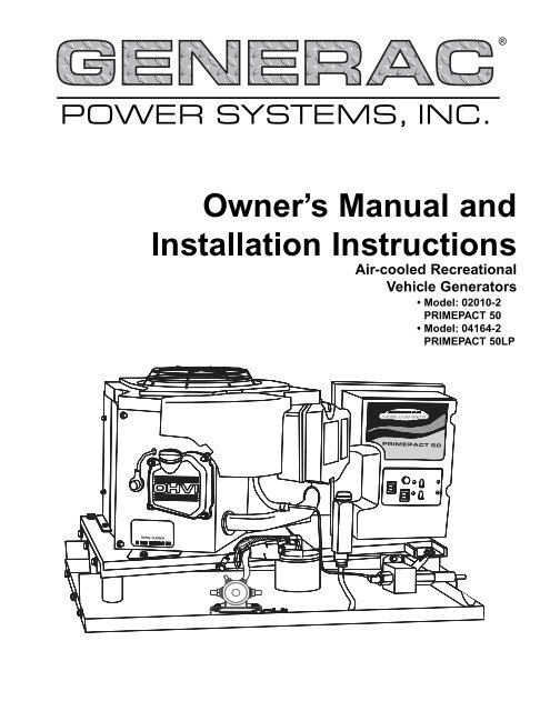
®POWER SYSTEMS, INC.Owner’s <strong>Manual</strong> andInstallation InstructionsAir-cooled RecreationalVehicle <strong>Generators</strong>• Model: 02010-2PRIMEPACT <strong>50</strong>• Model: 04164-2PRIMEPACT <strong>50</strong>LP
INTRODUCTIONThank you for purchasing this model of thePRIMEPACT product line by Generac Power SystemsInc. This model is designed and manufactured tosupply electrical power for recreational vehicles.◆ READ THIS MANUAL THOROUGHLYIf you do not understand any portion of this manual,contact Generac or your nearest Generac AuthorizedService Dealer for starting, operating and servicing procedures.Throughout this publication, and on tags anddecals affixed to the generator, DANGER, WARNING,CAUTION and NOTE blocks are used to alert you tospecial instruction about a particular operation thatmay be hazardous if performed incorrectly or carelessly.Observe them carefully. Their definitions areas follows:DANGERAfter this heading, you can read instructions that,if not strictly complied with, will result in personalinjury or property damage.After this heading, you can read instructions that,if not strictly complied with, may result in personalinjury or property damage.After this heading, you can read instructions that, ifnot strictly complied with, could result in damage toequipment and/or property.NOTE:After this heading, you can read explanatorystatements that require special emphasis.These safety warnings cannot eliminate the hazardsthat they indicate. Common sense and strict compliancewith the special instructions while performing theservice are essential to preventing accidents.Four commonly used safety symbols accompany theDANGER, WARNING and CAUTION blocks. The typeof information each indicates follows:This symbol points out important safety informationthat, if not followed, could endanger personal!safety and/or property of you and others.This symbol points out potential explosion hazard.This symbol points out potential fire hazard.This symbol points out potential electrical shockhazard.The operator (driver) is responsible for proper andsafe use of the vehicle and its equipment, and the safetyof all vehicle occupants. We strongly recommendthat the operator read this manual and thoroughlyunderstand all instructions before using this equipment.We also strongly recommend instructing otheroccupants in the vehicle to properly start and operatethe generator. This prepares them if they need to operatethe equipment in an emergency.◆ CONTENTSThis manual contains pertinent owner’s information,including warranty, electrical diagrams, explodedviews and lists of repair parts for this generatormodel. In addition, the latter portion of this manualcontains information necessary for the proper installationof these generators.◆ OPERATION AND MAINTENANCEIt is the operator's responsibility to perform all safetychecks, to make sure that all maintenance for safeoperation is performed promptly, and to have theequipment checked periodically by a GeneracAuthorized Service Dealer. Normal maintenance serviceand replacement of parts are the responsibility ofthe owner/operator and, as such, are not considereddefects in materials or workmanship within theterms of the warranty. Individual operating habitsand usage contribute to the need for maintenanceservice.Proper maintenance and care of your generatorensure a minimum number of problems and keepoperating expenses at a minimum. See your GeneracAuthorized Service Dealer for service aids and accessories.◆ HOW TO OBTAIN SE<strong>RV</strong>ICEWhen your generator requires servicing or repairs,simply contact a Generac Authorized Service Dealerfor assistance. Service technicians are factory-trainedand are capable of handling all of yourservice needs.When contacting a Generac Authorized Service Dealeror the factory about parts and service, always supplythe complete model number and serial number of yourunit as given on its data decal, which is located on yourgenerator.Model No. ____________ Serial No. ______________AUTHORIZED SE<strong>RV</strong>ICEDEALER LOCATIONTo locate the GENERAC AUTHORIZED SE<strong>RV</strong>ICEDEALER nearest you, please call this number:1-800-333-1322Generac ® Power Systems, Inc.ONLY DEALER LOCATION INFORMATIONCAN BE OBTAINED AT THIS NUMBER.
Table of ContentsPRIMEPACT <strong>50</strong> Recreational Vehicle GeneratorPart I – Owner’s <strong>Manual</strong>Introduction ........................................Inside Front CoverRead This <strong>Manual</strong> Thoroughly..................................IFCContents ..................................................................IFCOperation and Maintenance......................................IFCHow to Obtain Service ..............................................IFCAuthorized Service Dealer Locator Number..............IFCSafety Rules ........................................................................2Section 1 – General Information....................................41.1 Generator Identification ........................................41.2 Generator Applicability..........................................51.3 Safety ....................................................................51.4 Generator AC Connection System..........................51.5 Specifications ........................................................5Section 2 – Operation ......................................................72.1 Generator Control Panel ........................................72.2 Optional Remote Start/Stop Panel ........................72.3 Automatic Choke (Gasoline Only) ..........................82.4 Before Starting the Engine ....................................82.5 Starting the Generator ..........................................92.6 Stopping the Generator ........................................92.7 Applying Loads to Generator ................................92.8 Summer.Winter Heat Riser System........................92.9 Protection Systems ..............................................102.10 Additional Information ........................................11Section 3 – Maintenance ..............................................123.1 Checking the Engine Oil Level ............................123.2 Changing the Engine Oil and/or Oil Filter ............123.3 Maintaining the Engine Air Cleaner ....................133.4 Clean Air Intake ..................................................133.5 Checking the Engine Spark Plug..........................133.6 Fuel Filter (Gasoline Only) ..................................143.7 Spark Arrestor Muffler ........................................143.8 Cleaning the Generator........................................143.9 Battery Maintenance ............................................143.10 Major Service <strong>Manual</strong> ..........................................153.11 Drive Belt ............................................................153.12 Exercising the Generator ....................................153.13 Out of Service Procedure ....................................16Part II – Installation InstructionsSafety Rules ......................................................................18Section 1 – General Information ................................201.1 Purpose and Scope of the <strong>Manual</strong> ......................201.2 Safety ..................................................................201.3 Standards Booklets ............................................201.4 Equipment Description........................................201.5 Generator Engine Operating Speed ....................201.6 Generator AC Connection System........................20Section 2 – Installation ..................................................222.1 Location and Support..........................................222.2 Generator Compartments ....................................232.3 Cooling and Ventilating Air ..................................262.4 Gasoline Fuel System ..........................................272.5 LP Gas Fuel System ............................................282.6 Exhaust System ..................................................302.7 <strong>Electric</strong>al Connections ........................................312.8 Battery Installation ..............................................342.9 Optional Accessories............................................34Section 3 – Post-installation Start-upAdjustments ................................................353.1 Post Installation Tests..........................................353.2 Before Initial Start-up ..........................................353.3 Initial Start ..........................................................353.4 Testing Under Load ............................................353.5 Installation Checklist ..........................................36Section 4 – Troubleshooting ........................................37Section 5 – <strong>Electric</strong>al Data ............................................38Section 6 – Exploded Views and Parts Lists ............40Section 7 – Warranty ......................................................56Generac ® Power Systems, Inc. 1
Safety RulesPRIMEPACT <strong>50</strong> Recreational Vehicle GeneratorSAVE THESE INSTRUCTIONS – The manufacturer suggests that these rules for safeoperation be copied and posted in potential hazard areas of the recreational vehicle.Safety should be stressed to all operators and potential operators of this equipment.! !Study these SAFETY RULES carefully beforeinstalling, operating or servicing this equipment.Become familiar with this manual and with the unit.The generator can operate safely, efficiently and reliablyonly if it is properly installed, operated and maintained.Many accidents are caused by failing to followsimple and fundamental rules or precautions.Generac cannot possibly anticipate every possible circumstance that might involve a hazard. The warningsin this manual, and on tags and decalsaffixed to the unit, are, therefore, not all-inclusive. Ifyou use a procedure, work method or operating techniqueGenerac does not specifically recommend, youmust satisfy yourself that it is safe for you and others.You also must make sure the procedure, workmethod or operating technique that you choose doesnot render the generator unsafe.!!! WARNING: !The engine exhaust from this productcontains chemicals known to the stateof California to cause cancer, birthdefects or other reproductive harm.! WARNING: !This product contains or emits chemicalsknown to the state of California to causecancer, birth defects or other reproductive harm.DANGERDespite the safe design of this generator,operating this equipment imprudently, neglectingits maintenance or being careless can causepossible injury or death. Permit only responsibleand capable persons to operate or maintain thisequipment.Potentially lethal voltages are generated bythese machines. Ensure all steps are taken torender the machine safe before attempting towork on the generator.Parts of the generator are rotating and/or hotduring operation. Exercise care near runninggenerators.!GENERAL HAZARDS• For safety reasons, Generac recommendsthat the installation, initial start-up and maintenanceof this equipment is carried out by aGenerac Authorized Service Dealer.• The generator engine releases DEADLY carbonmonoxide gas through its exhaust system. Thisdangerous gas, if breathed in sufficient concentrations,can cause unconsciousness or even death.Never operate the generator set with the vehicleinside any garage or other enclosed area. DO NOTOPERATE THE GENERATOR IF THE EXHAUSTSYSTEM IS LEAKING OR HAS BEEN DAMAGED.SYMPTOMS OF CARBON MONOXIDE POISON-ING ARE (a) inability to think coherently, (b) nausea,(c) vomiting, (d) twitching muscles, (e) throbbingtemples, (f) dizziness, (g) headaches, (h)weakness, and (i) sleepiness. IF YOU EXPERI-ENCE ANY OF THESE SYMPTOMS, MOVE INTOFRESH AIR IMMEDIATELY. IF SYMPTOMS PER-SIST, GET MEDICAL HELP. Shut down the generatorand do not operate it until it has been inspectedand repaired.• Never sleep in the vehicle while the genset is runningunless the vehicle has a working carbonmonoxide detector. The exhaust system must beinstalled in accordance with the genset installationmanual. Make sure there is ample fresh air whenoperating the genset in a confined area.• The engine exhaust fumes contain carbon monoxide,which can be DEADLY. This dangerous gas, ifbreathed in sufficient concentrations, can causeunconsciousness or even death. Thus, the exhaustsystem must be installed properly, in strict compliancewith applicable codes and standards.Following installation, you must do nothing thatmight render the system unsafe or in noncompliancewith such codes and standards. The generatorcompartment must be completely vapor-sealedfrom the vehicle interior. There must be no possibilityof exhaust fumes entering the vehicle interior.Never operate this equipment with a leaking ordefective exhaust system.• Keep hands, feet, clothing, etc., away from drivebelts, fans, and other moving or hot parts. Neverremove any drive belt or fan guard while the unit isoperating.!2 Generac ® Power Systems, Inc.
Safety RulesPRIMEPACT <strong>50</strong> Recreational Vehicle Generator• Adequate, unobstructed flow of cooling and ventilatingair is critical to correct generator operationand is required to expel toxic fumes and fuelvapors from the generator compartment. Withoutsufficient cooling airflow, the engine/generatorquickly overheats, which causes serious damage tothe generator. Do not alter the installation or permiteven partial blockage of ventilation provisions,as this can seriously affect safe operation of thegenerator.• When working on this equipment, remain alert atall times. Never work on the equipment when youare physically or mentally fatigued.• Inspect the generator regularly, and contact yournearest Generac Authorized Service Dealer immediatelyfor parts needing repair or replacement.• Before performing any maintenance on the generator,disconnect its battery cables to prevent accidentalstart up. Disconnect the cable from the batterypost indicated by a NEGATIVE, NEG or (–)first. Reconnect that cable last.• Never use the generator or any of its parts as astep. Stepping on the unit can stress and breakparts, and may result in dangerous operating conditionsfrom leaking exhaust gases, fuel leakage,oil leakage, etc.ELECTRICAL HAZARDS• The generator covered by this manual producesdangerous electrical voltages and can cause fatalelectrical shock. Avoid contact with bare wires, terminals,connections, etc., while the unit is running.Ensure all appropriate covers, guards and barriersare in place before operating the generator. If youmust work around an operating unit, stand on aninsulated, dry surface to reduce shock hazard.• Do not handle any kind of electrical device whilestanding in water, while barefoot, or while handsor feet are wet. DANGEROUS ELECTRICALSHOCK MAY RESULT.• During installation onto the vehicle, have the generatorproperly grounded (bonded) either by solidmounting to the vehicle frame or chassis, or bymeans of an approved bonding conductor. DO NOTdisconnect the bonding conductor, if so equipped.DO NOT reconnect the bonding conductor to anygenerator part that might be removed or disassembledduring routine maintenance. If the groundingconductor must be replaced, use only a flexible conductorthat is of No. 8 American Wire Gauge (AWG)copper wire minimum.• In case of accident caused by electric shock, immediatelyshut down the source of electrical power. Ifthis is not possible, attempt to free the victim fromthe live conductor. AVOID DIRECT CONTACTWITH THE VICTIM. Use a nonconducting implement,such as a rope or board, to free the victimfrom the live conductor. If the victim is unconscious,apply first aid and get immediate medicalhelp.• Never wear jewelry when working on this equipment.Jewelry can conduct electricity resulting inelectric shock, or may get caught in moving componentscausing injury.FIRE HAZARDS• For fire safety, the generator must be installed andmaintained properly. Installation always mustcomply with applicable codes, standards, laws andregulations. Adhere strictly to local, state andnational electrical and building codes. Complywith regulations the Occupational Safety andHealth Administration (OSHA) has established.Also, ensure that the generator is installed inaccordance with the manufacturer’s instructionsand recommendations. Following proper installation,do nothing that might alter a safe installationand render the unit in noncompliance with theaforementioned codes, standards, laws and regulations.• Keep a fire extinguisher in the vehicle at all times.Extinguishers rated “ABC” by the National FireProtection Association are appropriate for use onthe recreational vehicle generator electrical system.Keep the extinguisher properly charged and befamiliar with its use. If you have any question pertainingto fire extinguishers, consult your local firedepartment.EXPLOSION HAZARDS• Do not smoke around the generator. Wipe up anyfuel or oil spills immediately. Ensure that no combustiblematerials are left in the generator compartment,or on or near the generator, as FIRE orEXPLOSION may result. Keep the area surroundingthe generator clean and free from debris.• Gasoline is extremely FLAMMABLE and its vaporsare EXPLOSIVE. Do not permit smoking, openflame, sparks or any source of heat in the vicinitywhile handling gasoline. Comply with all laws governingthe storage and handling of gasoline.• This generator may use liquid propane (LP) gas asa fuel. LP gas is highly EXPLOSIVE. The gas isheavier than air and tends to settle in low areaswhere even the slightest spark can ignite the gasand cause an explosion.Generac ® Power Systems, Inc. 3
Section 1 – General InformationPRIMEPACT <strong>50</strong> Recreational Vehicle Generator1.1 GENERATOR IDENTIFICATIONPlease record the following information from the generator DATA DECAL or information decal.1. Model Number ____________________ 2. Serial Number __________________3. kW Rating__________________________ 4. Rated Voltage __________________1817Model: 02010-2 — PRIMEPACT <strong>50</strong>1. Generator Air Intake2. Engine Start/Stop Switch3. Fuse4. Optional Remote PanelReceptacle (behindcontrol panel)5. Generator AC Output Leads(behind control panel)6. Fuel Primer Switch7. Circuit Breaker8. Circuit Breaker9. Starter Contactor10. Fuel Inlet11. Fuel Pump12. Fuel Filter13. Oil Filter14. Oil Drain Cap15. Oil Dipstick16. Data Decal17. Oil Fill18. Spark PlugModel: 04164-2 — PRIMEPACT <strong>50</strong>LP1. Generator Air Intake2. Engine Start/Stop Switch3. Fuse4. Optional Remote PanelReceptacle (behindcontrol panel)5. Generator AC Output Leads(behind control panel)6. Fuel Primer Switch7. Circuit Breaker8. Circuit Breaker9. Starter Contactor10. Fuel Solenoid11. Demand Regulator12. Oil Filter13. Oil Drain Cap14. Oil Dipstick15. Data Decal16. Oil Fill17. Spark Plug4 Generac ® Power Systems, Inc.
Section 1 – General InformationPRIMEPACT <strong>50</strong> Recreational Vehicle Generator1.2 GENERATOR APPLICABILITYThese generators have been designed and manufacturedfor supplying electrical power for recreationalvehicles. You should not modify the generator or useit for any application other than for what it wasdesigned. If there are any questions pertaining to itsapplication, write or call the factory. Do not use theunit until you have been advised by a competentauthority.For fire safety, the generator must have beenproperly installed in compliance with ANSI119.2-1975/NFPA <strong>50</strong>1C-1974, “Standard forRecreational Vehicles, Part III – Installation of<strong>Electric</strong>al Systems.” The generator also musthave been installed in strict compliance withthe manufacturer’s detailed installation instructions.After installation, do nothing that mightrender the unit in noncompliance with suchcodes, standards and instructions.You can use this generator to supply electrical power foroperating 120/240-volt, single-phase, 60 Hertz, AC electricalloads. These loads can require up to 4,800 watts(4.8 kW) of power, but cannot exceed 40 AC amperes ofcurrent at 120 volts, or 20 AC amperes at 240 volts forthe PRIMEPACT <strong>50</strong> (model 02010-2). For thePRIMEPACT <strong>50</strong>LP (model 04164-2), the loads canrequire up to 4,<strong>50</strong>0 watts (4.5 kW) of power, but cannotexceed 37.5 amperes of current at 120 volts, or18.8 amperes at 240 volts.!DANGERDo not overload the generator. Some installationsmay require that electrical loads be alternatedto avoid overloading. Applying excessivelyhigh electrical loads may damage the generatorand may shorten its life. Add up the ratedwatts of all electrical lighting, appliance, tooland motor loads the generator will power atone time. This total should not be greater thanthe wattage capacity of the generator. If anelectrical device nameplate gives only volts andamps, multiply volts times amps to obtain watts(volts x amps = watts). Some electric motorsrequire more watts of power (or amps of current)for starting than for continuous operation.1.3 SAFETYBefore attempting to use the generator set, carefullyread the “Safety Rules” section of this manual.Comply strictly with these rules to prevent accidentsand damage to equipment and/or property. We suggestcopying and posting the “Safety Rules” in potentialhazard areas of the vehicle. Stress safety to alloperators and potential operators of this equipment.1.4 GENERATOR ACCONNECTION SYSTEMThis generator set is equipped with dual stator ACpower windings. These two-stator windings supplyelectrical power to customer electrical loads bymeans of a dual two-wire connection system. Note,however, that the neutral is grounded.The generator may have been installed so that it powers120-volt AC loads (Figure 1.1). It can be wired toconnect both 120- and/or 240-volt AC electrical loads.This procedure should be done by a GeneracAuthorized Service Dealer or other qualified installer.Figure 1.1 – Connections for 120 Volts Only1.5 SPECIFICATIONS◆1.5.1 FUEL REQUIREMENTSThe PRIMEPACT series generator is equipped with agasoline fuel system. Depending on the installation, thegenerator may have either a separate fuel tank, or itmay “share” the vehicle engine’s fuel tank.NOTE:Some installations using a “shared” fuel tank mayhave a generator fuel pickup tube that is shorterthan the vehicle engine’s pickup tube. Such anarrangement causes the generator engine to “runout of gas” while adequate fuel for the vehicleremains in the tank.To reduce lead and carbon deposits use high qualityUNLEADED gasoline with the generator. Leaded REG-ULAR grade gasoline is an acceptable substitute.NOTE:Using unleaded gasoline contributes to longerengine valve life by reducing lead and carbondeposits.Generac ® Power Systems, Inc. 5
Section 1 – General InformationPRIMEPACT <strong>50</strong> Recreational Vehicle Generator!Generac does not recommend using anygasoline containing alcohol (such as “gasohol”).If you use any gasoline containing alcohol, itmust not contain more than 10 percent ethanol,and it must be removed from the generatorduring storage. Do NOT use any gasolinecontaining methanol. If you use gasoline withalcohol, inspect more frequently for fuel leaksand other abnormalities.◆ 1.5.2 OPTIONAL PROPANE FUEL SYSTEMThe PRIMEPACT <strong>50</strong>LP series generator is equippedwith a liquid propane (LP) gas fuel system. LP gas isusually supplied as a liquid in pressure tanks.PRIMEPACT series generators require a vapor withdrawaltype fuel system. This type of gaseous fuel systemuses the vapors forming above the liquid fuel inthe storage tank. Air temperature around the storagetank must be high enough to sustain adequate fuelvaporization. In colder climates, you may need to usean independent heat source to be sure the fuel sufficientlyvaporizes in the storage tank.LP gas may consist of propane, butane or a mixtureof the two gases. Propane vaporizes at temperaturesas low as -20° F (-29° C), but butane returns to its liquidstate when the temperature drops below about32° F (0° C). For that reason, a higher ratio ofpropane is desired in the gas mixture when temperaturesdrop below freezing.◆1.5.3 FUEL CONSUMPTIONModel No Load 1/2 Load Full LoadPRIMEPACT <strong>50</strong> 0.32 0.46 0.76(02010-2)PRIMEPACT <strong>50</strong> LP 0.47/17.05 0.72/3.06 1.25/45.35(04164-2)Gasoline is in gal/h.LP is in gal/h and cf/h.◆1.5.4 ENGINE OIL REQUIREMENTSUse only high quality detergent oil rated withAmerican Petroleum Institute (API) ServiceClassification SF, SG or SH. The recommended oilweights include the following:• During summer months: SAE 30. An acceptablesubstitute is SAE 10W-30.• During winter months: SAE 5W-30. DO NOT USESAE 10-W40.Crankcase and oil filter capacity is approximately1,400 mL or 1.5 U.S. quarts. Do NOT use specialadditives. See Sections 3.1 and 3.2 (Page 12) for oillevel check and fill procedures.6 Generac ® Power Systems, Inc.1.5.5 ENGINE◆Type of Engine ....................................GN-410, Single-cylinderCooling Method..........................................................Air-cooledRated Horsepower ..........................................15 @ 4,200 rpmDisplacement....................................................................407ccCylinder Block ..........................Aluminum w/Cast Iron SleeveType of Governor ..............................Mechanical, Fixed SpeedAir Cleaner..........................Paper Element w/Foam PrecleanerStarter..........................................................12-volt DC <strong>Electric</strong>Ignition System........................Solid-state w/Flywheel MagnetoRecommended Spark PlugChampion ..................................................................RC12YCAC....................................................................................R45SFram Autolite ......................................................................65Spark Plug Gap ........................................0.030 inch (76 mm)Recommended Minimum Battery ..............400 Cold-crankingAmperes◆ 1.5.6 GENERATORRated Maximum ContinuousAC Output (Gasoline) ............................4,800 Watts (4.8 kW)AC Output (LP Fuel) ..............................4,<strong>50</strong>0 Watts (4.5 kW)Rated Voltage ......................................................120 Volts AC*Rated Maximum ContinuousAC Current (Gasoline) ......................................40 Amperes**AC Current (LP Fuel) ....................................37.5 Amperes**Phase ................................................................................SingleRotor RPM ........................................................................3,600Number of Rotor Poles ............................................................2Engine RPM ......................................................................2,571Rated AC Frequency ........................................................60 HzBattery Charge Voltage............................................14 Volts DCBattery Charge Current..................................2 Amperes (max)WeightGasoline................................................................198 PoundsLP Fuel..................................................................200 PoundsLength ....................................................25.5 inches (648 mm)Width....................................................18.88 inches (479 mm)Height ..................................................16.75 inches (425 mm)*All units are reconnectable to 120- and/or 240-volt, dual voltageoutput. Units are no longer listed per <strong>RV</strong>IA/ANSI when reconnectedfor dual voltage output.**If reconnected for dual voltage, the ampere rating for 240 volts is20 AC amperes for model PRIMEPACT <strong>50</strong> (02010-2), and 18.8AC amperes for model PRIMEPACT <strong>50</strong> LP (04164-2).◆ 1.5.7 EMISSIONS COMPLIANCE PERIODFor non-handheld engines the Emissions CompliancePeriod referred to on the Emissions ComplianceLabel indicates the number of operating hours forwhich the engine has been shown to meet Federalemission requirements.• For engines less than 225 cc displacement,Category C=125 hours, B=2<strong>50</strong> hours, and A=<strong>50</strong>0hours.• For engines of 225 cc or more, Category C=2<strong>50</strong>hours, B=<strong>50</strong>0 hours, and A=1000 hours.
Section 2 – OperationPRIMEPACT <strong>50</strong> Recreational Vehicle Generator2.1 GENERATOR CONTROL PANELThe following features are mounted on the generatorcontrol panel (Figure 2.1):Figure 2.1 – Generator Control Panel◆ 2.1.1 FUEL PRIMERBefore starting a cold engine (if it has not been startedin more than two weeks), you must press thisswitch for approximately 10 to 15 seconds to bringfuel from the tank to the carburetor. This rocker typeswitch springs back into its original position whenyou release it. It is not necessary to press the primerswitch for LP units.NOTE:If the PRIMEPACT <strong>50</strong> has been reconnected fordual voltage AC output (120/240 volts), you caninstall line breakers having an amperage ratingthat is different than that stated in Section 1.4(Page 5). The replacement line breakers consist oftwo separate breakers (one 20 amp, and one 30amp) with a connecting piece between the breakerhandles (so that both breakers will operate at thesame time). If the unit is reconnected for dualvoltage, it is no longer <strong>RV</strong>IA listed.2.2 OPTIONAL REMOTESTART/STOP PANELA remote mounted Start/Stop Panel (Figure 2.2) isavailable that allows you to start and stop the generatorengine conveniently from inside the vehicle. Theremote panel includes a Start/Stop switch, hourmeter,generator run lamp and a wire harness.Figure 2.2 — Optional Remote Panel(Models 004057 and 004184)◆ 2.1.2 START/STOP SWITCHTo crank and start the engine, hold this switch in theSTART position. Release the switch when the enginestarts. To stop an operating engine, press and holdthe switch in the STOP position until the engine shutsoff. The switch center position is the RUN position.◆ 2.1.3 FUSEThe fuse protects the engine’s DC control circuitagainst electrical overload. If the fuse element hasmelted open due to overloading, the engine cannot becranked. If you must replace the fuse, use only anidentical replacement.◆ 2.1.4 MAIN BREAKERThe main breaker protects the generator’s AC outputcircuit against overload and provides a method ofturning OFF the generator’s 120/240-volt AC outputto the vehicle circuits. The PRIMEPACT <strong>50</strong> has one20-amp breaker and one 30-amp breaker.Generac ® Power Systems, Inc. 7
Section 2 – OperationPRIMEPACT <strong>50</strong> Recreational Vehicle Generator2.3 AUTOMATIC CHOKE (GASOLINE ONLY)The engine is equipped with an automatic choke thatconsists of two main components: a choke solenoidand prechoke.◆ 2.3.1 CHOKE SOLENOIDDuring engine cranking (Start/Stop switch atSTART), a solid-state choke module signals thechoke solenoid to activate and cycle (choke on/chokeoff) until the engine starts. The choke solenoid thusopens and closes the carburetor choke valve onlywhen the engine is cranking. When the engine starts,the choke stops cycling.◆ 2.3.2 PRECHOKEThe choke system also has a temperature-sensitivemetal strip that adjusts choke valve angle accordingto ambient temperatures (i.e., in cold ambient temperatures,choke valve closes more). Once the enginestarts, an element heats the temperature-sensitivestrip to a normal operating condition, opening thechoke valve. This may take about three minutes incooler weather.2.4 BEFORE STARTING THE ENGINENOTE:Instructions and information in this manualassume the generator has been properly installed,connected, serviced, tested and adjusted by aqualified installation technician or installationcontractor.◆ 2.4.1 INSTALLATIONGenerator installation must have been properly completedso it complies with all applicable codes, standardsand regulations and with the manufacturer'srecommendations.◆2.4.2 ENGINE LUBRICATIONHave the engine crankcase properly serviced with therecommended oil before starting. Refer to Section 1.5.4(Page 6) and Sections 3.1 and 3.2 (Page 12) for oil servicingprocedures and recommendations.◆ 2.4.3 FUEL SUPPLYThe engine must have an adequate supply of properfuel to operate. Before starting it, check that sufficientfuel is available.NOTE:Depending on the installation, the generator mayhave either a separate fuel tank, or it may “share”the vehicle engine’s fuel tank.◆ 2.4.4 COOLING AND VENTILATING AIRAir inlet and outlet openings in the generator compartmentmust be open and unobstructed for continuedproper operation. Without sufficient cooling andventilating airflow, the engine/generator quickly overheats,which causes it to shut down and may damagethe generator.◆ 2.4.5 ENGINE EXHAUST GASBefore starting the generator engine, you should besure there is no way for exhaust gases to enter thevehicle interior and endanger people or animals.Close windows, doors and other openings in the vehiclethat, if open, might permit exhaust gases to enterthe vehicle.!DANGERThe generator engine releases DEADLY carbonmonoxide gas through its exhaust system. Thisdangerous gas, if breathed in sufficient concentrations,can cause unconsciousness or evendeath. Never operate the generator set withthe vehicle inside any garage or other enclosedarea. DO NOT OPERATE THE GENERATOR IF THEEXHAUST SYSTEM IS LEAKING OR HAS BEENDAMAGED. SYMPTOMS OF CARBON MONOX-IDE POISONING ARE (a) inability to think coherently,(b) nausea, (c) vomiting, (d) twitchingmuscles, (e) throbbing temples, (f) dizziness, (g)headaches, (h) weakness, and (i) sleepiness. IFYOU EXPERIENCE ANY OF THESE SYMPTOMS,MOVE INTO FRESH AIR IMMEDIATELY. IF SYMP-TOMS PERSIST, GET MEDICAL HELP. Shut downthe generator and do not operate it until it hasbeen inspected and repaired.DANGER!Any attempt to crank or start the engine beforeyou have properly serviced it with the recommendedoil may result in an engine failure.!Never sleep in the vehicle while the genset isrunning unless the vehicle has a working carbonmonoxide detector. The exhaust system must beinstalled in accordance with the genset installationmanual. Make sure there is ample fresh airwhen operating the genset in a confined area.8 Generac ® Power Systems, Inc.
Section 2 – OperationPRIMEPACT <strong>50</strong> Recreational Vehicle Generator2.5 STARTING THE GENERATORNOTE:Read the vehicle manufacturer’s instructions. Theowner/operator should become familiar with thevehicle in which this generator is installed.Differences exist between vehicles. For example,some vehicles may use a transfer switch to isolatedockside power from the generator, while othervehicles may use an isolating receptacle. Somevehicles may be equipped with a DC converter,which allows the generator to power certain DClighting and other DC loads.To start the generator from either the generator controlpanel or from the optional remote panel, proceedas follows:1. Turn OFF electrical loads using the means providedin your vehicle (such as a main line circuitbreaker or transfer switch).NOTE:If starting from the generator control panel, turnOFF loads by setting the generator’s main circuitbreaker to the OFF (or open) position. If startingfrom a remote panel, turn OFF loads using themeans provided in the vehicle (such as a main circuitbreaker). <strong>Electric</strong>al load circuits will beturned ON after the generator has started, stabilizedand warmed up.2. If you have not started the engine in more thantwo weeks, press the Fuel Pump Primer switchand hold it for about 10 to 15 seconds to primethe fuel system. However, if the engine is warm,skip Step 2.3. Hold the engine Start/Stop switch in the STARTposition to crank the engine. Release the switchwhen the engine starts.If the engine does not start after it has been! cranking for 15 seconds, release the Start/Stopswitch and try again. Holding the switch forlonger than 15 seconds can damage thestarter motor.4. Let the engine run at no-load for a few minutes tostabilize and warm up.5. Turn ON electrical loads using the meansprovided (such as a main circuit breaker ortransfer switch).2.6 STOPPING THE GENERATOR1. Turn OFF all electrical loads using the meansprovided (such as a main circuit breaker ortransfer switch).2. Let generator run at no-load for a few minutes, tostabilize internal engine generator temperatures.3. Place the Start/Stop switch in its STOP position.2.7 APPLYING LOADS TO GENERATORWhen applying electrical loads to the generator,observe these guidelines:• Before applying electrical loads, let the generatorstabilize and warm up for a minute or two.• DO NOT overload the generator.◆ 2.7.1 LETTING THE ENGINE STABILIZEThe generator supplies correct rated voltage only atthe proper governed speed. Some electrical appliancesmay be extremely sensitive to voltage. Incorrectvoltages can damage such appliances.If electrical loads are applied at reduced operatingspeeds, such loads imposed on the engine when sufficientpower is not available may shorten engine life.Never turn ON electrical loads until after the generatorengine has started and stabilized at no-load.2.8 SUMMER/WINTER HEATRISER SYSTEMUnder certain weather conditions, it is possible forice to form in the venturi area of the carburetor. Thiscondition can be very dangerous because it can preventthe governor system from functioning properly,which results in a “runaway” engine.The most common weather conditions leading to thisproblem are temperatures in the range of 25° F to 35°F (-4° C to 1.7° C), along with high humidity. This iceformation also can be attributed to the load beingapplied during these weather conditions. <strong>Generators</strong>running with no-load or light loads applied usuallyhave the most problems.The Summer/Winter Lever (Figure 2.3) should be inthe WINTER position for ambient temperaturesbelow 40° F (4.4° C) and in the SUMMER position forambient temperatures above 40° F (4.4° C).Figure 2.3 – Heat Riser SystemWhen the heat riser is in the SUMMER (down) position(Figure 2.2), air is drawn into the air cleanerfrom the upper intake tube.Generac ® Power Systems, Inc. 9
Section 2 – OperationPRIMEPACT <strong>50</strong> Recreational Vehicle GeneratorWhen the heat riser is in the WINTER (up) position,air is drawn from the lower intake tube, which ispositioned to draw the heated air near the exhaustmanifold.To prevent carburetor icing, the owner/operatorshould physically position the heat riser to the properposition dependent on the temperature.◆ 2.8.1 DO NOT OVERLOAD THE GENERATORYou can read the rated wattage/amperage capacity ofyour generator on the generator data decal (seeSection 1.1 on Page 4).Applying electrical loads in excess of the unit’s ratedcapacity will cause the engine/generator to automaticallyshut down.To avoid overloading, add up the wattage of all connectedelectrical lighting, appliance, tool and motorloads. This total should not be greater than the generator’srated wattage capacity.• Most lighting, appliance, tool and motor loads indicatetheir required watts on their nameplate ordata plate. For light bulbs, simply note the wattagerating of the bulb.• If a load does not show its rated wattage, multiplythat load’s rated VOLTS times AMPS to obtainWATTS.• Induction type motors (such as those that run thevehicle’s furnace fan, refrigerator, air conditioner,etc.) need about 2-1/2 time more watts of power forstarting than for running (for a few seconds duringmotor starting). Be sure to allow for this when connectingelectrical loads to the generator. First, figurethe watts needed to start electric motors in thesystem. To that figure, add the running wattages ofother items that will be operated by the generator.• Do not apply heavy electrical loads for the first twoor three hours of operation.2.9 PROTECTION SYSTEMSFigure 2.4 – Low Oil Pressure andHigh Temperature Switches◆ 2.9.3 FIELD BOOSTThe Controller Circuit Board houses a field boostdiode and resistor that are not part of the automaticchoke circuit. These two components are part of a“field boost” circuit (Figure 2.5). During enginecranking only, a positive DC (battery) voltage is deliveredthrough the diode, resistor, brushes and sliprings, and the generator rotor. Application of thisvoltage to the rotor “flashes the field” whenever it isstarted. Flashing of the field each time the generatorstarts makes sure that a sufficiently strong magneticfield is available to produce “pickup” voltage in thestator windings.Figure 2.5 – Field Boost Circuit◆ 2.9. LOW OIL PRESSURE SWITCHThis switch (Figure 2.4) has normally closed (N.C.)contacts that are held open by engine oil pressure duringcranking and operating. Should oil pressure dropbelow a preset level, switch contacts close, and theengine automatically shuts down. The unit should notbe restarted until oil is added.◆ 2.9.2 HIGH TEMPERATURE SWITCHThis switch (Figure 2.4), which has normally open(N.O.) contacts, is mounted near the oil filter. Thecontacts close if the temperature should exceedapproximately 293º F (145º C), initiating an engineshutdown.10 Generac ® Power Systems, Inc.
Section 2 – OperationPRIMEPACT <strong>50</strong> Recreational Vehicle Generator◆ 2.9.4 OVE<strong>RV</strong>OLTAGE PROTECTIONA solid-state voltage regulator (Figure 2.6) controlsthe generator’s AC output voltage. This regulator suppliesan excitation current to the rotor. By regulatingthe rotor’s excitation current, the strength of its magneticfield is regulated and, in turn, the voltage deliveredto connected electrical loads is controlled. Whenthe AC frequency is 60 Hertz, voltage is regulated at120 volts (voltage-to-frequency ratio is 2-to-1).Figure 2.6 – Solid State Voltage Regulator◆ 2.10.2 25-HOUR CHECK-UPAfter the 25-hour break-in period, contact a GeneracAuthorized Service Dealer for the following maintenance.The vehicle owner is responsible for anycharges:• Change the engine crankcase oil and oil filter.• Check the oil level.• Inspect the cooling and ventilation openings.• Check the engine carburetor adjustments.• Check the engine ignition system.• Inspect the entire electrical system.• Inspect the engine exhaust system.◆2.10.3 ATTENTION REQUIREDAFTER SUBMERSIONIf the recreational vehicle generator has been submergedin water, it MUST NOT be started and operated.Following any submersion in water, have aGenerac Authorized Service Dealer thoroughly cleanand dry the generator.The voltage regulator also incorporates a “voltagesurge protection circuit.” This circuit prevents troublesomesurges in the generator AC output voltage.Voltage surge is a common cause of damage to electronicequipment.2.10 ADDITIONAL INFORMATION◆ 2.10.1 25-HOUR BREAK-IN PERIODThe first 25 hours of operation is the break-in periodfor the generator. Properly breaking in the generatoris essential to minimize fuel consumption and providemaximum engine performance. During this 25-hour break-in period, follow this procedure:• Run the unit at varying electrical loads to help seatthe engine piston rings properly.• Check the engine oil level frequently. Add oil ifneeded. It is normal for the generator engine toconsume more oil than is normal until the pistonrings have properly seated.• For the 75-hour operation following the break-inperiod, avoid light electrical loads. Load thegenerator at <strong>50</strong> percent (or more) of its ratedwattage capacity. Repeated light loads during these75 hours can cause improper seating of engine pistonrings, resulting in blowby and high oil consumption.• After operating the unit for 25 hours, complete thetasks recommended under Section 2.10.2.◆ 2.10.4 OPERATION IN HIGH GRASSOR BRUSHNever operate the generator while the vehicle isparked over high grass, weeds, brush, leaves or anyother combustible substance. Such materials canignite and burn from the heat of the exhaust system.The generator exhaust system becomes extremely hotduring operation and remains hot for a long timeafter it has shut down.◆ 2.10.5 EFFECTS OF MOISTURE AND DIRTKeep the generator set as clean and dry as possible.Protect the unit against excessive dust, dirt, corrosivevapors, road splash, etc. Permitting dirt and moistureto accumulate on generator windings will havean adverse effect on the insulation resistance of thosewindings.When moisture is allowed to remain in contact withwindings, some of the moisture will be retained invoids and cracks in the insulation. This causes areduced insulation resistance and will eventuallycause problems. Dirt will make the problem worse,since dirt tends to hold moisture in contact withwindings. Salt (as from sea air) also will worsen theproblem since it tends to absorb moisture from theair. Salt and moisture, when combined, form a goodelectrical conductor.Generac ® Power Systems, Inc. 11
Section 3 – MaintenancePRIMEPACT <strong>50</strong> Recreational Vehicle Generator3.1 CHECKING THE ENGINE OIL LEVELFor oil capacities and requirements, see “Engine OilRequirements,” Section 1.5.4 (Page 6). Check theengine crankcase oil level at least every eight hours ofoperation, or before you use it. To check the engineoil level, proceed as follows (see Figure 3.1):1. Be sure the generator is as level as possible.2. Remove the dipstick and wipe it dry with a clean,lint-free cloth.3. Install and tighten the dipstick cap; then, removeit again. The oil level should be at the dipstick“Full” mark.4. If necessary, remove the oil fill cap on the rockercover and slowly add oil until it reaches the dipstick“Full” mark. DO NOT FILL ABOVE THE“FULL” MARK.Never operate the engine with the oil level! below the “Add” mark on the dipstick. Doingthis could damage the engine.5. Install and tighten the oil fill cap and the dipstickbefore operating the engine.3.2 CHANGING THE ENGINE OILAND/OR OIL FILTER• Change the engine oil after the first 25 hours ofoperation (after the 25-hour break-in period, seeSection 2.10.1, Page 11). Thereafter, change theoil every 100 operating hours. Change the oil morefrequently if operating consistently under heavyload or at high ambient temperatures.• Change the engine oil filter after the first 25 hoursof operation, and every 100 operating hours thereafter.Figure 3.1 – Oil Maintenance FeaturesTo change the oil and/or oil filter, proceed asfollows (see Figure 3.1):1. Run the engine until it is thoroughly warmed up(at least five minutes) then shut OFFthe engine.2. Immediately after the engine shuts OFF, pull theoil drain hose free of its retaining clip. Removethe cap from the hose and drain the oil into asuitable container. Loosening the oil fill cap willallow the crankcase to drain faster.3. After the oil has drained, replace the cap onto theend of the oil drain hose. Retain the hose in the clip.4. With the oil drained, remove the old oil filter byturning it counterclockwise.5. Apply a light coating of clean engine oil to the gasketof the new filter.6. Screw the new filter on by hand until its gasketlightly contacts the oil filter adapter. Then, tightenthe filter an additional 3/4 to one turn.7. Remove the dipstick and wipe it dry with a clean,lint-free cloth. This will be used later to check theoil level.8. Remove the oil fill cap on the rocker cover andslowly add the proper type and amount of recommendedoil (see Section 1.5.4, Page 6).Periodically use the dipstick to check the oil leveland continue to fill the crankcase until the oilreaches the dipstick “Full” mark. DO NOT FILLABOVE THE “FULL” MARK.9. Install and tighten the oil fill cap and the dipstickbefore operating the engine.10. Start the engine and check for leaks.NOTE:Check the oil level and fill to the “FULL” markafter checking for leaks. The filter will retain someoil.12 Generac ® Power Systems, Inc.
Section 3 – MaintenancePRIMEPACT <strong>50</strong> Recreational Vehicle Generator3.3 MAINTAINING THE ENGINEAIR CLEANER◆ 3.3.1 CLEANING THE FOAM PRECLEANERClean and re-oil the foam precleaner every threemonths or every 25 hours of operation, whicheveroccurs first. Service the foam precleaner more frequentlyif operating the generator in extremely dustyor dirty conditions. Use the following procedure(Figure 3.2):1. Turn the two screws counterclockwise to loosen.2. Remove the cover, foam precleaner and paper filter.3. Remove the foam precleaner from the cover.4. Wash the foam precleaner in liquid detergent andwater.5. Wrap the foam precleaner in a clean cloth andgently squeeze it dry.6. Saturate the foam precleaner in clean engine oil.Gently squeeze it in a clean cloth to removeexcess oil and to distribute oil (DO NOT TWIST).7. Install the foam precleaner into the cover, followedby the paper filter.8. Install the cover, foam precleaner and paper filter.9. Tighten the two screws to retain the filter in place.Figure 3.2 – Engine Air Cleaner◆ 3.3.2 CLEANING OR REPLACINGTHE PAPER FILTEROnce each year or every 100 hours of operation(whichever comes first), clean or replace the paperfilter. The new replacement filter must be flame retardant.Service the paper filter more frequently if operatingthe generator in extremely dusty or dirty conditions.Use the following procedure (Figure 3.2):1. Follow steps 1-3 in Section 3.3.1; service thefoam precleaner if necessary.2. Remove the paper filter.3. Clean the air filter by tapping it gently on a solidsurface. If the filter is too dirty, replace it with anew one. Dispose of the old filter properly.4. Clean the air cleaner cover then reassemblefollowing steps 7-9 in Section 3.3.1.3.4 CLEAN AIR INTAKEClean all foreign material from the air intake (Figure3.3) at least once every 100 hours of operation. Cleanmore often if necessary.Inspect the area around the generator exhaust mufflerperiodically and remove all grass, leaves, dirt,etc., from this area.Figure 3.3 – Cleaning Air Intake3.5 CHECKING THE ENGINESPARK PLUGClean the spark plug and reset the spark plug gapevery 100 hours of operation.1. Clean the area around the base of the spark plugto keep dirt and debris out of the engine. Clean byscraping or washing using a wire brush and commercialsolvent. Do not blast the spark plug toclean.2. Remove the spark plug and check the condition.Replace the spark plug if worn or if reuse is questionable.3. Check the spark plug gap using a wire feelergauge. Adjust the gap to 0.030 inch (0.76 mm)by carefully bending the ground electrode(Figure 3.4).!Figure 3.4 – Setting the Spark Plug GapSparking can occur if the wire terminal doesnot fit firmly on the spark plug terminal end. Ifnecessary, re-form the wire terminal to obtain atight fit.Generac ® Power Systems, Inc. 13
Section 3 – MaintenancePRIMEPACT <strong>50</strong> Recreational Vehicle Generator3.6 FUEL FILTER (GASOLINE ONLY)Remove and replace the fuel filter (Figure 3.5)once each year or every 100 hours of operation,whichever comes first.Figure 3.5 – Fuel FilterFuel Filter3.8 CLEANING THE GENERATORKeep the generator set as clean and dry as possible.Protect the unit against excessive dust, dirt, corrosivevapors, road splash, etc. Permitting dirt and moistureto accumulate on generator windings will havean adverse effect on the insulation resistance of thosewindings.When moisture is allowed to remain in contact withwindings, some of the moisture will be retained invoids and cracks in the insulation. This causes areduced insulation resistance and will eventuallycause problems. Dirt will make the problem worse,since dirt tends to hold moisture in contact withwindings. Salt (as from sea air) also will worsen theproblem since it tends to absorb moisture from theair. Salt and moisture, when combined, form a goodelectrical conductor.3.7 SPARK ARRESTOR MUFFLERIf the generator is not equipped with a spark arrestorexhaust muffler and is to be used on any forest covered,brush covered or grass covered unimprovedland, you may have to install a spark arrestor. Thespark arrestor must be maintained in effective workingorder by the vehicle owner/operator.For assistance in ordering, installing and maintainingspark arrestor exhaust mufflers, contact your nearestGenerac Authorized Service Dealer.Exhaust mufflers supplied by Generac are sparkarrestor types. Generac exhaust mufflers for recreationalvehicle generators do not have a sparkarrestor screen, but are of the more efficient “toroid”or “swirl” type. To remove carbon and combustiondeposits from such mufflers, remove the plug fromthe muffler and run the engine for approximately 15minutes. Shut down the engine, let the muffler cooland install the plug.Be sure to reinstall the muffler plug tightly.Engine vibration could cause a loose plug tofall out. Without the plug in place, hot engineexhaust is directed out the opening. This hotexhaust, depending on the installation, couldbe directed to areas not able to withstand theextreme heat such as wooden floor boards orother flammable material. This could resultin a fire.!Do NOT use a forceful spray of water to cleanthe generator. Water will enter the generatorinterior and cause problems, and may also contaminatethe generator fuel system.3.9 BATTERY MAINTENANCEAll lead-acid batteries will discharge when not in use.The generator battery should be inspected as follows:◆ 3.9.1 WEEKLY• Inspect the battery posts and cables for tightnessand corrosion. Tighten and clean as necessary.• Check the battery fluid level of unsealed batteriesand, if necessary, fill with Distilled Water Only. Donot use tap water in batteries.◆ 3.9.2 EVERY SIX MONTHS• Have the state of charge and condition checked.This should be done with an automotive-type batteryhydrometer.NOTE:Servicing of the battery is to be performed orsupervised by personnel knowledgeable of batteriesand the required precautions. Keep unauthorizedpersonnel away from batteries.Damage will result if the battery connections aremade in reverse.14 Generac ® Power Systems, Inc.
Section 3 – MaintenancePRIMEPACT <strong>50</strong> Recreational Vehicle GeneratorDANGERDo not dispose of the battery in a fire. Thebattery is capable of exploding. Storage batteriesgive off explosive hydrogen gas. This gascan form an explosive mixture around the batteryfor several hours after charging. Theslightest spark can ignite the gas and cause anexplosion. Such an explosion can shatter thebattery and cause blindness or other injury.Any area that houses a storage battery must beproperly ventilated. Do not allow smoking,open flame, sparks, or any spark producingtools or equipment near the battery. Dischargestatic electricity from your body before touchingthe battery by first touching a groundedmetal surface.A battery presents a risk of electrical shockand high short circuit current. The followingprecautions are to be observed when workingon batteries:• Remove watches, rings or other metal objects;• Use tools with insulated handles;• Wear rubber gloves and boots;• Do not lay tools or metal parts on top of thebattery;• Disconnect any charging source prior to connectingor disconnecting battery terminals; and• Do not use any jumper cables or booster battery tocrank and start the generator engine. If any batteryhas discharged, remove it for recharging.• Where electrolyte contacts the eyes, flushthoroughly and immediately with water and seekmedical attention; and• Spilled electrolyte is to be washed down with anacid neutralizing agent. A common practice is touse a solution of 1 pound (<strong>50</strong>0 grams) bicarbonateof soda to 1 gallon (4 liters) or water. The bicarbonateof soda solution is to be added until theevidence of reaction (foaming) has ceased. Theresulting liquid is to be flushed with water and thearea dried.3.10 MAJOR SE<strong>RV</strong>ICE MANUALTo obtain a service manual for your generator, contactGenerac or your nearest Generac AuthorizedService Dealer or, go to www.generac.com. Make sureto identify your MODEL NUMBER and SERIES.3.11 DRIVE BELTThe engine drives the generator rotor by means of apulley and drive belt arrangement. The drive belt andpulleys are warranted for the life of the generator. Drivebelt tension was properly adjusted before the unit wasshipped from the factory. If you suspect that drive belttension is incorrect, contact a Generac AuthorizedService Dealer.3.12 EXERCISING THE GENERATORGenerac recommends that you start and operate thegenerator at least once every seven days. Letthe unit run for at least 30 minutes to “exercise”the engine.Do not open or mutilate the battery. Released! electrolyte has been known to be harmful tothe skin and eyes, and to be toxic.The electrolyte is a dilute sulfuric acid that is! harmful to the skin and eyes. It is electricallyconductive and corrosive. The followingprocedures are to be observed:• Wear full eye protection and protective clothing;• Where electrolyte contacts the skin, wash it offimmediately with water;Generac ® Power Systems, Inc. 15
Section 3 – MaintenancePRIMEPACT <strong>50</strong> Recreational Vehicle Generator3.13 OUT OF SE<strong>RV</strong>ICE PROCEDURE◆3.13.1 REMOVAL FROM SE<strong>RV</strong>ICEIf you cannot exercise the generator every seven days,and it is to be out of service longer than 30 days, preparethe generator for storage as follows:1. Start the engine and let it warm up.2. Close the fuel shutoff valve in the fuel supply lineand allow the unit to shut down.3. While the engine is still warm from running,drain the oil completely. Refill the crankcase withSAE 10W-30 oil having API classification “ForService SF.”4. Attach a tag to the engine indicating the viscosityand classification of the oil in the crankcase.5. Remove the spark plug and pour two or threetablespoons of clean, fresh engine oil into thespark plug threaded openings. Reinstall andtighten the spark plug.6. Remove the battery and store it in a cool, dryroom on a wooden board. Never store the batteryon any concrete or earthen floor.7. Clean and wipe the entire generator.◆ 3.13.2 RETURN TO SE<strong>RV</strong>ICETo return the unit to service after storage, proceedas follows:1. Check the tag on the engine for oil viscosity andclassification. Verify that the correct recommendedoil is used in the engine (see Section 1.5.4,Page 6). If necessary, drain and refill with theproper oil.2. Check the state of the battery. Fill all cells ofunsealed batteries to the proper level with distilledwater. DO NOT USE TAP WATER IN THE BAT-TERY. Recharge the battery to 100 percent state ofcharge, or, if defective, replace the battery.3. Clean and wipe the entire generator.4. Reconnect the battery. Observe battery polarity.Damage may occur if the battery is connectedincorrectly.5. Turn OFF all electrical loads. Add fuel if necessaryand then start the engine.6. Allow the unit to warm up thoroughly.7. Apply electrical loads to at least <strong>50</strong> percent of theunit’s rated wattage capacity.8. When the engine is thoroughly warmed up, shutit down.9. Your generator is now ready for service.16 Generac ® Power Systems, Inc.
PART II –INSTALLATIONINSTRUCTIONSDANGERONLY QUALIFIED ELECTRICIANS OR CONTRACTORSSHOULD ATTEMPT INSTALLATION!!
Safety RulesPRIMEPACT <strong>50</strong> Recreational Vehicle GeneratorNOTICE TO INSTALLERThese Installation Instructions have been publishedby Generac to aid in the installation of the productsdescribed in this manual. Generac assumes thatinstallation personnel are familiar with the proceduresfor installing such products, or similar productsthat Generac manufactures. Generac alsoassumes that personnel have been trained in the recommendedinstallation procedures for these productsand that such training includes (a) use of commonhand tools, (b) use of special Generac tools, and(c) use of any tools and/or equipment from other suppliers.Generac cannot possibly know of and advise therecreational vehicle trade of all conceivable methods,procedures or techniques by which to perform aninstallation. Nor can Generac anticipate every possiblehazard that might result from each installationmethod, procedure or technique. Generac has notundertaken any such wide evaluation. Therefore,people who use a method, procedure or techniquethat Generac does not specifically recommend mustfirst completely satisfy themselves that their safety,the safety of the vehicle's occupants and the product'ssafety is not endangered by the method, procedure ortechnique selected.Information, illustrations, specifications, etc., containedin these Installation Instructions are based onthe latest information available at the time of publication.Every effort has been expended to be sure thatsuch data is both accurate and current. However, themanufacturer reserves the right to change, alter orotherwise improve this product at any time withoutprior notice.!!DANGER: For fire safety, installation of a generator into a recreational vehicle must complystrictly with article 551, NFPA 70; ANSI C1-1975; AND, ANSI A119.2-1975/NFPA <strong>50</strong>1C “Standardfor Recreational Vehicles” (Part 3, “Installation of <strong>Electric</strong>al Systems”). In addition, installationmust comply with the manufacturer’s instructions and recommendations.! !DANGERDespite the safe design of this generator,operating this equipment imprudently, neglectingits maintenance or being careless can causepossible injury or death. Permit only responsibleand capable persons to operate or maintain thisequipment.Potentially lethal voltages are generated bythese machines. Ensure all steps are taken torender the machine safe before attempting towork on the generator.Parts of the generator are rotating and/or hotduring operation. Exercise care near runninggenerators.18 Generac ® Power Systems, Inc.!GENERAL HAZARDS• For safety reasons, Generac recommendsthat the installation, initial start-up and maintenanceof this equipment is carried out by aGenerac Authorized Service Dealer.• The engine exhaust fumes contain carbon monoxide,which can be DEADLY. This dangerous gas, ifbreathed in sufficient concentrations, can causeunconsciousness or even death. This exhaust systemmust be installed properly, in strict compliancewith applicable codes and standards.Following installation, you must do nothing thatmight render the system unsafe or in noncompliancewith such codes and standards. The generatorcompartment must be completely vapor sealedfrom the vehicle interior. There must be no possibilityof exhaust fumes entering the vehicle interior.Never operate this equipment with a leaking ordefective exhaust system.• Keep hands, feet, clothing, etc., away from drivebelts, fans, and other moving or hot parts. Neverremove any drive belt or fan guard while the unit isoperating.• Adequate, unobstructed flow of cooling and ventilatingair is critical to correct generator operationand is required to expel toxic fumes and fuelvapors from the generator compartment. Withoutsufficient cooling airflow, the engine/generatorquickly overheats, which causes serious damage tothe generator. Do not alter the installation or permiteven partial blockage of ventilation provisions,as this can seriously affect safe operation of thegenerator.• When working on this equipment, remain alert atall times. Never work on the equipment when youare physically or mentally fatigued.• Before performing any maintenance on the generator,disconnect its battery cables to prevent accidentalstart up. Disconnect the cable from the batterypost indicated by a NEGATIVE, NEG or (–)first. Reconnect that cable last.• Never use the generator or any of its parts as astep. Stepping on the unit can stress and breakparts, and may result in dangerous operating conditionsfrom leaking exhaust gases, fuel leakage,oil leakage, etc.• Never insert any tool or other object through openingsin the generator interior, even if the unit is notrunning. You might seriously injure yourself ordamage the equipment.!
Safety RulesPRIMEPACT <strong>50</strong> Recreational Vehicle GeneratorELECTRICAL HAZARDS• The generator covered by this manual producesdangerous electrical voltages and can cause fatalelectrical shock. Avoid contact with bare wires, terminals,connections, etc., while the unit is running.Ensure all appropriate covers, guards and barriersare in place before operating the generator. If youmust work around an operating unit, stand on aninsulated, dry surface to reduce shock hazard.• Do not handle any kind of electrical device whilestanding in water, while barefoot, or while handsor feet are wet. DANGEROUS ELECTRICALSHOCK MAY RESULT.• During installation onto the vehicle, properlyground (bond) the generator either by solid mountingto the vehicle frame or chassis, or by means ofan approved bonding conductor. DO NOT connectthe bonding conductor to any generator part thatmight be removed or disassembled during routinemaintenance. If the grounding conductor must bereplaced, use only a flexible conductor that is ofNo. 8 American Wire Gauge (AWG) copper wireminimum.• If the vehicle electrical circuits can be powered byany other source of electricity (such as a “dockside”power receptacle), there must be no possibilityof connecting the different power sources to thevehicle circuits at the same time. The dockside(utility) power source must be positively isolatedfrom the vehicle circuits whenever the generator isoperating. Failure to isolate the vehicle circuitsfrom the dockside power supply when the generatoris running may result in damage to the generatoror serious injury or death to dockside (utility)power workers due to backfeed of electrical energy.• In case of accident caused by electric shock, immediatelyshut down the source of electrical power. Ifthis is not possible, attempt to free the victim fromthe live conductor. AVOID DIRECT CONTACTWITH THE VICTIM. Use a nonconducting implement,such as a rope or board, to free the victimfrom the live conductor. If the victim is unconscious,apply first aid and get immediate medicalhelp.• Never wear jewelry when working on this equipment.Jewelry can conduct electricity resulting inelectric shock, or may get caught in moving componentscausing injury.FIRE HAZARDS• For fire safety, the generator must be installed andmaintained properly. Installation always mustcomply with applicable codes, standards, laws andregulations. Adhere strictly to local, state andnational electrical and building codes. Complywith regulations the Occupational Safety andHealth Administration (OSHA) has established.Also, ensure that the generator is installed inaccordance with the manufacturer’s instructionsand recommendations. Following proper installation,do nothing that might alter a safe installationand render the unit in noncompliance with theaforementioned codes, standards, laws and regulations.• Keep a fire extinguisher in the vehicle at all times.Extinguishers rated “ABC” by the National FireProtection Association are appropriate for use onthe recreational vehicle generator electrical system.Keep the extinguisher properly charged and befamiliar with its use. If you have any question pertainingto fire extinguishers, consult your local firedepartment.EXPLOSION HAZARDS• Do not smoke around the generator. Wipe up anyfuel or oil spills immediately. Ensure that no combustiblematerials are left in the generator compartment,or on or near the generator, as FIRE orEXPLOSION may result. Keep the area surroundingthe generator clean and free from debris.• Gasoline is extremely FLAMMABLE and its vaporsare EXPLOSIVE. Do not permit smoking, openflame, sparks or any source of heat in the vicinitywhile handling gasoline. Comply with all laws governingthe storage and handling of gasoline.• Fuel lines must be properly installed andfastened, and free of leaks. There must beno possibility of gasoline vapors entering the vehicleinterior.• You are required to install an approved, flexible,nonconductive fuel line between the generator fuelconnection point and rigid fuel lines.• If the generator is equipped with a liquid propane(LP) gas fuel system, install the unit so it complieswith all codes, standards and regulations pertainingto such systems. LP gas is highly explosive. Thegas tends to settle in low areas where even theslightest spark can ignite it and cause an explosion.Do not allow gas vapors to enter the vehicle.Generac ® Power Systems, Inc. 19
Section 1 – General InformationPRIMEPACT <strong>50</strong> Recreational Vehicle Generator1.1 PURPOSE AND SCOPEOF THE MANUALThese Installation Instructions have been preparedespecially for the purpose of familiarizing installersand owners of the applicable equipment with theproduct's installation requirements. Give seriousconsideration to all information and instructions inthe manual, both for safety and for continued reliableoperation of the equipment.Because of the different recreational vehicle modelsand the variations between the models, it would beextremely difficult, if not impractical, to providedetailed instructions for every possible installation.For that reason, instructions and illustrations in thismanual are general in nature. Illustrations are notintended to serve as detailed installation blueprints.The installation should comply strictly with allapplicable codes, standards and regulations pertainingto the installation and use of this product. If anyportion of this manual appears to be in conflict withsuch codes, standards or regulations, the applicablecodes, standards or regulations must take precedenceover the manual.1.2 SAFETYBefore handling, installing, operating or servicing thisequipment, carefully read the “Notice to Installer”and “Safety Rules” on Pages 18 and 19. Comply withall safety rules to prevent death, personal injury ordamage to equipment and/or property. Stress safetyto all installers, operators and service technicianswho work on this equipment.1.3 STANDARDS BOOKLETSInstallation, use and servicing of this equipmentshould comply strictly with published standards, aswell as the manufacturer's recommendations. Thefollowing standards booklets (latest revision) areavailable from the sources indicated:1. NFPA Standard <strong>50</strong>1C, “Standard for RecreationalVehicles,” available from the National FireProtection Association, Batterymarch Park,Quincy, MA 02269.2. NFPA 70, “NFPA Handbook of the National<strong>Electric</strong> Code,” available same as Item 1.3. ANSI C1-1975 and ANSI 119.2-1975, availablefrom the American National Standards Institute,1430 Broadway, New York, NY 10018.4. ANSI A119.2/NFPA <strong>50</strong>1C, available from theRecreational Vehicle Association, 1896 PrestonWhite Drive, Reston, VA 22090.5. California Administrative Code, Title 25, availablefrom the State of California, DocumentsSection, P.O. Box 1015, North Highlands,CA 95660.20 Generac ® Power Systems, Inc.6. CSA <strong>Electric</strong>al Bulletin 946, available from theCanadian Standards Association, Housing andConstructions Materials Section, 178 RexdaleBoulevard, Rexdale, Ontario, Canada, M9W 1R3.1.4 EQUIPMENT DESCRIPTIONInstructions and information in this section pertainto Generac air-cooled generators. These generatorsare designed specifically for installing in recreationalvehicles. They operate 120-volt, single-phase, 60-Hertz, AC electrical loads that require 40.0 amps(gasoline) or 37.5 amps (LP fuel) at 120 volts.1.5 GENERATOR ENGINEOPERATING SPEEDThe generator’s revolving field (rotor) is driven by asingle-cylinder, four-cycle engine through a pulley anddrive belt arrangement. The generator supplies 120volts AC at 60 Hertz when the rotor is operating at3,600 rpm.The drive belt arrangement allows theengine to operate at a lower speed than the rotor.1.6 GENERATOR ACCONNECTION SYSTEMThe generator is equipped with dual stator powerwindings as shown in Figure 1.1.Figure 1.1 – 120-volt Single Voltage Connection• The AC connection system on all air-cooledPRIMEPACT series generators uses a GROUNDEDneutral.• A separate green ground wire is connected to therecreational vehicle’s junction box.• For these PRIMEPACT units, loads connectedacross T1 (red) to T2 (white), MUST NOT exceed30 amperes or 3,600 watts, and loads connectedacross T3 (black) and T2 (white) MUST NOTexceed 20 amperes or 2,400 watts each at 120volts. The combined loading of the two breakersshould not exceed 5,<strong>50</strong>0 watts.NOTE:Do NOT connect loads in excess of circuitbreaker ratings.
Section 1 – General InformationPRIMEPACT <strong>50</strong> Recreational Vehicle GeneratorFigure 1.2 – Major Features and DimensionsGenerac ® Power Systems, Inc. 21
Section 2 – InstallationPRIMEPACT <strong>50</strong> Recreational Vehicle Generator2.1 LOCATION AND SUPPORT◆2.1.1 GENERATOR LOCATIONThe most desirable location for the generator set isbetween the vehicle's main frame members. However,this is seldom possible. Most units must be installedon the side of the vehicle and are difficult to reinforce.Many recreational vehicles have been factoryequipped with an area for the generator set. Somevehicles may even have a generator compartmentprovided by the vehicle manufacturer.Plan the generator location based on the following:• The generator set must be installed on a frameworkthat is part of the recreational vehicle, as outlinedin Section 2.1.2.• The location must provide an access opening thatis large enough to permit generator removal(unless the generator is to be removed from underneaththe supporting framework).• The location must provide easy access to frequentlyserviced components, such as filters, oil drains,spark plugs and other common maintenanceparts.• The location must provide sufficient room to allowminimum clearances as outlined in Section 2.2. Ifsound insulation is to be used on the compartmentwalls and ceiling, the minimum recommendedapplies to the space between the generator andsuch insulation.• The location must provide adequate cooling andventilating airflow for the generator without a greatdeal of work and expense.◆ 2.1.2 GENERATOR SUPPORTThe generator must be securely attached to a metalframework that has been made part of the vehicleframe structure by bolting or welding. The metalframework on which the generator will rest andwhich will restrain the generator set should consist ofat least two horizontal beams. These beams shouldconsist of (a) 1-1/2-inch square, 11-gauge steel tubingOR (b) 1-1/2-inch, 11-gauge angle iron. A typical supportingframe with horizontal support tubing, isshown in Figure 2.1.The generator can be installed so that it sits on top ofthe horizontal support tubing if the vehicle designpermits. Another method is to suspend the generatorbelow the horizontal support tubing by means of suitable,structurally sound metal framework. The followinggeneral rules apply:• Vehicle construction MUST be capable of supportingthe weight of the generator.• Whether the generator is mounted above the horizontalsupport tubing or suspended below the tubing,the supporting frame used must be structurallysound.• If the generator cannot be bolted directly tothe supporting frame or support tubing, considerusing additional tubing, angle bracketsor other supports to give the supporting frame sufficientstrength.Figure 2.1 – Typical Horizontal Support Frame◆ 2.1.3 SUSPENDED MOUNTINGIf you are going to suspend the generator below thehorizontal support tubing, the suspension methodyou use with the vehicle frame members must (a) beable to support the weight of the generator AND (b)provide sufficient restraint for the generator. One typicalsuspended mounting system is shown in Figure2.2. The location of a suspended mounting systemmust be carefully planned, keeping the following generalrules in mind:• Protect the generator against road splash and debris.Baffles or splash guards may be required to protectcertain areas of the generator. To make sure the generatoris adequately protected, road test the installationthrough mud, water and slush.Figure 2.2 – Typical Suspended Mounting System• The installer must make certain that the selectedlocation will permit adequate cooling and ventilatingairflow to be supplied.22 Generac ® Power Systems, Inc.
Section 2 – InstallationPRIMEPACT <strong>50</strong> Recreational Vehicle Generator◆2.1.4 GENERATOR RESTRAINTUse four 3/8"-16 hardened steel bolts (Grade 5) to fastenthe generator to the supporting frame or the supporttubing. These bolts must pass through (a) the generatormounting base, (b) the compartment floor (if acompartment is used) and (c) the supporting framework(Figure 2.3). All bolts must be long enough so thatwhen tight, at least three threads are visible past theretaining lock nuts. Refer to Section 2.2 for the locationof the generator mounting holes.Figure 2.3 – Typical Generator Restraint◆ 2.2.2 COMPARTMENT CONSTRUCTION• The generator compartment should be either constructedof, or lined with, 26-gauge galvanizedsteel.NOTE:Aluminum is NOT an acceptable alternativeto galvanized steel due to aluminum’s lowmelting point.• If the compartment is lined with galvanized steel, itmay be constructed of any material. Generac recommendsthat the compartment be constructed of1/2-inch thick plywood (not strandboard), with thefloor made of a double thickness of 1/2-inch plywoodwith the grain of the wood at cross sectionfor added strength (Figure 2.5).Figure 2.5 – Typical Compartment Construction2.2 GENERATOR COMPARTMENTSWhether the generator set is being installed inside acompartment specifically manufactured to house a generatoror inside a compartment that the installer constructs,the compartment MUST meet certain specificationsas outlined in the following sections:◆ 2.2.1 COMPARTMENT SIZEPlan the compartment size carefully. Provide a minimumclearance of 1/2 inch (13 mm) on the front andtop, 1 inch (25 mm) on the sides, and 1/2 inch (13mm) from the back for air circulation AFTER thecompartment has been lined with metal and soundinsulation (Figure 2.4).NOTE:Refer to “Figure 1.2 – Major Features andDimensions” on Page 21.PlywoodCompartmentInsulationFigure 2.4 – Clearances1 1/2" Clearance on Top1/2"in Front1" Each Side1" Clearancein Back• If constructing a compartment, line the exterior(underside) of the compartment floor with 26-gauge galvanized steel.• All seams, splices and joints of the compartmentwalls (unless vapor tight by design) shouldbe caulked to prevent poisonous, flammable orexplosive vapors from entering the vehicle interior.NOTE:Caulking must be done so that the caulking materialwill stay in place permanently. Pressing suchmaterials as putty tape onto joints and seams is NOTacceptable. A high quality silicone rubber basesealant is recommended.• Holes and openings made in the compartmentwalls to allow for the passage of electrical conduit,conductors, hoses, cables, etc., into the vehicle livingarea must be sealed vapor tight with siliconerubber base sealant.Generac ® Power Systems, Inc. 23
Section 2 – InstallationPRIMEPACT <strong>50</strong> Recreational Vehicle Generator• If flexible metal conduit is used, it must be sealedinternally at the end where it terminates inside thecompartment’s electrical junction box.NOTE:Flexible metal conduit, due to its unique construction,is NOT vapor tight along its entirelength.• Seams and joints of the galvanized steel (whetherused as a liner or for the compartment itself) mustbe lapped and mechanically secured. Such seamsmay be manufactured, welded, bolted, riveted orscrewed. Manufactured lock seams are shown inFigure 2.6. Installer constructed compartmentstypically utilize a standard lap joint.Figure 2.6 – Types of Lock Seams• After the compartment has been metal lined andvapor sealed, line the compartment interior wallsand ceiling with an approved, nonflammablesound insulating material. See Section 2.2.3.DANGERDo not install any flammable material directlyabove or around the compartment. Heat,transferred through the compartment structure,may be sufficient to ignite, char or discolorseat cushions, fiberboard and other flammablematerials. You may need to use approvednonflammable insulating materials in hightemperature areas.◆ 2.2.3 SOUND INSULATING MATERIALSOnce installers have determined that a compartmentis properly constructed and metal lined, they can addacoustical material. This may include additionalsealant or insulating material, to reflect noise awayfrom the vehicle interior.Sound insulating materials should be of a nonflammabletype. One excellent insulating material is a 1-inch (25 mm) thick fiberglass having a 2-pound density.When fiberglass is used, its coated side shouldface toward the compartment interior.24 Generac ® Power Systems, Inc.DANGERDo not install sound insulation or anyabsorbent material on the compartment floorinterior. Such materials will become soakedwith combustible or explosive vapors andliquids and will become a fire hazard.Using a combination of sound insulating materialscan often reduce noise more effectively than a singlematerial. For example, a sheet of lead or visco-elasticmaterial, along with a layer of other acoustical material,is more effective than when a single material isused.◆ 2.2.4 ACOUSTICSFor additional noise abatement, the installer maywish to consider the following:• Using special sound insulating materials.• Construction of a special noise abatementcompartment.NOTE:Any method used to reduce noise must notadversely affect the flow of cooling and ventilatingair into or out of the compartment.In addition to the effective use of sound insulatingmaterials, construction of a special noise abatementcompartment might be considered to reduce noiselevels. Such a compartment might be constructed asfollows (Figure 2.7):• Use 5/8-inch thick or 3/4-inch thick plywood in thecompartment.• Construct the compartment floor of a double thicknessof 5/8-inch or 3/4-inch plywood.• Line the compartment interior walls and floor, aswell as the underside of the floor, with 26-gaugegalvanized steel.• Vapor seal all compartment seams and joints.• Over the galvanized steel lining, install a combinationof acoustical materials as mentioned inSection 2.2.3.DANGERTo prevent fire or explosion, do not install anyinsulation or other absorbent materials on theinterior or underside of the compartment floor.• Seal all compartment door edges to prevent noiseleakage around the door perimeter.• Line the compartment door interior (except for airopenings) with suitable, fireproof sound insulation(such as 1-inch (25 mm) thick fiberglass with a 2-pound density).
Section 2 – InstallationPRIMEPACT <strong>50</strong> Recreational Vehicle GeneratorFigure 2.7 – Typical Noise Abatement ◆ 2.2.5 COMPARTMENT FLOOR CUTOUTSYou must provide openings in the generator compartmentfor the following items (Figure 2.8):• Engine exhaust and cooling air outlets• Generator cooling air inlet• Four holes for passage of generator mountingbolts. See Section 2.1.4 (Page 23).DANGER!Fuel lines and exhaust piping must not penetrateinto the vehicle living area.Figure 2.8 – Compartment Floor CutoutGenerac ® Power Systems, Inc. 25
Section 2 – InstallationPRIMEPACT <strong>50</strong> Recreational Vehicle Generator2.3 COOLING AND VENTILATING AIRIt is absolutely essential that an adequate flow of airfor cooling, ventilating and engine combustion besupplied to the generator set. Without sufficient airflow,the engine/generator quickly overheats. Suchoverheating can cause serious operating difficultiesand also may cause fire and personal injury. Theinstaller must make sure that sufficient air is availableto the generator for cooling, ventilating and combustion.The installer also must provide for a pathfor exhausting the cooling air to the exterior of a compartment,if so equipped.NOTE:Screening, louvers or expanded metal that cover airopenings restrict airflow. You must compensate forthis by making the actual air opening proportionatelylarger. See Section 2.3.3 (Page 27).Figure 2.10 – Air Inlet in Compartment DoorDANGERNever use discharged cooling air for heating or permitsuch air to enter the vehicle interior. This air containsdeadly carbon monoxide gas and other poisonous, flammableor explosive gases.◆2.3.1 GENERATOR AIRFLOWEngine operation drives cooling fans for the two-stagecooling air system. A pressure fan draws cooling airinto the top of the generator (Figure 2.9). This airflowcools the engine/generator and electronic components.The second part of the cooling system, a suction fan,draws air that is heated from a hot engine into a collectorpan at the base of the unit. This heated air (althoughcooler than exhaust muffler) is then deflected out thebottom toward the ground.Figure 2.9 – Airflow Through Engine/GeneratorNOTE:Be sure to meet the minimum clearances illustratedin Figure 2.4 (Page 23).When the unit is installed on a suspended mountingsystem, one of several different methods of supplyingairflow may be used as follows:• Provide a door in the vehicle skirt having an airinlet opening (Figure 2.11).Figure 2.11 – Suspended Mount: Inlet Door◆ 2.3.2 COOLING AIR INLET OPENINGSThe minimum size of the air inlet opening, whetherthe generator is housed in a conventional compartmentor not, is at least 100 square inches (seeFigure 2.10). This rule applies whether inlet air isbrought in through an opening in the compartmentdoor, an opening in the vehicle skirt, through ductwork,or by any other means.• Using ductwork (Figure 2.12, Page 27). Theinstaller must be sure air is available to thetop of the generator since air inlets are located atthe top.• By providing an opening in the vehicle skirt andspace behind the generator for cooling airflow(Figure 2.13 Page 27). Recommended clearancebehind the back of the generator is at least1/2 inch (13 mm).26 Generac ® Power Systems, Inc.
Section 2 – InstallationPRIMEPACT <strong>50</strong> Recreational Vehicle GeneratorFigure 2.12 – Air Inlet Using DuctworkFigure 2.13 – Air Inlet in Vehicle SkirtVEHICLE FLOO<strong>RV</strong>EHICLESKIRTAIRINLET◆ 2.3.4 TESTING THE INSTALLATIONGenerac recommends testing the installation to besure adequate cooling airflow is available to the unitbefore placing the unit into service. If the unit showssigns of overheating, you will need to enlarge the airopenings. Never place a unit into service untilabsolutely certain that cooling and ventilation is adequate.NOTE:You must test the installation, especially if youbring in air from below the generator set.2.4 GASOLINE FUEL SYSTEMThe installation of a gasoline fuel system (Figure2.14) for a recreational vehicle generator set mustcomply with applicable codes, standards and regulations.The entire fuel system must be completely freeof leaks. There must be no possibility of gasolinevapors entering the vehicle interior.Figure 2.14 – Generator Fuel SystemMINIMUMCLEARANCE1-1/2"◆2.3.3 COMPENSATING FOR RESTRICTIONSSuch materials as screening, louvers or expandedmetal can restrict the free flow of air. Compensate forthis restriction by making the actual air opening proportionatelylarger.Some materials may offer only a 60 percent “free airinlet area.” Other more efficient materials may provideup to a 90 percent free air inlet area. The percentageof free air inlet opening is usually availablefrom the material supplier or manufacturer.To determine the actual air inlet opening sizerequired, divide 100 square inches by the percentageof free air inlet area for the material youwill use.For example: If you plan to use screening with an 80percent free air inlet area, divide 100 by 0.8, whichresults in 125 square inches. Minimum actual size ofair inlet opening in this case is 125 square inches.DANGERGasoline is highly flammable, and its vapors areexplosive. Comply with all codes, standards andregulations pertaining to gasoline fuel systemsused in recreational vehicle generators.Properly install and maintain the fuel systemand keep it entirely free of leaks. Gasolinevapors must not enter the vehicle interior.Factory installed generator fuel system componentsinclude (a) fuel filter, (b) 12-volt DC electric pump, (c)engine carburetor, and (d) interconnecting lines andfittings. Connect a fuel supply line to the fuel filterinlet. Use a flexible length of approved fuel hosebetween the fuel filter inlet connection and rigid fuellines.Generac ® Power Systems, Inc. 27
Section 2 – InstallationPRIMEPACT <strong>50</strong> Recreational Vehicle Generator◆2.4.1 FUEL TANKEither the generator must share the vehicle engine'sfuel tank, or you must install a separate fuel tank forthe generator set. All fuel tanks installed on the vehiclemust be constructed, installed and restrained sothey comply with applicable codes, standards andregulations.If the generator is to share the vehicle engine's tank,separate fuel pickup tubes are required for the engineand the generator. Generac recommends that youmake the fuel pickup tube 2 to 3 inches (51 to 76mm) shorter than the vehicle engine's pickup tube.This prevents the generator from depleting the entirefuel supply during prolonged generator operatingperiods.!◆Do NOT tee the generator fuel supply line intothe vehicle engine fuel supply line. If this isdone, the generator will be starved of fuelwhen both engines are operating at the sametime. Also, while the vehicle engine is not running,generator operation may drain the vehicleengine supply line, making it difficult tostart the vehicle engine.2.4.2 GENERATOR FUEL SUPPLY LINE2.4.2.1 Rigid Fuel LinesThose lines used to supply fuel from a tank to thegenerator must comply with applicable codes, standardsand regulations. The following general rulesapply to rigid fuel lines:• Rigid lines should be of annealed, seamless, drawnaluminum or steel.• Lines and fittings must comply with SAE J512F,“Standard Automotive Fittings,” or with ANSIB126.26 (latest edition).• Route the fuel line so that at least 2 inches (51 mm)of clearance is maintained between the line andany exhaust system parts.• Do not attach electrical wiring to fuel lines. Routethe wiring so it cannot come into contact with anyfuel line.• Route fuel lines so if they leak, fuel does not driponto any electrical or exhaust system parts.• Use nonferrous metal straps without sharp edgesto secure fuel lines.2.4.2.2 Flexible Fuel LineUse an approved flexible length of fuel hose betweenthe generator fuel inlet connection and rigid fuellines. This prevents breaking of the line caused byvibration, shifting, settling or movement. The followingrules apply:• The flexible hose must comply with SAE J30B,“Standard for Fuel and Oil Hose.” It must beapproved for use with gasoline.• The hose should be at least 6 inches (152 mm)longer than is needed to prevent the hose fromrupturing if the generator shifts or settles.2.5 LP GAS FUEL SYSTEMDANGERLP gas is highly EXPLOSIVE. The gas is heavierthan air and tends to settle in low areas. Eventhe slightest spark can ignite it and cause andexplosion. Only competent, qualified peopleshould be allowed to install, test, adjust or servicean LP gas fuel system. Install the optionalfuel system in compliance with applicablecodes, standards and regulations. After theinstallation, do not do anything that might renderthe system in noncompliance with applicablecodes and standards.The LP powered range of generators are fitted with anonadjustable, factory set system. These systems aretamper-proof to meet 1997 California Air ResourcesBoard requirements for engine emission.◆ 2.5.1 PARTS NOT INCLUDED IN FUELSYSTEMThe propane fuel system does NOT include suchitems as (a) gas tank, (b) gas piping, (c) fittings, (d)valves, and (e) primary regulator, used to store thegaseous fuel and deliver it to the gaseous fuel solenoid(Figure 2.15, Page 29).DANGERUse only approved components in the fuel supplysystem. All components must be properlyinstalled in accordance with applicable codes.Improper installation or use of unauthorizedcomponents may result in fire or an explosion.Follow approved methods to test the systemfor leaks. No leakage is permitted. Do not allowfuel vapors to enter the vehicle interior.28 Generac ® Power Systems, Inc.
Section 2 – InstallationPRIMEPACT <strong>50</strong> Recreational Vehicle GeneratorFigure 2.15 – Typical Propane Gas Fuel System◆2.5.2 SOME IMPORTANT CONSIDERATIONSWhen installing an LP gas system, consider seriouslythe following items:• All fittings, lines, hoses and clamps must be tightand free of leaks. Apply a pipe sealant to threadswhen assembling threaded connections. Thisreduces the possibility of leakage.• Test the entire fuel system for leaks using approvedtest methods.• Optimum gas pressure at the inlet to the gaseousfuel solenoid valve and secondary regulator is 11inches water column.• The installer’s fuel supply connection point is atthe gaseous fuel solenoid valve. This is a 3/4-inch(female) connection. Provide a suitable 3/4-inchNPT (male) connector to attach to the fuel supplyline.• Use a length of approved flexible fuel hose betweenthe gaseous fuel solenoid valve and rigid gas piping.The flexible line should be at least 6 incheslonger than necessary.◆ 2.5.4 PRIMARY REGULATORGas pressure delivered to the solenoid valve must beproperly regulated by means of a primary gas regulator.Mount the primary regulator at the gas tank outletor in the supply line from the gas tank. The followingrules apply:• For best results, the primary regulator suppliesgaseous fuel to the secondary regulator at 11 incheswater column. Do NOT exceed 14 inches watercolumn.• The installer must be sure the primary regulator israted at sufficient gas flow to operate the generatorplus all other gas appliances in the circuit.NOTE:Recommended MINIMUM gas flow rate for all aircooledPRIMEPACT series generators is 67 cubicfeet per hour.If an existing primary gas regulator does not havea sufficient flow capacity for the generator andother gas appliances in the circuit, (a) install a primaryregulator with adequate flow rate, or (b)install a separate regulator only and rated at least67 cubic feet per hour. The inlet side of any primaryregulator that supplies the generator mustconnect directly to a gas pressure tank. Do NOTtee the generator line into a gas circuit feedingother areas.◆2.5.5 GASEOUS CARBURETIONLP gas vapors should be supplied to the secondaryregulator inlet at about 11 inches water column (positivepressure). The engine pistons draw air in duringthe intake stroke (Figure 2.16). This air passesthrough a carburetor venturi, which creates a lowpressure that is proportional to the quantity of airbeing pumped. The low pressure from the carburetorventuri acts on the regulator diaphragm to pull thediaphragm toward the source of low pressure. A leverattached to the diaphragm opens a valve to permitgas glow through the carburetor.Figure 2.16 – LP Gas Carburetion Diagram◆ 2.5.3 VAPOR WITHDRAWALLP gas is stored in pressure tanks as a liquid. Thegas systems used with these generators weredesigned only for vapor withdrawal type systems.Vapor withdrawal systems use the gas vapors thatform above the liquid fuel in the tank. Do NOTattempt to use the generator with any liquid withdrawaltype system.Generac ® Power Systems, Inc. 29
Section 2 – InstallationPRIMEPACT <strong>50</strong> Recreational Vehicle GeneratorThe greater the airflow through the carburetor venturi,the lower the pressure at the venturi throat. Thelower the pressure at the venturi throat, the greaterthe diaphragm movement, and the greater the movementof the regulator valve. The more the regulatorvalve opens, the greater the gas flow that is proportionalto airflow through the generator.The following facts about the secondary regulatormust be emphasized:• The regulator must be sensitive to venturi throatpressure changes throughout the operating range.• The regulator must be properly adjusted so it willstop the flow of gas when the engine is not running(no air flow through the carburetor).• The slightest airflow (and vacuum in the venturithroat) should move the regulator valve off its seatand permit gas to flow.◆ 2.5.6 FUEL SUPPLY LINES• LP gas lines must be accessible, but protectedagainst possible damage.• Do NOT connect electrical wiring to any LP gas fuelline or run wiring alongside the lines.• Route gas lines away from hot engine exhausts.• Retain gas lines with metal clamps that do not havesharp edges.• Install an approved length of flexible hose betweenthe gaseous fuel solenoid valve and rigid fuel supplylines. The flexible line must be nonmetallic,nonorganic and nonconductive. It must beapproved for use with LP gas.◆ 2.5.7 EXCESS FLOW VALVELP gas tanks should have an excess flow valve,according to NFPA <strong>50</strong>1C, Paragraph 3-4.4. This valveand the gas lines must be carefully sized so the valvewill close when a fuel line is severed or broken.Consult the Natural-LP Gas Association for informationand limitations of excess flow valves.<strong>Manual</strong> shutoff valves on the supply tank and elsewherein the system must be fully open when operatingthe generator. The excess flow valve functionsproperly only if all valves are fully open.◆ 2.5.8 LEAKAGE TESTSDo not place the generator into service until you haveproperly tested the gas system for leaks. To test thesystem, you need a separate source of 12 volts DC toopen the gaseous fuel solenoid valve.The leak test must comply fully with NFPA,Paragraph 318. All connections, hoses, valve regulators,fittings, and other fuel system parts must betested under gas or air pressure of not less than 90psi (620 kPa), while using soap and water or anequivalent solution to check for leaks. Otherapproved methods of testing for leaks may be used, ifappropriate. DO NOT USE ANY FLAME TO TESTFOR LEAKS.Gaseous fuel lines between the tank and thesecondary regulator are under a positive pressure(about 11 inches water column). Gas pressureat the outlet side of the secondary regulator,however, is a negative pressure and candraw flame inside a line or fitting and cause anexplosion.2.6 EXHAUST SYSTEMThe generator exhaust system must be safely andproperly installed. Only approved mufflers and otherexhaust system parts must be used. A properlyinstalled exhaust system must be vapor tight, quietand completely safe.!!DANGERDANGERThe generator engine gives off DEADLY carbonmonoxide gas through its exhaust system. Thisdangerous gas, if breathed in sufficient concentrations,can cause unconsciousness or evendeath. Never operate the generator set withthe vehicle inside any garage or other enclosedarea. DO NOT OPERATE THE GENERATOR IF THEEXHAUST SYSTEM IS LEAKING OR HAS BEENDAMAGED. SYMPTOMS OF CARBON MONOX-IDE POISONING ARE (a) inability to think coherently;(b) vomiting; (c) twitching muscles; (d)throbbing temples; (e) dizziness; (f) headaches;(g) weakness; and (h) sleepiness. IF YOU FEELANY OF THESE SYMPTOMS, MOVE INTO FRESHAIR IMMEDIATELY. IF SYMPTOMS PERSIST, GETMEDICAL HELP. Do not operate the generatoruntil its exhaust system has been inspected andproperly repaired.Never tee the generator engine exhaust pipeinto the vehicle engine exhaust piping. Thiscauses excessive back pressure on the generatorengine. Also, water from one engine candamage the other engine.30 Generac ® Power Systems, Inc.
Section 2 – InstallationPRIMEPACT <strong>50</strong> Recreational Vehicle Generator◆2.6.1 MUFFLERS AND SPARK ARRESTORSThis muffler meets code and standard requirementsof the U.S. Forest Service. Use only mufflers andparts approved by Generac. Any person(s) installingan unapproved muffler, or an unapproved exhaustsystem part, or modifying an exhaust system in anyway that might cause a hazard, is liable for any damage,injury or warranty expense that might be causedby such unapproved installation or modification.Failure to provide and maintain a spark arrestor maybe in violation of the law. If this generator is used onany forest covered, brush covered or grass coveredunimproved land, you must provide a spark arrestor.The vehicle owner or operator must maintain thisdevice in good condition. In the state of California,the preceding is required by law (Section 4442 of theCalifornia Public Resources Code). Other states mayhave similar laws. Federal laws apply on federallands.◆ 2.6.2 TYPE OF EXHAUST SYSTEMTwo types of exhaust systems for PRIMEPACT seriesgenerators are available from Generac. They includethe following:• “Out-the-bottom” exhaust system dimensions are15/16” O.D., model 9742.• “Out-the-side” exhaust system dimensions are 1-1/4” O.D., 18 gauge, model 4172.NOTE:No matter what type of exhaust kit best fits yourrecreational vehicle, the mounting base has openingsfor either “bottom-out” or “side-out” exhaustsystems. Use the cover plate provided with thegenerator to cover the opening you do NOT use.◆ 2.6.3 EXHAUST SYSTEM SAFETY• Maintain a clearance of at least 3 inches (76 mm)between exhaust system parts and any combustiblematerial (such as wood, felt, cotton,organic fibers or other like material). If you cannotmaintain the 3-inch (76 mm) clearance, locate,insulate or shield the exhaust part(s) so that thetemperature of any combustible material is notraised more than 117° F (65° C) above the ambientair temperature.• Extend the exhaust system at least 1 inch (25 mm)past the outer edge of the vehicle. Do not terminatethe exhaust system under the vehicle.• Terminate the exhaust tailpipe such that exhaustgases will not be drawn back into the generatorcompartment and recirculated.• If there is any possibility of the tailpipe or mufflerbeing damaged, protect these damage-prone areasby means of a protective device (such as a skidbar).• Install the generator exhaust system according tosafe automotive practices.• Use enough exhaust system hangers to prevent anypart of the system from being dislocated.• Use exhaust system parts recommended byGenerac. Using unapproved exhaust mufflers andexhaust system parts is the responsibility of theperson(s) installing such unauthorized parts.• Do not terminate the exhaust system under anyopening, window or vent that can be opened or isnot permanently sealed from the vehicle interior.• Exhaust piping must be large enough to preventexcessive back pressure on the generator engine.• Never tee the generator engine exhaust pipe intothe vehicle engine exhaust piping. This causesexcessive back pressure on the generator engine.Also, water from one engine can damage the otherengine.• Plan exhaust system installation carefully. Complywith all applicable codes, standards and regulations.2.7 ELECTRICAL CONNECTIONSBe sure to read Section 1.6 on Page 20.The following general rules apply to electrical connectionsin a recreational vehicle:• Qualified electricians who are familiar with applicablecodes, standards and regulations shouldinstall electrical wiring.• The wiring should comply with codes, standardsand regulations. The National <strong>Electric</strong>al Code(NFPA 70), and state and local codes apply.• Switches and circuit breakers should be of a typeapproved for use in recreational vehicles and mustbe mounted and installed to prevent damage fromroad shock.• Wiring must be of adequate size, have approvedinsulative qualities and be properly supported.• Conduit and wire openings into the generator compartment(if used) must be vapor-sealed to prevententry of flammable, explosive or poisonous gasesinto the vehicle.◆ 2.7.1 ELECTRICAL JUNCTION BOXInstall an approved, square electrical junction boxwith a blank cover on the interior or exterior wall ofthe area you plan to install the generator (NOT on thegenerator). Route the generator's AC output leadsinto this junction box through approved flexible conduit.This is the point of first termination for generatorAC output leads.Generac ® Power Systems, Inc. 31
Section 2 – InstallationPRIMEPACT <strong>50</strong> Recreational Vehicle Generator◆2.7.2 WIRING• Wiring should be of stranded copper to reduce thechance that vibration may cause breakage.• Wire gauge size should be large enough to handleat least 115 percent of the installed generator'srated maximum current.• If neutral conductors are used, they must be thesame size as other leg wires.• Route power supply conductors from generator ACoutput leads T1 (red), T2 (white), T3 (black) andthe green ground wire through approved flexibleconduit to the electrical junction box on the compartmentwall.If flexible metal conduit is used between the generatorand the compartment junction box, the conduitend that terminates the compartment junction boxmust be vapor-sealed. Flexible metal conduit is NOTvapor tight along its entire length.• From the junction box, route power supply wiresthrough approved conduit to either (a) double-pole,double-throw transfer switch, or (b) approved isolationreceptacle. Connecting to a transfer switch orisolation receptacle must prevent vehicle electricalcircuits from being connected to two different powersupplies at the same time (such as generator anddockside power).• Conductors must be rated 221° F (105° C) or mustbe of a larger conductor size.◆ 2.7.3 GENERATOR AC CONNECTIONSGenerator AC output leads T1 (red), T2 (white) andT3 (black) come out of the generator as shown inFigure 2.17. Leads T1 (red) and T3 (black) are “hot,”while T2 (white) is the grounded neutral lead. Thereis also a green lead that connects to ground in thejunction box of the recreational vehicle.Figure 2.17 – Generator AC Output Leads Line T1 (red) to T2 (white) is protected against overloadby a 30-amp circuit breaker (CB1). Use this lineto-neutralconnection separately to operate 120-volt,single-phase, 60 Hertz, AC loads requiring up to 3,600watts (3.6 kW) of power. Line T3 (black) to T2 (white)also is protected against overload by a 20-amp circuitbreaker (CB2). Use this line-to-neutral connection separatelyto operate similar loads. However, be sure thetotal unit load does not exceed the maximum rating ofthe generator. The neutral line (T2, white) on all unitsis a grounded neutral.Do NOT connect electrical loads in excess of anycircuit breaker rating or you will develop problemswith circuit breaker tripping, which causes aloss of AC output. Also, do NOT exceed the generator'srated wattage capacity. Add the watts oramperes of all lighting, appliance, tool and motorloads the generator will operate at one time. Thistotal should be less than the unit's ratedwattage/amperage capacity.◆ 2.7.4 CONDUITRoute the connections between the generator and thejunction box through approved, flexible conduit. Thefollowing general rules apply:• Cut wiring to the required length and allow extrawire for junction box connections.• Carefully prepare conduit ends to prevent sharpedges from cutting through wiring insulation.• Route conduit so it does not interfere with generatormovement.• If you use metallic conduit, vapor seal the end ofthe conduit where it enters the junction box. Dothis because flexible metallic conduit is not vaporproofalong its entire length.◆ 2.7.5 ISOLATING DIFFERENT POWERSOURCESConnections from the junction box must terminate ina double-pole, double-throw transfer switch (Figure2.18, Page 33). An alternate method for isolating differentpower sources is by using an isolating receptacle(Figure 2.19, Page 33). Whichever method youuse, you must be certain that both power sources areNOT connected at the same time.32 Generac ® Power Systems, Inc.
Section 2 – InstallationPRIMEPACT <strong>50</strong> Recreational Vehicle Generator◆2.7.6 POWER SUPPLY CORDThe power supply cord must comply with all applicablecodes, standards and regulations. It must belarge enough to handle the full amperage to which itwill be subjected.Figure 2.18 – Transfer Switch Isolation Method◆2.7.7 GROUND FAULT CIRCUIT INTERRUPTERSThe National <strong>Electric</strong>al Code (NFPA 70, 551-7)requires that you install ground fault circuit interrupters(GFCIs) on all external and some internalelectrical receptacles. Contact your manufacturer ordealer for recommendations.Figure 2.19 – Installation With Isolation ReceptacleGenerac ® Power Systems, Inc. 33
Section 2 – InstallationPRIMEPACT <strong>50</strong> Recreational Vehicle Generator2.8 BATTERY INSTALLATION◆2.8.1 RECOMMENDED BATTERYInstall a battery that meets the followingrequirements:• The battery must be a 12-volt, automotive typestorage battery.• For prevailing ambient temperatures above 32° F(0° C), use a battery rated 70 amp-hours and capableof delivering 400 cold-cranking amperes.• For prevailing ambient temperatures below 32° F(0° C), use a battery rated 95 amp-hours and capableof delivering 400 cold-cranking amperes.NOTE:If the battery is to be used to power other vehicleaccessories, as well as start the generator, you mayneed a battery with a larger capacity.◆ 2.8.2 BATTERY CABLESUsing battery cables that are too long or too small indiameter may cause a drop in voltage, which causesstarting problems. For the best cold weather starting,the voltage drop between battery terminals and the generatorconnection point should not exceed 0.12 voltsper 100 amperes of cranking current.PRIMEPACT generators are rated at about 100 DCamperes of cranking current.Select battery cables based on (a) cable length and (b)prevailing ambient temperatures. Generally, the longerthe cable and the colder the weather, the larger thecable size must be, as shown in the chart.CABLE LENGTHin Feet (meters)CABLE SIZE0 to 10 (0 to 3) 2*11 to 15 (3.4 to 4.5) 016 to 20 (4.5 to 6) 000Figure 2.20 – Connecting Battery Cables◆ 2.8.4 BATTERY COMPARTMENTInstall the generator battery in its own, vented compartment.Place the battery compartment away fromany source of heat, sparks or flame.Provide ventilation openings in the battery compartment.The minimum size of openings should be 2square inches at the top of the compartment. Mountthe battery on a strong, rigid supporting structure,where leaks and spills of battery fluid will not causedamage.2.9 OPTIONAL ACCESSORIESA plug-in receptacle (Figure 2.21) is provided on thegenerator set, above the muffler enclosure. Use thisreceptacle to connect an optional remote-mountedstart/stop panel to the generator. Installation of sucha panel will permit you to start and stop the generatorengine from any convenient location inside thevehicle.Figure 2.21 – Remote Panel Plug-in Receptacle*For warm weather, use No. 2 cable up to 20 feet.◆ 2.8.3 BATTERY CABLE CONNECTIONS1. Connect the battery cable from the battery post orterminal indicated by a POSITIVE, POS or (+) tothe lug on the starter contactor (Figure 2.20).NOTE:Check to be sure the battery cable boot for thestarter cable has been installed.2. Connect the battery cable from the battery postindicated by a NEGATIVE, NEG or (-) to theframe ground connection (Figure 2.20).3. Connect cables so the connectors are cleanand tight.34 Generac ® Power Systems, Inc.
Section 3 – Post-installation Start-up AdjustmentsPRIMEPACT <strong>50</strong> Recreational Vehicle Generator◆2.9.1 REMOTE PANEL MODELSThe remote panels mount a rocker type start/stopswitch, a “Generator Run” advisory lamp and anhourmeter. The hourmeter should be used in conjunctionwith the maintenance operations found inPart I of this manual.• Model 004057 includes the remote panel and a 10foot long, 4 wire harness.• Model 004184 includes the remote panel and a 30foot long, 4 wire harness.3.1 POST INSTALLATION TESTSThe air-cooled generator set was factory tested andadjusted. You should not be required to adjust theunit any further except under special circumstances.!Do not make any unnecessary adjustments.Factory settings are correct for most applications.When making adjustments, however, becareful to avoid overspeeding the engine.3.2 BEFORE INITIAL START-UPBefore starting, complete the following:1. Check the engine crankcase oil level and, if necessary,fill to the dipstick “FULL” mark (crosshatchedarea) with the recommended oil. Do notfill above the FULL mark.2. Check the fuel supply. Gas fuel lines must havebeen properly purged and leak tested in accordancewith applicable fuel codes. All fuel shutoffvalves in the fuel supply lines must be open.!DANGERIf a liquid propane (LP) gas fuel system hasbeen installed, it must be properly tested forleaks before operating the system in compliancewith ANSI A119.2/NFPA <strong>50</strong>1C. No leakageis permitted. You must be sure no gasoline fuelvapors enter the vehicle interior.3.3 INITIAL STARTWhen you are absolutely certain that the unit hasbeen properly installed and prepared for use, startthe engine as follows:1. Turn off all electrical loads. Do this by setting thegenerator’s main circuit breakers to their “OFF”(or open) position.2. Refer to Part I, Section 2.5, “Starting theGenerator” (Page 8), for cranking and startinginstructions. The engine may require morecranking for initial starting since the fuel lineshave to be primed (use of the primer switch willshorten this time).3. Let the engine warm up for about five minutes toallow internal temperatures to stabilize.4. Carefully inspect the engine/generator for fuel, oiland exhaust system leaks. Before proceeding to thenext step, correct any leakage immediately.5. When all tests and adjustments at no-load arecompleted, apply electrical loads and check forproper operation under load. See Section 3.4.Run the unit at least 30 minutes with loadsapplied.6. Turn off all electrical loads by setting the generator’smain circuit breakers to their “OFF” (oropen) position.7. Let the unit run at no-load for a few minutes tostabilize internal engine/-generator temperatures.Then, shut down the engine.NOTE:The generator set was thoroughly tested andadjusted at the factory before shipping. No additionaladjustment should be necessary. Only qualifiedservice technicians who have been trainedshould perform adjustments outlined in this manual.3.4 TESTING UNDER LOADApply electrical loads equal to about 75 to 100 percentof the unit's rated wattage/amperage capacity.Let the unit run at least 30 minutes with load applied.During this part of the test, check that the unit is notrunning excessively hot and that adequate cooling airflowis available. You must not allow the unit to overheatduring prolonged operation.NOTE:The generator engine is equipped with a high temperatureswitch. The switch has normally closed(N.C.) contacts. When the engine temperature istoo high, switch contacts close, and the engineshuts down automatically.GENERAC RECOMMENDS THAT YOU TEST THEGENERATOR FOR ADEQUATE COOLING.Generac ® Power Systems, Inc. 35
Section 3 – Post-installation Start-up AdjustmentsPRIMEPACT <strong>50</strong> Recreational Vehicle Generator3.5 INSTALLATION CHECKLIST◆LOCATION AND SUPPORT❑ Generator is properly located.❑ Generator is properly supported.❑ Generator is properly restrained.◆GENERATOR COMPARTMENT❑ Compartment construction is proper.❑ Holes/Openings are vapor-sealed.❑ Compartment size is correct.❑ Compartment is vapor-sealed.❑ Sound insulation is correct.❑ Floor cutouts are properly completed.◆COOLING AND VENTILATING AIR❑ Airflow is adequate.❑ Air inlet opening is correct.❑ Compensate for restrictions.❑ Check that installation has been tested.◆GASOLINE FUEL SYSTEM❑ Fuel tank complies with all applicable codes.❑ Fuel system is properly installed and checkedfor leaks.◆ OPTIONAL LP GAS FUEL SYSTEM❑ Fuel system is properly installed and checkedfor leaks.❑ Pressure at regulator inlet is correct.❑ Rated flow of primary regulator is correct.❑ All parts are properly installed.❑ Fuel system is properly tested/adjusted.◆EXHAUST SYSTEM❑ Exhaust system complies with all applicablecodes.❑ Exhaust system is properly and safely installed.◆ELECTRICAL CONNECTIONS❑ Connections comply with local code requirementsand all National <strong>Electric</strong>al Codes.❑ Junction box is properly installed.❑ Wiring meets all standards.❑ All connections are correct.❑ Conduit is properly installed and sealed.❑ Generator is properly bonded to the vehicle.◆BATTERY INSTALLATION❑ Recommended battery is installed.❑ Recommended cables are installed.❑ Cables are clean and tight.❑ Cables are connected properly.❑ Proper ventilation is provided.❑ Terminals are coated with anti-corrosion grease,and terminal covers are positioned.◆ OPTIONAL ACCESSORIES❑ Check that remote start/stop panels (if used) areinstalled properly.❑ Check that hourmeter kit (if used) is installedproperly.❑ Check that any other options and accessories (ifused) are installed properly.◆ POST INSTALLATION TESTS❑ Check that all tests are completed properly.DATE OF INSTALLATION ____________________________________________________NAME OF INSTALLER______________________________________________________SIGNATURE OF INSTALLER________________________________________________36 Generac ® Power Systems, Inc.
Section 4 – TroubleshootingPRIMEPACT <strong>50</strong> Recreational Vehicle GeneratorTROUBLESHOOTING GUIDEPROBLEM CAUSE CORRECTIONThe engine will not crank. 1. Fuse blown 1. Replace fuse.2. Loose, corroded or defective 2. Tighten, clean or replacebattery cablesas necessary.3. Defective engine Start/Stop 3. Replace Start/Stop switch.switch4. Defective starter contactor 4. Replace contactor.5. Defective starter motor 5. Replace starter motor.6. Low or defective battery 6. Charge or replace battery.The engine cranks but 1. Out of fuel 1. Replenish fuel.will not start. 2. Defective fuel pump 2. Replace fuel pump.3. Open #14 wire from 3. Check connections and.engine control boardinsulation of #14 wires.4. Flooded engine 4. Wait 5-10 minutes before trying.5. Defective spark plug(s) 5. Clean, re-gap or replace plug(s).6. Fuel line shut-off closed 6. Open fuel line shut-off.7. Plugged fuel filter 7. Clean or replace fuel filter.The engine starts hard 1. Air cleaner 1. Check, clean or replace air cleaner.and runs rough.plugged or damaged2. Defective spark plug(s) 2. Clean, re-gap or replace plug(s).The engine starts, but shuts 1. Engine oil level low 1. Check oil and add oil as needed.down when the Start/Stop 2. Defective low oil 2. Replace pressure switch.switch is released.pressure switch3. Defective high temperature 3. Replace temperature switch.switch4. Defective engine control board 4. Replace control board.5. Overheated engine 5. Check that the airflowopenings are adequate.The Start/Stop switch is 1. Defective Start/Stop switch 1. Replace switch.set to Stop, but the engine 2. Open/Disconnected #18 wire 2. Reconnect or close wire.continues to run.between Start/Stop switchand engine control board3. Open/Disconnected #0 wire 3. Reconnect or close wire.between Start/Stop switchand engine control board4. Defective engine control board 4. Replace control board.There is no AC output from 1. Main line circuit breaker open 1. Reset circuit breakerthe generator.to ON (or closed).2. Fault with vehicle circuit 2. Reset and replace if necessary.breaker and/or fuses3. Transfer switch set to NORMAL 3. Set switch to GENERATOR.4. Start switch not held long 4. Stop, then restart the engineenough to flash the field(Hold Start switch for at least2 seconds).5. Generator internal failure 5. Contact a Generac AuthorizedService Dealer.Generac ® Power Systems, Inc. 37
Section 5 — <strong>Electric</strong>al DataPRIMEPACT <strong>50</strong> Recreational Vehicle Generator<strong>Electric</strong>al Schematic and Wiring Diagram – Drawing No. D1754-A38 Generac ® Power Systems, Inc.
Section 5 — <strong>Electric</strong>al DataPRIMEPACT <strong>50</strong> Recreational Vehicle Generator<strong>Electric</strong>al Schematic and Wiring Diagram – Drawing No. D1754-AGenerac ® Power Systems, Inc. 39
Section 6 — Exploded Views and Parts ListsPRIMEPACT <strong>50</strong> Recreational Vehicle GeneratorBase and Pulleys (Model 02010-2) – Drawing No. D1759-A40 Generac ® Power Systems, Inc.
Section 6 — Exploded Views and Parts ListsPRIMEPACT <strong>50</strong> Recreational Vehicle GeneratorBase and Pulleys (Model 02010-2) – Drawing No. D1759-AITEM PART NO. QTY. DESCRIPTION1 C2368 1 BASE, MOUNTING2 53407 1 GROUND CABLE3 46911 4 MOUNT, (RUBBER)4 2<strong>50</strong>17 6 CAPSCREW, HEX HD.-3/8"-16 X 1/2"5 22237 6 LOCK WASHER-3/8"6 22129 9 LOCK WASHER-M87 A6479 1 SKID, RUBBER MOUNT8 77603 2 SAFETY BOLT 5/16"-18 X 3 1/2"9 22259 2 NUT, HEX-5/16"-1810 52858 6 NUT, FLANGED LOCK-M8-1.2511 51730 2 CAPSCR. HEX HD.-M8-1.25 X 60MM12 29459 2 SPRING, BELT TENSION13 75215 2 WASHER, SPRING CNTR.14 73146 4 SLIDE (NYLON)15 75209 2 SUPPORT, NYLON SLIDE16 A8341 1 MANIFOLD, EXHAUST17 90239 1 GASKET, EXHAUST MANIFOLD18 40976 2 SOCKET HD. CAPSCR.,-M8-1.25 X 20 LG.19 A6858 1 GASKET, COLLECTOR PAN20 A8614 1 SKID, RUBBER MOUNT21 75224-B 1 PULLEY, ENGINE22 73106-B 1 PULLEY, ALT.23 75216 1 BELT (POLY V 4L)-40"24 49451 1 WASHER, PULLEY RETAINER25 42633 1 CAPSCR., SOCKET HD. 3/8"-24 X 1"(GRADE 5)26 39253 3 CAPSCR., HEX HD.-M8-1.25 X 2027 A82<strong>50</strong> 1 CAPSCR., HEX HD.-3/8"-24 X 2"28 56893 7 CRIMPTITE-#10-24 X 1/2"29 A8615 1 BRACKET-FUEL PUMP30 C1320 1 HOUSING, BLOWER31 63036 3 CRIMTITE-#8-18 X 1/4"32 A8694 1 SCREEN, SLIDE PAN33 A8726 1 GASKET, BLOWER / PAN34 75242 4 SPRING, GENERATOR SET MTITEM PART NO. QTY. DESCRIPTION35 C4006 1 CABLE, BATTERY36 A4456 2 3/8" SPECIAL LOCK WASHER37 90475 1 FUEL PUMP38 87769 1 FUEL FILTER39 A7695 1 FITTING-1/8" PIPE TO 1/4" TUBE40 A6922 1 FUEL TUBE, METAL41 79246 2 CAPSCR., HEX HD.-M6-1.0 X 1642 22145 5 FLAT WASHER-M8-5/16"43 381<strong>50</strong> 3 FLAT WASHER-#844 A8010A 1 GASKET, BLOWER HSNG45 77643 1 EXHAUST PIPE GASKET46 75237 4 WASHER, SPRING RETAINER47 D1741A 1 BOOT, STARTER CONTACTOR48 90859 1 EXHAUST COVER PLATE49 30340 6 IN. HOSE, FUEL<strong>50</strong> A8594 1 PAN, SLIDE51 A1658 2 SPECIAL LOCK WASHER, ¼"52 23152 2 CAPSCR., HEX HD.-3/8"-16 X 3/4"53 A8475 3 SPECIAL LOCK WASHER, M554 45756 2 SCREW, TAPTITE-M6-1.0 X 10 LG.55 22131 1 FLAT WASHER-M1056 48031-C 2 CLAMP, HOSE57 81105 2 NUT, FLANGE-5/16"-18 (SPECIAL)58 66849 5 SCREW, TAPTITE M5-0.8 X 16 LG.59 D1227 1 STARTER CONTACTOR60 A8010 1 GASKET, BLOWER HSNG61 C2824 7 HHS #10-32 X 9/16" LG, TAP-R62 131-74260 1 STARTER CABLE63 24114 2 HEX NUT-5/16"-2464 D1741 2 BOOT, STARTER CONTACTOR65 22152 2 LOCK WASHER-M466 22158 2 HEX NUT-#10-3267 A8531 1 PLATE, BLOWER SIDE68 A8407 1 GASKET, BLOWER SIDE69 22473 1 FLAT WASHER ¼"Generac ® Power Systems, Inc. 41
Section 6 — Exploded Views and Parts ListsPRIMEPACT <strong>50</strong> Recreational Vehicle GeneratorBase and Pulleys (Model 04164-2) – Drawing No. D1758-D42 Generac ® Power Systems, Inc.
Section 6 — Exploded Views and Parts ListsPRIMEPACT <strong>50</strong> Recreational Vehicle GeneratorBase and Pulleys (Model 04164-2) – Drawing No. D1758-DITEM PART NO. QTY. DESCRIPTION1 0C2368 1 BASE, MOUNTING2 053407 1 GROUND CABLE3 046911 4 MOUNT, (RUBBER)4 02<strong>50</strong>17 6 CAPSCREW, HEX HD.-3/8"-16 X 1/2"5 022237 6 LOCK WASHER-3/8"6 022129 12 LOCK WASHER-M87 0A6479 1 SKID, RUBBER MOUNT8 077603 2 SAFETY BOLT 5/16"-18 X 3 1/2"9 022259 2 NUT, HEX-5/16"-1810 052858 6 NUT, FLANGED LOCK-M8-1.2511 051730 2 CAPSCR. HEX HD.-M8-1.25 X 60MM12 029459 2 SPRING, BELT TENSION13 075215 2 WASHER, SPRING CNTR.14 073146 4 SLIDE (NYLON)15 075209 2 SUPPORT, NYLON SLIDE16 0A8341 1 MANIFOLD, EXHAUST17 090239 1 GASKET, EXHAUST MANIFOLD18 040976 2 SOCKET HD. CAPSCR.,-M8-1.25 X 20 LG.19 0A6858 1 GASKET, COLLECTOR PAN20 0A8614 1 SKID, RUBBER MOUNT21 075224B 1 PULLEY, ENGINE22 073106B 1 PULLEY, ALT.23 075216 1 BELT (POLY V 4L)-40"24 049451 1 WASHER, PULLEY RETAINER25 042633 1 CAPSCR., SOCKET HD. 3/8"-24 X 1"(GRADE 5)26 039253 3 CAPSCR., HEX HD.-M8-1.25 X 2027 0A82<strong>50</strong> 1 CAPSCR., HEX HD.-3/8"-24 X 2"28 056893 14 CRIMPTITE-#10-24 X 1/2"29 0A7837 1 BRACKET, LP REGULATOR30 0C1320 1 HOUSING, BLOWER31 063036 3 CRIMTITE-#8-18 X 1/4"32 0A8694 1 SCREEN, SLIDE PAN33 0A8726 1 GASKET, BLOWER / PAN34 075242 4 SPRING, GENERATOR SET MT35 062684 1 GROUNDING LUG36 0A4456 2 3/8" SPECIAL LOCK WASHERITEM PART NO. QTY. DESCRIPTION37 0D2530 1 REGULATOR, GAS FUEL38 0A6894 1 MANIFOLD, LP39 0A2666 1 SOLENOID, GAS FUEL40 061696 1 BARB, 90 DEG. ½" X 3/8" NPT41 079246 2 CAPSCR., HEX HD.-M6-1.0 X 1642 022145 8 FLAT WASHER-M8-5/16"43 0381<strong>50</strong> 3 FLAT WASHER-#844 0A8010A 1 GASKET, BLOWER HSNG45 077643 1 EXHAUST PIPE GASKET46 075237 4 WASHER, SPRING RETAINER47 075763A 1 BOOT, BATTERY CABLE48 090859 1 EXHAUST COVER PLATE49 074994 10.5" HOSE, ½ ID PETROLEOM<strong>50</strong> 0A8594 1 PAN, SLIDE51 0D1741 2 BOOT, STARTER CONTACTOR52 023152 2 CAPSCR., HEX HD.-3/8"-16 X 3/4"53 0A8475 2 SPECIAL LOCK WASHER, M554 025655A 1 ¾" NPT PLUG55 022131 1 FLAT WASHER-M1056 057822 2 #8 HOSE CLAMP57 081105 2 NUT, FLANGE-5/16"-18 (SPECIAL)58 066849 2 SCREW, TAPTITE M5-0.8 X 16 LG.59 0D1227 1 STARTER CONTACTOR60 0A8010 1 GASKET, BLOWER HSNG61 045771 3 M8-1.25 HEX NUT62 074260-131 1 STARTER CABLE63 024114 2 HEX NUT- 5/16-2464 022097 2 LOCK WASHER-1/4"65 022152 2 LOCK WASHER-M466 022158 2 HEX NUT-#10-3267 0A8531 1 PLATE, BLOWER SIDE68 0A8407 1 GASKET, BLOWER SIDE69 022473 1 FLAT WASHER ¼"70 0387<strong>50</strong> 2 M6-1.0 X 30 HHCS71 049813 2 M6-1.0 HEX NUT72 026915 2 CLOSE NIPPLE ¾" NPT73 026307 1 90 DEG. ¾" STREET ELBOW74 0A5606 1 ELBOW, 90 DEG. 3/8" X 3/4"Generac ® Power Systems, Inc. 43
Section 6 — Exploded Views and Parts ListsPRIMEPACT <strong>50</strong> Recreational Vehicle GeneratorAlternator and Panel (Model 02010-2) – Drawing No. A8922-H44 Generac ® Power Systems, Inc.
Section 6 — Exploded Views and Parts ListsPRIMEPACT <strong>50</strong> Recreational Vehicle GeneratorAlternator and Panel (Model 02010-2) – Drawing No. A8922-HITEM PART NO. QTY. DESCRIPTION1 0C9675 1 LOWER BEARING CARRIER2 0A5649H 1 ROTOR ASSEM.3 0A5646H 1 STATOR ASSEM.4 073159 1 BALL BEARING5 031971 1 BALL BEARING6 0C9674 1 UPPER BEARING CARRIER7 0A6529 4 STUD-STATOR8 052858 4 M8-1.25 FLANGE LOCK NUT9 066386 1 BRUSH HOLDER10 066849 3 M5-0.8 X 16 LG. TAPTITE11 0D2724 2 BOOT, ROCKER SWITCH12 0C3818 1 GENERATOR TOP HOUSING13 075234 1 RESISTOR1R 5% 25 WLVG14 022473 2 ¼"/ M6-FLAT WASHER15 022097 5 ¼"/ M6-LOCK WASHER16 055816 1 M6-1.0 X 70 LG. CAPSCREW17 090141 2 GROUND CABLE18 0A1658 2 SPECIAL LOCK WASHER, M619 074906 4 M6-1.0 X 20 LG. TAPTITE20 092234 1 CONTROLLER P.C.B.21 0C2337 1 DECAL, UNIT GAS22 022129 4 5/16" -M8 LOCK WASHER23 031879 2 WASHER FLAT #424 086316 1 PANEL SHEET METAL25 0536<strong>50</strong> 1 4-PIN CONNECTOR26 0C4258 1 CONDUIT ASSEMBLY27 075244 1 ASSEMBLY, REMOTE CABLE30 075476 3 M4-0.7 X 16 LG. CAPSCREW31 022264 4 #8/ M4-LOCK WASHER32 065795 1 BATTERY CHARGE RECTIFIER33 090987 2 M3-0.5 X 12 LG. PPHMS34 086317A 1 PANEL SUPPORT BRACKET35 075235 3 M5-0.8 X 30 LG. CAPSCREWITEM PART NO. QTY. DESCRIPTION36 082737 4 VIBRATION MOUNT37 049813 4 M6-1.0 HEX NUT38 055440 2 M5-08 X 25 LG. HEX HD. CAPSCR.39 043182 2 M3-LOCK WASHER40 045771 4 HEX NUT, M841 053623 1 C/BREAKER 2.5A.-ON43 083049 1 REGULATOR VOLTAGE44 022152 5 LOCKWASHER, #1045 051716 3 M5-0.8 HEX NUT46 090144 1 C/BREAKER 20A.47 090145 1 C/BREAKER 30A. ALL UNITS48 025105 4 #6-32 SCREW W/LOCK WASHER49 086315 1 PANEL COVER<strong>50</strong> 090734 4 M4-0.7 X 12 LG. CAPSCR.W/LOCK-WASHER & FLAT WASHER51 022985 1 #6-FLAT WASHER52 032300 1 FUSE HOLDER53 022676 1 FUSE AGC-15A.54 087798 1 SWITCH S.P.D.T. 6A.-(START-STOP)55 092113 1 SWITCH S.P.D.T.-(FUEL PUMP)56 075210A 1 TERMINAL BLOCK57 0A8475A 1 SPECIAL LOCK WASHER, M458 051715 1 M4-0.7 HEX NUT59 090157 1 DECAL, CB RATING 30A.60 090156 1 DECAL, CB RATING 20A.62 031791 1 CLAMP, HOSE63 023897 2 #10/ M5-FLAT WASHER64 074908 2 M5-0.8 X 10 LONG TAPTITE65 023484S 1 BUSHING67 094070 1 SPACER-PLASTIC68 094071 1 M5-.08 X 110 LG. PPHMS69 027756 4 NYLON WASHER70 0A8475 3 SPECIAL LOCK WASHER, M5Generac ® Power Systems, Inc. 45
Section 6 — Exploded Views and Parts ListsPRIMEPACT <strong>50</strong> Recreational Vehicle GeneratorAlternator and Panel (Model 04164-2) – Drawing No. D1776-C46 Generac ® Power Systems, Inc.
Section 6 — Exploded Views and Parts ListsPRIMEPACT <strong>50</strong> Recreational Vehicle GeneratorAlternator and Panel (Model 04164-2) – Drawing No. D1776-CITEM PART NO. QTY. DESCRIPTION1 0C9675 1 LOWER BEARING CARRIER2 0A5649H 1 ROTOR ASSEM.3 0A5646H 1 STATOR ASSEM.4 073159 1 BALL BEARING5 031971 1 BALL BEARING6 0C9674 1 UPPER BEARING CARRIER7 0A6529 4 STUD-STATOR8 052858 4 M8-1.25 FLANGE LOCK NUT9 066386 1 BRUSH HOLDER10 066849 3 M5-0.8 X 16 LG. TAPTITE11 0A8475 3 SPECIAL LOCK WASHER, M512 0C3818 1 GENERATOR TOP HOUSING13 075234 1 RESISTOR1R 5% 25 WLVG14 022473 2 ¼"/ M6-FLAT WASHER15 022097 5 ¼"/ M6-LOCK WASHER16 055816 1 M6-1.0 X 70 LG. CAPSCREW17 090141 2 GROUND CABLE18 0A1658 2 SPECIAL LOCK WASHER, M619 074906 4 M6-1.0 X 20 LG. TAPTITE20 094039 1 CONTROLLER P.C.B.21 0C2337A 1 DECAL, UNIT (LP MODEL)22 022129 4 5/16" -M8 LOCK WASHER23 027756 4 NYLON WASHER24 086316 1 PANEL SHEET METAL25 0536<strong>50</strong> 1 4-PIN CONNECTOR26 0C4258 1 CONDUIT ASSEMBLY27 075244 1 ASSEMBLY, REMOTE CABLE28 094071 1 M5-.08 X 110 LG. PPHMS29 094070 1 SPACER-PLASTIC30 075476 3 M4-0.7 X 16 LG. CAPSCREW31 022264 4 #8/ M4-LOCK WASHER32 065795 1 BATTERY CHARGE RECTIFIER33 090987 2 M3-0.5 X 12 LG. PPHMSITEM PART NO. QTY. DESCRIPTION34 086317A 1 PANEL SUPPORT BRACKET35 075235 3 M5-0.8 X 30 LG. CAPSCREW36 082737 4 VIBRATION MOUNT37 049813 4 M6-1.0 HEX NUT38 055440 2 M5-08 X 25 LG. HEX HD. CAPSCR.39 043182 2 M3-LOCK WASHER40 045771 4 HEX NUT, M841 053623 1 C/BREAKER 2.5A.-ON42 023484S 1 BUSHING43 083049 1 REGULATOR VOLTAGE44 022152 5 LOCKWASHER, #1045 051716 3 M5-0.8 HEX NUT46 090144 1 C/BREAKER 20A.47 090145 1 C/BREAKER 30A. ALL UNITS48 025105 4 #6-32 SCREW W/LOCK WASHER49 086315 1 PANEL COVER<strong>50</strong> 090734 4 M4-0.7 X 12 LG. CAPSCR.W/LOCK-WASHER & FLAT WASHER51 022985 1 #6-FLAT WASHER52 032300 1 FUSE HOLDER53 022676 1 FUSE AGC-15A.54 087798 1 SWITCH S.P.D.T. 6A.-(START-STOP)55 092113 1 SWITCH S.P.D.T.-(FUEL PUMP)56 075210A 1 TERMINAL BLOCK57 0A8475A 1 SPECIAL LOCK WASHER, M458 051715 1 M4-0.7 HEX NUT59 090157 1 DECAL, CB RATING 30A.60 090156 1 DECAL, CB RATING 20A.61 074908 2 M5-0.8 X 10 LONG TAPTITE62 031791 1 CLAMP, HOSE63 023897 2 #10/ M5-FLAT WASHER64 0D2724 2 BOOT, ROCKER SWITCH65 031879 2 WASHER FLAT #4Generac ® Power Systems, Inc. 47
Section 6 — Exploded Views and Parts ListsPRIMEPACT <strong>50</strong> Recreational Vehicle GeneratorEngine Sheet Metal (Model 02010-2 and 04164-2) – Drawing No. D1760-B9845632 3 822ToStarter183421831231162341719141315177208121128474625144434840425241262425301739102383736294582338<strong>50</strong>4948 Generac ® Power Systems, Inc.
Section 6 — Exploded Views and Parts ListsPRIMEPACT <strong>50</strong> Recreational Vehicle GeneratorEngine Sheet Metal (Model 02010-2 and 04164-2) – Drawing No. D1760-BITEM PART NO. QTY. DESCRIPTION1 0A4323 1 SCROLL, FLYWHEEL2 045756 8 SCREW, TAPTITE M6-1.0 X 10MM3 029289 2.5 FT. FOAM TAPE4 S<strong>RV</strong> 091222D 1 FLYWHEEL5 067198N 1 WASHER, BELLVILLE M20 X 2.26 067890 1 NUT, M20 X 1.5, FLYWHEEL7 0A4456 1 3/8" SPECIAL LOCK WASHER8 056893 21 SCREW, CRIMPTITE #10-24 X 0.5"9 0A6358 1 COVER,TOP FLYWHEEL10 091646 1 DEFLECTOR, EXHAUST PORT11 092572 1 ASSEMBLY, IGNITION COIL12 092079 2 SCREW, TAPTITE M6-1.0 X 25MM13 022717A 1 GROMMET, RUBBER14 073132 1 BOOT, SPARK PLUG15 061669 1 PLUG, BUTTON ¾"16 089685 2 GROMMET, RUBBER17 022129 6 LOCK WASHER-M818 022127 1 HEX NUT-1/4"-2019 057821 2 CAPSCR., HEX HD.-M8-1.25 X 40MM20 059637 2 SCREW, TAPTITE 3/8"-16 X 0.75"21 021544 1 MOTOR, STARTER-12VOLT22 040976 2 SOCKET HD. CAPSCR., M8-1.25 X 20MM23 02<strong>50</strong>34 1 PLUG, BUTTON 1-1/16"24 0A8875 1 ASSEMBLY, DIPSTICK & CAP25 0A7299 1 OIL DRAIN/DIPSTICK TUBE26 0A9539 1 OIL DRAIN HOSE ASSEMBLY27 0A7838 1 PIPE NIPPLE, 3/8" X 8" LG.28 038593 1 BRASS STREET ELBOW, 3/8"29 022473 1 FLAT WASHER, 1/4"-M630 0A6357 1 WRAPPER, ENGINE SPARK PLUG31 0A6360 1 WRAPPER, STARTER SIDE32 0A6489 1 WRAPPER, REAR GEAR CASE33 0A6359 1 WRAPPER, CARB. SIDE34 131-074260 1 ASSEMBLY, WIRE-STARTER (#16)35 090892 1 SUPPORT, OIL FILTER36 091159 1 BUSHING, RUBBER37 091160 1 WASHER, RUBBER38 091161 1 BOLT, SHOULDER-M6-1.0 X 15MM39 049821 2 BOLT, SOCKET HD. CAPSCR.-M8-1.25 X 30MM40 086999 1 GASKET, OIL FILTER SUPPORT41 0A8584 1 SWITCH, OIL PRESSURE-10 PSI42 075281 1 SWITCH, OIL TEMPERATURE43 0C1085 2 SCREW, PHILIPS PAN HD. MACH.-M3-0.5 X 8MM44 043182 2 LOCK WASHER-M345 070185 1 FILTER, OIL46 0A7629 1 ENGINE, LONG BLOCK-GN410VS<strong>RV</strong>47 082774 1 KEY, WOODRUFF 4 X 19 DIA.48 0C2308 1 COVER, CARB.49 0A1658 1 SPECIAL LOCK WASHER, M6<strong>50</strong> 090388 1 TAPTITE, M6-1.00 X 12MM51 075474A 1 BOOT, TEMPERATURE SWITCH52 0D1624 1 BOOT, OIL PRESSURE SWITCHGenerac ® Power Systems, Inc. 49
Section 6 — Exploded Views and Parts ListsPRIMEPACT <strong>50</strong> Recreational Vehicle GeneratorGN-410 Engine (Model 02010-2 and 04164-2) – Drawing No. A7894-E<strong>50</strong> Generac ® Power Systems, Inc.
Section 6 — Exploded Views and Parts ListsPRIMEPACT <strong>50</strong> Recreational Vehicle GeneratorGN-410 Engine (Model 02010-2 and 04164-2) – Drawing No. A7894-EITEM PART NO. QTY. DESCRIPTION1 21533 1 PISTON RING SET3 71978 1 CONNECTING ROD WITH CAP &BOLT4 71980 1 PISTON PIN5 71983 2 PISTON PIN RETAINER6 21713B 1 CYLINDER HEAD GASKET7 A1442 8 FLANGED HEX HD. CAPSCREWM8-1.25 X 428 21742 4 M10 1.5 X 10⁵MM HHFL9 96699 1 PISTON10 76701 1 CRANKCASE GASKET11 45756 2 M6-1.0 X 10 TAPTITE (THD.FORMING)12 80308 2 BREATHER GASKET13 80309 1 BREATHER COVER14 80338 1 OIL BREATHER SEPARATOR15 26925 1 PIPE PLUG-3/8"16 83897 2 TAPPET, SOLID17 72694 2 PIVOT BALL STUD18 72696 2 JAM NUT (ROCKER ARM)19 78672 1 SEAL, VALVE STEM20 78694 1 PUSH ROD GUIDE PLATE21 83907 2 ROCKER ARM22 21714 1 CYLINDER HEAD W/VALVE SEATSAND GUIDES23 86514 2 VALVE SPRING RETAINER24 86515 4 VALVE SPRING KEEPER25 86516 1 EXHAUST VALVE26 86517 1 INTAKE VALVE27 89673 2 WASHER, VALVE SPRING28 C4391 2 VALVE SPRINGITEM PART NO. QTY. DESCRIPTION29 A9877 1 CAMSHAFT ASSEMBLY30 72655 2 CRANKSHAFT 35 I.D. SEAL31 76361 1 THRUST WASHER32 A5776 1 PRESSURE RELIEF BALL33 A7308 1 GOVERNOR SPOOL34 78645 1 GOVERNOR RETAINER (C-RING)35 78691 1 COVER, OIL PRESSURE RELIEF36 74908 1 M5-0.8 X 10MM TAPTITE37 A8930 1 GOVERNOR GEAR ASSEMBLY38 A5771 1 OIL PRESSURE SPRING39 B2104 1 SPRING WASHER40 89280D 1 OIL SUMP ASSEMBLY42 78658 1 GOVERNOR ARM "R" PIN43 78659 2 THRUST WASHER46 A7628 1 GOVERNOR ARM RC4548 C3396C 1 CRANKCASE SUB ASSEMBLY49 84430 1 BALANCER<strong>50</strong> 86002 1 OUTER GEROTOR51 86026 1 INNER GEROTOR52 88396B 2 PUSH ROD53 90416A 1 CRANKSHAFT ASSEMBLY54 90747 1 BREATHER VALVE ASSEMBLY55 C31<strong>50</strong> 1 ROCKER COVER GASKET57 92362 1 ROCKER COVER W/FILL58 79246 4 M6-1.0 X 16MM HEX HEAD.SCREW. AND LOCKWASHER59 83921 1 BEARING TUBE SHAFT60 77158 1 OIL SCREEN PICKUP ASSEMBLY63 76329 1 OIL FILL PLUG64 86254 1 "O" RING 17.8 I.D. X 2.4 THICK65 93064 1 OIL FILL CAP ASSEMBLYGenerac ® Power Systems, Inc. 51
Section 6 — Exploded Views and Parts ListsPRIMEPACT <strong>50</strong> Recreational Vehicle GeneratorEngine Accessories (Model 02010-2) – Drawing No. A8923-B52 Generac ® Power Systems, Inc.
Section 6 — Exploded Views and Parts ListsPRIMEPACT <strong>50</strong> Recreational Vehicle GeneratorEngine Accessories (Model 02010-2) – Drawing No. A8923-BITEM PART NO. QTY. DESCRIPTION1 A6532 1 MANIFOLD, INTAKE2 91039 1 GASKET, MANIFOLD/HEAD3 51753 1 HHCS-M6-1.0 X 40MM4 72347 1 SPARK PLUG, CHAMP5 89228 1 GASKET, CARB/MANIFOLD6 A6562 1 CARBURETOR7 90970 1 GASKET, CARB/AIR FILTER8 A6564 1 BASE, AIR FILTER9 56893 3 CRIMPTITE #10-24 X 1/2"10 A6566 1 DETENT11 A6780 1 SPRING, A/L BELLCRANK-CARB.12 96290 2 STUD, CARB. MOUNT 90 LG.13 73111 1 FILTER, AIR14 81646 1 PRE-CLEANER, AIR FILTER15 A6563 1 COVER, AIR FILTER16 C3633 2 KNOB, AIR CLEANER17 A7095 2 RHMS-#4-40 X 5/16"18 C2332 1 DECAL, AIRBOX QP5519 92164 1 ASSEMBLY, GOV. SPRING ADI BRACKET20 83<strong>50</strong>3 1 NUT, LOCKING M5-0.821 A7029 1 NYLON WASHER, .31" X .26" X .13"24 49813 2 NUT, M6-1.026 83512 2 TAPTITE-M8-1.25 X 16MM27 A6239 1 ASSEMBLY, CHOKE SOLENOID28 A6584 1 LINKAGE, CHOKE29 36544 1 PIN, COTTER, 3/32" X ½"30 89473 1 ASSEMBLY, CHOKE HEATER31 A7094 2 SCREW, PHILLIPS PAN HD. MACH. #4-40 X .25"32 20753 1 HHCS-M6-1.0 X 60MM33 22473 2 M6 FLAT WASHER34 22097 4 M6 LOCK WASHER35 A6582 1 TUBE, WINTER INLET36 A6<strong>50</strong>3 1 GROMMET 1/16"-1-1/2"37 A6569 1 GROMMET, AIR IN/OUT38 A6565 1 VALVE, WINTER/SUMMER39 A6568 1 GROMMET, WINTER/SUMMER VALVE40 A6567 1 SPRING, DETENT41 90968 1 LEVER, GOVERNOR ARM42 83532 1 BOLT, HEX HD. WASHER/LOCK WASHER-M6-1.0 X 30MM43 86681 1 NUT, GOVERNOR LEVER44 A8222 1 SPRING, GOVERNOR45 A6753 1 BELLCRANK, GOV. RODS46 92586 2 WASHER, FELT47 91161 1 BOLT, SHOULDER, M6-1.0 X 15MM48 A6913 1 ROD, LINKAGE GOV. LEVER-BELLCRANK49 A6785 1 ROD, LINKAGE BELLCRANK-CARB.<strong>50</strong> A6778 1 SPRING, A/L GOV. LEVER-BELLCRANK51 A6581 1 BREATHER, TUBEGenerac ® Power Systems, Inc. 53
Section 6 — Exploded Views and Parts ListsPRIMEPACT <strong>50</strong> Recreational Vehicle GeneratorEngine Accessories (Model 04164-2) – Drawing No. C3880-A54 Generac ® Power Systems, Inc.
Section 6 — Exploded Views and Parts ListsPRIMEPACT <strong>50</strong> Recreational Vehicle GeneratorEngine Accessories (Model 04164-2) – Drawing No. C3880-AITEM PART NO. QTY. DESCRIPTION1 A6532 1 MANIFOLD, INTAKE2 91039 1 GASKET, MANIFOLD/HEAD3 51753 1 HHCS-M6-1.0 X 40MM4 72347 1 SPARK PLUG, CHAMP5 89228 1 GASKET, CARB/MANIFOLD6 A7336A 1 CARBURETOR, GN 410 L/P7 90970 1 GASKET, CARB/AIR FILTER8 A6564 1 BASE, AIR FILTER9 56893 3 CRIMPTITE #10-24 X 1/2"10 A6566 1 DETENT11 A6780 1 SPRING, A/L BELLCRANK-CARB.12 96290 2 STUD, CARB. MOUNT 90 LG.13 73111 1 FILTER, AIR14 81646 1 PRE-CLEANER, AIR FILTER15 A6563 1 COVER, AIR FILTER16 C3633 2 KNOB, AIR CLEANER17 A6581 1 BREATHER, TUBE18 C2332 1 DECAL, AIRBOX QP5519 92164 1 ASSEMBLY, GOV. SPRING ADI BRACKET20 83<strong>50</strong>3 1 NUT, LOCKING M5-0.821 A7029 1 NYLON WASHER, .31" X .26" X .13"22 A6913 1 ROD, LINKAGE GOV. LEVER-BELLCRANK23 91161 1 BOLT, SHOULDER, M6-1.0 X 15MM24 49813 2 NUT, M6-1.025 92586 2 WASHER, FELT26 83512 2 TAPTITE-M8-1.25 X 16MM27 A6778 1 SPRING, A/L GOV. LEVER-BELLCRANK28 A6785 1 ROD, LINKAGE BELLCRANK-CARB.29 A6753 1 BELLCRANK, GOV. RODS30 A8222 1 SPRING, GOVERNOR31 86681 1 NUT, GOVERNOR LEVER32 20753 1 HHCS-M6-1.0 X 60MM33 22473 2 M6 FLAT WASHER34 22097 4 M6 LOCK WASHER35 A6582 1 TUBE, WINTER INLET36 A6<strong>50</strong>3 1 GROMMET 1/16"-1-1/2"37 A6569 1 GROMMET, AIR IN/OUT38 A6565 1 VALVE, WINTER/SUMMER39 A6568 1 GROMMET, WINTER/SUMMER VALVE40 A6567 1 SPRING, DETENT41 90968 1 LEVER, GOVERNOR ARM42 83532 1 BOLT, HEX HD. WASHER/LOCK WASHER-M6-1.0 X 30MMGenerac ® Power Systems, Inc. 55
Section 7 – WarrantyPRIMEPACT <strong>50</strong> Recreational Vehicle GeneratorCALIFORNIA AND FEDERAL EMISSION CONTROL WARRANTY STATEMENTYOUR WARRANTY RIGHTS AND OBLIGATIONSThe California Air Resources Board (CARB) and the United States Environmental Protection Agency (EPA), together withGenerac Power Systems, Inc. (Generac), are pleased to explain the Emission Control System Warranty on your new engine.*New utility, and lawn and garden equipment engines must be designed, built and equipped to meet stringent anti-smog standardsfor the state of California and the federal government. Generac will warrant the emission control system on yourengine for the periods of time listed below provided there has been no abuse, neglect, unapproved modification or impropermaintenance of your engine.Your emission control system may include parts such as the carburetor, ignition and exhaust systems. Generac will repairyour engine at no cost to you for diagnosis, replacement parts and labor, should a warrantable condition occur.MANUFACTURER’S EMISSION CONTROL SYSTEM WARRANTY COVERAGE:Emissions control systems on 1997 and later model year engines are warranted for two years as hereinafter noted. If, duringsuch warranty period, any emission-related component or system on your engine is found to be defective in materials orworkmanship, repairs or replacement will be performed by a Generac Authorized Warranty Service Facility.PURCHASER’S/OWNER’S WARRANTY RESPONSIBILITIES:As the engine purchaser/owner, you are responsible for the completion of all required maintenance as listed in your factorysupplied Owner’s <strong>Manual</strong>. For warranty purposes, Generac recommends that you retain all receipts covering maintenanceon your engine. However, Generac cannot deny warranty solely because of the lack of receipts or for your failure to ensurethe completion of all scheduled maintenance.As the engine purchaser/owner, you should, however, be aware that Generac may deny any and/or all warranty coverage orresponsibility if your engine, or a part/component thereof, has failed due to abuse, neglect, improper maintenance or unapprovedmodifications, or the use of counterfeit and/or ‘grey market’ parts not made, supplied or approved by Generac.You are responsible for presenting your engine to a Generac Authorized Warranty Service Facility as soon as a problemoccurs. The warranty repairs should be completed in a reasonable amount of time, not to exceed 30 days.Warranty service can be arranged by contacting either your selling dealer or a Generac Authorized Warranty Service Facility.To locate the Generac Authorized Warranty Service Facility nearest you, call our toll-free number:1-800-333-1322IMPORTANT NOTE: This warranty statement explains your rights and obligations under the Emission Control SystemWarranty (ECS Warranty), which is provided to you by Generac pursuant to California and federal law. See also the “GeneracLimited Warranties for Generac Power Systems, Inc.,” which is enclosed herewith on a separate sheet, also provided to youby Generac. The ECS Warranty applies only to the emission control system of your new engine. If there is any conflict interms between the ECS Warranty and the Generac Warranty, the ECS Warranty shall apply except in circumstances wherethe Generac Warranty may provide a longer warranty period. Both the ECS Warranty and the Generac Warranty describeimportant rights and obligations with respect to your new engine.Warranty service can be performed only by a Generac Authorized Warranty Service Facility. When requesting warranty service,evidence must be presented showing the date of the sale to the original purchaser/owner. The purchaser/owner shallbe responsible for any expenses or other charges incurred for service calls and/or transportation of the product to/from theinspection or repair facilities. The purchaser/owner also shall be responsible for any and/or all damages or losses incurredwhile the engine is being transported/shipped for inspection or warranty repairs.If you have any questions regarding your warranty rights and responsibilities, you should contact Generac at the followingaddress:ATTENTION WARRANTY DEPARTMENTGENERAC POWER SYSTEMS, INC.P.O. BOX 297WHITEWATER, WI 53190Part 156 Generac ® Power Systems, Inc.
Section 7 – WarrantyPRIMEPACT <strong>50</strong> Recreational Vehicle GeneratorEMISSION CONTROL SYSTEM WARRANTYEmission Control System Warranty (ECS Warranty) for 1997 and later model year engines:(a) Applicability: This warranty shall apply to 1997 and later model year engines. The ECS Warranty Period shall begin onthe date the new engine or equipment is purchased by/delivered to its original, end-use purchaser/owner and shall continuefor 24 consecutive months thereafter.(b) General Emissions Warranty Coverage: Generac warrants to the original, end-use purchaser/owner of the new engine orequipment, and to each subsequent purchaser/owner, that each of its engines is ...(1) Designed, built and equipped so as to conform with all applicable regulations adopted by the EPA and CARB pursuantto their respective authority, and(2) Free from defects in materials and workmanship which, at any time during the ECS Warranty Period, may cause a warrantedemissions-related part to fail to be identical in all material respects to the part as described in the engine manufacturer’sapplication for certification.(c) The ECS Warranty only pertains to emissions-related parts on your engine, as follows:(1) Any warranted, emissions-related parts that are not scheduled for replacement as required maintenance in the Owner’s<strong>Manual</strong> shall be warranted for the ECS Warranty Period. If any such part fails during the ECS Warranty Period, it shallbe repaired or replaced by Generac according to Subsection (4) below. Any such part repaired or replaced under the ECSWarranty shall be warranted for the remainder of the ECS Warranty Period.(2) Any warranted, emissions-related part that is scheduled only for regular inspection as specified in the Owner’s <strong>Manual</strong>shall be warranted for the ECS Warranty Period. A statement in such written instructions to the effect of “repair or replaceas necessary” shall not reduce the ECS Warranty Period. Any such part repaired or replaced under the ECS Warrantyshall be warranted for the remainder of the ECS Warranty Period.(3) Any warranted, emissions-related part that is scheduled for replacement as required maintenance in the Owner’s<strong>Manual</strong> shall be warranted for the period of time prior to the first scheduled replacement point for that part. If the partfails prior to the first scheduled replacement, the part shall be repaired or replaced by Generac according to Subsection(4) below. Any such emissions-related part repaired or replaced under the ECS Warranty shall be warranted for theremainder of the ECS Warranty Period prior to the first scheduled replacement point for such emissions-related part.(4) Repair or replacement of any warranted, emissions-related part under this ECS Warranty shall be performed at nocharge to the owner at a Generac Authorized Warranty Service Facility.(5) When the engine is inspected by a Generac Authorized Warranty Service Facility, the owner shall not be held responsiblefor diagnostic costs if the repair is deemed warrantable.(6) Generac shall be liable for damages to other original engine components or approved modifications proximately causedby a failure under warranty of any emission-related part covered by the ECS Warranty.(7) Throughout the ECS Warranty Period, Generac shall maintain a supply of warranted emission-related parts sufficientto meet the expected demand for such emission-related parts.(8) Any Generac authorized and approved emission-related replacement part may be used in the performance of any ECSWarranty maintenance or repairs and will be provided without charge to the purchaser/owner. Such use shall not reduceGenerac’s ECS Warranty obligations.(9) Unapproved, add-on, modified, counterfeit and/or ‘grey market’ parts may not be used to modify or repair a Generacengine. Such use voids this ECS Warranty and shall be sufficient grounds for disallowing an ECS Warranty claim.Generac shall not be held liable hereunder for failures of any warranted parts of a Generac engine caused by the use ofsuch an unapproved, add-on, modified, counterfeit and/or ‘grey market’ part.EMISSION RELATED PARTS INCLUDE THE FOLLOWING:1) Fuel Metering System:1.1) Gasoline carburetor assembly and itsinternal components (if so equipped).a) Fuel filter (if so equipped)b) Carburetor gasketsc) Fuel pump (if so equipped)1.2) LPG carburetion assembly and itsinternal components (if so equipped).a) Fuel controller (if so equipped)b) Mixer and its gaskets (if so equipped)c) Carburetor and its gaskets (if so equipped)d) Primary gas regulator (if so equipped)e) LP liquid vaporizer (if so equipped)2) Air Induction System including:a) Intake pipe/manifoldb) Air cleaner3) Ignition System including:a) Spark plugb) Ignition module4) Catalytic Muffler Assembly (if so equipped) including:a) Muffler gasketb) Exhaust manifold5) Crankcase Breather Assembly including:a) Breather connection tube*Generac engine types covered by this warranty statement include the following:1) Utility2) Lawn and Garden Equipment3) Recreational Vehicle (<strong>RV</strong>) Generator4) Industrial Mobile (IM) GeneratorPart 2Generac ® Power Systems, Inc. 57
Section 7 – WarrantyPRIMEPACT <strong>50</strong> Recreational Vehicle GeneratorGENERAC POWER SYSTEMS’ THREE-YEAR LIMITED WARRANTYFOR RECREATIONAL VEHICLE GENERATORSNOTE: ALL UNITS MUST BE INSTALLED BY GENERAC POWER SYSTEMS AUTHORIZED SE<strong>RV</strong>ICE FACILITIES.For a period of 3 (three) years or 2,000 (two thousand) hours of operation from the date of original sale, whichever occursfirst, Generac Power Systems, Inc. (Generac) will, at its option, repair or replace any part which, upon examination, inspectionand testing by Generac or a Generac Authorized Warranty Service Facility, is found to be defective under normal useand service, in accordance with the warranty schedule set forth below. Any equipment that the purchaser/owner claims tobe defective must be returned to and examined by the nearest Generac Authorized Warranty Service Facility. All transportationcosts under the warranty, including return to the factory, are to be borne and prepaid by the purchaser/owner.This warranty applies only to Generac generators sold and rated for “Recreational Vehicle” (<strong>RV</strong>) applications, as Generachas defined Recreational Vehicle generator applications. This warranty is effective only upon Generac’s receipt, from theoriginal purchaser/owner, of a completed Warranty Registration Card. This card is the only valid registration identificationand must be presented at time of request for warranty service. Claims will not be accepted without presentation of theWarranty Registration Card. The factory recommends exercising the unit one half-hour every season.WARRANTY SCHEDULE – COMMERCIAL APPLICATIONSYEAR ONE – 100% (one hundred percent) coverage on part(s), labor, removal and reinstallation listed:• Engine – All components• Alternator – All components• Transfer System – All componentsWARRANTY SCHEDULE – CONSUMER/PERSONAL APPLICATIONSYEARS ONE AND TWO – 100% (one hundred percent) coverage on part(s), labor, removal and reinstallation listed:• Engine – All components• Alternator – All components• Transfer System – All componentsYEAR Three – 100% (one hundred percent) only on selected part(s) and labor listed (Any labor and part(s) not listed, andremoval and reinstallation are the owner’s responsibility):• Rotor, Stator, Computer Control Board, (if applicable with regard to the generator) Cylinder Block, Cylinder Head, Crankshaft,Piston(s), Valve, Valve Lifter(s), Intake and Exhaust ManifoldsGenerac <strong>RV</strong> generators manufactured prior to December 31, 1997, DO NOT have a transferable warranty. Generac <strong>RV</strong> generatorsmanufactured after January 1, 1998, have a transferable warranty to the second owner ONLY for the remainder ofthe three-year limited warranty. Proof-of-purchase is required and must be presented to a Generac Authorized WarrantyService Facility prior to the performance of any warranty service.All warranty expense allowances are subject to the conditions defined in Generac’s SUPER SE<strong>RV</strong> ICE INFORMATION MANUAL.THIS WARRANTY SHALL NOT APPLY TO THE FOLLOWING:• Costs of normal maintenance, adjustments, installation and start-up.• Failures caused by any contaminated fuels or oils.• Failures due, but not limited, to normal wear and tear, accident, misuse, abuse, negligence or improper installation. Aswith all mechanical devices, the GN-Series engines need periodic part(s) service and replacement to perform well. Thiswarranty will not cover repair when normal use has exhausted the life of a part(s) or engine.• Failures caused by any external cause or act of God, such as collision, theft, vandalism, riot or wars, nuclear holocaust,fire, freezing, lightning, earthquake, windstorm, hail, volcanic eruption, water or flood, tornado or hurricane.• Products that are modified or altered in a manner not authorized by Generac in writing.• Any incidental, consequential or indirect damages caused by defects in materials or workmanship, or any delay in repairor replacement of the defective part(s).• Failure due to misapplication.• Telephone, telegraph, teletype or other communication expenses.• Living or travel expenses of person(s) performing service, except as specifically included within the terms of a specific unitwarranty period.• Rental equipment used while warranty repairs are being performed.• Overnight freight costs for replacement part(s).• Overtime labor.• Starting batteries, fuses, light bulbs and engine fluids.THIS WARRANTY IS IN PLACE OF ALL OTHER WARRANTIES, EXPRESSED OR IMPLIED. SPECIFICALLY, GENERACMAKES NO OTHER WARRANTIES AS TO THE MERCHANTABILITY OR FITNESS FOR A PARTICULAR PURPOSE. Somestates do not allow limitations on how long an implied warranty lasts, so the above limitation may not apply to you.GENERAC’S ONLY LIABILITY SHALL BE THE REPAIR OR REPLACEMENT OF PART(S) AS STATED ABOVE. IN NO EVENTSHALL GENERAC BE LIABLE FOR ANY INCIDENTAL OR CONSEQUENTIAL DAMAGES, EVEN IF SUCH DAMAGES AREA DIRECT RESULT OF GENERAC’S NEGLIGENCE. Some states do not allow the exclusion or limitation of incidental orconsequential damages, so the above limitation may not apply to you. Purchaser/owner agrees to make no claims againstGenerac based on negligence.This warranty gives you specific legal rights. You also may have other rights that vary from state to state.GENERAC ® POWER SYSTEMS, INC.P.O. BOX 297 • WHITEWATER, WI 53190Part No. 0<strong>D7431</strong> Revision A (08/06/02) Printed in U.S.A.