standby generator owner's manual - Zabatt
standby generator owner's manual - Zabatt
standby generator owner's manual - Zabatt

Create successful ePaper yourself
Turn your PDF publications into a flip-book with our unique Google optimized e-Paper software.
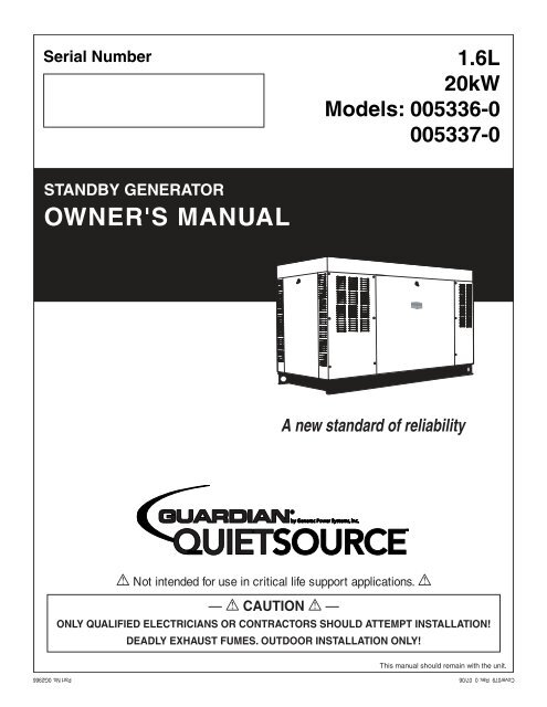
Serial Number 1.6L20kWModels: 005336-0005337-0STANDBY GENERATOROWNER'S MANUALA new standard of reliabilityNot intended for use in critical life support applications. —CAUTION—ONLY QUALIFIED ELECTRICIANS OR CONTRACTORS SHOULD ATTEMPT INSTALLATION!DEADLY EXHAUST FUMES. OUTDOOR INSTALLATION ONLY!This <strong>manual</strong> should remain with the unit.Cover079 Rev. 0 07/06 Part No. 0G2966
Standby Generator SetsTable of ContentsSECTIONPAGESAFETY RULES ................................................ 1-1INTRODUCTION .....................................................1-3Read this Manual Thoroughly ...................................1-3Operation and Maintenance ......................................1-3How to Obtain Service ..............................................1-3IDENTIFICATION RECORD .....................................2-1Data Label ................................................................2-1EQUIPMENT DESCRIPTION ...................................3-1Equipment Description ................................................3-1Engine Oil Recommendations ......................................3-1Coolant Recommendations...........................................3-1ENGINE PROTECTIVE DEVICES ............................4-1High Coolant Temperature Switch ............................4-1Low Coolant Level Sensor .........................................4-1Low Oil Pressure Switch ...........................................4-1Overcrank Shutdown ................................................4-1Overspeed Shutdown ................................................4-1RPM Sensor Loss Shutdown .....................................4-1DC Fuse ....................................................................4-1FUEL SYSTEMS .....................................................5-1Fuel Requirements ....................................................5-1Natural Gas Fuel System ..........................................5-1Propane Vapor Withdrawal Fuel System....................5-1LP Fuel System .........................................................5-1SPECIFICATIONS ...................................................6-1Generator .................................................................6-1Engine.......................................................................6-1Cooling System .........................................................6-1Fuel System ..............................................................6-1Electrical System ......................................................6-1Cold Weather Kit .......................................................6-2Reconfiguring the Fuel System ..................................6-2GENERAL INFORMATION .......................................7-1Generator AC Lead Connections ..................................7-1Four-lead, Single-phase Stator ..................................7-1Alternator Power Winding Connections ........................7-13-phase Alternators ..................................................7-1INSTALLATION .......................................................8-1Installation ...................................................................8-1Preparation Before Start-up .........................................8-1Transfer Switch ........................................................8-1Fuel System ..............................................................8-1Generator Set Lubrication ........................................8-1Prior to Initial Start-up .............................................8-1Engine Coolant .........................................................8-1Belt Tension ..............................................................8-1Electrical System ......................................................8-1Initial Inspection for QT Genset Start-up .....................8-1Start-up Checklist ........................................................8-2Preparation for Start-up............................................8-2Start-up Inspection ...................................................8-2OPERATION ...........................................................9-1Generator Control and Operation ................................9-1Operating Unit with Manual Transfer Switch ...............9-1Engine Start-up and Transfer ...................................9-1Retransfer and Shutdown .........................................9-1Operating Unit with Automatic Transfer Switch ...........9-1MAINTENANCE .....................................................10-1Maintenance Performed by AuthorizedService Facilities .....................................................10-1Every Three Months ...............................................10-1Once Every Six Months ...........................................10-1Once Annually .........................................................10-1First 100 Operating Hours ......................................10-1Every 500 Operating Hours ....................................10-1Every 800 Operating Hours ....................................10-1Exhaust Manifold Procedure ......................................10-1Intake Manifold Procedure .........................................10-1Cylinder Head Procedure ...........................................10-1Cooling System ..........................................................10-2Overload Protection for Engine DCElectrical System ....................................................10-2Checking Fluid Levels ................................................10-2Check Engine Oil ....................................................10-2Battery Fluid ...........................................................10-2Engine Coolant .......................................................10-2Maintenance Owner/Operator Can Perform ................10-3Check Engine Oil Level ...........................................10-3Check Battery .........................................................10-3Exercise System ......................................................10-3Inspect Cooling System ...........................................10-3Check Engine Coolant Level....................................10-3Perform Visual Inspection .......................................10-3Inspect Exhaust System ..........................................10-3Check Fan Belt ........................................................10-3Inspect Engine Governor ........................................10-3Changing Engine Oil ...............................................10-3Changing the Engine Air Cleaner ............................10-3Spark Plugs ............................................................10-4Coolant Change .......................................................10-4Miscellaneous Maintenance ........................................10-4Cleaning the Generator ...........................................10-4Battery ....................................................................10-4Battery Maintenance ...............................................10-4Battery Replacement ...............................................10-5SERVICE SCHEDULE ...........................................11-1TROUBLESHOOTING ...........................................12-1Troubleshooting Guide ...............................................12-1NOTESEXPLODED VIEWS & PARTS LISTSWIRING DIAGRAMS & SCHEMATICSWARRANTYContent004 Rev. 0 09/05
Standby Generator SetsImportant Safety InstructionsSAVE THESE INSTRUCTIONS – The manufacturer suggests that these rules for safeoperation be copied and posted in potential hazard areas. Safety should be stressed to alloperators, potential operators, and service and repair technicians for this equipment.Study these SAFETY RULES carefully before installing,operating or servicing this equipment. Becomefamiliar with this Owner’s Manual and with the unit.The <strong>generator</strong> can operate safely, efficiently and reliablyonly if it is properly installed, operated andmaintained. Many accidents are caused by failing tofollow simple and fundamental rules or precautions.The manufacturer cannot anticipate every possiblecircumstance that might involve a hazard. The warningsin this <strong>manual</strong>, and on tags and decals affixedto the unit are, therefore, not all inclusive. If a procedure,work method or operating technique is usedthat the manufacturer does not specifically recommend,ensure that it is safe for others. Also makesure the procedure, work method or operating techniqueutilized does not render the <strong>generator</strong> unsafe.WARNING:The engine exhaust from this productcontains chemicals known to the stateof California to cause cancer, birthdefects or other reproductive harm.WARNING:DANGERThis product contains or emits chemicalsknown to the state of California to causecancer, birth defects or other reproductive harm.Despite the safe design of this <strong>generator</strong>,operating this equipment imprudently, neglectingits maintenance or being careless can causepossible injury or death. Permit only responsibleand capable persons to install, operate or maintainthis equipment.Potentially lethal voltages are generated bythese machines. Ensure all steps are taken torender the machine safe before attempting towork on the <strong>generator</strong>.Parts of the <strong>generator</strong> are rotating and/or hotduring operation. Exercise care near running<strong>generator</strong>s.1-1 GENERAL HAZARDS • For safety reasons, the manufacturer recommendsthat this equipment be installed, serviced andrepaired by an Authorized Service Dealer or othercompetent, qualified electrician or installation technicianwho is familiar with applicable codes, standardsand regulations. The operator also mustcomply with all such codes, standards and regulations.• Installation, operation, servicing and repair of this(and related) equipment must always comply withapplicable codes, standards, laws and regulations.Adhere strictly to local, state and national electricaland building codes. Comply with regulationsthe Occupational Safety and Health Administration(OSHA) has established. Also, ensure that the<strong>generator</strong> is installed, operated and serviced inaccordance with the manufacturer’s instructionsand recommendations. Following installation, donothing that might render the unit unsafe or innoncompliance with the aforementioned codes,standards, laws and regulations.• The engine exhaust fumes contain carbon monoxidegas, which can be DEADLY. This dangerous gas,if breathed in sufficient concentrations, can causeunconsciousness or even death. For that reason,adequate ventilation must be provided. Exhaustgases must be piped safely away from any buildingor enclosure that houses the <strong>generator</strong> to an areawhere people, animals, etc., will not be harmed.This exhaust system must be installed properly, instrict compliance with applicable codes and standards.• Keep hands, feet, clothing, etc., away from drivebelts, fans, and other moving or hot parts. Neverremove any drive belt or fan guard while the unitis operating.• Adequate, unobstructed flow of cooling and ventilatingair is critical in any room or building housingthe <strong>generator</strong> to prevent buildup of explosivegases and to ensure correct <strong>generator</strong> operation.Do not alter the installation or permit even partialblockage of ventilation provisions, as this can seriouslyaffect safe operation of the <strong>generator</strong>.• Keep the area around the <strong>generator</strong> clean anduncluttered. Remove any materials that couldbecome hazardous.• When working on this equipment, remain alertat all times. Never work on the equipment whenphysically or mentally fatigued.• Inspect the <strong>generator</strong> regularly, and promptlyrepair or replace all worn, damaged or defectiveparts using only factory-approved parts.Safety 001 Rev. 0 08/05
Standby Generator SetsImportant Safety Instructions• Before performing any maintenance on the <strong>generator</strong>,disconnect its battery cables to preventaccidental start-up. Disconnect the cable from thebattery post indicated by a NEGATIVE, NEG or (–)first. Reconnect that cable last.• Never use the <strong>generator</strong> or any of its parts as astep. Stepping on the unit can stress and breakparts, and may result in dangerous operating conditionsfrom leaking exhaust gases, fuel leakage,oil leakage, etc. ELECTRICAL HAZARDS • All <strong>generator</strong>s covered by this <strong>manual</strong> producedangerous electrical voltages and can cause fatalelectrical shock. Utility power delivers extremelyhigh and dangerous voltages to the transfer switchas well as the <strong>standby</strong> <strong>generator</strong>. Avoid contactwith bare wires, terminals, connections, etc., onthe <strong>generator</strong> as well as the transfer switch, ifapplicable. Ensure all appropriate covers, guardsand barriers are in place before operating the <strong>generator</strong>.If work must be done around an operatingunit, stand on an insulated, dry surface to reduceshock hazard.• Do not handle any kind of electrical device whilestanding in water, while barefoot, or while hands orfeet are wet. DANGEROUS ELECTRICAL SHOCKMAY RESULT.• If personnel must stand on metal or concrete whileinstalling, operating, servicing, adjusting or repairingthis equipment, place insulative mats over adry wooden platform. Work on the equipment onlywhile standing on such insulative mats.• The National Electrical Code (NEC) requires theframe and external electrically conductive partsof the <strong>generator</strong> to be connected to an approvedearth ground. This grounding will help preventdangerous electrical shock that might be causedby a ground fault condition in the <strong>generator</strong> set orby static electricity. Never disconnect the groundwire.• Wire gauge sizes of electrical wiring, cables andcord sets must be adequate to handle the maximumelectrical current (ampacity) to which theywill be subjected.• Before installing or servicing this (and related)equipment, make sure that all power voltagesupplies are positively turned off at their source.Failure to do so will result in hazardous and possiblyfatal electrical shock.• Connecting this unit to an electrical system normallysupplied by an electric utility shall be bymeans of a transfer switch so as to isolate the<strong>generator</strong> electric system from the electric utilitydistribution system when the <strong>generator</strong> is operating.Failure to isolate the two electric system powersources from each other by such means will resultin damage to the <strong>generator</strong> and may also resultin injury or death to utility power workers due tobackfeed of electrical energy.Safety 001 Rev. 0 08/051-2• Generators installed with an automatic transferswitch will crank and start automatically whennormal (utility) source voltage is removed or isbelow an acceptable preset level. To prevent suchautomatic start-up and possible injury to personnel,disable the <strong>generator</strong>’s automatic start circuit(battery cables, etc.) before working on or aroundthe unit. Then, place a “Do Not Operate” tag onthe <strong>generator</strong> control panel and on the transferswitch.• In case of accident caused by electric shock, immediatelyshut down the source of electrical power.If this is not possible, attempt to free the victimfrom the live conductor. AVOID DIRECT CONTACTWITH THE VICTIM. Use a nonconducting implement,such as a dry rope or board, to free the victimfrom the live conductor. If the victim is unconscious,apply first aid and get immediate medicalhelp.• Never wear jewelry when working on this equipment.Jewelry can conduct electricity resulting inelectric shock, or may get caught in moving componentscausing injury. FIRE HAZARDS • Keep a fire extinguisher near the <strong>generator</strong> at alltimes. Do NOT use any carbon tetra-chloride typeextinguisher. Its fumes are toxic, and the liquidcan deteriorate wiring insulation. Keep the extinguisherproperly charged and be familiar with itsuse. If there are any questions pertaining to fireextinguishers, consult the local fire department. EXPLOSION HAZARDS • Properly ventilate any room or building housingthe <strong>generator</strong> to prevent build-up of explosive gas.• Do not smoke around the <strong>generator</strong>. Wipe up anyfuel or oil spills immediately. Ensure that no combustiblematerials are left in the <strong>generator</strong> compartment,or on or near the <strong>generator</strong>, as FIRE orEXPLOSION may result. Keep the area surroundingthe <strong>generator</strong> clean and free from debris.• These <strong>generator</strong> sets may operate using one ofseveral types of fuels. All fuel types are potentiallyFLAMMABLE and/or EXPLOSIVE and should behandled with care. Comply with all laws regulatingthe storage and handling of fuels. Inspect theunit’s fuel system frequently and correct any leaksimmediately. Fuel supply lines must be properlyinstalled, purged and leak tested according toapplicable fuel-gas codes before placing this equipmentinto service.• Diesel fuels are highly FLAMMABLE. Gaseousfluids such as natural gas and liquid propane(LP) gas are extremely EXPLOSIVE. Natural gasis lighter than air, and LP gas is heavier than air;install leak detectors accordingly.
Standby Generator SetsImportant Safety InstructionsINTRODUCTIONThank you for purchasing this model of the <strong>standby</strong><strong>generator</strong> set product line.Every effort was expended to make sure that theinformation and instructions in this <strong>manual</strong> wereboth accurate and current at the time the <strong>manual</strong> waswritten. However, the manufacturer reserves the rightto change, alter or otherwise improve this product(s)at any time without prior notice. READ THIS MANUAL THOROUGHLYIf any portion of this <strong>manual</strong> is not understood, contactthe nearest Authorized Service Dealer for starting,operating and servicing procedures.Throughout this publication, and on tags anddecals affixed to the <strong>generator</strong>, DANGER, WARNING,CAUTION and NOTE blocks are used to alert personnelto special instructions about a particular serviceor operation that may be hazardous if performedincorrectly or carelessly. Observe them carefully.Their definitions are as follows:DANGERAfter this heading, read instructions that, if notstrictly complied with, will result in personal injuryor property damage.After this heading, read instructions that, if notstrictly complied with, may result in personalinjury or property damage.After this heading, read instructions that, if notstrictly complied with, could result in damage toequipment and/or property.NOTE:After this heading, read explanatory statementsthat require special emphasis.These safety warnings cannot eliminate the hazardsthat they indicate. Common sense and strict compliancewith the special instructions while performingthe service are essential to preventing accidents.Four commonly used safety symbols accompany theDANGER, WARNING and CAUTION blocks. The typeof information each indicates is as follows:This symbol points out important safety informationthat, if not followed, could endangerpersonal safety and/or property of others.This symbol points out potential explosionhazard.This symbol points out potential fire hazard.This symbol points out potential electrical shockhazard.The operator is responsible for proper and safe useof the equipment. The manufacturer strongly recommendsthat the operator read this Owner's Manualand thoroughly understand all instructions beforeusing this equipment. The manufacturer also stronglyrecommends instructing other users to properlystart and operate the unit. This prepares them if theyneed to operate the equipment in an emergency. OPERATION AND MAINTENANCEIt is the operator's responsibility to perform all safetychecks, to make sure that all maintenance for safeoperation is performed promptly, and to have theequipment checked periodically by an AuthorizedService Dealer. Normal maintenance service andreplacement of parts are the responsibility of theowner/operator and, as such, are not considereddefects in materials or workmanship within the termsof the warranty. Individual operating habits and usagecontribute to the need for maintenance service.Proper maintenance and care of the <strong>generator</strong> ensurea minimum number of problems and keep operatingexpenses at a minimum. See an Authorized ServiceDealer for service aids and accessories.Operating instructions presented in this <strong>manual</strong>assume that the <strong>standby</strong> electric system has beeninstalled by an Authorized Service Dealer or othercompetent, qualified contractor. Installation of thisequipment is not a “do-it-yourself” project. HOW TO OBTAIN SERVICEWhen the <strong>generator</strong> requires servicing or repairs,simply contact an Authorized Service Dealer forassistance. Service technicians are factory-trainedand are capable of handling all service needs.When contacting an Authorized Service Dealer or thefactory about parts and service, always supply thecomplete model number of the unit as given on thefront cover of this <strong>manual</strong> or on the DATA LABELaffixed to the unit.AUTHORIZED SERVICE DEALER LOCATIONTo locate the nearest AUTHORIZEDSERVICE DEALER, please call this number:1-800-333-1322or locate us on the web at:www.generac.com1-3Safety 001 Rev. 0 08/05
Standby Generator SetsGeneral InformationIDENTIFICATION RECORDDATA LABELEvery <strong>generator</strong> set has a DATA LABEL that containsimportant information pertinent to the <strong>generator</strong>. Thedata label, which can be found attached to the <strong>generator</strong>’slower connection box, lists the unit’s serialnumber and its rated voltage, amps, wattage capacity,phase, frequency, rpm, power factor, etc.NOTE:For actual information related to this particularmodel, please refer to the Manual Drawing Listinglocated at the end of this <strong>manual</strong>, or to the datalabel affixed to the unit. Generator Model and Serial NumberThis number is the key to numerous engineering andmanufacturing details pertaining to your unit. Alwayssupply this number when requesting service, orderingparts or seeking information.Data LabelGENERATOR SET DATAMADE IN USAMODELRATED KWRATED VOLTAGERATED KVASERIALRATED AMPSPHASEPOWER FACTORHERTZALT RPMENGINE RPMPRODUCTION DATEALTERNATOR SUBTRANSIENT REACTANCEALTERNATOR TRANSIENT REACTANCECLASSROTOR STATOR WINDING INSULATION AT 25°C AMBIENTGENERAC POWER SYSTEMS, INC.WAUKESHA, WI2-1Identy 002 Rev. B 05/06
Standby Generator SetsEquipment DescriptionEQUIPMENT DESCRIPTIONThis equipment is a revolving field, alternating current<strong>generator</strong> set. It is powered by a gaseous fueledengine operating at 1800 rpm for 4-pole direct driveunits, 3600 rpm for 2-pole direct drive units and2300 - 3000 rpm for quiet drive gear units. See theSpecifications section for exact numbers. The unitcomes complete with a sound attenuated enclosure,internally mounted muffler, control console, mainlinecircuit breaker, battery charger, and protectivealarms as explained in the following paragraph.All AC connections, including the power leads fromthe alternator, 120 volt battery charger input andcontrol connections to the transfer switch are availablein the main connection box.The <strong>generator</strong> incorporates the following <strong>generator</strong>features:• Rotor and Stator insulation is Class F rated asdefined by NEMA MG1-32.6, NEMA MG1-1.66.The <strong>generator</strong> is self ventilated and drip-proof constructed.• The voltage waveform deviation, total harmoniccontent of the AC waveform and telephone influencefactor have been evaluated and are acceptableaccording to NEMA MG1-32.ENGINE OIL RECOMMENDATIONSThe unit has been filled with 15W-40 engine oil atthe factory. Use a high-quality detergent oil classified“For Service CC, SD, SE, SF.” Detergent oils keep theengine cleaner and reduce carbon deposits. Use oilhaving the following SAE viscosity rating, based onthe ambient temperature range anticipated before thenext oil change:TemperatureOil Grade (Recommended)Above 80° F (27° C) SAE 30W or 15W-4032° to 80° F (0° to 27° C) SAE 20W-20 or 15W-40Below 32° F (0° C)See NoteCOOLANT RECOMMENDATIONSUse a mixture of half low silicate ethylene glycolbase anti-freeze and deionized water. Cooling systemcapacity is listed in the specifications. Use only deionizedwater and only low silicate anti-freeze. If desired,add a high quality rust inhibitor to the recommendedcoolant mixture. When adding coolant, always addthe recommended 50-50 mixture.Do not use any chromate base rust inhibitorwith ethylene glycol base anti-freeze or chromiumhydroxide (“green slime”) forms and willcause overheating. Engines that have been operatedwith a chromate base rust inhibitor mustbe chemically cleaned before adding ethyleneglycol base anti-freeze. Using any high silicateanti-freeze boosters or additives will also causeoverheating. The manufacturer also recommendsthat any soluble oil inhibitor is NOT used for thisequipment.DANGERDo not remove the radiator pressure cap whilethe engine is hot or serious burns from boilingliquid or steam could result.Ethylene glycol base antifreeze is poisonous.Do not use mouth to siphon coolant from theradiator, recovery bottle or any container. Washhands thoroughly after handling. Never storeused antifreeze in an open container becauseanimals are attracted to the smell and taste ofantifreeze even though it is poisonous to them.Any attempt to crank or start the engine beforeit has been properly serviced with the recommendedoil may result in an engine failure.NOTE:For temperatures below 32° F, it is strongly recommendedto use the optional Cold Weather Start Kit(part number listed in the Specification Section).The oil grade for temperatures below 32° F is 5W-30 synthetic oil.3-1Equip002 Rev. 0 08/05
Standby Generator SetsEngine Protective DevicesENGINE PROTECTIVE DEVICESThe <strong>standby</strong> <strong>generator</strong> may be required to operate forlong periods of time without an operator on hand tomonitor such engine conditions as coolant temperature,oil pressure or rpm. For that reason, the enginehas several devices designed to protect it againstpotentially damaging conditions by automaticallyshutting down the unit when the oil pressure is toolow, the coolant temperature is too high, the coolantlevel is too low, or the engine is running too fast.NOTE:Engine protective switches and sensors are mentionedhere for the reader’s convenience. Alsorefer to the applicable control panel <strong>manual</strong> foradditional automatic engine shutdown information. HIGH COOLANT TEMPERATURE SWITCHThis switches contacts close if the temperature shouldexceed approximately 140° C (284° F), initiating anengine shutdown. The <strong>generator</strong> will automaticallyrestart and the LED will reset once the temperaturehas returned to a safe operating level. LOW COOLANT LEVEL SENSORShould the engine coolant level drop below the levelof the high coolant temperature switch, it is possiblefor the engine to overheat without automatic shutdown.To prevent such overheating, the engine has alow coolant level sensor. If the level of engine coolantdrops below the level of the low coolant level sensor,the engine automatically shuts down. LOW OIL PRESSURE SWITCHThis switch has normally closed contacts that areheld open by engine oil pressure during cranking andoperating. Should oil pressure drop below the 8 psirange, switch contacts close, and the engine shutsdown. The unit should not be restarted until oil isadded, and the AUTO/OFF/MANUAL switch must beturned to OFF and then back to AUTO.OVERCRANK SHUTDOWNAfter a prespecified duration of cranking, this functionends the cranking if the engine has failed tostart. The overcrank LED will turn ON. Turn OFF theAUTO/OFF/MANUAL switch, then turn switch back toAUTO to reset the <strong>generator</strong> control board.NOTE:If the fault is not corrected, the overcrank featurewill continue to activate.Approximate Crank Cycle Times• 15 seconds ON• 7 seconds OFF• 7 seconds ON• 7 seconds OFF• Repeat for 45 secondsApproximately 90 seconds total. OVERSPEED SHUTDOWNA speed circuit controls engine cranking, start-up,operation and shutdown. Engine speed signals aredelivered to the circuit board whenever the unit isrunning. Should the engine overspeed above a safe,preset value, the circuit board initiates an automaticengine shutdown. Contact the nearest AuthorizedDealer if this failure occurs. RPM SENSOR LOSS SHUTDOWNIf the speed signal to the control panel is lost, engineshutdown will occur. DC FUSEThis fuse is located inside of the control panel. Itprotects the panel wiring and components fromdamaging overload. Always remove this fuse beforecommencing work on the <strong>generator</strong>. The unit willnot start or crank if the fuse is blown. Replace thefuse with one of the same size, type, and rating. (Seethe exploded views and parts lists at the end of this<strong>manual</strong> for replacement part number.)4-1EngProt001 Rev. 0 08/05
Standby Generator SetsFuel SystemsFUEL SYSTEMFUEL REQUIREMENTSThe <strong>standby</strong> <strong>generator</strong> may be equipped with one ofthe following fuel systems:• Natural gas fuel system• Propane vapor (PV) fuel systemThe Manual Drawing Listing that is affixed to theunit includes the “Identification Code,” which may beused to identify the type of fuel system installed onthe unit.Recommended fuels should have a Btu content of atleast 1,000 Btus per cubic foot for natural gas; or atleast 2,520 Btus per cubic foot for LP gas. Ask thefuel supplier for the Btu content of the fuel.Required fuel pressure for natural gas is 5 inchesto 14 inches water column (0.18 to 0.5 psi); andfor liquid propane, 5 inches to 14 inches of watercolumn (0.18 to 0.5 psi).NOTE:Any piping used to connect the <strong>generator</strong> to thefuel supply should be of adequate size to ensurethe fuel pressure NEVER drops below five incheswater column for natural gas or 5 inches watercolumn for propane vapor for all load ranges.NOTE:It is the responsibility of the installer to make surethat only the correct recommended fuel is suppliedto the <strong>generator</strong> fuel system. Thereafter, theowner/operator must make certain that only theproper fuel is supplied. NATURAL GAS FUEL SYSTEMNatural gas is supplied in its vapor state. In mostcases, the gas distribution company provides pipingfrom the main gas distribution line to the <strong>standby</strong><strong>generator</strong> site. The following information applies tonatural gas fuel systems.• Gas pressure in a building is usually regulated bynational, state and local codes.• To reduce gas pressure to a safe level beforethe gas enters a building, a primary regulator isneeded. The natural gas supplier may or may notsupply such a regulator.• It is the responsibility of the gas supplier to makesure sufficient gas pressure is available to operatethe primary regulator.• Gas pressure at the inlet to the fuel shutoff solenoidshould not exceed approximately 14 incheswater column (0.5 psi). Optimum pressure at thefuel shutoff solenoid is 11 inches water column(0.4 psi).PROPANE VAPOR WITHDRAWAL FUEL SYSTEMThis type of system utilizes the vapors formed abovethe liquid fuel in the supply tank. Approximately 10to 20 percent of the tank capacity is needed for fuelexpansion from the liquid to the vapor state. Thevapor withdrawal system is generally best suited forsmaller engines that require less fuel. The installershould be aware of the following:• The natural gas and LP gas systems are similar.However, the natural gas system delivers gas at apressure of approximately five inches water columnto the carburetor.• When ambient temperatures are low and enginefuel consumption is high, the vapor withdrawalsystem may not function efficiently.• Ambient temperatures around the supply tankmust be high enough to sustain adequate vaporization,or the system will not deliver the needed fuelvolume.• In addition to the cooling effects of ambient air, thevaporization process itself provides an additionalcooling effect. LP FUEL SYSTEMLP is supplied as a liquid in pressure tanks. It isusually made up of propane, butane, or a mixture ofthe two gases. Propane tends to vaporize readily evenat temperatures as low as -20° F (-29° C). However,butane reverts to its liquid state when temperaturesdrop below 32° F (0° C).LP in a liquid withdrawal system must be convertedto its gaseous state before it is introduced into theengine carburetor. A vaporizer-converter is generallyused to accomplish this. In such a converter, heatedengine coolant is ported through the converter toprovide the necessary heat for conversion of the fuelfrom a liquid to a gaseous state.5-1FuelSys001 Rev. 0 08/05
Standby Generator SetsSpecificationsSPECIFICATIONSGENERATORType ............................................................................. SynchronousRotor Insulation ....................................................................Class FStator Insulation ...................................................................Class FTotal Harmonic Distortion .........................................................< 5%Alternator Output Leads 3-phase ........................................... 4-wireBearings .........................................................................Sealed BallCoupling .......................................................................Flexible DiscLoad Capacity (Standby Rating) ............................................20kW** NOTE: Generator rating and performance in accordance with ISO8528-5, BS5514, SAE J1349,ISO3046 and DIN 6271 Standards. KW rating is based on LPG fuel and may derate with naturalgas.Excitation System ....................................................................DirectGenerator Output Voltage/kW - 60 Hz kW Amp CB Size120/240V, 1-phase, 1.0 pf 20 83 100120/208V, 3-phase, 0.8 pf 20 69 80Generator Locked Rotor KVA Available @ Voltage Dip of 35%Single-phase or 208 3-phase ............................................. 30 KVA ENGINEMake ................................................................................... GeneracModel ..................................................................................... In LineCylinders and Arrangement ............................................................ 4Displacement .......................................................................1.6 LiterBore ...................................................................................... 3.15 in.Stroke ................................................................................... 3.13 in.Compression Ratio .............................................................9.75-to-1Air Intake System ...............................................Naturally AspiratedValve Seats ................................................................... ReplaceableLifter Type .......................................................................... HydraulicEngine ParametersRated Synchronous RPM ..............................................60 Hz, 3600HP at rated kW .......................................................................35 HPExhaust SystemExhaust Flow at Rated Output 60 Hz .................................. 177 cfmExhaust Temperature at Rated Output .................................. 910° FCombustion Air Requirements (Natural Gas)Flow at rated power, 60 Hz ................................................... 80 cfmGovernorType .................................................................................. ElectronicFrequency Regulation ...................................................IsochronousSteady State Regulation ........................................................± .25%Adjustments:Speed ............................................................................ SelectableEngine Lubrication SystemType of Oil Pump ...................................................................... GearOil Filter .............................................................Full Flow, CartridgeCrankcase Oil Capacity ....................................................4 U.S. qts. COOLING SYSTEMType .......................................................................................ClosedWater Pump .................................................................... Belt DrivenFan Speed ................................................................................ 2550Fan Diameter .....................................................................16 inchesFan Mode ..............................................................................PusherAir Flow (inlet air including alternator andcombustion air) .......................................................... 1528 ft3/min.Coolant Capacity ...........................................................2.0 U.S. gal.Heat Rejection to Coolant ..........................................107,000 Btu/hMaximum Operating Air Temp. on Radiator ..............60° C (150° F)Maximum Ambient Temperature ................................50° C (140° F) FUEL SYSTEMType of Fuel .........................................Natural Gas, Propane VaporCarburetor ...................................................................... Down DraftSecondary Fuel Regulator .................................................StandardFuel Shut-off Solenoid ........................................................StandardOperating Fuel Pressure ...................... 5 in. - 14 in. Water ColumnFuel Consumption - ft 3 /hr (Natural Gas/LPV)Exercise 25% 50% 75% 100%Cycle Load Load Load Load59/23 124/49 188/75 250/99 315/125ELECTRICAL SYSTEMBattery Charge Alternator ............................................12V, 15 AmpStatic Battery Charger ............................................................2 AmpRecommended Battery ...................................... Group 26, 525CCASystem Voltage .....................................................................12 VoltsVoltage RegulatorType .................................................................................. ElectronicSensing ........................................................................ Single-phaseRegulation ................................................................................± 1%Features ................................................. V/F Adjustable, AdjustableVoltage and Gain LED IndicatorsPower Adjustment for Ambient ConditionsTemperature Deration3% for every 10° C above °C ..................................................... 401.65% for every 10° above °F .................................................. 104Altitude Deration1% for every 100 m above m ................................................... 9143% for every 1000 ft. above ft. ............................................... 3000Controller .................................................R-2006-1GenSpec030 Rev. 0 05/06
Standby Generator SetsSpecificationsFigure 1 — InterconnectionsCONTROL PANELTransfer SwitchUtility InNEUTRALTOALTERNATORGENERATORCONNECTIONBOX120 Volt +NeutralGrdN1N223194183178BatteryChargerInputCIRCUITBREAKERGROUNDNEUTRAL4- # 14 GAWIRES TOGENERATORCONNECTIONBOXGenN1N223194186178LoadOutTO GENERATORCONNECTION BOXTo Generator Control PanelFRAME RAILGround LevelConcrete SlabSTUB-UP AREASee Install Dwg forDimensionsCIRCUIT BREAKER SIZEKW VOLTS / AMPS LUG SIZE25 240 1 Ø 125 #4 to 1/025 208 3 Ø 100 #4 to 1/0 COLD WEATHER KITFor cold climates, optional cold weather kit (partnumber 0F6148) is recommended. The kit includes:• Battery Warmer• 4” Junction Box with hardware• 6 qt. pack 5W-30 synthetic oil (engine) RECONFIGURING THE FUEL SYSTEMNOTE:All models are configured for natural gas or LPvapor from the factory.To reconfigure the fuel system from NG to LP, followthese steps:1. Turn the main gas supply off.2. Remove the carburetor fuel hose from the outletport (Port 1) of the demand regulator (Figure6.2).3. Remove the brass hose fitting from the outlet port(Port 1) of the demand regulator.4. Remove pipe plug from Port 2.5. Install brass hose fitting into Port 2.6. Install pipe plug into Port 1.7. Connect carburetor gas hose to brass fitting.8. Tighten all clamps and plugs.9. Make sure fuel supply is of the proper pressureand type for configuration.GenSpec030 Rev. 0 05/066-210. Reverse the procedure to convert back to naturalgas.11. The Dip switch inside the control panel must bein the LP or NG position when switching to differentfuels.PLUGFigure 6.2 — Reconfigure the Fuel SystemPort 1 Port 2NG FUEL SYSTEMFUEL HOSEBRASS HOSEFITTINGOUTPORT 1HOUSINGPORTSFUEL HOSEBRASS HOSEFITTINGOUTPORT 2HOUSINGPORTSLP FUEL SYSTEMNOTE:Port 1 is for NG only and Port 2 is for LP vaporonly. No provision for dual fuel has been made.DANGERSerious injury or damage may occur if not configuredproperly. Please consult an AuthorizedDealer with any questions.PLUG
Standby Generator SetsGeneral InformationGENERATOR AC LEAD CONNECTIONSSee “Voltage Codes”. This <strong>generator</strong> may be ratedat any one of three voltages, either single-phase orthree-phase. The electrical wires in the unit’s AC connection(lower) panel should be installed according tothe number of leads and the voltage/phase requiredfor the application. If there are any questions regardinglead connection, refer to the wiring diagrams atthe back of this <strong>manual</strong>.Voltage codes apply to the type of stator assemblyinstalled on a particular <strong>generator</strong>. FOUR-LEAD, SINGLE-PHASE STATORFour-lead <strong>generator</strong>s (see Figure 7.1) are designed tosupply electrical loads with voltage code “A” (240V,1-phase, 60 Hz). Electrical power is produced in thestator power windings. These windings were connectedat the factory to the main circuit breaker asshown in Figure 7.1.The rated voltage between each circuit breaker terminalis 240V. The rated voltage between each circuitbreaker terminal and the neutral point 00 is 120V.Figure 7.1 — Four-lead, Single-phase StatorALTERNATOR POWER WINDINGCONNECTIONS 3-PHASE ALTERNATORSThe <strong>generator</strong> is designed to supply 3-phase electricalloads. Electric power is produced in the alternatorpower windings. These windings were connectedat the factory to the main circuit breaker with a “Y”configuration as shown in Figures 7.2 and 7.3.The rated voltage between circuit breaker terminalsE1-E2, E1-E3 and E2-E3 is either 480V or 208Vdepending on the model.The rated voltage between each circuit breaker terminaland the neutral point 00 is either 277V or 120Vdepending on the model.Figure 7.2 — Stator Power WindingConnections - 3-phase, 277/480V (6 Lead)INTERNALCONNECTIONSS1 E1S6S4NEUTRALL-LS5E3 S3L-NS2E2Figure 7.3 — Stator Power WindingConnections - 3-phase, 120/208V (6 Lead)E1S1S1S4S6S4S500 (NEUTRAL)L-LS3S6S5S2E3S3L-NS2E27-1ACConn001 Rev. 0 08/05
Standby Generator SetsInstallationINSTALLATIONRefer to the separate “Installation Guide QT ProductLine” supplied with the unit.PREPARATION BEFORE START-UPThe instructions in this section assume that the<strong>standby</strong> <strong>generator</strong> has been properly installed, serviced,tested, adjusted and otherwise prepared foruse by a competent, qualified installation contractor.Be sure to read the “Safety Rules”, as well as all othersafety information in this <strong>manual</strong>, before attemptingto operate this (and related) equipment.Before starting the <strong>generator</strong> for the first time, theinstaller must complete the following procedures. Forfollow-up maintenance information and/or serviceintervals, please refer to the “Maintenance” sectionand the “Service Schedule”. TRANSFER SWITCHIf this <strong>generator</strong> is used to supply power to any electricalsystem normally powered by an electric utility,the National Electrical Code requires that a transferswitch be installed. The transfer switch prevents electricalbackfeed between two different electrical systems.(For additional information, see the applicabletransfer switch <strong>manual</strong> for this unit.) The transferswitch, as well as the <strong>generator</strong> and other <strong>standby</strong>components, must be properly located and mountedin strict compliance with applicable codes, standardsand regulations. FUEL SYSTEMMake sure the fuel supply system to the <strong>generator</strong>(a) delivers the correct fuel at the correct pressureand (b) is properly purged and leak testedaccording to code. No fuel leakage is permitted. See“Specifications” for more information.GENERATOR SET LUBRICATIONCheck the engine crankcase oil level before operatingand add oil to the proper level – the dipstick “FULL”mark. Never operate the engine with the oil levelbelow the dipstick “ADD” mark. See “Specifications”and “Engine Oil Recommendations”.NOTE:This engine is shipped from the manufacturerwith “break-in” oil. This oil should be changedafter 30 hours of operation.Check the oil level in the <strong>generator</strong> gearbox (if soequipped) prior to initial use and at the intervalsindicated by the “Service Schedule.” The recommendedoil is SAE 90 gear lubricant.Also, if the engine is equipped with a mechanical governor,make sure the governor is properly lubricatedwith clean engine oil.8-1PRIOR TO INITIAL START-UPPrior to initially starting the <strong>generator</strong>, it mustbe properly prepared for use. Any attempt tocrank or start the engine before it has beenproperly serviced with the recommended typesand quantities of engine fluids (oil, coolant, fuel,etc.) may result in an engine failure. ENGINE COOLANTHave the engine cooling system properly filled withthe recommended coolant mixture. Check the systemfor leaks and other problems. See “Specifications”and “Coolant” sections. BELT TENSIONCheck-the engine-fan belt tension and condition priorto placing the unit into service and at recommendedintervals. Belt tension is correct when a force ofapproximately 22 pounds (10 kg), applied midwaybetween pulleys, deflects the belt about 3/8- to 5/8-inch (10 to 16 mm).ELECTRICAL SYSTEMMake sure the <strong>generator</strong> is properly connected to anapproved earth ground.Make sure the <strong>generator</strong> battery is fully charged,properly installed and interconnected, and ready foruse.Check to ensure that there are no loose electrical connections.Restrain any loose wires to keep them clearof any moving <strong>generator</strong> set components.INITIAL INSPECTION FOR QT GENSETSTARTUPInspect for the following.• Freight Damage.• Manuals present.• Fluid Levels (Oil, coolant, battery, Gear Drive).• Correct fuel piping.• Correct muffler installation for external application.• Adequate air flow, clearances and ventilation perinstallation drawings and applicable codes.• Correct AC and DC wire size, connections andgrounding. Control and communication wiring to/from the transfer switch must be run in a separateconduit from the AC power leads.• Battery charger connection to 120 VAC.• Communication wires connected between transferswitch and <strong>generator</strong> (HTS only).• Unit secured to pad.Install001 Rev. C 05/06
Standby Generator SetsInstallationSTART-UP CHECKLISTBefore working on the <strong>generator</strong>, ensure the following:• The AUTO/OFF/MANUAL switch is in the OFFposition.• The 120VAC supply to the battery charger isswitched OFF. PREPARATION FOR START-UP• Ensure that the 120VAC circuit breaker to the batterycharger is open.• Remove the fuse from the the control panel. Forthe H-100 and R-series: Open the front door of thecontrol box and remove the 15 Amp ATO fuse inthe lower left-hand corner of the control box.• Connect the battery cables to the battery. Attachnegative battery cable last.• Close the 120VAC circuit breaker to the batterycharger.• Measure the voltage at the battery before and afterthe charger is turned on.• Verify all AC electrical connections are tight at thecircuit breaker and transfer switch.• Visually inspect entire area looking for loose paper,plastic wrappings, leaves, etc.• Check all hoses clamps fittings for leaks or damage.• Check all electrical plugs throughout the <strong>generator</strong>.Ensure each plug is seated correctly and fullyinserted into its receptacle.• Verify the AUTO/OFF/MANUAL switch is in OFFposition.• Open the valve to the engine fuel line.• Bleed the fuel system of air. (necessary for long fuellines).• Open the <strong>generator</strong> main line circuit breaker.• Connect a manometer to the gas line and recordthe static pressure. It must be as listed in theSpecifications.• Insert the fuse into the control panel.• Move the AUTO/OFF/MANUAL switch to the MAN-UAL position. The engine should now crank andstart.• Check voltage at the <strong>generator</strong> terminals.• For 3-phase units, check phase rotation at thetransfer switch terminals. The <strong>generator</strong> phaserotation must match the utility phase rotation.• Check for coolant, fuel, oil, and exhaust leaks.• Close the <strong>generator</strong>s main line circuit breaker.• Turn the <strong>generator</strong> set off.• Connect the UTILITY supply to the transferswitch.• Set the AUTO/OFF/MANUAL switch to AUTO.• Disconnect utility power before the transferswitch.Engine should start, transfer to load.Run at least 15 minutes on <strong>generator</strong> power.Make certain all 3-phase loads are functioningcorrectly (correct phase rotation).• Reconnect Utility powerTransfer switch will transfer back to Utility andengine will shut down within the given timeparameters set up for the specific transfer switchand controller.• Install all covers, access plates and door panels.• Put the Owners Manual in a safe and accessibleplace.• Make certain the AUTO/OFF/MANUAL switch is inthe AUTO position. START-UP INSPECTIONWhen a start-up is performed by an AuthorizedService Dealer, a standard three-part form titled“Start-up Inspection for Standby Power Systems”(part no. 067377), should be completed by the installationtechnician or engineer. See page 1-3 for informationon locating the nearest Authorized ServiceDealer. The installer should complete the form anddisseminate copies as follows:• White copy: Mail to Generac Warranty Department,P.O. Box 340, 211 Murphy Dr., Eagle, WI 53119-2062.• Pink Copy: For service file of installing dealer.• Yellow Copy: For the customer’s records.Install001 Rev. C 05/068-2
Standby Generator SetsOperationGENERATOR CONTROL ANDOPERATIONRefer to the appropriate control panel operator’s<strong>manual</strong> for this unit.OPERATING UNIT WITH MANUALTRANSFER SWITCHIf the <strong>generator</strong> was installed in conjunction with atransfer switch capable of <strong>manual</strong> operation only, thefollowing procedure applies. A <strong>manual</strong>ly operatedtransfer switch is one that will not provide automaticstart-up and does not include an intelligence circuit. ENGINE START-UP AND TRANSFERFor additional information, refer to the applicablecontrol panel <strong>manual</strong> for this unit, as well as any literaturepertaining to the specific transfer switch.DANGERThe Maintenance Disconnect Switch and theAUTO/OFF/MANUAL switches (if so equipped)must be set properly, or the <strong>generator</strong> will crankand start as soon as the utility power to thetransfer switch is turned off. Refer to applicablecontrol panel and transfer switch <strong>manual</strong>s formore information.Do not proceed until certain that utility sourcevoltage is available to the transfer switch andthe transfer switch main contacts are set toUTILITY.Do not attempt <strong>manual</strong> operation until all powersupplies to the transfer switch have been positivelyturned off, or extremely dangerous - possiblylethal - electrical shock will result.Transfer switch enclosure doors should be keptclosed and locked. Only authorized personnelshould be allowed access to the transfer switchinterior. Extremely high and dangerous voltagesare present in the transfer switch.In order to transfer load from the utility source to the<strong>generator</strong>, follow these directions:• Turn OFF or disconnect the utility power circuitto the transfer switch, using the means provided(such as the utility source main line circuit breaker).• Set the transfer handle to its UTILITY (NORMAL)position with load circuits connected to the utilitypower supply.• Set the <strong>standby</strong> <strong>generator</strong>’s main line circuit breakerto its OFF (or OPEN) position.• Start the <strong>generator</strong>.Do not crank the engine continuously for longerthan 30 seconds, or the heat maydamage the starter motor.• Let engine stabilize and warm up.• Check all applicable instrument and gauge readings.When certain that all readings are correct,move the transfer switch <strong>manual</strong> handle to itsSTANDBY (GENERATOR) position, i.e., load circuitssupplied by the <strong>generator</strong>.• Set the <strong>standby</strong> <strong>generator</strong>’s main line circuit breakerto its ON (or CLOSED) position.• Load circuits are now powered by the <strong>standby</strong><strong>generator</strong>. RETRANSFER AND SHUTDOWNFor additional information, refer to the applicablecontrol panel <strong>manual</strong> for this unit, as well as any literaturepertaining to the specific transfer switch.To transfer the load back to the utility power sourceand shut down the <strong>generator</strong>, follow these directions:• Set the <strong>standby</strong> <strong>generator</strong>’s main line circuit breakerto its OFF (or OPEN) position.• Manually move the transfer switch handle to itsUTILITY (NORMAL) position, i.e., load circuitsconnected to the utility.• Turn ON the utility power supply to the transferswitch, using the means provided (such as the utilitypower source main line circuit breaker).• Let the <strong>generator</strong> run at no-load for a few minutesto stabilize internal temperatures.• Shut down the <strong>generator</strong>.OPERATING UNIT WITH AUTOMATICTRANSFER SWITCHIf the <strong>generator</strong> has been installed with an automatictransfer switch, such as an RTS, HTS, or GTS-typetransfer switch, the engine may be started andstopped automatically or <strong>manual</strong>ly.NOTE:Refer to the applicable <strong>manual</strong> for your transferswitch and to “Transfer Switch Start SignalConnections”. In addition, please note the dangersunder “Engine Start-up and Transfer.”9-1Oper001 Rev. 0 08/05
Standby Generator SetsMaintenanceMAINTENANCE PERFORMED BYSERVICE FACILITIESBefore working on the <strong>generator</strong>, ensure the following:• The AUTO/OFF/MANUAL switch is in the OFFposition.• The 15A fuse has been removed from the controlbox.• The 120VAC supply to the battery charger isswitched OFF. EVERY THREE MONTHS1. Check battery condition.2. Inspect and test fuel system.3. Check transfer switch.4. Inspect exhaust system.5. Check engine ignition system.6. Check fan belts. ONCE EVERY SIX MONTHS1. Test Engine Safety Devices (low oil pressure, lowcoolant level, high coolant temperature). ONCE ANNUALLY1. Test engine governor; adjust or repair, if needed.2. Clean, inspect <strong>generator</strong>.3. Flush cooling system. FIRST 30 OPERATING HOURS1. Change engine "break-in" oil and filter. FIRST 100 OPERATING HOURS1. Change engine oil and oil filter. After initialchange, service engine oil and filter at 100 operatinghours or six months, whichever comes first.2. Retorque cylinder head.3. Retorque intake and exhaust manifold. EVERY 500 OPERATING HOURS1. Service air cleaner.2. Check starter.3. Check engine DC alternator.COOLING SYSTEMAir intake and outlet openings in the <strong>generator</strong> compartmentmust be open and unobstructed for continuedproper operation. This includes such obstructionsas high grass, weeds, brush, leaves and snow.Without sufficient cooling and ventilating air flow, theengine/<strong>generator</strong> quickly overheats, which causes itto shut down. (See the installation diagram.)The exhaust system parts from this product getextremely hot and remains hot after shutdown.High grass, weeds, brush, leaves, etc. mustremain clear of the exhaust. Such materials mayignite and burn from the heat of the exhaustsystem.OVERLOAD PROTECTION FOR ENGINEDC ELECTRICAL SYSTEMEngine cranking, start up and running are controlledby a solid state Engine Controller circuit board.Battery voltage is delivered to that circuit board viaa 15 amp fuse. These overcurrent protection deviceswill open if the circuit is overloaded.If a circuit breaker opens or a fuse elementmelts, find the cause of the overload beforeresetting the circuit breaker or replacing thefuse.CHECKING FLUID LEVELS CHECK ENGINE OILCheck engine crankcase oil level (Figure 10.1) at leastevery 20 hours of operation, or prior to use.• Remove oil dipstick and wipe dry with a clean, lintfreecloth.• Install oil dipstick, then remove again.• Oil should be between FULL and ADD marks.• If oil level is below the dipstick ADD mark, removeoil fill cap-. Add the recommended oil to bring oillevel up to the FULL mark. DO NOT FILL ABOVETHE “FULL” MARK. See “Engine Oil Recommendations”for recommended oils. EVERY 800 OPERATING HOURS1. Retorque cylinder head.2. Retorque intake and exhaust manifold.3. Check engine compression.4. Check valve clearance.10-1Maint011 Rev. B 05/06
Standby Generator SetsMaintenanceFigure 10.1 - Oil Dipstick and Oil Fill CapOIL FILL CAPEXERCISE SYSTEMStart the <strong>generator</strong> engine at least once every sevendays and let it run at least 20 minutes. See “WeeklyExercise Cycle”.INSPECT COOLING SYSTEM• Inspect engine cooling system. See “MaintenanceSchedule”.• Check hoses for damage, deterioration, leaks, etc.Correct any discrepancies found.• Check hose clamps for tightness.OILDIPSTICK CHECK ENGINE COOLANT LEVELSee “Checking Fluid Levels”. BATTERY FLUIDCheck battery electrolyte fluid based on theMaintenance Schedule. Fluid should cover separatorsin all battery cells. If fluid level is low, add distilledwater to cover tops of separators. DO NOT USETAP WATER IN BATTERY. ENGINE COOLANTCheck coolant level in coolant recovery bottle. SeeSpecifications.• Add recommended coolant mixture as necessary.• Periodically remove radiator pressure cap (onlywhen engine has cooled down) to make sure thecoolant recovery system is functioning properly.Coolant should be at bottom of radiator filler neck.If coolant level is low, inspect gasket in radiatorpressure cap. Replace cap, if necessary. To havepressure cap tested, contact a Service Dealer.Inspect cooling system and coolant recovery systemfor leaks.MAINTENANCE OWNER/OPERATOR CAN PERFORM CHECK ENGINE OIL LEVELRefer to “Checking Fluid Levels”. CHECK BATTERY• See “Checking Fluid Levels”.• Check battery cables for condition, tightness, corrosionor damage. Clean, tighten or replace asnecessary.Maint011 Rev. B 05/0610-2 PERFORM VISUAL INSPECTIONComplete a thorough visual inspection of the entireengine-<strong>generator</strong> monthly. Look for obvious damage,loose, missing or corroded nuts, bolts and other fasteners.Look for fuel, oil or coolant leaks. INSPECT EXHAUST SYSTEMInspect the exhaust system at least once every threemonths. Check all exhaust system pipes, mufflers,clamps, etc. for condition, tightness, leaks, security,damage. CHECK FAN BELT• Inspect fan belts every three months. Replace anydamaged, deteriorated, worn or otherwise defectivebelt.• Check fan belt tension. Thumb pressure, exertedmidway between pulleys, should deflect about 3/8to 5/8 of an inch. Adjust belt tension as required. INSPECT ENGINE GOVERNORVisually inspect electronic governor.DANGERDo not attempt to adjust the governor. Onlyqualified service facilities should adjust thegovernor. Excessively high operating speedsare dangerous and increase the risk of personalinjury. Low speeds impose a heavy load on theengine when adequate engine power is notavailable and may shorten engine life. Correctrated frequency and voltage are supplied onlyat the proper governed speed. Some connectedelectrical load devices may be damaged by incorrectfrequency and/or voltage. Only qualifiedservice technicians should adjust the governedspeed.
Standby Generator SetsMaintenance CHANGING ENGINE OILRefer to maintenance performed by service facilitiesfor engine oil and filter change frequencies.Drain the oil while the engine is still warm from running.This means warm up the engine, shut it downand drain immediately as follows:1. Remove OIL DRAIN HOSE from its retainingclip.2. Loosen and remove OIL DRAIN HOSE CAP. Drainoil completely into suitable container.3. When all oil has drained, install and tighten OILDRAIN HOSE CAP, and re-install into its retainingclip.4. Turn OIL FILTER (Figure 10.2) counterclockwiseand remove. Properly dispose of old filter.OILDIPSTICKOILFILTERFigure 10.2 – Oil Filter5. Apply light coating of new engine oil to seal of newoil filter.-Install FILTER and tighten by hand only.DO NOT OVER TIGHTEN.6. Remove OIL FILL CAP. Add recommended oil (seeSPECIFICATIONS). DO NOT FILL ABOVE THEDIPSTICK “FULL” MARK. Crankcase oil capacityis 4.0 U.S. quarts (3.8 liters).Figure 10.3 – Engine Air CleanerAir Cleaner(Doors Removed for Clarity) SPARK PLUGSReset the spark plug gap or replace the spark plugsas necessary (Figure 10.4).1. Clean the area around the base of the spark plugsto keep dirt and debris out of the engine. Cleanby scraping or washing using a wire brush andcommercial solvent. Do not blast the spark plugsto clean.2. Remove the spark plugs and check the condition.Replace the spark plugs if worn or if reuse isquestionable. See the “Service Schedule” sectionfor recommended inspection.3. Check the spark plug gap using a wire feelergauge. Adjust the gap to 0.76 mm (0.030 inch)by carefully bending the ground electrode (Figure10.4).Figure 10.4 – Setting the Spark Plug GapSET PLUG GAP AT 0.76 mm(0.030 inch)After refilling the crankcase with oil, alwayscheck oil level on dipstick. NEVER OPERATEENGINE WITH OIL BELOW THE DIPSTICK “ADD”MARK.7. Start engine and check for oil leaks. CHANGING THE ENGINE AIR CLEANERTo replace the engine air cleaner, simply remove theair cleaner cover and replace the air filter makingsure it is positioned properly before reattaching thecover (Figure 10.3).See the “Service Schedule,” for air cleaner maintenance.10-3 COOLANT CHANGEEvery year, have a service facility drain, flush andrefill the cooling system. See “Specifications” for coolingsystem recommendations.Maint011 Rev. B 05/06
Standby Generator SetsMaintenanceMISCELLANEOUS MAINTENANCECLEANING THE GENERATORKeep the <strong>generator</strong> as clean and as dry as possible.Dirt and moisture that accumulates on internal <strong>generator</strong>windings have an adverse effect on insulationresistance.Periodically clean <strong>generator</strong> exterior surfaces. A softbrush may be used to loosen caked on dirt. Use avacuum system or dry, low pressure air to removeany accumulations of dirt. The <strong>generator</strong> is housedinside an all-weather enclosure, clean the enclosurewith a soft, damp cloth or sponge and water.Once each year have the <strong>generator</strong> cleaned andinspected by a Service Dealer. That dealer will usedry, low pressure air to clean internal windings. Partsinside the control console should be cleaned andinspected at this time as well.Finally, have the insulation resistance of stator androtor windings checked. If insulation resistances areexcessively low, the <strong>generator</strong> may require drying. BATTERYAll lead-acid storage batteries discharge when not inuse. Refer to specific instructions and warnings thataccompany the battery. If such information is notavailable, observe the following precautions whenhandling a battery:• DO NOT use jumper cables and a booster batteryto crank or start the <strong>generator</strong> engine.• DO NOT recharge a weak battery while it isinstalled in the <strong>generator</strong>. Remove battery from<strong>generator</strong> and recharge in a well-ventilated area,away from fuel vapors, sparks, heat or flames.• Battery electrolyte fluid is an extremely causticsulfuric solution that can cause severe burns. DONOT permit fluid to contact eyes, skin, clothing,painted surfaces, wiring insulation, etc. If any batteryfluid is spilled, flush the affected area withclear water immediately.• Always wear safety glasses, rubber apron andgloves when handling a battery.• Batteries give off explosive hydrogen gas whilecharging. The gas can form an explosive mixturearound the battery for several hours after charging.Any spark, heat or flames can ignite the gas andcause an explosion which can shatter the battery,causing blindness or other serious injury. BATTERY MAINTENANCEThe battery should be inspected per the ScheduledMaintenance section. The following procedure shouldbe followed for inspection:1. Inspect the battery posts and cables for tightnessand corrosion. Tighten and clean as necessary.2. Check the battery fluid level of unsealed batteriesand, if necessary, fill with DISTILLED WATERONLY. DO NOT USE TAP WATER IN BATTERIES.Maint011 Rev. B 05/0610-43. Have the state of charge and condition checked.This should be done with an automotive-type batteryhydrometer.DANGERStorage batteries give off explosive hydrogengas. This gas can form an explosive mixturearound the battery for several hours after charging.The slightest spark can ignite the gas andcause an explosion. Such an explosion can shatterthe battery and cause blindness or otherinjury. Any area that houses a storage batterymust be properly ventilated. Do not allow smoking,open flame, sparks or any spark producingtools or equipment near the battery.Battery electrolyte fluid is an extremely corrosivesulfuric acid solution that can cause severeburns. Do not permit fluid to contact eyes, skin,clothing, painted surfaces, etc. Wear protectivegoggles, protective clothing and gloves whenhandling a battery. If fluid is spilled, flush theaffected area immediately with clear water.Do not use any jumper cables or booster batteryto crank and start the <strong>generator</strong> engine. If thebattery has completely discharged, remove itfrom the <strong>generator</strong> for recharging.Be sure the AUTO/OFF/MANUAL switch is set tothe OFF position, before connecting the batterycables. If the switch is set to AUTO or MANUAL,the <strong>generator</strong> can crank and start as soon as thebattery cables are connected.Be sure the 120VAC power supply to the batteryis turned OFF, or sparking may occur at the batteryposts as the cables are attached and causean explosion. BATTERY REPLACEMENTWhen replacing batteries, use the same number andthe type of battery that follows:BCI Group No.CCA26 525 @ 0 deg. FNOTE:The BCI number should be located directly on thebattery. REPAIR PARTSThe latter portion of this <strong>manual</strong> consists of explodedviews, parts lists and electrical data pertaining to this<strong>generator</strong> set. The parts lists consist of (a) an itemnumber, (b) a part number, (c) the quantity required,and (d) a description of the part. The item numbercorresponds to an identical number on the explodedview drawing.
Standby Generator SetsService ScheduleSERVICE SCHEDULEThe following is a recommended maintenance schedule for small <strong>standby</strong> and residential <strong>generator</strong> sets. Theestablished intervals in the schedule are the maximum recommended when the unit is used in an average serviceapplication. They will need to be decreased (performed more frequently) if the unit is used in a severe application.Use calendar time or accumulated run time, from the previous maintenance interval to determine the nextrequired maintenance interval.Service Maintenance Interval Information:The various service maintenance intervals are designated by interval numbers as follows:1 An early inspection of the <strong>generator</strong> set to insure it is ready to operate when required and to identify any potentialproblem areas.Performed monthly this requires approximately .5 man-hours per unit to complete.This inspection may be performed by the end user providing the following safety steps are taken to preventthe engine from starting automatically without warning:To prevent injury, perform the following steps in the order indicated before starting any maintenance:• Disable the <strong>generator</strong> set from starting and/or connecting to the load by setting the control panelAUTO/OFF/MANUAL switch to the OFF position.• Remove the 5 amp and 15 amp control panel fuses.• Turn off the battery charger (turn OFF utility supply to ATS).• Remove the negative battery cable.The battery charger must be turned off BEFORE removing the battery cable to prevent an over current conditionfrom burning out sensitive control panel components and circuits.Following all maintenance, reverse these steps to insure the unit is returned to <strong>standby</strong> setup for normaloperation when required.2 A break-in service inspection of the <strong>generator</strong> set to insure it is ready to operate and carry the load whenrequired, and to identify any potential problem areas.Performed ONLY ONCE following the first three months, or 30 run time hours of operation after purchase ofthe unit and requires approximately 2.5 man-hours per unit to complete.This inspection contains some maintenance tasks which require special tools, equipment, and/or knowledgeto accomplish and should be performed only by a Service Dealer.3 An operational inspection of the <strong>generator</strong> set to insure it is ready to operate and carry the load when required,and to identify any potential problem areas.Performed semi-annually this requires approximately 1.5 man-hours per unit to complete.This inspection contains some maintenance tasks which require special tools, equipment, and/or knowledgeto accomplish and should be performed only by a Service Dealer.4 A mid-level inspection of the <strong>generator</strong> set to insure it is ready to operate and carry the load when required,and to identify any potential problem areas.Performed annually this requires approximately 4.0 man-hours per unit to complete.This inspection contains some maintenance tasks which require special tools, equipment, and/or knowledgeto accomplish and should be performed only by a Service Dealer.11-1SrvSchd002 Rev. C 05/06
Standby Generator SetsService ScheduleMaintenance Level 1 Level 2 Level 3 Level 4Tasks Recom- Task Required Task Required Task Taskmended Comp. to be done Comp. to be done Comp. Required Comp.to be done (Date- 3 months/ (Date- Semi- (Date- to be done (DatemonthlyInitials) Break-in Initials) annually Initials) Annually Initials)10 Hrs. 30 Hrs. 50 Hrs. 100 Hrs.1. Disable the unit fromoperating per the first pagewarning.2. Check the engine oil level.Adjust as necessary.3. Check the engine coolantlevel. Adjust as necessary.4. Check the engine coolantthermal protection level.Correct as necessary.5. Check the natural gasdelivery system on gasengine driven units.Tighten connections asnecessary.6. Check the air inlets andoutlets for debris. Clean asnecessary.7. Check the batteryelectrolyte level ifaccessible. Adjust asnecessary.8. Check the battery posts,cables, and charger forloose connections,corrosion, and properoperation. Correct asnecessary.9. Check the unit wiring forloose connections,corrosion, and damage.Correct as necessary.10. Check the engineaccessory drive belts forwear, weather cracking,and damage. Replace asnecessary.11. Visually inspect the unitlooking for leaks, wear ordamage, loose connectionsor components, andcorrosion. Correct asnecessary.12. Test the engine andtransfer switch safetydevices. Correct and/oradjust as necessary.SrvSchd002 Rev. C 05/0611-2
Standby Generator SetsService ScheduleMaintenance Level 1 Level 2 Level 3 Level 4Tasks Recom- Task Required Task Required Task Taskmended Comp. to be done Comp. to be done Comp. Required Comp.to be done (Date- 3 months/ (Date- Semi- (Date- to be done (DatemonthlyIn itials) Break-in Initials) annually Initials) Annually Initials)10 Hrs. 30 Hrs. 50 Hrs. 100 Hrs.13. Initiate an automatic startand transfer of the unit tosite load and exercise it forat least 1 hour looking forleaks, loose connectionsor components, andabnormal operatingconditions. Correct asnecessary.14. Start and exercise the unitat full rated load (use aload bank if the site load isnot enough) for at least 2hours looking for leaks,loose connections orcomponents, and abnormaloperating conditions.Correct as necessary.15. Change the engine oil.16. Replace the engine oilfilter(s).17. Replace the engine airfilter(s).18. Replace the engine fuelfilter(s) on diesel enginedriven units and re-primethe fuel system.19. Check the engine sparkplugs on gas engine drivenunits. Clean and re-gap orreplace as necessary.20. Perform a 5 minute no-loadoperational run of the unitlooking for any post serviceproblems.21. Return the unit to <strong>standby</strong>setup for operation whenrequired.11-3SrvSchd002 Rev. C 05/06
Standby Generator SetsTroubleshootingTROUBLESHOOTING GUIDEPROBLEM CAUSE CORRECTIONEngine won’t crank. 1. 15 amp fuse blown. 1. Replace fuse.2. Loose or corroded or defective 2. Tighten, clean or replacebattery cables.battery cables as necessary.3. Defective starter contactor. 3. Replace contactor.*4. Defective starter motor. 4. Replace starter motor.*5. Dead or Defective Battery. 5. Remove, change or replace battery.6. 5 amp fuse blown. 6. Replace fuse.*Engine cranks but won't start 1. Out of fuel. 1. Replenish fuel.2. Fuel solenoid (FS) is defective 2. Replace solenoid.*3. Open Wire #14A from Engine Control 3. Reconnect wire.circuit board.4. Spark plugs defective. 4. Clean, regap or replace plugs.5. Door on tank not closed. 5. Close door on tank.Engine starts hard, runs rough. 1. Flame arrestor (air cleaner) plugged or 1. Clean or replace as needed.damaged.2. Plugged fuel line. 2. Unclog fuel line.3. Defective spark plugs. 3. Clean, regap or replace plugs.4. Fuel pressure incorrect. 4. Confirm fuel pressure to regulator is asrecommended in SPECIFICATIONS.Engine starts then shuts down. 1. Engine oil level is low. 1. Check oil and add oil as needed.2. Engine is overheated. 2. Check cooling system for leaks.3. Defective Low Oil Pressure Switch 3. Replace switch.*4. Defective Coolant Temperature Switch 4. Replace switch.*5. Defective Control Module circuit board. 5. Replace board.*6. Coolant Level is Low. 6. Repair leak - Add coolant.7. Defective Low Coolant Level Switch 7. Replace Switch.*AUTO/OFF/MANUAL Switch at OFF, 1. Defective AUTO/OFF/MANUAL switch 1. Replace switch.*engine continues to run 2. Open/disconnected wire #15A between 2. Reconnect/close wire.AUTO/OFF/MANUAL switch and ControlModule circuit board.3. Defective Control Module circuit board 3. Replace board.*No AC output from <strong>generator</strong>. 1. Check main line circuit breaker. 1. Reset to ON or CLOSED.2. Check circuit breaker & fuses. 2. Reset and replace, if necessary.3. Transfer switch set to NORMAL position 3. Set to GENERATOR position.4. Generator internal failure. 4. *5. Thermal circuit breaker open. 5. Auto-reset - Wait 5 min. andattempt restart.*Contact the nearest Authorized Dealer for assistance.12-1Trblsht001 Rev. 0 08/05
Standby Generator SetsNotes
Standby Generator SetsNotes
Standby Generator SetsNotes
Standby Generator SetsNotes
1 0F7135 1 BREAKER TRAY BACK/BOTTOM2 0F7022 1 SUPPORT CONTROL PANEL SIDE RH3 0F7021 1 SUPPORT CONTROL PANEL SIDE LH4 0F7260 1 COVER CIRCUIT BREAKER 2P0F7136 1 COVER CIRCUIT BREAKER 3P5 0F6156 1 PLATE WIRE SNGL GALV6 0F4464 1 DECAL CUST CONN 120V UTILITY7 0D4698 REF BLOCK TERM 20A 6 X 3 X 1100V8 0F3824 1 DECAL UTIL SENSE/CUST CONN9 057701 REF BLOCK TERM 20A 8 X 6 X 1100V10 0F6146 1 HANG TAG 2 WIRE START (NOT SHOWN)12 081008 1 GROMMET 1.25 X .25 X .7513 0C2267 2 SCREW HHTT M5-0.8 X 12 BP14 049226 2 WASHER LOCK M515 051713 2 WASHER FLAT M516 0C2212 11 SCREW PHTT M4-0.7 X 16 ZYC17 022264 11 WASHER LOCK #8-M418 0F6366A 1 XFMR DUAL 104V/16V (3 PHASE)0F6366B 1 XFMR DUAL 120V/16V (1 PHASE)19 022241 1 NUT HEX 3/8-16 STEEL20 022237 1 WASHER LOCK 3/821 057329 1 LUG SLDLSS 350-#6 X 13/32 AL/CU22 057073 1 JUNCTION BLOCK 3/8-1623 023484J 1 BUSHING SNAP SB-2000-2624 0E3257 15 SCREW HWHTF M6-1.0 X 1625 0E7890 REF BRKT CB MTG BACK 2P0E6002 REF MTG TRACK BQ SIEMENS CB 3P26 0A2077 REF CB 0125A 2P 240V S BQ2 LL ( 2 POLE)040532 REF CB 0100A 3P 240V S BQ3 LL ( 3 POLE)27 052619 REF SCREW HHC M5-0.8 X 20 G8.8 (NOT SHOWN)28 023897 REF WASHER FLAT #10 ZINC (NOT SHOWN)29 049226 REF WASHER LOCK M5 (NOT SHOWN)30 051716 REF NUT HEX M5-0.8 G8 CLEAR ZINC (NOT SHOWN)31 025433 1 LUG SLDLSS #6-14 X 13/64 CU32 0A1354A 1 REGULATOR - DC ALT33 0E3257 REF SCREW HWHTF M6-1.0 X 1634 022473 REF WASHER FLAT 1/4-M6 ZINC35 022097 REF WASHER LOCK M6-1/436 067210A 1 DECAL GROUND LUG37 0F7194 2 BRACKET PANEL SUPPORT 1.5L C138 057593 1 CABLE TIE MOUNT BLACK39 0F1733 1 DECAL CUSTOMER CONNECT INSIDE40 023762 1 WASHER SHAKEPROOF EXT #10 STL
1 098675 1 ASSY RTR 20KW 2PH098936 1 ASSY RTR 25KW 2PH2 0G0820 1 HOUSING BLOWER MACHINED 1.6L3 0G1019 1 GUARD BLOWER HOUSING 1.6L4 020746 4 SCREW PPHM M5-0.8 X 8 ZINC5 049226 4 WASHER LOCK M56 051713 4 WASHER FLAT M57 022129 4 WASHER LOCK M8-5/168 0F8218 1 STR 102 20AD1 CPL0F8220 1 STR-102-20GD1 CPL0G1317 1 ASSY STATOR 25KW 1PH D0G1316 1 ASSY STATOR 25KW 3PH D9 0A5382 1 BEARING CARRIER REAR10 075591 1 ASSY HOLDER BRUSH11 051787 4 SCREW HHC M4-0.7 X 16 G8.812 0A5601A 1 COVER REAR BEARING13 075554B 4 BOLT STATOR X 16" LG14 0A9375 4 SCREW RHM #10-24 X 215 022152 4 WASHER LOCK #1016 0G0430 1 FLYWHEEL & RING GEAR ASSY 1.6L17 042558 1 KEY SQ 3/8 X 1 STEEL18 0G1452 1 PLATE SPACER 1.6L19 0G0965 1 PLATE FLEX 1.6L20 053607 1 SCREW HHC M12-1.75 X 35 G8.821 051769 1 WASHER LOCK M1222 049541 4 SCREW HHC M10-1.5 X 35 G8.823 046526 4 WASHER LOCK M1024 045772 4 NUT HEX M10-1.5 G8 YEL CHR26 0A8830 4 WASHER FLAT .34 ID X .75 OD27 077043E 1 FLEX CONDUIT 1" BLACK (NOT SHOWN)28 022131 10 WASHER FLAT 3/8-M10 ZINC29 072578 1 SPACER ROTOR SHAFT30 * 0F3353 6 SCREW HHC M10-1.0 X 20 G10.931 023365 4 WASHER SHAKEPROOF INT #832 0G2070 1 PLATE SPACER 14GA 1.6L* APPLY LOCTITE 242 TO I/N 30 BEFORE THREADING INTO CRANKSHAFT.
COMPONENTS INCLUDED IN 0G1291E1 0F1823A 1 ENCL HSB CONTROL PANEL2 0F3078 1 COVER CONTROL PANEL3 0F2606 1 HINGE CONTINUOUS H-PANEL4 036261 6 RIVET POP .125 X .275 SS5 043181 4 SCREW PHM M3-0.5 X 10MM6 052777 7 WASHER FLAT M37 0G1303B 1 ASSY PCB CPL2 CTRLR 3600 RPM8 0F1262 4 HOLDER FUSE WICKMANN 178.61509 0F1263 1 ADPTR RH SIDE WICKMAN 178.619110 0F1264 1 ADPTR LH SIDE WICKMAN 178.619211 0F1725C 1 ASSY PCB 2AMP 12V UL BATT CHGR12 067680 1 ASSY VOLTAGE REGULATOR 60HZ13 0E6875A 2 RELAY 12VDC C FORM W/DIODE14 055911 1 BLOCK TERM 20A 12 X 6 X 1100V15 0F5459 1 DECAL CPL CONTROL PANEL FUSES18 0F5462 1 DECAL CPL 3.9L TB119 0A5062J 4 SPACER 9.5H 3.2 ID20 029673 1 DIO BRIDGE 25A 600V21 049350 1 CIRCT BRK 4 X 1 ETA 46-500-P22 0F1958 1 PLATE HARNESS CLAMP23 082573 1 SWITCH RKR DPST 125V SPD24 0E4494 1 SWITCH RKR DPDT ON-OFF-ON25 0F3215 1 DECAL CONTROL HSB26 0F6305 2 SEAL COVER 3.18 X 12.7 X 38227 0F6305A 1 SEAL COVER 3.18 X 12.7 X 28328 0F5886 3 SCREW HHPM M5-0.8 X 1229 051713 14 WASHER FLAT M530 049226 14 WASHER LOCK M531 0F5752F 1 RES WW 15R 5% 25W QK CONN32 0F5884 2 SCREW PHTT M3.5-0.6 X 1033 0F5896 2 SCREW PHTT M3.5-0.6 X 1634 0C2265 4 SCREW PHTT M4-0.7 X 12 ZYC35 0C3990 2 SCREW PHTT M4-0.7 X 10 ZYC36 091526 8 SCREW PPHM M5-0.8 X 12 ZNC37 051716 7 NUT HEX M5-0.8 G8 CLEAR ZINC43 043182 7 WASHER LOCK M344 051714 7 NUT HEX M3-0.5 G8 YEL CHR45 0F3192 1 SUPPORT ANGLE PCB46 0E7403C 1 FUSE ATO TYPE 15 AMP (BLUE)47 0F9785 1 HARN 3600RPM R200 CONTROL PNL (NOT SHOWN)48 0F2627 1 PLATE COVER H PANELCOMPONENTS INSTALLED PER THIS DRAWINGA 056739 1 RELAY SOLENOID 12VDC PNL MNTB 022287 2 SCREW HHC 1/4-20 X 3/4 G5C 022473 4 WASHER FLAT 1/4-M6 ZINCD 022097 2 WASHER LOCK M6-1/4E 022127 2 NUT HEX 1/4-20 STEELF 0F6145 A/R SEAL WEATHER .45"DIA
1 0F7211 1 SUPPORT RADIATOR LH SIDE2 0G0760 1 VENTURI 16" DIA FAN3 0F7210 1 SUPPORT RADIATOR RH SIDE4 0E9837B 1 RADIATOR 1.6L CHY5 0F0230B 1 FAN COOL 16" DIA 8 BLADE6 046526 5 WASHER LOCK M107 0G0910 1 LOWER RADIATOR HOSE 1.6L8 099502 4 CLAMP HOSE #24 B1.06-2.009 069860C 1 HOSE OIL DRAIN ASSY 21"10 055596 1 BARBED STR 3/8 NPT X 3/811 0G0908 1 UPPER RADIATOR HOSE 1.6L12 046627 1 CAP RADIATOR13 052250 2 TAPE FOAM 1 X 1 (24” LG)14 022473 10 WASHER FLAT 1/4-M6 ZINC15 022097 12 WASHER LOCK M6-1/416 0C8566 8 SCREW HHFC M6-1.0 X 20 G8.817 049813 4 NUT HEX M6 X 1.0 G8 YEL CHR18 0C2454 28 SCREW THF M6-1 X 16 N WA Z/JS19 042568 4 SCREW HHC M6-1.0 X 20 G8.820 0G0932 1 GUARD FAN LH C121 0G0933 1 GUARD FAN RH C122 0C7649 1 CLAMP HOSE .38-.8723 0F7320 1 BLOCK OFF UPPER24 0F1433 1 BRACKET 2.5L FORD WATER BOTTLE25 076749 1 TANK COOLANT RECOVERY26 048031C 2 CLAMP HOSE BAND 1/427 029032 1 HOSE 9/32 ID (43” LG)28 050275 3 DECAL WARNING-FAN29 050276 1 DECAL RADIATOR DRAIN30 029107 1 GROMMET 7/8 X 3/16 X 5/831 0G0568 1 ASSY FAN BEARING SUPPORT32 0G0405 1 BRACKET FAN ALT ADAPTER 1.6L33 059980 1 SCREW HHC M10-1.5 X 25 G10.934 051756 4 SCREW HHC M10-1.5 X 20 G8.835 029333A 1 TIE WRAP UL 7.4" X .19" BLK36 * 042907 4 SCREW HHC M8-1.25 X 16 G8.837 026850 4 WASHER SHAKEPROOF EXT 1/4 STL38 0A2628 1 PULLEY - FAN 95 DIA39 0E2507 1 PROBE COOLANT LEVEL 3/8 NPTF40 055934K 2 CLAMP VINYL 1.62 X .343 Z41 0E3257 2 SCREW HWHTF M6-1.0 X 16* APPLY LOCTITE 242 TO I/N 36 BEFORE THREADING INTO I/N 31.
1 0F3408B 1 BATTERY TRAY C1 CPL2 0F3411 1 STRAP BATTERY RETAINMENT3 025507 1 WASHER SHAKEPROOF EXT 7/16 STL4 059980 1 SCREW HHC M10-1.5 X 25 G10.95 022129 1 WASHER LOCK M8-5/166 077483 REF BATTERY 12VDC 75-AH 267 050331A 1 BATT POST COVER RED +8 050331 1 BATT POST COVER BLK -9 038805J 1 CABLE BATTERY BLK #1 X 30.0010 038804N 1 CABLE BATT RED #1 X15.0011 045771 REF NUT HEX M8-1.25 G8 YEL CHR12 022129 REF WASHER LOCK M8-5/1613 027482 1 WASHER SHAKEPROOF EXT 5/16 STL14 075763 1 BOOT BATTERY CABLE15 0C2454 4 SCREW THF M6-1 X 16 N WA Z/JS16 022145 2 WASHER FLAT 5/16-M8 ZINC
1 0G0759 1 MOUNTING BASE 1.6L2 027482 2 WASHER SHAKEPROOF EXT 5/16 STL3 070936 2 DAMPENER VIBRATION4 070936C 2 VIB. ISO. 70-75 DURO5 039253 8 SCREW HHC M8-1.25 X 20 G8.86 022145 12 WASHER FLAT 5/16 ZINC7 022129 12 WASHER LOCK M8-5/168 045771 4 NUT HEX M8-1.25 G8 YEL CHR9 071956 4 WASHER FLAT M810 051730 4 SCREW HHC M8-1.25 X 60 G8.811 021991 1 EARTH STRAP13 026850 1 WASHER SHAKEPROOF EXT 1/4 STL14 049813 1 NUT HEX M6 X 1.0 G8 YEL CHR15 055414 1 LUG SLDLSS #2-#8 X 17/64 CU16 047411 1 SCREW HHC M6-1.0 X 16 G8.817 022097 1 WASHER LOCK M6-1/418 022473 5 WASHER FLAT 1/4-M6 ZINC
1 0G0207 REF ENGINE GENERAC 1.6L NG2 0G0834 1 ENGINE PLATE 1.6L3 0G0820 REF HOUSING BLOWER MACHINED 1.6L4 0E9747 1 STARTER 12 VOLT5 0G0839 2 ENGINE MOUNTING FOOT STAMPING6 0G0781 1 EXHAUST MANIFOLD 1.6L MACHINED7 0G0722 1 INTAKE MANIFOLD MACHINED 1.6L8 0G0758 1 HEAT SHIELD LOWER 1.6L9 0G0431 1 HEAT SHIELD UPPER 1.6L10 0G0663 1 PULLEY CRANKSHAFT MACHINED11 0G0786 1 WASHER PULLEY12 0G0486 1 BRACKET TENSIONER13 0F9617A 1 SPACER ALTERNATOR14 0A1354B 1 DC ALTERNATR HAN-KOK15 0G0823 1 V-BELT 3/8 X 30.616 0G1467 1 HEAT SHIELD FRONT 1.6L17 0D2244M 1 ASSY MAGPICKUP(3/8-24 MALE)18 036710 2 PIN SPRING 1/4 X 3/419 0C5479 1 SCREW HHC M12-1.5 X 40 G10.920 059980 7 SCREW HHC M10-1.5 X 25 G10.921 046526 16 WASHER LOCK M1022 022131 17 WASHER FLAT 3/8-M10 ZINC23 045772 9 NUT HEX M10-1.5 G8 YEL CHR24 0G0464 1 GASKET INTAKE MANIFOLD 1.6L25 0G0465 1 GASKET EXHAUST MANIFOLD 1.6L26 052858 14 NUT TOP LOCK FL M8-1.2527 061652 1 SCREW HHC M10-1.5 X 85 G8.828 057644 4 SCREW HHC M10-1.5 X 100 G8.829 0A7387 4 SCREW HHC M10-1.5 X 40 G10.930 039414 1 SCREW HHC M8-1.25 X 35 G8.831 022129 4 WASHER LOCK M8-5/1632 022145 4 WASHER FLAT 5/16-M8 ZINC33 029333A 1 TIE WRAP UL 7.4" X .19" BLK34 057821 3 SCREW HHC M8-1.25 X 40 G8.835 045771 3 NUT HEX M8-1.25 G8 CLEAR ZINC36 022507 2 SCREW HHC 1/4-20 X 1/2 G537 022097 2 WASHER LOCK M6-1/438 022473 5 WASHER FLAT 1/4-M6 ZINC39 057823 1 CLAMP HOSE #10 .56-1.0640 077996 1 CAP ANTIFREEZE RUBBER41 0A6751 1 SWITCH HI-TEMP 245 D X 3/8 NPT42 035579 1 BSHG RDCR HEX 1/4 TO 1/843 0A8584 1 SWITCH OIL PRESSURE 10PSI 2POL44 0C1852 1 ADAPTER DRAIN OIL45 070928 1 CLAMP HOSE - OIL DRAIN46 069860C 1 HOSE OIL DRAIN ASSY 21"47 069811 1 CAP HEX 1/4 NPT BRASS48 0G1241 1 THERMOSTAT HOUSNG MACHIND 1.6L49 0G1738 1 CAP ANTIFREEZE RUBBER 9.5DIA50 040173 1 CLAMP HOSE #5.5 .62-.6251 0E3257 3 SCREW HWHTF M6-1.0 X 1652 0A8830 28 WASHER FLAT .34 ID X .75 OD53 0G0905 1 HARN 1.6L R-200 CPL (NOT SHOWN)54 0G02070100 1 OIL FILTER 1.6L55 0G0860 1 SPACER STARTER56 0G2068 1 GASKET T-STAT HOUSING 1.6L
1 098290 1 ASM MOTOR STEPPER2 098941A 1 HOUSING GOVERNOR CONNECTOR3 098958A REF CONNECTOR INTERFACE ASSEMBLY4 098942A 1 COVER CONNECTOR HOUSING5 098225 2 SCREW FHM #2 X 5/8 SELF TAP6 043146 3 SCREW HHC M6-1.0 X 10 G8.87 022097 5 WASHER LOCK M6-1/48 084543A 1 SCREW PHM M3-0.5 X 12MM9 098783 1 LEVER STEPPER MOTOR10 037398 2 NUT LOCK HEX #10-32 NYL INS11 0E1326 1 ASSY. CARBURETOR LINKAGE ROD12 0A7106 1 BRACKET STEPPER MOTOR13 0G1381 1 OIL DIP-STICK BRACKET 1.6L14 029333A 10 TIE WRAP 7.4"X.19" BLK UL15 022507 2 SCREW HHC 1/4-20 X 1/2 G516 0E1694 1 SPRING ANTI LASH17 064526 1 SCREW TAP HWH #6-25 X 3/8 ZINC
1 026812 2 ELBOW 90D 3/4 NPT2 075580 1 FLANGE FUEL INLET3 0G1397 1 FUEL REGULATOR 1.6L REWORK4 039253 2 SCREW HHC M8-1.25 X 20 G8.85 022145 2 WASHER FLAT 5/16 ZINC6 022129 4 WASHER LOCK M8-5/167 045771 2 NUT HEX M8-1.25 G8 YEL CHR(1) 8 0F1570 1 BODY CARBURETOR ASSEMBLY9 0A6344 1 BARBED EL 90 1/8NPT X 3/810 0C5210 1 HOSE 3/8 ID LOW PRES OIL/WATER ( 8“LG)11 025424 1 NIPPLE PIPE 3/4 NPT X 612 0C5210 1 HOSE 3/8 ID LOW PRES OIL/WATER (13“LG)13 0A5547 1 COVER AIR CLEANER14 0G0321 1 HOSE COOL 5/8"ID 250#WP ( 3”LG)15 0D1509 1 DECAL INLET PRESSURE(1) 16 0E0591 1 ADAPTER CARB. TO AIR CLNR17 059402 1 FILTER ELEMENT18 037561 1 NUT WING 1/4-20 NYLK19 0E1028D 1 ASSY CARBURETOR 1.6L20 059401 1 CARBURETOR GASKET(1) 21 091526 4 SCREW PPHM M5-0.8 X 12 ZNC(1) 22 049226 4 WASHER LOCK M523 026915 2 NIPPLE CLOSE 3/4 X 1.37524 062522 1 STUD TH 1/4-20 X 3 G2 ZNC FULL25 022127 1 NUT HEX 1/4-20 STEEL(1) 26 0E1339 1 PIN SPRING 3/16 X 5/827 ** 050279 1 DECAL FUEL INLET NG050280 1 DECAL FUEL INLET LPG28 030795 2 SCREW HHC 5/16-18 X 1 G529 0F6155 1 HARNESS FUEL JUMPER SINGLE REG(1) 30 0E1104 1 GASKET AIR CLEANER ADAPTER(1) 31 0E0668 1 O-RING 2-028 1.38 X 1.50 X .06(1) 32 0E0590A 1 VENTURI 20MM(1) 33 0C5133 1 O-RING 29.82 X 2.62(1) 34 0E0665 1 SCREW THROTTLE PIN STOP(1) 35 0E1108 1 THROTTLE ARM REWORK(1) 36 033138 1 SCREW HHM #10-32 X 5/8(1) 37 022152 1 WASHER LOCK #10(1) 38 0E0645 1 LEVER THROTTLE STOP(1) 39 034339 1 BARBED EL 90 3/8 NPT X 5/840 059194 1 HOSE 5/8 ID LPG & NG (16” LG)41 057823 2 CLAMP HOSE #10 .56 - 1.0642 048031G 2 CLAMP HOSE BAND .41(1) 43 039450 1 BARBED EL 90 3/16 X 1/844 029470 1 HOSE 3/16 ID FUEL LINE (22 “LG)46 0G1985 1 HOSE BARB REDUCR TEE 3/4"-3/8"47 0F3994 1 PCV VALVE 2.5L FORD(1) 49 0E0568 1 SHAFT, THROTTLE 1.5L(1) 50 0E0527 1 THROTTLE VALVE PLATE 27MM(1) 51* 025105 1 SCREW RHMS 6-32 X 1/4 ZINC(1) 52 0E0991 1 SEAL, SHAFT COVER53 048031P 1 CLAMP HOSE BAND .88"54 048031J 4 CLAMP HOSE BAND .6355 048031L 4 CLAMP HOSE BAND 1.0"(1) 56 035579 1 BSHG RDCR HEX 1/4 TO 1/8(1) INCLUDED IN ITEM 19 (CARBURETOR ASSY )NOTES:1. REGULATOR (I/N 3) AS SHOWN IN ILLUSTRATION IS SETUP FOR NATURAL GAS APPLICATION.2. TO CONFIGURE REGULATOR FOR LP VAPOR, SWITCHHOSE BARB, HOSE CLAMP (I/N 41) AND HOSE (I/N 40)FROM “OUT-1” TO “OUT-2”. REPLACE PIPE PLUG FROM“OUT-2” TO “OUT-1”. USE PIPE SEALANT ON HOSE BARBAND PIPE PLUG. MAKE SURE TO KEEP PORTS FREEFROM DEBRIS DURING RECONFIGURATION PROCESS.3*. APPLY LOCTITE TO I/N 51 BEFORE THREADING INTOI/N 49.4**. FOR LP VAPOR APPLICATION SUBSTITUE LPG FUELINLET DECAL P/N 050280 FOR NG FUEL INLET DECAL P/N050279 (ITEM 27).5. WHEN SWITCHING FUEL TYPES, THE PROPER DIPSWITCH SETTINGS MUST BE MADE TO THE CONTROLPANEL. SEE OWNERS MANUAL, FUEL SECTION FORMORE DETAILS.
1 0F7003 (XX) 1 ROOF C1 CPL2 0F7004 (XX) 1 CORNER POST LH SIDE C1 CPL3 0F7008 (XX) 1 DOOR REAR C1 CPL4 0F7005 (XX) 1 CORNER POST RH SIDE C1 CPL5 0F7007 (XX) 2 DOOR LH & RH SIDE C1 CPL6 0F7006 (XX) 1 DUCT FRONT DISCHARGE C1 CPL7 0C2634A 1 ASSEMBLY COVER ACCESS8 0912970091 1 ASSY WIRE 14AWG 13.8" GRN/YEL9 0912970090 2 ASSY WIRE 14AWG 33.5" GRN/YEL10 0E5968 1 GASKET EXTRUDED TRIM (356” LG)11 0E3257 6 SCREW HWHTF M6-1.0 X 1612 ** 077992 18 NUT HEX LOCK M6-1.0 SS NY INS13 0F5049 3 TAB PULL14 0F5048D 3 VISE-ACTION LATCH SLOTTED CIR15 022473 1 WASHER FLAT 1/4-M6 ZINC16 022097 1 WASHER LOCK M6-1/417 022127 1 NUT HEX 1/4-20 STEEL18 0C2454 24 SCREW THF M6-1 X 16 N WA Z/JS19 078115 20 WASHER SELF LOCKING DOME20 0F3890B 2 RETAINER INSULATION (820)21 0F3890 4 RETAINER INSULATION (450)22 0F7365 2 INSULATION SIDE DOOR C123 0F7365B 1 INSULATION REAR DOOR C1 CPL24 0F7365A 1 INSULATION ROOF C1 CPL25 0F8869D 1 KEY VISE-ACTION LATCH SLOT CIROPTIONAL COMPARTMENT MATERIALS:ALL P/N’S WITH AN (XX) SUFFIX INDICATE A MULTIPLE MATERIAL AND COLOR OPTION.USE THE FOLLOWING LEGEND TO IDENTIFY THE CORRECT PART NUMBER:PART NO. MATERIAL COLOR0XXXXXSN STEEL TAN0XXXXXAN ALUMINUM TAN0XXXXXSG STEEL GRAY0XXXXXAG ALUMINUM GRAY** ALUMINUM ENCLOSURE NOTE: ALL ENCLOSURE PANELS THAT FASTEN TOTHE BASE FRAME MUST BE SECURED USING ITEM 18 & 11 THREAD FORMINGFASTENER AND ITEM 12 LOCK NUT. LOCK NUT IS TO BE INSTALLED AFTER THREADFORMING FASTENER HAS PENETRATED THROUGH EXTRUSIONS INENCLOSURE PANELS. ALL ROOF PANELS ARE TO BE SECURED IN THE SAMEMANNER.
1 0F7366 1 MUFFLER C12 0F7647 1 MUFFLER SADDLE3 0F8095 1 PIPE EXHAUST OUTLET4 0F7538 1 PIPE EXH INLET MUFLR SIDE 1.5L5 0E3257 4 SCREW HWHTF M6-1.0 X 166 0F7644 2 MUFFLER STRAP7 0C6119 1 BOLT U 5/16-18 X 2-1/48 036434 3 BOLT U 5/16-18 X 2.099 036449 3 SADDLE 2 INCH10 022129 8 WASHER LOCK M8-5/1611 022259 6 NUT HEX 5/16-18 STEEL12 038750 1 SCREW HHC M6-1.0 X 30 G8.813 0G1043 1 EXHAUST PIPE 1.6L14 0F3794 1 EXHAUST BLANKET 600MM LONG15 022097 1 WASHER LOCK M6-1/416 049813 1 NUT HEX M6 X 1.0 G8 YEL CHR17 022473 6 WASHER FLAT 1/4-M6 ZINC
Standby Generator SetsWarrantyGENERAC POWER SYSTEMS STANDARD LIMITED WARRANTY FORHOME STANDBY/LIGHT COMMERCIAL PRODUCT 45kW AND BELOWFor a period of two (2) years from the date of sale, or start-up by Authorized/Certified Generac Power Systems Dealer, or branch thereof, GeneracPower Systems, Inc. will, at its option, repair or replace any part(s) which, upon examination, inspection, and testing by Generac Power Systems oran Authorized/Certified Generac Power Systems Dealer, or branch thereof, is found to be defective under normal use and service, in accordance withthe warranty schedule set forth below. Any equipment that the purchaser/owner claims to be defective must be examined by the nearest Authorized/Certified Generac Power Systems Dealer, or branch thereof. This warranty applies only to Generac Power Systems Generators used in "Standby"applications, as Generac Power Systems, Inc. has defined Standby, provided said <strong>generator</strong> has been properly installed and inspected on-site byappropriate personnel. Scheduled maintenance, as outlined by the <strong>generator</strong> <strong>owner's</strong> <strong>manual</strong>, is highly recommended. This should be performed byan Authorized/Certified Generac Power Systems Dealer, or branch thereof. This will verify service has been performed on the unit throughout thewarranty period.WARRANTY SCHEDULEYEARS ONE and TWO — Limited comprehensive coverage on mileage, labor, and parts listed.• - ALL COMPONENTS*Start-up and/or On-line Registration, or Registration Card, along with Proof of Purchase, must be performed and/or sent in.Guidelines:• Any and all warranty repairs and/or concerns, must be performed and/or addressed by an Authorized/Certified Generac Power Systems Dealer, orbranch thereof.• A Generac Power Systems, Inc. Transfer Switch is highly recommended to be used in conjunction with the genset. If a Non - Generac PowerSystems, Inc. Transfer Switch is substituted for use and directly causes damage to the genset, no warranty coverage shall apply.• All warranty expense allowances are subject to the conditions defined in Generac Power Systems Warranty, Policies, and Procedures Flat Rate Manual.• Units that have been resold are not covered under the Generac Power Systems Warranty, as this Warranty is not transferable.• Unit enclosure is only covered against rust or corrosion the first year of the warranty provision.• Use of Non-Generac replacement part(s) will void the warranty in its entirety.• Engine coolant heaters (block-heaters), heater controls and circulating pumps are only covered during the first year of the warranty provision (Ifapplicable).THIS WARRANTY SHALL NOT APPLY TO THE FOLLOWING:1. Any unit built/manufactured prior to January 1, 2005.2. Costs of normal maintenance (i.e. tune-ups, associated part(s), adjustments, loose/leaking clamps, installation and start-up).3. Any failure caused by contaminated fuels, oils, coolants/antifreeze or lack of proper fuels, oils or coolants/antifreeze.4. Units sold, rated or used for "Prime Power", "Trailer Mounted" or "Rental Unit" applications as Generac Power Systems have defined Prime Power,Trailer Mounted or Rental Unit. Contact a Generac Power Systems Distributor for Prime Power, Trailer Mounted or Rental Unit definition and warranty.5. Units used for prime power in place of existing utility power where utility is present or in place of utility power where utility power service does notnormally exist.6. Failures caused by any external cause or act of God such as, but not limited to, collision, fire, theft, freezing, vandalism, riot or wars, lightning,earthquake, windstorm, hail, volcanic eruption, water or flood, tornado, hurricane, terrorist acts or nuclear holocaust.7. Products that are modified or altered in a manner not authorized by Generac Power Systems in writing.8. Failures due, but not limited to, normal wear and tear, accident, misuse, abuse, negligence, or improper installation or sizing.9. Any incidental, consequential or indirect damages caused by defects in materials or workmanship, or any delay in repair or replacement of thedefective part(s).10. Failure due to misapplication, misrepresentation, or bi-fuel conversion.11. Telephone, facsimile, cell phone, satellite, internet, or any other communication expenses.12. Rental equipment used while warranty repairs are being performed (i.e. rental <strong>generator</strong>s, cranes, etc.).13. Overtime, holiday, or emergency labor.14. Planes, ferries, railroad, busses, helicopters, snowmobiles, snow-cats, off-road vehicle or any other mode of transportation deemed abnormal.15. Any and all expenses incurred investigating performance complaints unless defective Generac materials and/or workmanship were the directcause of the problem.16. Starting batteries, fuses, light bulbs, engine fluids, and overnight freight cost for replacement part(s).THIS WARRANTY IS IN PLACE OF ALL OTHER WARRANTIES, EXPRESSED OR IMPLIED, SPECIFICALLY, GENERAC POWER SYSTEMSMAKES NO OTHER WARRANTIES AS TO THE MERCHANTABILITY OR FITNESS FOR A PARTICULAR PURPOSE. Some states do not allowlimitations on how long an implied warranty lasts, so the above limitation may not apply to purchaser/owner.GENERAC POWER SYSTEMS ONLY LIABILITY SHALL BE THE REPAIR OR REPLACEMENT OF PART(S) AS STATED ABOVE. IN NO EVENTSHALL GENERAC POWER SYSTEMS BE LIABLE FOR ANY INCIDENTAL, OR CONSEQUENTIAL DAMAGES, EVEN IF SUCH DAMAGES ARE ADIRECT RESULT OF GENERAC POWER SYSTEMS, INC. NEGLIGENCE.Some states do not allow the exclusion or limitation of incidental or consequential damages, so the above limitations may not apply to purchaser/owner. Purchaser/owner agrees to make no claims against Generac Power Systems, Inc. based on negligence. This warranty gives purchaser/ownerspecific legal rights. Purchaser/owner also may have other rights that vary from state to state.Generac Power Systems, Inc. • P.O. Box 8 • Waukesha, WI 53187Ph: (262) 544-4811 • Fax: (262) 544-4851Bulletin 0171360SVE / Printed in U.S.A. 7.05Printed in U.S.A.