TAPER PlUG VAlVES
TAPER PlUG VAlVES
TAPER PlUG VAlVES

You also want an ePaper? Increase the reach of your titles
YUMPU automatically turns print PDFs into web optimized ePapers that Google loves.
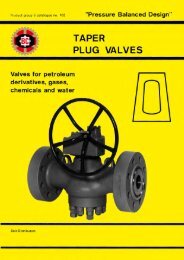
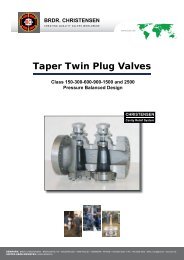
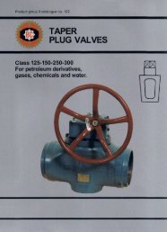
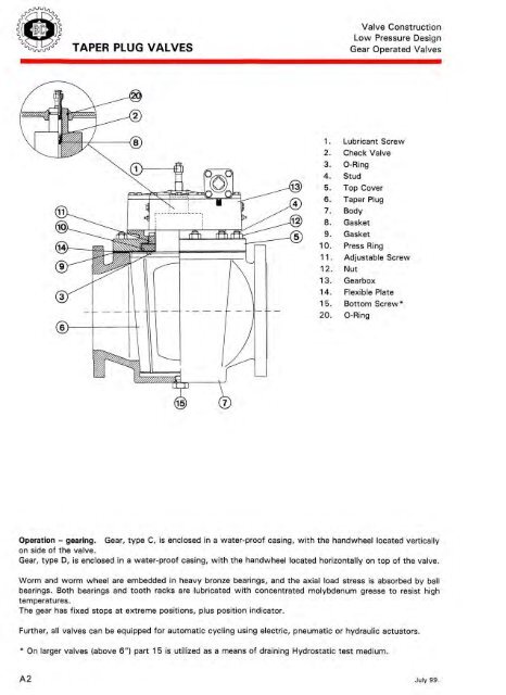
<strong>TAPER</strong> PLUG VALVES<br />
Valve Construction<br />
Low Pressure Design<br />
Gear Operated Valves<br />
1 .<br />
2.<br />
3.<br />
4.<br />
5.<br />
6.<br />
7.<br />
8.<br />
9.<br />
10.<br />
11 .<br />
12.<br />
13.<br />
14.<br />
15.<br />
20.<br />
Lubricant Screw<br />
Check Valve<br />
0-Ring<br />
Stud<br />
Top Cover<br />
Taper Plug<br />
Body<br />
Gasket<br />
Gasket<br />
Press Ring<br />
Adjustable Screw<br />
Nut<br />
Gearbox<br />
Flexible Plate<br />
Bottom Screw*<br />
0-Ring<br />
Operation -gearing. Gear, type C, is enclosed in a water-proof casing, with the handwheel located vertically<br />
on side of the valve.<br />
Gear, type D, is enclosed in a water-proof casing, with the handwheel located horizontally on top of the valve.<br />
Worm and worm wheel are embedded in heavy bronze bearings, and the axial load stress is absorbed by ball<br />
bearings. Both bearings and tooth racks are lubricated with concentrated molybdenum grease to resist high<br />
temperatures.<br />
The gear has fixed stops at extreme positions, plus position indicator.<br />
Further, all valves can be equipped for automatic cycling using electric, pneumatic or hydraulic actuators.<br />
* On larger valves (above 6") part 15 is utilized as a means of draining Hydrostatic test medium.<br />
A2 July 99.