oNeTrak Manual - NTRAK Modular Railroading Society, Inc.
oNeTrak Manual - NTRAK Modular Railroading Society, Inc.
oNeTrak Manual - NTRAK Modular Railroading Society, Inc.

Create successful ePaper yourself
Turn your PDF publications into a flip-book with our unique Google optimized e-Paper software.
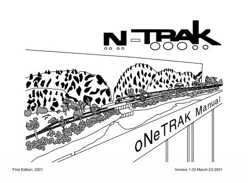
First Edition, 2001<br />
The oNeTRAK <strong>Manual</strong><br />
Version 1.00 March-23-2001
INDEX<br />
Page<br />
MAIN GOALS<br />
INTEGRATION<br />
ADDRESSES<br />
Specifications ........................... 3<br />
Basic module ............................ 4<br />
Offset and corner modules ....... 5<br />
DCC wiring tips .........................6<br />
Analog wiring tips .....................7<br />
Switch Wiring Tips .................... 8<br />
Main line junction ...................... 9<br />
Branch line junction ................ 10<br />
oNeTRAK junction .................. 11<br />
Operational tips ...................... 12<br />
Modules/Layout samples .. 13-15<br />
Connections/Distribution .........16<br />
DEFINITION<br />
oNeTRAK is an <strong>NTRAK</strong> compatible<br />
single-track branch line that can<br />
augment <strong>NTRAK</strong> layouts.<br />
1. Lightweight, simple to build<br />
modules, especially for beginners or<br />
those with limited transport capability.<br />
2. Provide an alternative to three<br />
track modules that can be connected<br />
to an <strong>NTRAK</strong> layout. Connected<br />
layouts encourage team building and<br />
enhance fun!<br />
3. Easy home layout integration<br />
4. Extend the <strong>NTRAK</strong> Red Line<br />
Route at shows<br />
5. Provide a branch line for more<br />
prototypical operations.<br />
6. Provide an easy way to model<br />
scenes with single track and tighter<br />
curves.<br />
7. Provides a section of the layout<br />
for serious switching operations<br />
when the rest of the layout is running<br />
lots of trains to hold the attention of<br />
spectators.<br />
oNeTRAK modules can be used to<br />
build stand alone layouts with<br />
emphasis on operation or can be<br />
connected with an <strong>NTRAK</strong> layout<br />
using junction modules either to<br />
lengthen the “Red Line Route” as<br />
seen on the sketch below or to have<br />
a branch line with sparse traffic. As<br />
the module design should permit both<br />
uses, all relevant standards for a<br />
conventional <strong>NTRAK</strong> module must<br />
be met by any oNeTRAK module.<br />
ELECTRICAL ISSUES<br />
<strong>NTRAK</strong> layouts in general and<br />
oNeTRAK modules in particular may<br />
be operated using conventional<br />
analog technology or digital DCC<br />
equipment. A module should conform<br />
to both requirements even if its builder<br />
or owner only intends to use it in one<br />
of the two modes.<br />
Bernard C. Kempinski<br />
1801 N. Beauregard Street<br />
Alexandria, VA 22311-1772<br />
USA<br />
bkempins@ida.org<br />
C. Matt Schaefer<br />
4301 Starr Jordan Drive<br />
Annandale, VA 22003<br />
USA<br />
ntrak@erols.com<br />
Simon Ginsburg<br />
Letzigraben 49<br />
CH-8003 Zürich<br />
Switzerland<br />
ntrak@freesurf.ch<br />
INTRODUCTION TO ONETRAK The oNeTRAK <strong>Manual</strong> 2
Most of these guidelines are based<br />
on <strong>NTRAK</strong> standards.<br />
1. HEIGHT OF TRACK Nominal<br />
height is 40 inches. To make grades<br />
longer than one module the module<br />
interface on grades may need to be<br />
changed from the 40 standard<br />
height.<br />
2. FRAME SIZES Frame lengths in<br />
multiples of one foot. Twelve inches<br />
is the minimum width. This width may<br />
be increased up to an additional foot,<br />
front or back for a total maximum<br />
width of three feet.<br />
3. MODULE INTERFACE Same as<br />
<strong>NTRAK</strong> with one clamp and the standard<br />
4.91" Atlas connector track section.<br />
The frame on the module end<br />
can be 1x3 or 1x4 lumber or plywood<br />
equivalent.<br />
4. TRACKS Code 80 track is standard.<br />
Code 55 is acceptable with<br />
code 80 transitions at module interface.<br />
Any Atlas, Peco or Micro Engineering<br />
code 80 or code 55 turnouts<br />
are acceptable. One track is required,<br />
additional through tracks are<br />
permitted.<br />
5. MINIMUM RADIUS is 18 inches<br />
with appropriate easements. To prevent<br />
binding the minimum length of<br />
tangent between all reverse curves<br />
must be 7 inches.<br />
6. LOCATION OF TRACK On<br />
straight modules the location of the<br />
main has no impact on the loop of<br />
modules and is not important, but<br />
generally the track is set back 4 to 6<br />
inches from the nominal front so that<br />
the Fascia may be reasonably<br />
aligned. Bump outs on the modules<br />
are permitted, same as <strong>NTRAK</strong>.<br />
Double or triple track should have<br />
1.5-inch center spacing at the module<br />
interface.<br />
7. CORNERS Standard corners<br />
can be 3 by 3 or 4 by 4 feet, etc. On<br />
a standard corner the track should be<br />
set back 6 inches from the nominal<br />
front edge. This makes layout design<br />
with inside corners easier. With track<br />
set in 6" modules can be used as inside<br />
or outside corners and maintain<br />
the one foot spacing increments.<br />
8. CLOSING LOOP LAYOUTS<br />
Due to the wide variety of frame sizes<br />
and locations of tracks, some gaps<br />
may develop in a loop layout. Most<br />
large loops should be flexible enough<br />
to close a gap by "scrunching" the<br />
modules together. In some cases a<br />
temporary bridge may be necessary.<br />
This can be made by using a piece of<br />
foam, some flex track and a bar<br />
clamp to close the gap.<br />
9. JUNCTIONS The smallest recommended<br />
junction is 3 by 5 feet.<br />
10. GRADES 1.5 percent maximum<br />
across a dedicated set of modules.<br />
Grades on other modules can<br />
be created with shims under legs of<br />
modules. Grades suggest addition of<br />
a helper district and helper engine<br />
facility.<br />
11. END TURNS are modules that<br />
include a 180-degree curve in the<br />
track. They should be a minimum of 2<br />
by 4 feet to allow the 18-inch minimum<br />
radius and easements. The distance<br />
between the ends of tracks on<br />
an end turn must be three feet or<br />
more in even foot increments.<br />
12. TURNOUT SIZES All turnouts<br />
should be number 6 or larger on the<br />
mains, passing sidings and interchange<br />
tracks. Number 6 turnouts<br />
are also encouraged in yards for better<br />
operation.<br />
13. ELECTRICAL The main line<br />
has a red plug fastened the same<br />
way as <strong>NTRAK</strong>. The white and 110<br />
volt requirements are the same as<br />
<strong>NTRAK</strong>. There are no special DCC<br />
related wiring requirements. <strong>NTRAK</strong><br />
standards for wire gauge suffice.<br />
14. SCENERY Any realistic scenery<br />
is permitted. Round down hills on<br />
the ends of modules so the view from<br />
an adjacent flat module looks like<br />
scenery. Colors for the fascia and<br />
skirts should blend with the scenery<br />
(generally shades of green or<br />
brown). Do not use diorama dividers.<br />
15. SKYLINE Skyboards or vertical<br />
scenery flats are optional. In many<br />
cases photography is easier if the<br />
skyboard is removable.<br />
16. PASSING SIDINGS To enhance<br />
operations most layouts<br />
should include several passing sidings.<br />
Clubs should try to include one<br />
or more standard passing sidings in a<br />
layout. A standard passing siding is a<br />
set of two 1 by 4 feet modules with<br />
turnouts at each end of the pair and<br />
double track connecting the turnouts.<br />
The resulting passing siding is about<br />
seven feet long. Double or triple track<br />
modules can be used to extend these<br />
sidings.<br />
17. OFFSET MODULES provide<br />
track offsets in one-foot increments<br />
for visual variety. Observe 18-inch<br />
minimum radius and tangent track<br />
between reverse curves standards.<br />
18. OPERATIONS SCHEME Although<br />
a stated purpose of<br />
oNeTRAK is to provide a venue for<br />
more prototypical operations, no operational<br />
scheme is specified. Clubs<br />
and individuals can tailor the operating<br />
scheme to their situation. To increase<br />
potential for realistic operation,<br />
wireless DCC is recommended.<br />
19. LAYOUT DESIGN oNeTRAK<br />
modules have proven very flexible in<br />
layout design both as part of an<br />
<strong>NTRAK</strong> layout or when standing<br />
alone. Note that <strong>NTRAK</strong> modules<br />
can be used in a 1T layout.<br />
SPECIFICATIONS The oNeTRAK <strong>Manual</strong> 3
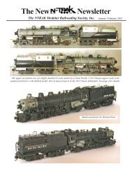
The basic module construction follows<br />
<strong>NTRAK</strong> specifications. Every module is to<br />
have four legs and be free standing to<br />
simplify setup and teardown. Modules can<br />
have a 1" layer of Styrofoam as deck sheet.<br />
Special care must be taken for the module<br />
to remain sufficiently stable. It's a good<br />
idea to have a sheet of luan plywood on the<br />
underside to prevent "punching through"<br />
while handling the module. Remember that<br />
when modules are clamped together that<br />
small gaps usually are filled by<br />
"scrunching" sets of modules together.<br />
12" min.<br />
36" max.<br />
4' Standard<br />
any multiple of 1' possible<br />
Lightweight Frame Construction<br />
1.5"<br />
4"-6"<br />
Make the cross member<br />
slightly smaller than frame<br />
so modules will not harm<br />
each other when stacked<br />
and cut holes for wiring.<br />
Conventional NTRK Frame Construction<br />
(as seen from below)<br />
4"<br />
Add second frame layer for<br />
additional strength<br />
1" Styrofoam<br />
Luan plywood<br />
Additional cross member<br />
3"-4"<br />
An additional cross<br />
member in the middle of<br />
the module adds a lot of<br />
strength and stiffness,<br />
without adding a lot of<br />
weight.<br />
4"<br />
Additional styrofoam layer<br />
for deeper contours<br />
Sufficient clearance for<br />
C-clamps required<br />
BASIC MODULE The oNeTRAK <strong>Manual</strong> 4
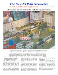
6"<br />
Offset modules add variety to the look of a layout.<br />
They will not cause operational rough spots if the<br />
minimum radius, easements, and a minimum distance<br />
between curves are considered and followed<br />
while doing the trackwork.<br />
Corner modules may be built as<br />
3'x3' or 4'x4'. Minimum radius must<br />
be kept and while bigger modules<br />
tend to be heavier and more difficult<br />
to transport, a curve with larger<br />
radius will always look better.<br />
36"<br />
Multiple of 1'<br />
6"<br />
4', 5' or 6'<br />
multiple of 1'<br />
When a oNeTRAK layout is designed to close a loop<br />
special care must be taken to stay with the one-foot grid<br />
while building modules. This is especially true with odd<br />
shaped or junction modules. When there's no intention to<br />
close a loop in the near future, there might be one later...<br />
Corners might be used as inside or outside corners.<br />
While the dimensional problem can be simplified by<br />
sticking to the 6" grid, the electrical connection for both<br />
uses can be prepared by providing two connectors on<br />
each side, male and female. The polarity of the second<br />
set must be switched in order to be right when the<br />
module is used with the "wrong" side.<br />
36"<br />
36"<br />
36"<br />
It is possible to cut out parts of the<br />
corner module in order to reduce its<br />
weight and space consumption.<br />
Special care then must be taken to<br />
leave enough strength and stiffness<br />
to prevent damage while clamping<br />
together the layout!<br />
A 4'x4' version of this design will<br />
need a stiffer frame, the reduction in<br />
size and weight is still remarkable<br />
compared with a conventional form<br />
(as seen above).<br />
The oNeTRAK <strong>Manual</strong><br />
OFFSET AND CORNER MODULES 5
Appoint a Digital “Master” This person is fully<br />
responsible for all aspects of the digital design for<br />
the Show, and for setup and for digital operations<br />
during the Show. The Digital Master and his crew<br />
must be thoroughly familiar with DCC equipment,<br />
its problems and solutions for the layout size being<br />
planned.<br />
Plan the Digital Layout Design as Carefully as<br />
the Layout Determine the number of Power<br />
Boosters, Radio/IR Receivers, Universal Panels<br />
and amount of LocoNet cable necessary to handle<br />
the configuration of the layout and the operations<br />
planned for the Show. Know who is supplying what<br />
equipment (if not Club-owned) and when it will be<br />
available during setup of the layout. Be sure to<br />
have a spare Command Station and Radio/IR<br />
Receiver.<br />
If you run lighted cars (e.g. Kato passenger cars)<br />
be sure to include their current draw in any Booster<br />
current calculations.<br />
Each booster will need its own isolated "block" and<br />
it's good practice to add a separate fast response<br />
circuit breaker so a short does not shut down the<br />
whole layout. The benefit is that you do not risk<br />
frying expensive rolling stock.<br />
Don't forget the coin test! It's a good idea to think<br />
ahead of what happens when a short occurs! The<br />
first test after the modules and all wiring is in place<br />
must be the "coin test". Short between rails close<br />
to the power source (booster) and then on the<br />
most distant piece of track. This checks that the<br />
wiring and connections in each section are<br />
adequate 1) to maintain sufficient voltage so that<br />
train control is not lost and 2) to allow the breaker<br />
to trip should there be a heavy short, preventing<br />
damage to N gauge equipment. If the coin test fails<br />
to trip the breaker, a separate jumper cable may<br />
be added parallel to the red wire along the modules.<br />
Rerun the coin test until successfully completed.<br />
Reversing Loops and Wyes Have Special<br />
Requirements On <strong>NTRAK</strong> layouts where there<br />
are no reversing loops or wyes, a single LocoNet<br />
will generally work fine, handling everything. When<br />
reversing loops and/or wyes are present separate<br />
LocoNets are mandatory. Further, there must be a<br />
ground wire (12 gauge preferred, 14 gauge<br />
minimum) between the ground terminals on all<br />
Power Boosters including the Command Station,<br />
and this ground wire should be connected to the<br />
power line ground at one point only. If the ground<br />
wiring is insufficient, unpredictable effects are<br />
likely to show up.<br />
Review Electrical Characteristics of All<br />
Modules in the Layout This is extremely important,<br />
especially for modules that have not been in a<br />
Show with digital operations. Even though the<br />
owner may state categorically that he followed the<br />
<strong>NTRAK</strong> rules for wiring modules, this may not be<br />
sufficient to ensure trouble free digital operation -<br />
what works fine with DC will sometimes not work<br />
well with DCC.<br />
Use Power Supplies Matched to the Power<br />
Boosters Do not use standard DC power packs of<br />
any type to supply Power Boosters. Always ensure<br />
the power supply is capable of producing at least<br />
the rated power output of the Power Booster it is<br />
supplying.<br />
Only One Command Station Can Command Be<br />
sure there is only one Command Station controlling<br />
the entire layout. Any other Command Station/<br />
Power Boosters used on the layout must be set to<br />
Booster-only mode. When the layout is REALLY<br />
big, the whole layout must be separated into two or<br />
more layouts linked with interchange blocks.<br />
It is good operating practice when a locomotive or<br />
locomotive consist is removed from the layout to<br />
also remove it from the DCC system - break down<br />
the consist to its individual locomotives and dispatch<br />
each locomotive from the system. This frees up<br />
slot memory for additional new locomotives.<br />
Stress Test the Layout Following Setup Always<br />
test everything before beginning normal operations.<br />
Run as many single locomotives as possible over<br />
the layout simultaneously. Some problems can<br />
only be found with high traffic density.<br />
Provide a Means of Programming Locomotives<br />
Always have some way to program locomotives.<br />
Someone may have just installed a decoder, or<br />
there may be a need to check the values of CVs in<br />
a decoder to diagnose a problem.<br />
Identify Ownership of All Digital Equipment To<br />
ensure the equipment is returned to its rightful<br />
owner after the Show is over, all digital components<br />
and equipment should be labeled with the owner’s<br />
name or some other well-known clearly identifiable<br />
marking. A return address label applied to the item<br />
is a simple and adequate means of identification.<br />
DCC WIRING TIPS The oNeTRAK <strong>Manual</strong> 6
Isolated rail joiners on both sides<br />
Siding<br />
Mainline<br />
Mainline<br />
OS-Section<br />
Main<br />
Red Line feeder wires<br />
The term “global” is introduced for<br />
a power supply not directly<br />
connected with a specific portion<br />
of track. Before operating with<br />
“global” power, one must use<br />
“Global” Left feeder wires (Colorcode: Black)<br />
“Global” Right feeder wires (Colorcode: Magenta)<br />
Standard wiring single track module(s)<br />
This plug can be used for<br />
“global” or local power supply.<br />
DPDT-Switches<br />
“Global” power supply<br />
through module wiring<br />
Gaps in feeder wires through open connectors<br />
switches to activate a connection. With conventional Two Cab<br />
“Global” power supply<br />
through separate wiring<br />
Control the cabs are named "A"<br />
and "B". Using horizontally<br />
mounted DPDT switches yields<br />
the names of two “global” power<br />
supplies to be “Left” and “Right”.<br />
Standard wiring The most simple<br />
way to control a oNeTRAK layout is<br />
to have all tracks fed by the same<br />
throttle. This might be a good idea<br />
for small layouts. With a growing<br />
number of modules there will be a<br />
demand to run more than one train<br />
simultaneously.<br />
Installing several independant<br />
blocks, each having its own throttle,<br />
will allow multiple train operation.<br />
But trains bypassing each other at<br />
sidings will cause major headaches<br />
for the operators and running trains<br />
by time table will not work well.<br />
Two Cab Control The sketch on<br />
this page shows how two power<br />
feeders running through a whole part<br />
of the layout can be used to allow<br />
usage of the same throttle while<br />
passing other trains. By using radio<br />
controlled throttles for left and right<br />
“global”, an engineer will be able to<br />
walk along his train and give himself<br />
control for specific parts of the layout<br />
by throwing the DPDT switches<br />
accordingly. The DPDT switches<br />
can, but do not have to be, integrated<br />
into the wiring of single track<br />
modules. It's recommended to<br />
provide for this wiring while building<br />
modules with sidings and yards.<br />
ANALOG WIRING TIPS The oNeTRAK <strong>Manual</strong> 7
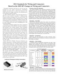
I<br />
II<br />
III<br />
IV<br />
V<br />
2<br />
1<br />
2<br />
1<br />
2<br />
1<br />
2<br />
1<br />
2<br />
1<br />
3<br />
3<br />
3<br />
3<br />
4 5<br />
9<br />
7<br />
9<br />
4 5 7<br />
1 and 2 are the feeder wires for this portion of track<br />
unless otherwise stated.<br />
All switches are solid or electrofrog type.<br />
Next<br />
Block<br />
8<br />
6<br />
8<br />
6<br />
Hand Thrown<br />
or<br />
Simple Wiring<br />
Switch Motor<br />
with<br />
Frog Feeder<br />
Switch Motor with<br />
Frog Feeder and<br />
Stop Block<br />
Switch Motor with<br />
Frog Feeder and<br />
Power Selection<br />
Switch Motor with<br />
Frog Feeder,<br />
Stop Block, and<br />
Power Selection<br />
1<br />
R N<br />
R N<br />
2<br />
1 2<br />
5<br />
4<br />
3<br />
R N<br />
9 7<br />
8<br />
6<br />
1<br />
2<br />
5 4<br />
3<br />
N is the straight position of the switch and the<br />
middle contacts are connected with the ones on<br />
the right. R is the reverse or turnout position of the<br />
switch and the left and middle contacts are<br />
connected.<br />
3<br />
9 7<br />
8<br />
6<br />
1<br />
2<br />
3<br />
R N<br />
WIRING TYPES<br />
For any discussion about junction, siding or yard<br />
wiring it might be useful to get some sort of<br />
common wiring schemes for individual switches.<br />
Any type is used with Electrofrog Turnouts with<br />
power routing through the switch tongue. Type I is<br />
the standard case with hand thrown turnouts;<br />
Type II - V are most likely used with switch motors.<br />
The switch contacts will require a fixed mechanical<br />
connection with the turnout tongue or unpredictable<br />
results will occur (spelled short circuit).<br />
WHAT TYPE TO USE<br />
This part is not to be understood as a MUST USE<br />
but rather as a help to decide which type best suits<br />
your demand. More complicated schemes will<br />
later help simplify the use of your module during<br />
operation.<br />
The stop block will help during more automatic<br />
operations to stop trains more safely (as with<br />
scheme I), as there cannot be a short when<br />
approaching a closed turnout. Schemes III and V<br />
are mainly for reverse loop or wye wiring. Special<br />
care must be taken that under no circumstances<br />
do two power supplies feed the same portion of<br />
track (or any portion of track or wiring in between),<br />
or the 'weaker' supply might fry!<br />
SWITCH WIRING TIPS The oNeTRAK <strong>Manual</strong> 8
BASIC IDEA<br />
OPERATIONS<br />
A oNeTRAK Mainline diverging from the Red Line<br />
of a standard modules division is basically done<br />
with a standard Junction module and a three to<br />
one track transition module.<br />
These Junction modules have been around for<br />
quite a while and have been mainly used to link two<br />
divisions' red line making up what Northern Virginia<br />
<strong>NTRAK</strong> called the "Red Line Route".<br />
When an extension of a loop is desired either two<br />
junction modules can be used (as seen on the<br />
right), or a combination of a junction module with<br />
a special module like Gordonsville is needed (as<br />
seen on the track plan on page 14).<br />
A single direction loop style scheme will not require<br />
any manipulations during operations. Trains follow<br />
each other and are guided either by tower<br />
operators, by block indicators or over radio by a<br />
dispatcher. Turnouts and electrical routing are<br />
preset and need not be remotely controlled.<br />
A more complex scheme permits individual routing<br />
of the trains and therefore the turnouts of the<br />
junction will be switched frequently. Remote control<br />
and automatic electric routing helps prevent<br />
mistakes and simplifies the work of the tower<br />
operator.<br />
P<br />
P<br />
Add standard modules<br />
to fit layout space<br />
P<br />
A<br />
Module can be as short as<br />
2' (610 mm)<br />
A<br />
A<br />
D<br />
P<br />
B<br />
C<br />
E<br />
P<br />
B<br />
C<br />
C<br />
B<br />
P<br />
A double line is a block boundary and a single line separates a<br />
stop block. P indicates a connection with a power supply.<br />
It is recommended to supply turnouts with the following wiring types:<br />
A, B: Type III if power supply at both ends, otherwise a V might be used<br />
C: Type III D,E: Type V<br />
MAIN LINE JUNCTION The oNeTRAK <strong>Manual</strong> 9
BASIC IDEA<br />
The main idea of the junction shown is to have the<br />
oNeTRAK subdivision directly connected with the<br />
blue line. Usually the blue line has most of the industries<br />
and sidings and can be put to good use with the<br />
oNeTRAK switching operations. A crossover over<br />
the main lines permits branch line operation with<br />
minimal interference of the main line activity on<br />
those modules.<br />
A scheme then can be set up to provide true car<br />
forwarding and time table and train order operations<br />
on the branch line while leaving the main lines to<br />
those that prefer a less strict regime of letting long<br />
trains loop for viewing pleasure.<br />
ELECTRICAL ISSUES<br />
The crossing between the main lines and the<br />
diverging branch lines requires an interlocking<br />
mechanism to prevent collisions. One solution is to<br />
allow switching off a portion of all tracks leading to<br />
the junction. This is easily done on the module itself<br />
and it would be a good idea to increase the security<br />
distance on the left side by having the first module<br />
to the left included in the stop block as well. A tower<br />
operator will then ensure the crash-free passage of<br />
the trains by aligning the turnouts, cutting off power<br />
at conflicting tracks, and communicating with the<br />
train engineers.<br />
A good place for the tower operator is at the back<br />
of the module overlooking all three approaching<br />
sides free of obstructions such as operators or<br />
visitors while being out of the way of passing<br />
operators. A tall chair with the required electrical<br />
switches and push buttons mounted on a panel<br />
within a comfortable reaching distance makes a<br />
perfect working environment. It is recommended to<br />
have the panel separate from the module for easier<br />
transportation and handling.<br />
While it is possible to have the turnouts thrown by<br />
hand it is recommended to install switch motors<br />
with the wiring type indicated. Adding turnout<br />
position feedback would even allow a remote CTClike<br />
control.<br />
A<br />
B<br />
C<br />
These two track plans use<br />
grade crossings over the main<br />
lines. While that has an impact on<br />
operation, it is far easier than<br />
building an overpass for the<br />
branch line.<br />
A<br />
B<br />
C<br />
It is recommended to supply turnouts<br />
with the following wiring types:<br />
A: Type V<br />
B: Type III<br />
C: Type II or III, if track behind backdrop<br />
will be used<br />
It is recommended to supply turnouts<br />
with the following wiring types:<br />
A: Type V<br />
B, C: Type III<br />
BRANCH LINE JUNCTION The oNeTRAK <strong>Manual</strong> 10
GENERAL DESIGN<br />
From the track planning point of view<br />
a junction module consists of two<br />
corner modules linked by a straight<br />
module. If the planning grid is kept,<br />
there is no problem closing several<br />
loops with junctions without<br />
scrunching any gap.<br />
The minimum size of a juncion is 3<br />
by 5 feet. The minimum radius can<br />
be met and there's even space for<br />
curve easements.<br />
As the wiring of a junction involves<br />
the reverse loop problem it is good<br />
practice to have all three approaching<br />
tracks on separate circuits. By<br />
throwing switches the current<br />
scheme of traffic then can be aligned.<br />
GORDONSVILLE JUNCTION<br />
Gordonsville Junction is the first<br />
oNeTRAK junction module and<br />
provides an example of how to adapt<br />
a prototype location to a modular<br />
layout system.<br />
The prototype Gordonsville has been<br />
an important rail junction since the<br />
1850s when the Orange and<br />
Alexandria made a connection there<br />
with the Virginia Central.<br />
The prototype track plan at<br />
Gordonsville is relatively simple. The<br />
conventional wye has tracks heading<br />
north to Alexandria, south to<br />
Richmond and west to<br />
Charlottesville. Today, only one<br />
additional track, a siding along the<br />
north-south leg, still stands. A brick<br />
tower, no longer used, stands at the<br />
west end, and the center of the wye<br />
contains the abandoned C&O water<br />
tower which is used for storage by<br />
the city of Gordonsville.<br />
Gordonsville's main street cuts<br />
diagonally through the wye. The west<br />
leg passes over the street on a low<br />
girder bridge, allowing a view of 19th<br />
century business structures from the<br />
rails.<br />
It took a few compromises to fit the<br />
track on a four-foot by 30-inch<br />
module. The west wye switch sits on<br />
the wrong side of the highway<br />
overpass, and the remaining siding<br />
to the outside of the wye. The track<br />
is isolated electrically into seven<br />
blocks which are connected together<br />
to suit the layout configuration. In<br />
most cases, no reverse loop wiring<br />
is needed.<br />
One of the features of the track plan<br />
is that the module can function in<br />
several different configurations:<br />
Junction (the usual mode); Corner;<br />
Straight; and Branch line connection.<br />
Because we forced the wye into a<br />
four-foot length, the curved legs have<br />
an effective radius of two and a half<br />
feet. oNeTRAK modules are<br />
designed in even foot increments.<br />
This means that six inches needs to<br />
be made up somewhere when the<br />
module is part of a loop. We have<br />
managed so far by making temporary<br />
six-inch bridges out of Styrofoam<br />
and by building a 2.5-foot module to<br />
compensate.<br />
To come out even, the module ought<br />
to be five feet by three feet, which is<br />
large for a oNeTRAK element. North<br />
Raleigh <strong>NTRAK</strong> has built some three<br />
track Junction modules in two<br />
sections, which could work for<br />
oNeTRAK as well. If the module<br />
were this size, in one or two sections,<br />
there would be room for a couple of<br />
industries. A run-around track would<br />
also help to make operations more<br />
interesting.<br />
ONETRAK JUNCTION The oNeTRAK <strong>Manual</strong> 11
1. Try to get longer sidings for operating flexibility.<br />
A switching scheme can be made up with a 6'<br />
maximum train length, but longer sidings with<br />
industries spread around make operations more<br />
interesting and planning them more flexible.<br />
2. Test out modules ahead of time. It's far too late<br />
to find a short circuit in your track work when the<br />
modules are to be clamped together at a Show! To<br />
be sure that all modules work flawlessly it's a good<br />
idea to have a test set up with all new or rebuilt<br />
modules. Don't forget to check all sidings and<br />
spurs.<br />
3. The planning of an operating scheme needs<br />
as much preparation as the planning of the layout<br />
itself. Special care should be taken to meet the<br />
expectations of the attending operators. An alldigital<br />
or all-analog layout is only a valid option if<br />
everybody agrees on doing so. The same applies<br />
to an all switching layout. The key idea for most<br />
cases is to have the layout split up into a digital and<br />
an analog district, and into portions with trains<br />
looping and others with local switchers at work.<br />
4. When car switching operation is desired, car<br />
cards or switching lists need to be made up in<br />
advance. A car pool must be collected and it must<br />
be certain that selected cars show up. For smaller<br />
schemes it is a good idea that the one preparing<br />
the switching operation uses his own cars<br />
exclusively.<br />
5. Prototypical operation needs a vast number<br />
of people! One single engineer per train is fine<br />
when the scheme is very simple and the engineer<br />
has some experience. When cars are to be<br />
switched a conductor is imperative. When the<br />
choosen switching scheme is new to the majority<br />
of the attendees, a three man crew will solve most<br />
problems. Staff planning is vital for a successful<br />
operating session. Five trains with a two man crew<br />
makes ten people. Add a dispatcher and a<br />
superintendent and you will need a dozen operators<br />
to fill the callboard for one session.<br />
6. Name everything! As with the prototype every<br />
location with relevance to operation needs a<br />
specific name, preferably being unique throughout<br />
the layout. If industries are to be served they need<br />
names too.<br />
7. Make sure that you have a system to identify<br />
the owner of all rolling stock. An easy solution is to<br />
color code the kingpin of the cars and the underside<br />
of the locomotives. Each member is assigned a<br />
unique color (or combination of two colors for<br />
larger clubs). The club keeps track of the colors<br />
already taken.<br />
8. Clean the Track and Clean the Wheels. This is<br />
good practice whether DC or DCC. The important<br />
message in this rule is to be sure that the track has<br />
dried from any liquid track cleaner (such as Goo<br />
Gone or 409) and that any residue has been<br />
removed. If trains are run while the track is still wet,<br />
then the train will spread any dirt that is coming off<br />
wheels or the residue of the cleaner all over the<br />
layout. Then you have a real problem. There are<br />
two ways to clean the track - use two Centerline<br />
cars with a wet cloth on the front roller and a dry<br />
cloth on the rear roller, or wipe the track with a wet<br />
rag or Q-tip then follow up with a dry rag. Clean<br />
wheel sets with a paper towel laid on a track and<br />
wetted with Goo Gone or 409. Roll the car back<br />
and forth and the gunk will come off. For<br />
locomotives, do one truck at a time on the towel<br />
with power applied so the wheels are turning.<br />
The oNeTRAK <strong>Manual</strong><br />
OPERATIONAL TIPS 12
A Gallery of oNeTRAK Modules and Ideas<br />
Moose Lake, Saskatchewan, CA<br />
Bernard Kempinski's 14 feet long by 18 <strong>Inc</strong>hes<br />
wide provides room for a long Passing Siding.<br />
Wingate, IN<br />
<strong>NTRAK</strong> version of a track plan<br />
published in MRP 1995.<br />
CP321, VA<br />
Dave Davies' oNeTRAK-to-<strong>NTRAK</strong> Adapter<br />
Module used as a lead to a <strong>NTRAK</strong> yard.<br />
Gordonsville, VA<br />
John Drye's Junction Module.<br />
Rickey Tick Junction<br />
Mike Langford's module based on a<br />
location on the Soo Line Northern Division<br />
Sunset Falls<br />
Lumber Mill<br />
Monica, WV<br />
Brian Brendel's End Turn Module Set<br />
Central Ridge Acts as a View Block.<br />
Also used as part of a home layout.<br />
Wilmore, KY<br />
Mark Franke's Small Town Module.<br />
Flour Mill<br />
Sarah's<br />
End Turn<br />
(Future Alaska Scene)<br />
Baxter's Farm, GA<br />
Bill Baxter's <strong>NTRAK</strong>-to-oNeTRAK Adapter<br />
Module features four crossovers<br />
Pete Matthews' oNeTRAK Layout<br />
Gravel Loader StagingYard W-O Junction<br />
Susan's<br />
End Turn<br />
(Future Town)<br />
MODULES/LAYOUT SAMPLES The oNeTRAK <strong>Manual</strong> 13
oNeTRAK part of the Orlando '98 Convention layout<br />
Offset module<br />
module with<br />
additional depth<br />
Standard <strong>NTRAK</strong><br />
layout<br />
corner<br />
modules<br />
Arrows show direction of traffic<br />
on extended Red Line Route<br />
180° return<br />
loop module<br />
Junction module<br />
This was the first appearance of oNeTRAK in large<br />
scale. The operating scheme extends the Red<br />
Line Route through this part of the layout. The<br />
Junction module (Gordonsville) permits both legs<br />
of the Route to pass through. Trains enter<br />
Gordonsville from the south on the right-hand<br />
track. They pass through a turnout and head north<br />
on single track. The engineer loops round<br />
oNeTRAK's main and reenters Gordonsville from<br />
the west. The train takes the right hand leg of the<br />
wye and continues off the module back to the<br />
"Gordonsville"<br />
south, this time on the second track. The straight<br />
leg of the wye (at the front of the module) is never<br />
used, so there is no reversing loop. An empty<br />
boxcar is usually parked on this leg, awaiting<br />
interchange and preventing operators from using<br />
the track. Trains that remain on the oNeTRAK loop<br />
during local operations can use the third leg of the<br />
wye.<br />
MODULES/LAYOUT SAMPLES The oNeTRAK <strong>Manual</strong> 14
oNeTRAK layout at Adliswil 2000 Convention<br />
This is the track plan of the Dease Lake &<br />
Northern, which proved to be a real show<br />
stopper during the 2000 Adliswil Convention.<br />
While all elements follow oNeTRAK<br />
specifications, they were designed to suit<br />
this configuration and the landscape flows<br />
smoothly from one module to the next. Such<br />
a layout is not expected to see fast trains<br />
looping. The main attraction is the barge<br />
operation over a lake made of real water.<br />
Operations follow time table and waybill<br />
instructions. Several industries are served<br />
and cars are swapped with another railroad<br />
symbolized by the tracks on the interchange<br />
at the left side of the layout.<br />
MODULES/LAYOUT SAMPLES The oNeTRAK <strong>Manual</strong> 15
CONNECTIONS TO OTHER SINGLE<br />
TRACKED STANDARDS<br />
FREMO<br />
ADDRESSES<br />
While oNeTRAK has proven to be a popular<br />
standard for single track modules, it is not the only<br />
standard. This page shows the differences and<br />
similarities among several standards to aid in<br />
tailoring various standards to a particular situation.<br />
Some standards, such as oNeCat, follow U.S.<br />
prototype. Others follow European prototype and<br />
are popular in Europe. There are even proposed<br />
standards for narrow gauge modules, but they<br />
have been omitted because of obvious problems<br />
connecting narrow gauge with standard gauge<br />
trackwork. There are several more standard<br />
descriptions published over the last few years but<br />
have not been included in the list as they either are<br />
no longer alive or are used by very few individuals<br />
only. If the authors of this manual did forget one of<br />
the rising stars, please give us a note!<br />
ONECAT<br />
The origin for these modules comes from NCat or<br />
those <strong>NTRAK</strong> modules that feature traction track<br />
along with the original three tracks. You will find a<br />
narrow minimum radius of 6" and steep grades of<br />
up to 4% as well as Catenary all along the tracks<br />
(hence the name...). Both the manual and sketches<br />
for interface-modules are to be published soon on<br />
the Internet.<br />
FREMO is a group which is mainly based in<br />
Germany with some activists in other European<br />
countries. There are standards for several scales<br />
and some of them (HO) are specalized for US<br />
prototype. A similar one for N scale has not yet<br />
been finalized. The main aim for FREMO is<br />
prototypical operation. There are no loop-style<br />
layouts. Modules therefore are relatively free in<br />
their form and only the end sides of a module are<br />
standardized.<br />
MAS 60<br />
Another mainly European standard with an<br />
emphasis on geometry. Lengths are in multiples of<br />
60 cm (~2') and the standard angle is 60°.<br />
Operations usually follow prototypical schemes<br />
but might be loop style on occasion. Module<br />
geometry is more strict than with FREMO but<br />
"multiple-segment-modules" are possible. The main<br />
theme follows European prototype, and standards<br />
are written for several scales.<br />
Currently, there are HO and N scale groups.<br />
oNeCat:<br />
Alex M. Postpischil: albabe@mindspring.com<br />
FREMO:<br />
www.fremo.org<br />
www.free-mo.org<br />
MAS 60:<br />
www.webdesign-tg.ch/mas60<br />
Eduard Isenring: isenringedi@hotmail.com<br />
MAS 60 N scale club:<br />
mypage.bluewin.ch/vsmsn/index.HTML<br />
Dieter Portmann: diespo@bluewin.ch<br />
DISTRIBUTION OF THE ONETRAK MANUAL<br />
The current On-Line version of this manual will<br />
be found at:<br />
www.ntrak.org<br />
www.ntrak.ch<br />
www.nvntrak.org<br />
A metric version of the oNeTRAK specifications<br />
for Australian conditions can be found at:<br />
homepages.picknowl.com.au/austnscale<br />
CONNECTIONS The oNeTRAK <strong>Manual</strong> 16