Consult-Exim Bt. 1025 Budapest Törökvész út 58. Tel: 394-1811 Fax ...
Consult-Exim Bt. 1025 Budapest Törökvész út 58. Tel: 394-1811 Fax ...
Consult-Exim Bt. 1025 Budapest Törökvész út 58. Tel: 394-1811 Fax ...

You also want an ePaper? Increase the reach of your titles
YUMPU automatically turns print PDFs into web optimized ePapers that Google loves.
<strong>Consult</strong>-<strong>Exim</strong> <strong>Bt</strong>.<br />
<strong>1025</strong> <strong>Budapest</strong> <strong>Törökvész</strong> <strong>út</strong> <strong>58.</strong><br />
<strong>Tel</strong>: <strong>394</strong>-<strong>1811</strong> <strong>Fax</strong>: 392-7118<br />
E-mail: info@consultexim.hu www.consultexim.hu<br />
1
<strong>Consult</strong>-<strong>Exim</strong> <strong>Bt</strong>.<br />
<strong>1025</strong> <strong>Budapest</strong> <strong>Törökvész</strong> <strong>út</strong> <strong>58.</strong><br />
<strong>Tel</strong>: <strong>394</strong>-<strong>1811</strong> <strong>Fax</strong>: 392-7118<br />
E-mail: info@consultexim.hu www.consultexim.hu<br />
2
<strong>Consult</strong>-<strong>Exim</strong> <strong>Bt</strong>.<br />
<strong>1025</strong> <strong>Budapest</strong> <strong>Törökvész</strong> <strong>út</strong> <strong>58.</strong><br />
<strong>Tel</strong>: <strong>394</strong>-<strong>1811</strong> <strong>Fax</strong>: 392-7118<br />
E-mail: info@consultexim.hu www.consultexim.hu<br />
• INTRODUCTION<br />
• MODULAR ELECTRONICS<br />
• LABORATORY STUDENT-TRAINER®<br />
• BASIC ELECTRONICS<br />
• LINEAR ELECTRONICS<br />
• DIGITAL ELECTRONICS<br />
• MICROPROCESSORS<br />
• INDUSTRIAL ELECTRONICS PROCESS CONTROL<br />
• INTERFACE WITH PERSONAL COMPUTER<br />
• MULTIMEDIA EDUCATIONAL SOFTWARE<br />
• COMPUTER-AIDED LEARNING SYSTEM<br />
• SERVOMECHANISMS<br />
• ELECTROMAGNETIC COMPATIBILITY<br />
• ELECTRONIC INSTRUMENTS AND ACCESSORIES S-1<br />
3
<strong>Consult</strong>-<strong>Exim</strong> <strong>Bt</strong>.<br />
<strong>1025</strong> <strong>Budapest</strong> <strong>Törökvész</strong> <strong>út</strong> <strong>58.</strong><br />
<strong>Tel</strong>: <strong>394</strong>-<strong>1811</strong> <strong>Fax</strong>: 392-7118<br />
E-mail: info@consultexim.hu www.consultexim.hu<br />
STUDENT - TRAINER® mod. MPT/EV...................................................................................................... 9<br />
EXPERIMENT MODULE mod. C20/EV.................................................................................................... 11<br />
DEVELOPMENT MODULE mod. C30/EV ............................................................................................... 12<br />
TRAINING PROGRAM.............................................................................................................................. 12<br />
OPERATIONAL AMPLIFIERS mod. C17/EV........................................................................................... 13<br />
TRAINING PROGRAM.............................................................................................................................. 13<br />
ANALOG SIGNAL PROCESSING mod. C19/EV .................................................................................... 14<br />
TRAINING PROGRAM.............................................................................................................................. 14<br />
MODULE FOR ANALYSIS AND.............................................................................................................. 16<br />
REALIZATION OF EXPERIMENTS......................................................................................................... 16<br />
OF DIGITAL ELECTRONICS mod. E18/EV............................................................................................. 16<br />
TTL, CMOS, HCT, ELC LOGIC FAMILIES AND INTERFACES mod. E05A/EV ................................. 17<br />
DEVICES FOR µP SYSTEMS mod. E16/EV ............................................................................................. 18<br />
SYSTEMS FOR THE STUDY OF .............................................................................................................. 19<br />
PROGRAMMABLE LOGIC mod. E17/EV ................................................................................................ 19<br />
8-BIT MICROPROCESSOR SYSTEM mod. Z1/EV................................................................................. 21<br />
16-BIT MICROPROCESSOR ..................................................................................................................... 22<br />
SYSTEM mod. Z2/EV ................................................................................................................................. 22<br />
32-BIT MICROPROCESSOR ..................................................................................................................... 23<br />
SYSTEM mod. Z3/EV ................................................................................................................................. 23<br />
Program for editing, compiling, linking and transmission from PC to module mod. Z3/EV: SW-Z3/EV... 23<br />
PROTOTYPES UNIT PROGRAMMING AND USE OF PARALLEL INTERFACE PROGRAMMING<br />
AND USE OF SERIAL INTERFACE mod. Z1A/EV ................................................................................. 24<br />
PROGRAMMING AND USE OF PARALLEL INTERFACE mod. F11A/EV.......................................... 26<br />
PERSONAL COMPUTER - MAINTENANCE AND TROUBLESHOOTING mod. PCTS/EV ............... 27<br />
POWER DEVICES AND REGULATION mod. C11/EV........................................................................... 29<br />
OPTOELECTRONIC DEVICES mod. C16/EV.......................................................................................... 30<br />
DC/AC AND DC/DC CONVERTERS WITH SCR-BJT-MOS mod. C18/EV ........................................... 31<br />
SINGLE-PHASE AND THREE-PHASE RECTIFIERS mod. C22/EV ...................................................... 32<br />
AC/DC SWITCHING POWER SUPPLY mod. C24/EV............................................................................. 33<br />
SINGLE-PHASE PWM INVERTER mod. C23A/EV................................................................................. 34<br />
ANALOG SWITCH AND SAMPLE & HOLD mod. G33/EV ................................................................... 35<br />
A/D AND D/A CONVERTERS mod. F03A/EV ......................................................................................... 36<br />
V/F AND F/V CONVERTERS mod. G21/EV............................................................................................. 37<br />
V/I AND I/V CONVERTERS mod. G32/EV .............................................................................................. 38<br />
POTENTIOMETRIC POSITION TRANSDUCER AND SIGNAL CONDITIONER mod. G22/EV ........ 40<br />
POSITION TRANSDUCER WITH LVDT AND SIGNAL CONDITIONER mod. G27/EV..................... 41<br />
POSITION TRANSDUCER WITH ENCODER AND SIGNAL CONDITIONER mod. F09/EV ............. 42<br />
PROXIMITY TRANSDUCER AND SIGNAL CONDITIONER mod. G29/EV........................................ 43<br />
PRESSURE TRANSDUCER AND SIGNAL CONDITIONER mod. G24/EV .......................................... 44<br />
FORCE TRANSDUCER AND SIGNAL CONDITIONER mod. G25/EV ................................................. 45<br />
SPEED AND ACCELERATION TRANSDUCER AND SIGNAL CONDITIONER mod. G28/EV......... 46<br />
POSITION TRANSDUCER WITH SYNCHRO RESOLVER AND SIGNAL CONDITIONER mod.<br />
G23/EV......................................................................................................................................................... 47<br />
FLOW AND LEVEL TRANSDUCER AND CONTROL mod. G30A/EV................................................. 48<br />
LUMINOSITY TRANSDUCER AND CONTROL mod. G13/EV ............................................................. 50<br />
TEMPERATURE TRANSDUCER AND CONTROL mod. G34/EV......................................................... 52<br />
PRESSURE TRANSDUCER AND CONTROL mod. G35/EV .................................................................. 54<br />
SPEED AND POSITION TRANSDUCER AND CONTROL mod. G36A/EV .......................................... 56<br />
SPEED CONTROL FOR THREE-PHASE MOTOR mod. G37/EV........................................................... 58<br />
PWM SPEED CONTROL FOR DC MOTOR mod. G14/EV...................................................................... 60<br />
STEPPER MOTOR CONTROL mod. G16/EV........................................................................................... 61<br />
PROCESS SIMULATOR mod. G26/EV ..................................................................................................... 62<br />
4
<strong>Consult</strong>-<strong>Exim</strong> <strong>Bt</strong>.<br />
<strong>1025</strong> <strong>Budapest</strong> <strong>Törökvész</strong> <strong>út</strong> <strong>58.</strong><br />
<strong>Tel</strong>: <strong>394</strong>-<strong>1811</strong> <strong>Fax</strong>: 392-7118<br />
E-mail: info@consultexim.hu www.consultexim.hu<br />
PID PROCESS CONTROL mod. PID-E/EV............................................................................................... 64<br />
PLC FOR PROCESS CONTROL mod. PLC-E/EV .................................................................................... 65<br />
INTERFACES WITH PERSONAL COMPUTER mod. MFI-I/EV ............................................................ 67<br />
BASIC ELECTRICITY cod. E-WIN ........................................................................................................... 71<br />
SIMULATED WORKBENCH cod. SWB-CC and cod. SWB-TR.............................................................. 71<br />
GENERAL ELECTRONICS cod. G-WIN................................................................................................... 72<br />
SIMULATED WORKBENCH cod. SWB-CE............................................................................................. 72<br />
DIGITAL ELECTRONICS cod. D-WIN..................................................................................................... 73<br />
SIMULATED WORKBENCH cod. SWB-DD and cod. SWB-DA............................................................. 73<br />
8-BIT AND 32 BIT MICROPROCESSOR cod. M-WIN and cod. P-WIN ................................................. 74<br />
SENSORS AND TRANSDUCERS cod. R-WIN......................................................................................... 75<br />
PROCESS CONTROL cod. S-WIN............................................................................................................. 75<br />
COMPUTER-AIDED LEARNING SYSTEM............................................................................................. 76<br />
SERVOMECHANISM FOR STEPPER MOTOR mod. SM1/EV............................................................... 78<br />
SERVOMECHANISM FOR DC-SHUNT MOTOR mod. DSD1/EV ......................................................... 79<br />
SERVOMECHANISM FOR PERMANENT MAGNETS DC MOTOR mod. MPD1/EV.......................... 80<br />
INVERTER FOR THREE-PHASE ASYNCHRONOUS MOTOR mod. TID1/EV.................................... 81<br />
SERVOMECHANISM FOR BRUSHLESS MOTOR mod. BMD1/EV...................................................... 82<br />
VECTORIAL FIELDORIENTED CONTROL SERVOMECHANISM FOR THREE-PHASE<br />
ASYNCHRONOUS MOTOR mod. FOC/EV.............................................................................................. 83<br />
MINI-ROBOT FOR STEPPER MOTORS mod. RB-4/EV ......................................................................... 84<br />
PACKAGE mod. PCRE/EV: “CONDUCTED AND RADIATED EMISSIONS”...................................... 87<br />
PACKAGE mod. PCS/EV: “IMMUNITY TO CONDUCTED DISTURBANCES”................................... 88<br />
INSTRUMENT UNIT mod. IU9/EV ........................................................................................................... 90<br />
POWER SUPPLY AND INSTRUMENT CONSOLE mod. 1444-A/EV .................................................... 90<br />
POWER SUPPLY CONSOLE mod. 1500-A/EV ........................................................................................ 91<br />
MEASUREMENT INSTRUMENTS........................................................................................................... 91<br />
VIRTUAL INSTRUMENTION - CAD-CAE SYSTEM mod. VTD/EV..................................................... 93<br />
LABORATORY POWER SUPPLIES......................................................................................................... 94<br />
COMPUTERIZED LCD PROJECTOR mod. LLC/EV ............................................................................... 94<br />
5
<strong>Consult</strong>-<strong>Exim</strong> <strong>Bt</strong>.<br />
<strong>1025</strong> <strong>Budapest</strong> <strong>Törökvész</strong> <strong>út</strong> <strong>58.</strong><br />
<strong>Tel</strong>: <strong>394</strong>-<strong>1811</strong> <strong>Fax</strong>: 392-7118<br />
E-mail: info@consultexim.hu www.consultexim.hu<br />
BASIC ELECTRICITY AND ELECTRONICS<br />
• Experiment module to carry out a wide range of experiments on basic electricity, electronic circuits, and<br />
devices, and linear microelectronics mod. C20/EV<br />
• Development module to carry out a wide range of linear and digital electronic circuits mod. C30/EV<br />
LINEAR ELECTRONICS<br />
• Operational amplifiers mod. C17/EV<br />
• Analog signal processing mod. C19/EV<br />
DIGITAL ELECTRONICS<br />
• Module for analysis and realization of experiments of digital electronics mod. E18/EV<br />
• TTL, CMOS, HCT, ELC logic families and interfaces mod. E05A/EV<br />
• Devices for microprocessor systems mod. E16/EV<br />
• Systems for the study of programmable logic mod. E17/EV<br />
MICROPROCESSOR<br />
• 8-bit microprocessor system mod. Z1/EV<br />
• 16-bit microprocessor system mod. Z2/EV<br />
• 32-bit microprocessor system mod. Z3/EV<br />
• Prototype unit mod. Z1A/EV<br />
• Programming and use of parallel interface mod. F11A/EV<br />
• Programming and use of seriale interface mod. F12/EV<br />
• Personal Computer maintenance and troubleshooting mod. PCTS/EV<br />
INDUSTRIAL ELECTRONICS<br />
• Power devices and regulators mod. C11/EV<br />
• Optoelectronic devices mod. C16/EV<br />
• DC-AC and DC-DC converters with SCR-BJT-MOS mod. C18/EV<br />
• Single-phase and three-phase rectifiers mod. C22/EV<br />
• AC/DC Switching power supply mod. C24/EV<br />
• Single phase PWM inverter mod. C23A/EV<br />
• Analog switch and sample & hold mod. G33/EV<br />
• A/D and D/A converters mod. F03A/EV<br />
• V/F and F/Vconverters mod. G21/EV<br />
• V/I and I/V converters mod. G32/EV<br />
INSTRUMENTATION AND PROCESS CONTROL<br />
• Potentiometric position transducer and signal conditioner mod. G22/EV<br />
• Position transducer with LVDT and signal conditioner mod. G27/EV<br />
• Position transducer with encoder and signal conditioner mod. F09/EV<br />
• Proximity transducer and signal conditioner mod. G29/EV<br />
• Pressure transducer and signal conditioner mod. G24/EV<br />
• Force transducer and signal conditioner mod. G25/EV<br />
• Speed and acceleration transducer and signal conditioner mod. G28/EV<br />
• Position transducer with synchro resolver and signal conditioner mod. G23/EV<br />
• Flow and level transducer and control mod. G30A-G30B/EV<br />
• Luminosity transducer and control mod. G13/EV<br />
• Temperature transducer and control mod. G34/EV<br />
• Pressure transducer and control mod. G35/EV<br />
• Speed & position transducer and control mod. G36A/EV<br />
• Speed control for 3-phase motor mod. G37/EV<br />
• PWm speed control for DC motor mod. G14/EV<br />
• Stepper motor control mod. G16/EV<br />
• Process simulator mod. G26/EV<br />
• PID process control mod. PID-E/EV<br />
• PLC for process control mod. PLC-E/EV<br />
PERSONAL COMPUTER INTERFACE<br />
• Plug-in interface card mod. MFI-I/EV Control and supervision software mod. MPTINT/EV<br />
• External interface mod. MFI-E/EV Control and supervision software mod. MPTEXT/EV<br />
• Interface in TCP/IP network mod. MFI-N/EV Control and supervision software mod. MPTNET/EV<br />
Development software mod. MPTDEV/EV<br />
6
<strong>Consult</strong>-<strong>Exim</strong> <strong>Bt</strong>.<br />
<strong>1025</strong> <strong>Budapest</strong> <strong>Törökvész</strong> <strong>út</strong> <strong>58.</strong><br />
<strong>Tel</strong>: <strong>394</strong>-<strong>1811</strong> <strong>Fax</strong>: 392-7118<br />
E-mail: info@consultexim.hu www.consultexim.hu<br />
MULTIMEDIA EDUCATIONAL SOFTWARE<br />
Software:<br />
• Basic electricity Cod. E-WIN<br />
• General electronics Cod. G-WIN<br />
• Digital electronics Cod. D-WIN<br />
• 8-bit microprocessor Cod. M-WIN<br />
• 32-bit microprocessor Cod. P-WIN<br />
• Sensors and transducers Cod. R-WIN<br />
• Process control Cod. S-WIN<br />
Simulators:<br />
• DC networks Cod. SWB-CC<br />
• Transitory state network Cod. SWB-TR<br />
• Analog electronic circuits Cod. SWB-CE<br />
• Basic digital circuits Cod. SWB-DD<br />
• Advanced digital circuits Cod. SWB-DA<br />
COMPUTER-AIDED LEARNING SYSTEM FOR THE STUDY OF ELECTRONICS<br />
SERVOMECHANISMS<br />
• Servomechanism for stepper motor mod. SM1/EV<br />
• Servomechanism for DC-shunt motor mod. DSD1/EV<br />
• Servomechanism for permanent magnets DC motor mod. MPD1/EV<br />
• Inverter for three-phase asynchronous motor mod. TID1/EV<br />
• Servomechanism for brushless motor mod. BMD1/EV<br />
• Vectorial field-oriented control servomechanism for three-phase asynchronous motor mod. FOC/EV<br />
• Mini-robot for stepper motors mod. RB-4/EV<br />
ELECTROMAGNETIC COMPATIBILITY<br />
• Package with instruments and accessories for: “Conducted and radiated emissions” mod. PCRE<br />
• Package with instruments and accessories for: “Conducted susceptibility” mod. PCS<br />
• Package with instruments and accessories for: “Radiated susceptibility” mod. PRS<br />
ELECTRONIC INSTRUMENTS AND ACCESSORIES<br />
• Instrument unit mod. IU9/EV<br />
• Power supply and instrument console mod. 1444-A/EV<br />
• Power supply console mod. 1500-A/EV<br />
• Measurement instruments<br />
• Virtual instrumentation – CAD-CAE system mod. VTD/EV<br />
• Laboratory power supplies<br />
• Computerized LCD projector mod. LLC/EV<br />
FURNITURE - Upon request<br />
7
<strong>Consult</strong>-<strong>Exim</strong> <strong>Bt</strong>.<br />
<strong>1025</strong> <strong>Budapest</strong> <strong>Törökvész</strong> <strong>út</strong> <strong>58.</strong><br />
<strong>Tel</strong>: <strong>394</strong>-<strong>1811</strong> <strong>Fax</strong>: 392-7118<br />
E-mail: info@consultexim.hu www.consultexim.hu<br />
PRESENTATION<br />
The great technological development of electronics in the last years caused a widespread use of equipment<br />
including electronic circuits. This requires highly qualified professional personnel with a proper training not only in<br />
the general aspects of electronics but also in the more advanced applications. The progress of technology and<br />
electronic components demands a continuous theoretical, experimental and practical updating of the operators of<br />
the field. In training, this creates the need of modular and flexible systems, which can match different and<br />
continuously changing requirements. ELETTRONICA VENETA & IN.EL. S.p.A. has developed an ideal<br />
educational environment for this purpose by designing a set of systems which enable the theoretical and<br />
experimental analysis of the subjects of electronics, from the basic concepts to the more complex themes.<br />
This catalogue, “ELECTRONICS, INSTRUMENTATION AND PROCESS CONTROLS”, shows the technology of<br />
today and the one which will be used in the next future. The modular and flexible training program, constantly<br />
enriched by innovative circuit solutions, enables a technologically updated training path. The suggested<br />
educational equipment and systems enable the layout of complete modular study programs, which can respond<br />
to the most specific needs of advanced training in the following main subjects:<br />
• Basic electronics • Linear electronics • Digital electronics • Microprocessors • Industrial electronics<br />
• Process control • Interfacing to the Computer • Servomechanisms • Electromagnetic compatibility<br />
The systems proposed are meaningful examples of the typical professional equipment of the field. They use the<br />
same technologies and the same devices employed in industrial systems: the only advantageous difference is<br />
their arrangement for interactive training. The presence in the laboratory of some of these equipment, which<br />
are of industrial kind and technologically advanced, ensures the essential connection between school and<br />
industrial reality. Allequipment have some characteristics which positively distinguish them in the world of<br />
technological training:<br />
• Flexibility: using the same equipment, it is possible to implement programs designed for different levels of<br />
instruction; besides, this characteristic enables the up-dating to the technological innovations, by introducing new<br />
modules.<br />
• High technological ad educational content: the Engineering staff of the Company converts the modern<br />
technology into clear and functional educational concepts.<br />
• Courseware: complete handbooks help the student in the theoretical study and experimental exercises.<br />
• Software: a Multimedia Educational Software is available for learning all subjects of electronics and<br />
telecommunications. (for the last part see cat. No. 21A –21B).<br />
By selecting the appropriate units from the wide range of equipment, users can set up tailor-made<br />
laboratories for the implementation of numerous study programs which are constructed to fulfill the<br />
specific needs of technological training, up to the highest levels. A gradual and progressive development of<br />
the laboratory can be articulated according to the subjects with the equipment listed hereafter:<br />
• Basic Electronics Laboratory<br />
For the layout, the STUDENT-TRAINER® (Sect.3) is used with the experiment modules chosen according to the<br />
required program. The modules can be supported by the “Multimedia Educational Software” (Sect. 11) for the<br />
theory and Simulations. The use of the Personal Computer enables to enlarge the Basic Laboratory with the<br />
following:<br />
– Interfacing to the Personal Computer (Sect.10) The connection is carried out with an industrial system,<br />
complete with data acquisition, control and supervision software for the experimental modules.<br />
– Educational network (Sect.12) For computerized learning, a data and video-keyboard exchange network<br />
enables a “Computer–aided learning system” methodology. The last enables the use of the most updated technical<br />
solutions, with great advantages from the pedagogical point of view:<br />
- Reduction of the study times and stronger stimuli to the students<br />
- Improved quality of the Teacher’s work<br />
- Continuous control of the learning level<br />
• Process control (Sect. 9) The experiments on the theory of automatic controls is carried out with the following<br />
equipment:<br />
- PID digital regulator complete with interface for the control of the processes suggested with the Student-Trainer<br />
- PLC complete with interface for control of the processes suggested with the Student-Trainer®<br />
- Process control “Fuzzy Logic” for regulation applications which can be more easily described with linguistic<br />
expressions than with mathematical models<br />
• Servomechanisms (Sect.13) A complete range of industrial servomechanisms mounted into the EDUBOX®‚<br />
structure, an innovative system for educational presentation combining the demonstration effectiveness to<br />
the operative functionality is dedicated to the study and experimentation of servomechanisms for electrical motors.<br />
• Electromagnetic compatibility (Sect. 14) Educational packages composed of professional instruments<br />
and educational modules set for experimental conformity tests, enable the lay-out of a laboratory for certification.<br />
Certification of conformity to the current rules on the emissions and susceptibility of electronic equipment,<br />
necessary to the CE mark.<br />
8
<strong>Consult</strong>-<strong>Exim</strong> <strong>Bt</strong>.<br />
<strong>1025</strong> <strong>Budapest</strong> <strong>Törökvész</strong> <strong>út</strong> <strong>58.</strong><br />
<strong>Tel</strong>: <strong>394</strong>-<strong>1811</strong> <strong>Fax</strong>: 392-7118<br />
E-mail: info@consultexim.hu www.consultexim.hu<br />
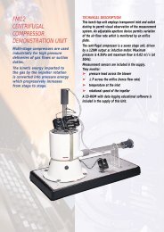
STUDENT - TRAINER® mod. MPT/EV<br />
The Student-Trainer® mod. MPT/EV is a modular<br />
system for theoretical/experimental learning in the<br />
whole range of Electronics and <strong>Tel</strong>ecommunications<br />
(for the last part, see catalogue no. 21A–21B).<br />
It consists of:<br />
• Power supply unit<br />
• Module-holder box<br />
• Experiment modules<br />
• Theoretical/Experimental handbooks.<br />
The handbooks provided with the experiment modules<br />
include the theoretical explanation of the exercises and<br />
the detailed instructions.<br />
The program of Electronics, Instrumentation and<br />
Process Control which can be developed with the<br />
Student-Trainer® mod. MPT/EV includes:<br />
• Basic electricity<br />
• Linear electronics<br />
• Digital electronics<br />
• Microprocessors<br />
• Industrial electronics<br />
• Process control<br />
The modules of the Student-Trainer® mod. MPT/EV can<br />
be interfaced to:<br />
– Personal Computer<br />
– Experiment modules of the Microprocessors<br />
– PID digital regulator<br />
– PLC<br />
Software packages with high graphical performances,<br />
enable to analyze the interfacing, control and<br />
supervision aspects in details. The modules of the<br />
Student-Trainer® mod. MPT/EV can be used for<br />
carrying out the exercises included in the “Multimedia<br />
Educational Software” for Electronics.<br />
9
<strong>Consult</strong>-<strong>Exim</strong> <strong>Bt</strong>.<br />
<strong>1025</strong> <strong>Budapest</strong> <strong>Törökvész</strong> <strong>út</strong> <strong>58.</strong><br />
<strong>Tel</strong>: <strong>394</strong>-<strong>1811</strong> <strong>Fax</strong>: 392-7118<br />
E-mail: info@consultexim.hu www.consultexim.hu<br />
The following units are used for the layout of the work-stations: POWER SUPPLY UNIT mod. PS1-PSU/EV<br />
The power supply unit consists in a container that creates an ergonomic unit with the module holder box. On the silk<br />
screen front plate, there are the terminals and the LEDs for taking and display the output voltages. These are available on<br />
DIN connectors set on the rear side of the power supply. The power supply unit is universal, as it is proper to power all<br />
kinds of modules produced by Elettronica Veneta & IN.EL. S.p.A. (Catalogues no. 21A, 21B, 33A, 34A, 35).<br />
The supplied voltages are:<br />
– Output S1: +30 Vdc – 4A. Rectified, filtered voltage protected with fuse. Voltage indicator LED.<br />
– Output S2: 24 Vac – 4A. Protection with fuse. Voltage indicator LED.<br />
– Output S3: +5 Vdc – 2A<br />
– Output S4: +12 Vdc – 2A, -12 Vdc – 0.5A. Stabilized voltages, electronically protected against short-circuits and<br />
overloads. Voltage indicator LEDs.<br />
– Output S5: 1.3 Vdc – 24 Vdc, 1A. Stabilized voltage, electronically protected against short-circuits and overloads.<br />
Voltage indicator LED.<br />
– Output on DIN connector: 24 Vac – 0 – 24 Vac, 0.5A. Voltage protected with fuse.<br />
(The outputs S1 and S2 provide 4A singularly and 2A if used simultaneously)<br />
– Power supply: 115/230 Vac, ±10%, 50/60 Hz<br />
– Max power: 150 VA<br />
– Dimensions and weight: 415x185x195 mm – 3 kg<br />
MODULE-HOLDER BOX mod. BOX/EV<br />
Support for housing the experiment modules. The modules can be fixed to the frame by using a “Plug-in” system.<br />
- Dimensions: 415x400x110 mm<br />
- Weight: 1Kg<br />
EXPERIMENT MODULES<br />
On the front panel, the modules show the electrical diagram, the block diagram and the test points of the circuit under test.<br />
The components are mounted on the rear section. A transparent cover protects them from accidental damage and leaves<br />
the circuit and the devices visible. Some modules include external units containing particular devices or circuits, such as<br />
transducers, actuators, power circuits, systems for generating physical quantities, etc. The modules are supplied with<br />
cables to be connected during the exercises.<br />
THEORETICAL-EXPERIMENTAL HANDBOOKS<br />
Each module or group of modules is provided with two handbooks. The first one includes:<br />
• A section describing the subject and the device or circuit under test<br />
• A set of experiments with detailed instructions, which simplifies understanding and learning of the theoretical aspects,<br />
and which enables the students to become familiar with measurements, regulations and calibrations relative to electronic<br />
circuits The second one includes information necessary to the installation and maintenance.<br />
10
<strong>Consult</strong>-<strong>Exim</strong> <strong>Bt</strong>.<br />
<strong>1025</strong> <strong>Budapest</strong> <strong>Törökvész</strong> <strong>út</strong> <strong>58.</strong><br />
<strong>Tel</strong>: <strong>394</strong>-<strong>1811</strong> <strong>Fax</strong>: 392-7118<br />
E-mail: info@consultexim.hu www.consultexim.hu<br />
EXPERIMENT MODULE mod. C20/EV<br />
The experiment module mod. C20/EV is the proper support<br />
for developing the exercises included in the Laboratory of<br />
General Electronics. It allows a wide range of experiments<br />
which subjectmatters are divided into three parts:<br />
• Basic electricity<br />
• Electronic circuits and devices<br />
• Linear microelectronics<br />
The exercises relative to the program of Basic Electricity<br />
enable students to acquire general knowledge of electricity<br />
and a.c./d.c circuits, and on the use of the electrical<br />
instrumentation. While those related to the program for<br />
Electronic Circuits and Devices include the detection of the<br />
semiconductor components characteristics and their<br />
use in the basic electronic circuits. The development of the<br />
Linear Microelectronics program enables the student to<br />
learn the operations and applications typical of linear<br />
integrated circuits. This subject includes Operational<br />
Amplifiers and their different connections, the voltage<br />
regulators, the timers and the integrated audio amplifiers.<br />
EXPERIMENT MODULE mod. C20/EV<br />
The system consists in a base circuit with proper step and<br />
a wide range of components welded on terminal boards<br />
with standard pins for a proper insertion into the basic<br />
circuit. In this way, it is possible to assemble any kind of<br />
circuit by inserting the wished components. The power<br />
supplies and connections between components are<br />
carried out via cables.<br />
TRAINING PROGRAM<br />
The module mod. C20/EV enables the theoretical analysis<br />
and the experiments on the following main subjects:<br />
Basic electricity:<br />
• Electricity, measurement units and symbols<br />
• DC electrical supplies, switches and relays<br />
• Use of power supplies and measurement instruments<br />
• Ohm’s law • Series and parallel resistive circuits, voltage<br />
dividers, attenuators • Kirchoff’s laws<br />
• Superimposition theorem • Thevenin’s and Norton’s<br />
theorem • DC power • Power transfer<br />
• Capacitance and capacitors • Inductance and inductors<br />
POWER SUPPLY: ±12 Vdc / 0.5A, +5 Vdc / 2A, 24 Vac<br />
SUGGESTED POWER SUPPLY AND ACCESSORIES<br />
• Power supply unit mod. PS1-PSU/EV<br />
• Module-holder box mod. BOX/EV<br />
REQUIRED INSTRUMENTS<br />
• Multimeter • Function generator • Oscilloscope<br />
THEORETICAL-EXPERIMENTAL HANDBOOKS<br />
• Theoretical-application handbook of the module with easy<br />
guide to the exercises<br />
• Installation, use and maintenance handbook<br />
• Alternating signals: waveform, mean value, root mean<br />
square (rms) value, period and frequency<br />
• Use of function generator and oscilloscope<br />
• AC resistive, inductive, capacitive circuits<br />
• Active and reactive power<br />
• Transformers<br />
• Series and parallel resonance<br />
Electronics circuits and devices:<br />
• Introduction to semiconductors<br />
• PN junction, diode<br />
• Half-wave, full-wave, Graetz bridge rectifiers<br />
• Smoothing and filtering circuits<br />
• Clipping circuits, voltage doublers, clamping circuits<br />
• Zener and Varicap diodes<br />
• Optoelectronic components<br />
• NTC and PTC thermistors<br />
• NPN and PNP transistors<br />
• J-FET, MOS-FET, UJT, PUT, DIAC, SCR, TRIAC<br />
• Transistor connections: common emitter, common<br />
collector, common base<br />
• Bias stabilization<br />
• Small signal parameters<br />
• Dual load amplifier<br />
• Multistage amplifier: RC, transformer, direct coupling<br />
• Differential amplifier<br />
• Darlington, Cascode, Bootstrap circuit<br />
• Class A and class B amplifiers<br />
• Push-pull, complementary symmetry, single-ended<br />
configuration<br />
• Oscillators: RC, Wien bridge, Colpitts, Hartley, Meissner,<br />
quartz<br />
• Monostable, bistable, astable, Schmitt trigger<br />
multivibrators<br />
Linear microelectronics<br />
• Integrated operational amplifier: typical parameters<br />
• Applications of the operational amplifier: inverting and<br />
non-inverting, summing, subtractor, integrator,<br />
differentiator, comparator, logarithmic<br />
• Monostable and astable multivibrator<br />
• Voltage-frequency converter<br />
• Sine, rectangular, triangular, ramp wave-form generator<br />
• Low pass, high pass, band pass active filter<br />
• Monolithic voltage regulators; output stabilization at<br />
variations of the load and the power supply<br />
• Integrated timer: characteristics and applications<br />
• Audio power amplifier: typical parameters<br />
TECHNICAL SPECIFICATIONS<br />
• Various types of connector jacks for quick assembly of<br />
the circuits<br />
• Panel with silk-screen printing of the connections between<br />
terminals<br />
• Components mounted on support with metal terminals<br />
and silkscreen printing of the component<br />
DIM.: 386x372x40mm<br />
Accessories:<br />
• Set of 140 components (resistors, capacitors,<br />
inductances, potentiometers, transformers, diodes,<br />
transistors, integrated circuits, etc.) necessary to the<br />
development of all exercises suggested in the handbook<br />
• Case for the components<br />
• Set of connector cables<br />
11
<strong>Consult</strong>-<strong>Exim</strong> <strong>Bt</strong>.<br />
<strong>1025</strong> <strong>Budapest</strong> <strong>Törökvész</strong> <strong>út</strong> <strong>58.</strong><br />
<strong>Tel</strong>: <strong>394</strong>-<strong>1811</strong> <strong>Fax</strong>: 392-7118<br />
E-mail: info@consultexim.hu www.consultexim.hu<br />
DEVELOPMENT MODULE mod. C30/EV<br />
The development module mod. C30/EV permits to carry<br />
out and check a wide range of linear and digital electronic<br />
circuits; it also enables the ready handiness for cabling and<br />
testing the circuits.<br />
DEVELOPMENT MODULE mod. C30/EV<br />
The module is developed into many parts, each of which<br />
carries out a specific function. Particularly, the following<br />
blocks are present:<br />
• VOLTAGE: enabling the connection of the module to the<br />
necessary voltages coming from an external power supply<br />
(STANDARD version) or generated internally (STAND<br />
ALONE version).<br />
• FUNCTION GENERATOR: it is a function generator with<br />
variable frequency and sine, triangle, square, pulse<br />
waveform; all these signals can be obtained<br />
simultaneously. The amplitude and the d.c.<br />
component of the signal can be adjusted separately for<br />
each output waveform.<br />
• TTL GENERATOR: it is a generator with output voltage at<br />
TTL level and frequency ranging between 1 Hz and 1 MHz.<br />
• LOGIC INPUTS: they consist in a set of 8 lever switches<br />
and 2 pushbuttons.<br />
• HEXADECIMAL KEYBOARD: the unit consists in a 16-<br />
key keyboard and 4 terminals from which the signals<br />
corresponding to the key pressed can be taken, and 4 leds<br />
which hexadecimal decoding identifies which key has been<br />
pressed.<br />
• ANALOG INPUTS: consisting in 4 potentiometers of<br />
different value with three terminals available: thus they can<br />
be used with circuits via the breadboards.<br />
• DISPLAY: it consists in a 4-digit display. The coding for<br />
each digit of the display is in BCD logic and each digit has<br />
four terminals available to introduce the value to be<br />
displayed.<br />
• LOGIC INDICATORS: they consist of leds accessed via<br />
terminals. The logical levels are TTL and if the logical level<br />
is high, the corresponding led turns on.<br />
• BREADBOARD: 4 breadboards are inserted into the<br />
module which permit to insert the electronic components to<br />
carry out the different circuits. The BREADBOARDs can be<br />
extracted from the module to preserve the carried out<br />
circuit.<br />
POWER SUPPLY: ±12 Vdc / 0.5A, +5 Vdc / 2A, 24 Vac<br />
SUGGESTED POWER SUPPLY AND ACCESSORIES<br />
(ref. pag. 3-4)<br />
• Power supply unit mod. PS1-PSU/EV<br />
• Module-holder box mod. BOX/EV<br />
TRAINING PROGRAM<br />
The module mod. C30/EV enables the theoretical analysis<br />
and the experiments on the following main subjects:<br />
• Half- and full-wave rectifiers<br />
• Regulated power supplies with discrete components and<br />
integrated circuits<br />
• Amplifiers: differential, wide-band, selective, in class C,<br />
with complementary symmetry<br />
• Meissner, Hartley and Colpitts oscillators<br />
• Astable, monostable and bistable multivibrators and<br />
Schmitt trigger<br />
• Voltage regulators with UJT, SCR, DIAC and TRIAC<br />
• Circuits with operational amplifiers<br />
• Multivibrators, oscillators, active filters by means of<br />
operationals<br />
• Waveform generators • OR-AND-NOR-NAND-NOT ports<br />
with discrete components, integrated circuits and<br />
combinatory logic networks • Sequential logic networks<br />
with flip-flop RS, D, JK, JK Master-Slave and Latch<br />
• 4-bit shift registers • Binary and decade counters<br />
• Decoder and driver for 7-segment display or multiplexer<br />
and demultiplexer<br />
TECHNICAL SPECIFICATIONS<br />
• Mounting plate which can be inserted or extracted via<br />
breadboards with 2200 connection points<br />
• Function generator with:<br />
- waveform: sine, square, triangle, pulse with independent<br />
outputs which can also be used contemporarily<br />
- frequency: 0.1 Hz-100 KHz<br />
- amplitude: ranging between 0 and 16 Vpp (for the pulse<br />
output variable between 0 and 8 V)<br />
- offset: variable between ± 8 V<br />
- amplitude and offset with separate control<br />
- pulse duration: adjustable independently from frequency<br />
• TTL generator: 1 Hz – 1 MHz<br />
• Hexadecimal keyboard<br />
• 4-Digit display with BCD coding<br />
• 8 Switches and 2 pushbuttons with antibounce circuit<br />
• 8 Led diodes with driver<br />
• 1 Loudspeaker: 8 Ohm, 0.5 W<br />
• 4 Potentiometers: 2 KOhm, 5 KOhm, 10 KOhm and 100<br />
Kohm<br />
Accessories:<br />
• Set of 240 components including: resistors, capacitors,<br />
trimmers, diodes, transistors, SCR, Triac, integrated<br />
circuits, leds, display…<br />
DIM. : 386x372x40 mm<br />
THE MODULE IS AVAILABLE IN TWO VERSIONS:<br />
• In STANDARD version with power supply provided by<br />
external power unit (mod. PS1-PSU/EV).<br />
• In STAND ALONE version. In this case the module is<br />
fixed to the module holder box containing the power supply<br />
with the following output voltages:<br />
- +5 Vdc / 2A, ±12 Vdc / 1A, +30 Vdc / 4A, 24 Vac / 4A<br />
- 1 3-digit digital voltmeter with bias indication and<br />
possibility to<br />
measure d.c. and a.c. voltages<br />
- mains power voltage, 220 V / 50Hz<br />
REQUIRED INSTRUMENTS<br />
• Multimeter • Oscilloscope<br />
THEORETICAL-EXPERIMENTAL HANDBOOKS<br />
12
<strong>Consult</strong>-<strong>Exim</strong> <strong>Bt</strong>.<br />
<strong>1025</strong> <strong>Budapest</strong> <strong>Törökvész</strong> <strong>út</strong> <strong>58.</strong><br />
<strong>Tel</strong>: <strong>394</strong>-<strong>1811</strong> <strong>Fax</strong>: 392-7118<br />
E-mail: info@consultexim.hu www.consultexim.hu<br />
OPERATIONAL AMPLIFIERS mod. C17/EV<br />
The subjects included in the field of Linear Electronics<br />
concern the analytical and, consequently, application<br />
principles of circuits concerned in the generation and<br />
processing of signals strictly continuous in time.<br />
Operational amplifiers find here their most<br />
important application, in a wide series of circuit<br />
configurations. The module C17/EV enables, first, the<br />
study of the characteristic parameters of the operational<br />
amplifiers and, then, the study of the circuit<br />
configurations that can be set up with them.<br />
OPERATIONAL AMPLIFIERS mod. C17/EV<br />
The operational amplifiers, which have a cascade of<br />
stages inside, are characterized by some parameters<br />
that provide the indexes of the performances. In this<br />
case, mod. C17/EV enables the measurement of the<br />
main parameters of the operational amplifier such as:<br />
CMRR, slew-rate, pass band, bias current,<br />
offset, input resistance, etc. The measurements with<br />
the oscilloscope can be carried out in many points (test<br />
points) directly accessible to the student, reported on<br />
the silk screen front panel made in insulating material.<br />
In this way, it is possible to directly compare with the<br />
characteristics of the integrated circuit, reported on the<br />
handbook provided by the manufacturer. In a next<br />
phase, mod. C17/EV includes the possibility of the<br />
layout of some circuit configurations, among which the<br />
most used ones are: signal amplifiers, wave-form<br />
generators, active filters, comparators, etc. Such<br />
experiments are facilitated by inserting jumpers for the<br />
connection of passive and active components to the<br />
operational amplifier. The presence of two<br />
operational amplifiers in the module enables the<br />
construction of more complex circuit types.<br />
In this case, too, it is possible to use the oscilloscope to<br />
measure the waveforms present in the circuit and their<br />
values. The educational path is completed by the<br />
comparison, made by the student, of these results with<br />
those calculated with the formulae during the theoretical<br />
study.<br />
THEORETICAL-EXPERIMENTAL HANDBOOKS<br />
• Theoretical-application handbook of the module with<br />
guide to the applications of Linear Electronics<br />
• Installation, use and maintenance handbook<br />
TRAINING PROGRAM<br />
The module mod. C17/EV enables the theoretical<br />
analysis and the experiments on the following main<br />
subjects:<br />
• Operational amplifiers: characteristic parameters<br />
• Offset voltage measurements<br />
• Slew-rate measurement<br />
• Band width measurement<br />
• Open loop gain measurement<br />
• Application of the integrated operational amplifier:<br />
inverting amplifier<br />
• Non-inverting amplifier<br />
• Summing amplifier<br />
• Subtractor amplifier<br />
• Integrator amplifier<br />
• Differentiator amplifier<br />
• Comparator amplifier<br />
• Logarithmic amplifier<br />
• Monostable multivibrator<br />
• Astable multivibrator<br />
• Schmitt trigger<br />
• Sine oscillator<br />
• Waveform generator: square, triangular, saw-tooth<br />
• Voltage/frequency converter<br />
• Low pass filter<br />
• Band pass filter<br />
• High pass filter<br />
• Determination of the transfer characteristic of the<br />
configured filters<br />
TECHNICAL SPECIFICATIONS<br />
• Front panel in insulating material, with silk screen<br />
diagram of the different circuit blocks of the module and<br />
electrical diagram of each circuit<br />
• Terminals for the connections and measurements<br />
• Two operational amplifiers to evaluate the<br />
performances<br />
• Passive components: resistors and capacitors of<br />
different nominal value, which can be connected to the<br />
operational amplifiers<br />
• Active components: diodes and transistors that can be<br />
connected to the operational amplifiers<br />
• 1 rotary potentiometer for the input voltage variation<br />
across the circuits from 0 to 12 V<br />
• 1 potentiometer for changing the circuits parameters<br />
• Final stage with BJT transistor for voltage/frequency<br />
converter<br />
• Assembling of different circuits by jumpers<br />
introduction<br />
DIM: 386x248x50 mm<br />
POWER SUPPLY<br />
±12 Vdc / 0.5 A<br />
SUGGESTED POWER SUPPLY AND ACCESSORIES<br />
(ref. pag. 3-4)<br />
• Power supply unit mod. PS1-PSU/EV<br />
• Module-holder box mod. BOX/EV<br />
REQUIRED INSTRUMENTS<br />
• Multimeter • Function Generator • Oscilloscope<br />
13
<strong>Consult</strong>-<strong>Exim</strong> <strong>Bt</strong>.<br />
<strong>1025</strong> <strong>Budapest</strong> <strong>Törökvész</strong> <strong>út</strong> <strong>58.</strong><br />
<strong>Tel</strong>: <strong>394</strong>-<strong>1811</strong> <strong>Fax</strong>: 392-7118<br />
E-mail: info@consultexim.hu www.consultexim.hu<br />
ANALOG SIGNAL PROCESSING mod.<br />
C19/EV<br />
In Linear electronics, the analog processing of signals<br />
represents the next step to the study of operational<br />
amplifiers. It constitutes a subject that nowadays<br />
crosses fields apart between them such as industrial<br />
electronics and telecommunications. In this context, the<br />
module mod. C19/EV is a complete, autonomous unit<br />
for the development of applications concerning the<br />
different processing and treatments which can be<br />
carried out<br />
on analog signals, using modern industrial components<br />
in order to obtain top level performances.<br />
ANALOG SIGNAL PROCESSING mod. C19/EV<br />
Module mod. C19/EV implements different kinds of<br />
signal<br />
processing, from simple algebraic operations of addition<br />
and subtraction to more complex ones of modulations<br />
and demodulations. In this sense, it represents a real<br />
analog processor with components really used in the<br />
professional practice and that are commonly found in<br />
the market. Module mod. C19/EV enables, in this way,<br />
the detailed study of the theoretical subjects concerning<br />
signal processing, with an easy development of the<br />
experimental phase. Each specific function, that can be<br />
carried out on the signal, is symbolized by a functional<br />
block which is silk screen printed on the front panel of<br />
the module. Here, you can access the inputs and the<br />
outputs to carry out the measurements with<br />
oscilloscopes or multimeters. On the module, there are<br />
variable components for the manual control and<br />
calibration of the circuits. More complex functions can<br />
be carried out, instead, by connecting different blocks<br />
together via jumpers. On the module mod. C19/EV,<br />
there are three fixed frequency signals and a variable<br />
frequency signal generator (square, triangle and sine<br />
wave). This eases the carrying out of experiences by<br />
the student by limiting the use of external generators.<br />
TRAINING PROGRAM<br />
The module mod. C19/EV enables the theoretical<br />
analysis and the experiments on the following main<br />
subjects:<br />
• Sum and difference of analog signals<br />
• Attenuation of an analog signal<br />
• Exponential functions • Logarithmic functions<br />
• Multipication • Division<br />
• Raising to a power • Square root<br />
• Integration • Shunt<br />
• Peak detector • Automatic gain control (AGC)<br />
• AM modulation and demodulation<br />
• Switching capacity filters (SCF)<br />
• VCO and PLL<br />
TECHNICAL SPECIFICATIONS<br />
• Front panel in insulating material, with silk screen<br />
printed diagram of the different blocks of the module<br />
and electrical diagram of each circuit<br />
• Terminals for the connections and measurements<br />
• Attenuator with attenuation ranging between 0 and 15<br />
dB with steps of 1 dB<br />
• Load resistance of the attenuator R=600 Ohm<br />
• 1 Signal generator, with variable frequency, on the<br />
module:<br />
- sine, triangle, square output<br />
- frequency variable via potentiometer accessible<br />
externally; control voltage variable from 0 to 8 V<br />
• 1 Fixed frequency signal generator with:<br />
- 2 square-wave outputs f1=100 kHz, f2=1 kHz<br />
- 1 sine output f=500 Hz<br />
• PLL with frequency gain variable from 1 to 99<br />
insertable by 2-digit contraves<br />
• Gain of the integrator and shunt blocks, variable with 2<br />
rotary potentiometers<br />
• Logarithmic block input: 0.1 – 10 V; output -1 – 1 V<br />
• Anti-logarithmic block input: -1 – 1V; output 0.1 –10V<br />
• 2 Multiplier blocks<br />
• 2 Rotary potentiometers for general use which can be<br />
connected to the blocks via jumpers<br />
DIM: 386x248x50 mm<br />
POWER SUPPLY<br />
±12 Vdc / 0.5 A<br />
SUGGESTED POWER SUPPLY AND ACCESSORIES<br />
(Ref. pag. 3-4)<br />
• Power supply unit mod. PS1-PSU/EV<br />
• Module-holder box mod. BOX/EV<br />
REQUIRED INSTRUMENTS<br />
• Oscilloscope • Multimeter<br />
THEORETICAL-EXPERIMENTAL HANDBOOKS<br />
• Theoretical-application handbook of the module with<br />
guide to the applications of Linear Electronics<br />
• Installation, use and maintenance handbook<br />
14
<strong>Consult</strong>-<strong>Exim</strong> <strong>Bt</strong>.<br />
<strong>1025</strong> <strong>Budapest</strong> <strong>Törökvész</strong> <strong>út</strong> <strong>58.</strong><br />
<strong>Tel</strong>: <strong>394</strong>-<strong>1811</strong> <strong>Fax</strong>: 392-7118<br />
E-mail: info@consultexim.hu www.consultexim.hu<br />
DIGITAL ELECTRONICS 6-1<br />
Module for analysis and realization of experiments of digital electronics mod. E18/EV 6-3<br />
TTL, CMOS, HCT, ELC logic families and interfaces mod. E05A/EV 6-5<br />
Devices for µP systems mod. E16/EV 6-7<br />
Systems for the study of programmable logic mod. E17/EV 6-<br />
15
<strong>Consult</strong>-<strong>Exim</strong> <strong>Bt</strong>.<br />
<strong>1025</strong> <strong>Budapest</strong> <strong>Törökvész</strong> <strong>út</strong> <strong>58.</strong><br />
<strong>Tel</strong>: <strong>394</strong>-<strong>1811</strong> <strong>Fax</strong>: 392-7118<br />
E-mail: info@consultexim.hu www.consultexim.hu<br />
MODULE FOR ANALYSIS AND<br />
REALIZATION OF EXPERIMENTS<br />
The module enables the analysis and realization of a<br />
wide range of digital electronic circuits. The necessary<br />
components are already present in the module and are<br />
mounted so that the experiments are very easy,<br />
especially as concerns the more complex logical<br />
circuits.<br />
MODULE FOR THE ANALYSIS AND REALIZATION<br />
OF EXPERIMENTS OF DIGITAL ELECTRONCS mod.<br />
E18/EV<br />
The connections between the terminals of the logical<br />
devices, connected directly to those of assembled<br />
integrated circuits, are carried out via electrical cables.<br />
The logical diagram, the functions related to the<br />
terminals (Pin-Out) and other indications, which can be<br />
useful during the exercise, are silk screen printed in<br />
correspondence of each integrated circuit.<br />
TRAINING PROGRAM<br />
The module mod. E18/EV enables the theoretical<br />
analysis and the experiments on the following main<br />
subjects:<br />
• AND, OR, NAND, NOR, XOR logic ports with two<br />
inputs<br />
• INVERTER<br />
• TTL and CMOS logic families<br />
• TTL-CMOS and CMOS-TTL interface<br />
• Three-state buffer<br />
• Flip-flop<br />
• Latch<br />
• BCD, binary, forward/reverse counters<br />
• Shift registers<br />
• 4-bit comparators<br />
• 4-bit complete adder<br />
• Multiplexer and demultiplexer<br />
• Monostable<br />
• 9-bit parity generator<br />
• BCD-decimal decoder<br />
• BCD/7-segment decoder/driver and 7-segment led<br />
display<br />
• Decimal-BCD coder<br />
• BCD selector<br />
OF DIGITAL ELECTRONICS mod. E18/EV<br />
TECHNICAL SPECIFICATIONS<br />
• Front panel with silk screen printed diagram of the<br />
blocks composing the module and the terminals for the<br />
access to the input and output points of the circuits<br />
• Electronic protection in case of application of wrong<br />
voltage which can damage the module; the protection<br />
automatically disconnects when the proper voltages are<br />
restored<br />
• Presence of 10 leds with related access terminals to<br />
display the logic level present across the input/output<br />
points<br />
• Presence of 10 switches with related terminals to take<br />
the wished logic level to be used as input for the<br />
different circuits<br />
• 2 Pushbuttons to take positive as well as negative<br />
pulses to be applied as inputs to the different circuits<br />
• Presence of two 20-pin bases, each to insert and<br />
analyze other integrated circuits which are not present<br />
on the module<br />
• In-built clock generator with output frequency<br />
selectable between two values (1 Hz and 10 KHz)<br />
DIM.: 386x372x40 mm<br />
POWER SUPPLY<br />
+5 Vdc / 2A,+12 Vdc / 0.5A<br />
SUGGESTED POWER SUPPLY AND ACCESSORIES<br />
• Power supply unit mod. PS1-PSU/EV<br />
• Module-holder box mod. BOX/EV<br />
REQUIRED INSTRUMENTS<br />
• Multimeter<br />
• Oscilloscope<br />
THEORETICAL-EXPERIMENTAL HANDBOOKS<br />
• Theoretical-application handbook of the module with<br />
guide to the applications<br />
• Installation, use and maintenance handbook<br />
16
<strong>Consult</strong>-<strong>Exim</strong> <strong>Bt</strong>.<br />
<strong>1025</strong> <strong>Budapest</strong> <strong>Törökvész</strong> <strong>út</strong> <strong>58.</strong><br />
<strong>Tel</strong>: <strong>394</strong>-<strong>1811</strong> <strong>Fax</strong>: 392-7118<br />
E-mail: info@consultexim.hu www.consultexim.hu<br />
The module is the ideal instrument to analyze the<br />
different logic families and learn their proper use.<br />
Besides investigating the inner circuits carrying out the<br />
ports, we examine the electrical characteristics at the<br />
different terminals of the logic devices and study the<br />
proper interfacing between different logic families with<br />
related practical experiments.<br />
TTL, CMOS, HCT, ELC LOGIC FAMILIES AND<br />
INTERFACES mod. E05A/EV<br />
The module for the study of logic families and their<br />
interfacing consists in a silk screen printed panel<br />
reporting the input and output terminals of the used<br />
devices, pointed out by the proper<br />
terminology. The real devices are mounted on the rear<br />
section.<br />
TRAINING PROGRAM<br />
The module mod. E05A/EV enables the theoretical<br />
analysis and the experiments on the following main<br />
subjects:<br />
• Typical parameters of logic families: logic levels,<br />
switching speed, immunity to noise, power dissipation,<br />
fan-in, fan-out<br />
• TTL logic family<br />
• CMOS logic family<br />
• HCT logic family<br />
• ECL logic family<br />
• Interfacing between different logic families<br />
• Analysis of the behavior with resistive and capacitive<br />
loads<br />
TTL, CMOS, HCT, ELC LOGIC FAMILIES<br />
AND INTERFACES mod. E05A/EV<br />
TECHNICAL SPECIFICATIONS<br />
• Interfaces between different logic families carried out<br />
via integrated circuits<br />
• Loads: 50 &, 1 K&, 4.7 K& and 50pF<br />
DIM.: 386x123x40 mm<br />
POWER SUPPLY<br />
+5 Vdc / 2A, +12 Vdc / 0.5A<br />
SUGGESTED POWER SUPPLY AND ACCESSORIES<br />
(ref. pag. 3-4)<br />
• Power supply unit mod. PS1-PSU/EV<br />
• Module-holder box mod. BOX/EV<br />
REQUIRED INSTRUMENTS<br />
• Multimeter<br />
• Oscilloscope<br />
THEORETICAL-EXPERIMENTAL HANDBOOKS<br />
• Theoretical-application handbook of the module with<br />
guide to the applications<br />
• Installation, use and maintenance handbook<br />
17
<strong>Consult</strong>-<strong>Exim</strong> <strong>Bt</strong>.<br />
<strong>1025</strong> <strong>Budapest</strong> <strong>Törökvész</strong> <strong>út</strong> <strong>58.</strong><br />
<strong>Tel</strong>: <strong>394</strong>-<strong>1811</strong> <strong>Fax</strong>: 392-7118<br />
E-mail: info@consultexim.hu www.consultexim.hu<br />
Before dealing directly with the study of a microprocessor<br />
system, it is useful to analyze the devices which<br />
constitute a system of this kind and their interfacing to<br />
the central unit to learn in details the real structure which<br />
will be analyzed next. The system constitutes an effective<br />
introduction to the devices employed in microprocessor<br />
systems, starting from their theoretical and practical<br />
characteristics up to the control of the peripherals of<br />
common use in industrial applications such as A/D<br />
and D/A converters.<br />
DEVICES FOR µP SYSTEMS mod. E16/EV<br />
The module consists of a silk screen diagram reporting<br />
the block diagram. The devices constituting a<br />
microprocessor system are mounted on the rear side of<br />
the front panel and can be interfaced between them with<br />
a BUS system. A proper function of the module<br />
consists in the simulation of the most important functions<br />
of the microprocessor CPU.<br />
TRAINING PROGRAM<br />
The module mod. E16/EV enables the theoretical<br />
analysis and the experiments on the following main<br />
subjects:<br />
• Data Bus and addresses<br />
• Address decoding<br />
• Data reading and writing on RAM memory<br />
• Data reading from EPROM<br />
• Data input/output (latch and bidirectional transceiver)<br />
• 8-bit analog/digital conversion<br />
• 8-bit digital/analog conversion<br />
• Data transfer between digital and analog environment<br />
via A/D and D/A converters<br />
DEVICES FOR µP SYSTEMS mod. E16/EV<br />
TECHNICAL SPECIFICATIONS<br />
Present devices:<br />
• RAM<br />
• EPROM<br />
• Address decoder<br />
• A/D & D/A 8-bit converter<br />
• Latch<br />
• I/O buffer<br />
• Bi-directional transceiver<br />
• Thumbwheel switches<br />
DIM.: 386x248x30 mm<br />
POWER SUPPLY<br />
5 Vdc / 0.5A, ±12 Vdc / 0.5A<br />
SUGGESTED POWER SUPPLY AND<br />
ACCESSORIES<br />
• Power supply unit mod. PS1-PSU/EV<br />
• Module-holder box mod. BOX/EV<br />
REQUIRED INSTRUMENTS<br />
• Multimeter<br />
THEORETICAL-EXPERIMENTAL HANDBOOKS<br />
• Theoretical-application handbook of the module with<br />
guide to the applications<br />
• Installation, use and maintenance handbook<br />
18
<strong>Consult</strong>-<strong>Exim</strong> <strong>Bt</strong>.<br />
<strong>1025</strong> <strong>Budapest</strong> <strong>Törökvész</strong> <strong>út</strong> <strong>58.</strong><br />
<strong>Tel</strong>: <strong>394</strong>-<strong>1811</strong> <strong>Fax</strong>: 392-7118<br />
E-mail: info@consultexim.hu www.consultexim.hu<br />
SYSTEMS FOR THE STUDY OF<br />
The equipment enables the study and use of a high level<br />
development system for top level programmable logic of the last<br />
generation and the realization of circuits using this kind of<br />
devices. The digital integrated circuits can be divided into two<br />
big families, the one of the standard I.C.s and the one of the<br />
ASIC integrated circuits (Application Specific Integrated Circuit).<br />
The fist family includes those devices which input/output ratio is<br />
determined by the manufacturer at the construction (e.g. the<br />
TTL integrated circuits of the 7400 series and the CMOS of the<br />
4000 series). The second family includes the devices where the<br />
input/output ratio (i.e. the developed logical function) is<br />
determined by the designer when implementing the design of<br />
integrated circuits. This characteristic, together with the<br />
possibility to simplify the printed circuit and to enable higher<br />
operating frequencies, has recently determined a<br />
rapid development of this kind of integrated circuits. Among the<br />
different subfamilies of the ASICs, the most widely known is the<br />
PLD one (Programmable Logic Device) including different kinds<br />
of components:<br />
• PAL: they consist in a programmable AND matrix and a fixed<br />
OR matrix<br />
• PLA: they consist in programmable AND and OR structures<br />
• LCA: they are improvement of the PLA and contain different<br />
completely programmable blocks.<br />
SYSTEMS FOR THE STUDY OF PROGRAMMABLE LOGICS<br />
mod. E17/EV The module mod. E17/EV is based on LCA<br />
components which can be programmed in a not permanent way<br />
(storing into RAM). This choice makes the system<br />
technologically advanced and simplifies the programming and<br />
erasing operations which become fast, safe, possible without the<br />
use of external non permanent programmers and erasers. This<br />
last characteristic enables the instant change of the<br />
implemented circuit and the storing of the old configuration<br />
(eventually together with many others) into a permanent<br />
memory unit outside the component. The theoreticalapplication<br />
texts included with the equipment explain the operation of the<br />
devices, the use of the software and the realization of the<br />
circuits. Different already developed examples are provided.<br />
TRAINING PROGRAM<br />
The module mod. E17/EV enables the theoretical analysis and<br />
the experiments on the following main subjects:<br />
• Overview on the logical programmable devices<br />
• Detailed description of the used device<br />
• Description of the different PLD programming<br />
• Analysis of the available software development systems<br />
• Step-by step guided execution of projects with general<br />
characteristics and problems such as: phase comparator for PLL<br />
systems; adder-subtractormultiplier; TV synchronism generator;<br />
frequency synthesizer; Manchester coder/decoder; two-phase<br />
coder/decoder<br />
PROGRAMMABLE LOGIC mod. E17/EV<br />
TECHNICAL SPECIFICATIONS<br />
Development Software:<br />
It is the necessary tool to process, minimize and<br />
simulate the circuit, to implement it in the<br />
programmable device. The function the circuit must<br />
develop can be introduced using one of the following<br />
methods:<br />
• Electrical diagram, • Boolean equation<br />
• Karnaugh’s map, • Truth table<br />
Two different kinds of simulations can be carried out:<br />
a logic one to control the logic of the circuit (logical<br />
operation control) and a temporal one to control the<br />
delays introduced inside the logical device and if<br />
these delays introduce any malfunction. The output of<br />
the development system consists in a configuration<br />
file containing the data to program the device.<br />
Hardware module including:<br />
• LCA programmable device<br />
• RAM, EPROM, PROM with already programmed<br />
examples<br />
• Clock generators, pushbuttons, switches, leds,<br />
displays<br />
• BREADBOARDs to assemble circuits to be<br />
connected to the programmable device<br />
• Interface for the connection to the Personal<br />
Computer The programmable device is normally used<br />
in different configurations, all can be built up with the<br />
suggested system:<br />
• the configuration file is unloaded on the device by<br />
the PC<br />
• the configuration file is unloaded, by a programmer,<br />
on a PROM or an EPROM<br />
• the configuration file is unloaded directly from the PC<br />
on a RAM powered by a buffer battery<br />
Note that the device is not required to be<br />
programmed permanently, so the same PLD can<br />
be used more times in different projects<br />
• Device used with variable pin-out in the different<br />
formats starting from 55 I/O lines and 64 configurable<br />
inner blocks<br />
DIM.: 386x248x50 mm<br />
• Personal Computer configuration for the<br />
development software: - IBM-Compatible PC, - 16 MB<br />
RAM<br />
- VGA, SUPER VGA graphics, - Mouse<br />
- CD-ROM unit, - Serial/ parallel interface<br />
- Windows 95/98 or superior<br />
POWER SUPPLY<br />
5 Vdc / 1A<br />
SUGGESTED POWER SUPPLY AND<br />
ACCESSORIES (ref. pag. 3-4)<br />
• Power supply unit mod. PS1-PSU/EV<br />
• Module-holder box mod. BOX/EV<br />
Accessories:<br />
• PROM programmer characterized by: power supply<br />
from network (220 Vac); serial PROM programmer<br />
• EPROM programmer<br />
• 36-Kbit and 64-Kbit OTP PROM<br />
THEORETICAL-EXPERIMENTAL HANDBOOKS<br />
19
<strong>Consult</strong>-<strong>Exim</strong> <strong>Bt</strong>.<br />
<strong>1025</strong> <strong>Budapest</strong> <strong>Törökvész</strong> <strong>út</strong> <strong>58.</strong><br />
<strong>Tel</strong>: <strong>394</strong>-<strong>1811</strong> <strong>Fax</strong>: 392-7118<br />
E-mail: info@consultexim.hu www.consultexim.hu<br />
MICROPROCESSORS<br />
8-Bit µP system mod. Z1/EV<br />
16-Bit µP system mod. Z2/EV<br />
32-Bit µP system mod. Z3/EV<br />
Prototypes unit mod. Z1A/EV<br />
Programming and use of parallel interface mod. F11A/EV<br />
Programming and use of serial interface mod. F12/EV<br />
Personal computer – maintenance and troubleshooting mod. PCTS/EV<br />
20
<strong>Consult</strong>-<strong>Exim</strong> <strong>Bt</strong>.<br />
<strong>1025</strong> <strong>Budapest</strong> <strong>Törökvész</strong> <strong>út</strong> <strong>58.</strong><br />
<strong>Tel</strong>: <strong>394</strong>-<strong>1811</strong> <strong>Fax</strong>: 392-7118<br />
E-mail: info@consultexim.hu www.consultexim.hu<br />
The 8-bit microprocessor system is based on the Z80 and<br />
enables to deal with problems connected to the study and<br />
use of systems employing this kind of microprocessor.<br />
This module has been specially designed and constructed<br />
to be used in teaching for training technicians in the design,<br />
use and maintenance of microprocessor systems.<br />
Special attention has been given to the application facilities<br />
of the system by providing it with several digital and analog<br />
interfaces. The instructions of the program to be carried out<br />
are usually digitized from the keyboard of the module<br />
directly in machine language. When the complexity of the<br />
applications which are to be developed increases, the<br />
system can be connected to a Personal Computer<br />
creating a Development System with the following phases:<br />
• Insertion of the program into the PC in Assembler using a<br />
text Editor<br />
• Compiling and linking of the program for the<br />
transformation into machine code which can be obtained<br />
from the microprocessor<br />
• Program transfer via serial interface into the RAM of the<br />
microprocessor system<br />
• Debug phase of the program directly on the<br />
microprocessor module with the hardware of the same<br />
module<br />
• Transfer of the program perfectly operating and<br />
completely tested by the PC to an EPROM programmer for<br />
the definitive programming of the memory and its insertion<br />
into the proper base of the microprocessor system.<br />
8-BIT MICROPROCESSOR SYSTEM mod. Z1/EV<br />
The basic version of the module includes all typical<br />
components of this kind of system: microprocessor Z80,<br />
RAM, EPROM, keyboard and display, serial and parallel<br />
interface, analog inputs and outputs, trouble-shooting<br />
section.<br />
TRAINING PROGRAM<br />
The module mod. Z1/EV enables the theoretical analysis<br />
and the experiments on the following main subjects:<br />
• Programming of 8-bit microprocessor systems<br />
• Analysis of the hardware structure<br />
• Memory devices • Data and address bus<br />
• Instructions and addressing modes<br />
• Interfacing of RAM and EPROM<br />
• Keyboard and display control<br />
• Parallel and serial interface<br />
• A/D and D/A conversion • Troubleshooting<br />
8-BIT MICROPROCESSOR SYSTEM mod.<br />
Z1/EV<br />
TECHNICAL SPECIFICATIONS<br />
• Z80 microprocessor, 2.5 MHz<br />
• 4-Kbyte system EPROM<br />
• 4-Kbyte user EPROM<br />
• 2-Kbyte RAM (expandable to 4 Kbyte)<br />
• Keyboard with 16 hexadecimal keyboards and 20<br />
function keys<br />
• 6-digit display<br />
• Loudspeaker<br />
• PIO interface (2 ports, 8 bits)<br />
• SIO interface (standard RS-232)<br />
• Expansion BUS interface<br />
• Analog output: 8-bit D/A converter<br />
• Analog input: 8-bit A/D converter<br />
• 8-fault insertion system with blocking switch<br />
• 6 Logical probes for trouble-shooting<br />
• Monitor program in EPROM with controls for:<br />
- display and change register contents<br />
- display and change memory contents<br />
- continuous and stepper execution, break-point<br />
control DIM.: 386x248x40mm<br />
Optional items:<br />
• Module for programming and use of the parallel<br />
interface mod. F11A/EV<br />
• Prototype unit mod. Z1/EV<br />
• EPROM programmer mod. EP-80/EV with serial<br />
interface for data transfer<br />
• EPROM eraser mod. EC-80/EV with Timer<br />
POWER SUPPLY<br />
+5 Vdc / 2A, ±12 Vdc / 0.5A<br />
SUGGESTED POWER SUPPLY AND<br />
ACCESSORIES (ref. pag. 3-4)<br />
• Power supply unit mod.PS1-PSU/EV<br />
• Module-holder box mod. BOX/EV<br />
REQUIRED INSTRUMENTS<br />
• Multimeter<br />
• Oscilloscope<br />
The 8-bit microprocessor system can be<br />
provided in standalone version (mod. MCZ-<br />
80/EV), which can be directly connected to<br />
220Vac with inner power supply unit.<br />
THEORETICAL-EXPERIMENTAL HANDBOOKS<br />
• Theoretical-application handbook of the module<br />
with guide to<br />
the use and programming<br />
• Installation, use and maintenance handbook<br />
SOFTWARE<br />
Program for editing, compiling, linking and<br />
transmission<br />
from PC to module mod. Z1/EV: SW-Z1/EV<br />
21
<strong>Consult</strong>-<strong>Exim</strong> <strong>Bt</strong>.<br />
<strong>1025</strong> <strong>Budapest</strong> <strong>Törökvész</strong> <strong>út</strong> <strong>58.</strong><br />
<strong>Tel</strong>: <strong>394</strong>-<strong>1811</strong> <strong>Fax</strong>: 392-7118<br />
E-mail: info@consultexim.hu www.consultexim.hu<br />
16-BIT MICROPROCESSOR<br />
The 16-bit microprocessor unit is based on the 8088 and<br />
enables the study of systems using this class of CPU.<br />
The choice of the INTEL 8088 microprocessor, the same<br />
used on the first Personal Computers, makes it an<br />
indispensable educational tool for the study of the hardware<br />
and software structure of the Personal Computer.<br />
The instructions of the program are usually digitized from the<br />
keyboard and shown on the module display directly in<br />
Assembler language thanks to an interpreter program in line.<br />
When the complexity of the applications which are to be<br />
developed increases, the system can be connected to a<br />
Personal Computer creating a Development System with<br />
the following phases:<br />
• Insertion of the program into the PC in Assembler using a<br />
text Editor<br />
• Compiling and linking of the program for the transformation<br />
into machine code which can be obtained from the<br />
microprocessor<br />
• Program transfer via serial interface into the RAM of the<br />
microprocessor system<br />
• Debug phase of the program directly on the microprocessor<br />
module with the hardware of the same module<br />
• Transfer of the perfectly operating program which is<br />
completely tested by the PC to an EPROM programmer for<br />
the last programming of the memory and its insertion into the<br />
proper base of the microprocessor system.<br />
16-BIT MICROPROCESSOR SYSTEM mod. Z2/EV<br />
The basic version of the module includes all typical<br />
components of this kind of system: 8088 microprocessor;<br />
RAM and EPROM; QWERTY keyboard and liquid crystal<br />
display; serial and parallel interface; analog inputs and<br />
outputs; trouble-shooting section; breadboard for<br />
development of the applications connected to the<br />
microprocessor; monitor program in EPROM with assembler<br />
and disassembler.<br />
TRAINING PROGRAM<br />
The module mod. Z2/EV enables the theoretical analysis and<br />
the experiments on the following main subjects:<br />
• Programming of 16-bit microprocessor systems<br />
• Hardware structure of 16-bit systems • Data, control and<br />
address bus • Instructions and addressing modes<br />
• Interfacing of RAM and EPROM • Keyboard and LCD<br />
display control • Parallel and serial interface<br />
• A/D and D/A conversion • Troubleshooting<br />
The sources available in the system enables to deal with the<br />
problems related to the study of the microprocessor in a<br />
simple way. In particular, an inner line assembler working<br />
directly in Mnemonic code (Assembler), avoids Machine<br />
Code programming.<br />
SYSTEM mod. Z2/EV<br />
TECHNICAL SPECIFICATIONS<br />
• 8088 microprocessor, 4.77 MHz<br />
• 16-Kbyte system EPROM<br />
• 32-Kbyte user EPROM<br />
• 4-Kbyte RAM (expandable to 24 Kbyte)<br />
• QWERTY keyboard with 59 keys<br />
• Liquid crystal display with 2 lines of 20 characters each<br />
• Buzzer<br />
• I/O parallel interface (2 ports, 8 bits)<br />
• Centronics parallel interface<br />
• Serial interface (standard RS-232)<br />
• 1 PC-compatible expansion slot<br />
• Analog output: 8-bit D/A converter<br />
• Analog input: 8-bit A/D converter<br />
• 8-fault insertion system with blocking switch<br />
• 10 Logic probes for troubleshooting<br />
• Breadboard<br />
• Monitor program in EPROM with controls for:<br />
- display and change register contents<br />
- display and change memory contents<br />
- assembler and disassembler<br />
- continuous and stepper execution, break-point control<br />
DIM.: 386x372x40 mm<br />
Optional items:<br />
• Module for programming and use of the parallel<br />
interface mod. F11A/EV<br />
• EPROM programmer mod. EP-80/EV with serial<br />
interface for data transfer<br />
• EPROM eraser mod. EC-80/EV with Timer<br />
POWER SUPPLY<br />
+5 Vdc / 2A, ±12 Vdc / 0.5A<br />
SUGGESTED POWER SUPPLY AND ACCESSORIES<br />
(ref. pag. 3-4)<br />
• Power supply unit mod. PS1-PSU/EV<br />
• Module-holder box mod. BOX/EV<br />
REQUIRED INSTRUMENTS<br />
• Multimeter • Oscilloscope<br />
The 16-bit microprocessor system can be provided in<br />
standalone version (mod. MC-8088/EV), which can be<br />
directly connected to 220 Vac with inner power<br />
supply unit.<br />
THEORETICAL-EXPERIMENTAL HANDBOOKS<br />
• Theoretical-application handbook of the module with<br />
easy guide to<br />
the use and programming<br />
• Installation, use and maintenance handbook<br />
SOFTWARE<br />
Program for editing, compiling, linking and<br />
transmission from<br />
PC to module mod. Z2/EV: SW-Z2/EV<br />
22
<strong>Consult</strong>-<strong>Exim</strong> <strong>Bt</strong>.<br />
<strong>1025</strong> <strong>Budapest</strong> <strong>Törökvész</strong> <strong>út</strong> <strong>58.</strong><br />
<strong>Tel</strong>: <strong>394</strong>-<strong>1811</strong> <strong>Fax</strong>: 392-7118<br />
E-mail: info@consultexim.hu www.consultexim.hu<br />
32-BIT MICROPROCESSOR<br />
The 32-bit microprocessor system has been developed<br />
for the study of the most advanced microprocessor<br />
systems and their most important applications.<br />
The choice of the microprocessor used also on<br />
Personal Computers makes it an indispensable<br />
educational equipment for the study of the<br />
hardware and software structure of the Personal<br />
Computer. The instructions of the program to be carried<br />
out are usually digitized from the keyboard of the<br />
module directly in machine language. When the<br />
complexity of the applications which are to be<br />
developed increases, the system can be connected to a<br />
Personal Computer creating a Development System<br />
with the following phases:<br />
• Insertion of the program into the PC in Assembler<br />
using a text Editor<br />
• Compiling and linking of the program for the<br />
transformation into machine code which can be<br />
obtained from the microprocessor<br />
• Program transfer via serial or parallel interface into the<br />
RAM of the microprocessor system<br />
• Debug phase of the program directly on the<br />
microprocessor module with the hardware of the same<br />
module<br />
• Transfer of the perfectly operating program which is<br />
completely tested by the PC to an EPROM programmer<br />
for the definitive programming of the memory and its<br />
insertion into the proper base of the microprocessor<br />
system.<br />
32-BIT MICROPROESSOR mod. Z3/EV<br />
It includes all typical components of this kind of<br />
systems: the microprocessor, RAM, EPROM, I/O digital<br />
and analog devices, the keyboard for manual insertion<br />
of the programs and liquid crystal display.<br />
The EPROM monitor contains all controls for the<br />
program execution and checking, besides the software<br />
for the control of the peripherals.<br />
The system is provided with test points for checking the<br />
signals and it is possible to simulate the presence of<br />
faults.<br />
SYSTEM mod. Z3/EV<br />
TRAINING PROGRAM<br />
The module mod. Z3/EV enables the theoretical<br />
analysis and the experiments on the following main<br />
subjects:<br />
• Programming of 32-bit microprocessor systems<br />
• Data, and address bus<br />
• Control bus<br />
• Instructions and addressing modes<br />
• Maskable and not-maskable interruptions<br />
• Interfacing of RAM and EPROM<br />
• Keyboard and LCD display control<br />
• Parallel interface<br />
• Serial interface<br />
• A/D and D/A conversion<br />
• Troubleshooting<br />
TECHNICAL SPECIFICATIONS<br />
• 32-Bit 80386 microprocessor, 4.43 MHz<br />
• 32-KB static RAM • 16-KB EPROM<br />
• 8-bit parallel interface • Serial interface RS-232<br />
• Keyboard with hexadecimal and function keys<br />
• LCD display • Test points for Data Bus, Address Bus<br />
and Control Bus • Analog-to-Digital converter<br />
• Digital-to-Analog converter • Monitor program in<br />
EPROM with controls for:<br />
- data insertion/change in RAM<br />
- display and change register contents<br />
- I/O ports control<br />
- continuous, stepper execution of programs<br />
- breakpoint control<br />
• 14-fault simulation • Test and interconnection points<br />
DIM.: 386x248x40 mm<br />
Optional items:<br />
• Module for programming and use of the parallel<br />
interface mod. F11A/EV<br />
• EPROM programmer mod. EP-80/EV with serial<br />
interface for data transfer<br />
• EPROM eraser mod. EC-80/EV with Timer<br />
POWER SUPPLY<br />
+5 Vdc / 2A<br />
SUGGESTED POWER SUPPLY AND ACCESSORIES<br />
(ref. pag. 3-4)<br />
• Power supply unit mod.PS1-PSU/EV<br />
• Module-holder box mod. BOX/EV<br />
REQUIRED INSTRUMENTS<br />
• Multimeter<br />
• Oscilloscope<br />
THEORETICAL-EXPERIMENTAL HANDBOOKS<br />
• Theoretical-application handbook of the module with<br />
guide to the use and programming<br />
• Installation, use and maintenance handbook<br />
SOFTWARE<br />
Program for editing, compiling, linking and transmission<br />
from PC to module mod. Z3/EV: SW-Z3/EV<br />
23
<strong>Consult</strong>-<strong>Exim</strong> <strong>Bt</strong>.<br />
<strong>1025</strong> <strong>Budapest</strong> <strong>Törökvész</strong> <strong>út</strong> <strong>58.</strong><br />
<strong>Tel</strong>: <strong>394</strong>-<strong>1811</strong> <strong>Fax</strong>: 392-7118<br />
E-mail: info@consultexim.hu www.consultexim.hu<br />
PROTOTYPES UNIT PROGRAMMING AND<br />
USE OF PARALLEL INTERFACE<br />
PROGRAMMING AND USE OF SERIAL<br />
INTERFACE mod. Z1A/EV<br />
The different microprocessor systems usually include the<br />
possibility to develop the applications connected via proper<br />
interfaces to the main data, address and control BUS. The<br />
development of these applications is a complete example<br />
of the hardware section design and the necessary software<br />
programming in a simple and quick way. The assembling of<br />
the components necessary to the additional hardware<br />
section is made directly on the BREADBOARDS provided<br />
with the unit and connectable externally.<br />
PROTOTYPES UNIT mod. Z1A/EV<br />
This unit features the use of Breadboards for specific<br />
applications, of particular interest for the user related to the<br />
microprocessor Z80 (Module mod. Z1/EV). It can be<br />
directly connected to the Expansion Bus of the module<br />
mod. Z1/EV and has a circuit section for decoding<br />
the addresses to simplify the use.<br />
TRAINING PROGRAM<br />
• Data and address Bus and control signals<br />
• Devices interfacing<br />
• Study of the programming of 8-bit microprocessor<br />
systems<br />
TECHNICAL SPECIFICATIONS<br />
• 2 Breadboards<br />
• Data and address buffer<br />
DIM.: 386x123x40mm<br />
POWER SUPPLY<br />
+5 Vdc / A, ±12 Vdc<br />
SUGGESTED POWER SUPPLY AND ACCESSORIES<br />
(ref. pag. 3-4)<br />
• Power supply unit mod. PS1-PSU/EV<br />
• Module-holder box mod. BOX/EV<br />
REQUIRED INSTRUMENTS<br />
• Multimeter<br />
• Oscilloscope<br />
THEORETICAL-EXPERIMENTAL HANDBOOKS<br />
• Theoretical-application handbook of the module with<br />
guide to the<br />
use and programming<br />
24
<strong>Consult</strong>-<strong>Exim</strong> <strong>Bt</strong>.<br />
<strong>1025</strong> <strong>Budapest</strong> <strong>Törökvész</strong> <strong>út</strong> <strong>58.</strong><br />
<strong>Tel</strong>: <strong>394</strong>-<strong>1811</strong> <strong>Fax</strong>: 392-7118<br />
E-mail: info@consultexim.hu www.consultexim.hu<br />
25
<strong>Consult</strong>-<strong>Exim</strong> <strong>Bt</strong>.<br />
<strong>1025</strong> <strong>Budapest</strong> <strong>Törökvész</strong> <strong>út</strong> <strong>58.</strong><br />
<strong>Tel</strong>: <strong>394</strong>-<strong>1811</strong> <strong>Fax</strong>: 392-7118<br />
E-mail: info@consultexim.hu www.consultexim.hu<br />
PROGRAMMING AND USE OF PARALLEL<br />
INTERFACE mod. F11A/EV<br />
This module enables the study of the parallel interface of<br />
modules mod. Z1/EV, Z2/EV and Z3/EV. The analysis of the<br />
inputs and outputs is included.<br />
The input data are set with switches and the output data are<br />
displayed via LEDs.<br />
TRAINING PROGRAM<br />
• Data and address Bus and control signals<br />
• Interfacing of the devices of parallel kind<br />
• Study of the programming of microprocessor systems<br />
TECHNICAL SPECIFICATIONS<br />
• Control switches<br />
• 8+8 Input switches<br />
• 8+8 Display leds<br />
DIM.: 386x123x40 mm<br />
POWER SUPPLY<br />
+5 Vdc, 0.5A<br />
SUGGESTED POWER SUPPLY AND ACCESSORIES (ref.<br />
pag. 3-4)<br />
• Power supply unit mod. PS1-PSU/EV<br />
• Module-holder box mod. BOX/EV<br />
REQUIRED INSTRUMENTS<br />
• Multimeter<br />
• Oscilloscope<br />
THEORETICAL-EXPERIMENTAL HANDBOOKS<br />
• Theoretical-application handbook of the module with guide to<br />
the use and<br />
programming<br />
SOFTWARE<br />
Interfacing program SW-F11A/EV<br />
PROGRAMMING AND USE OF SERIAL INTERFACE mod.<br />
F12/EV<br />
This module is designed for the study of the serial interface. It<br />
contains a<br />
programmable processor which transforms the serial data into<br />
parallel ones and vice<br />
versa. The data transmitted in serial mode are displayed in<br />
parallel mode on the<br />
LEDs of the module. All aspects concerning serial<br />
communication and related<br />
protocols can be studied. More modules can be connected in<br />
cascade with different<br />
addresses, to simulate multi-drop connections.<br />
TRAINING PROGRAM<br />
• Interfacing of serial type devices<br />
• Study of the programming of microprocessor systems<br />
TECHNICAL SPECIFICATIONS<br />
• Control switches<br />
• 8+8 Input switches<br />
• 8 Display leds<br />
DIM.: 386x123x40 mm<br />
POWER SUPPLY<br />
+5 Vdc / 0.5A, ±12 Vdc / 0.5A<br />
SUGGESTED POWER SUPPLY AND ACCESSORIES<br />
(ref. pag. 3-4)<br />
• Power supply unit mod. PS1-PSU/EV<br />
• Module-holder box mod. BOX/EV<br />
REQUIRED INSTRUMENTS<br />
• Multimeter<br />
• Oscilloscope<br />
THEORETICAL-EXPERIMENTAL HANDBOOKS<br />
• Theoretical-application handbook of the module with guide to<br />
the use and<br />
programming<br />
SOFTWARE<br />
Interfacing program SW-F12/EV (Personal Computer with<br />
serial output)<br />
26
<strong>Consult</strong>-<strong>Exim</strong> <strong>Bt</strong>.<br />
<strong>1025</strong> <strong>Budapest</strong> <strong>Törökvész</strong> <strong>út</strong> <strong>58.</strong><br />
<strong>Tel</strong>: <strong>394</strong>-<strong>1811</strong> <strong>Fax</strong>: 392-7118<br />
E-mail: info@consultexim.hu www.consultexim.hu<br />
During the installation of a Personal Computer or during<br />
its normal use, different kinds of anomalies can appear<br />
with different levels of solution. Learning to solve this<br />
kind of problems, from more simple to more<br />
complex ones, and thanks to the hardware as well as<br />
the software section of the Personal Computer, you can<br />
learn the maintenance and troubleshooting procedures<br />
of this kind of equipment. Besides, in this way, the<br />
structure and operation of a Personal<br />
Computer can be studied in details, up to the<br />
microprocessor and the different peripheral devices.<br />
PERSONAL COMPUTER – MAINTENANCE<br />
AND TROUBLESHOOTING mod. PCTS/EV<br />
The system consists of:<br />
• Personal Computer with diagnostic card for detection<br />
of the POST codes<br />
• External fault simulation and test point unit for<br />
measurement of the most important signals for the<br />
diagnostic analysis of the PC motherboard<br />
• Software instruments for total analysis of the operation<br />
of the different sections<br />
TRAINING PROGRAM<br />
The system mod. PCTS/EV enables the theoretical<br />
analysis and the experiments on the following main<br />
subjects:<br />
• Personal computers<br />
• Microprocessor systems<br />
• PC applications in control systems with industrial<br />
interface cards<br />
• Troubleshooting<br />
• POST and solution codes<br />
• Analysis of the power supplies<br />
• Analysis of the BUS signals<br />
• Analysis of the motherboard signals<br />
• Analysis of the clock signals<br />
• Test and maintenance procedures of Personal<br />
Computers<br />
• Evaluation of the performances of a Personal<br />
Computer<br />
PERSONAL COMPUTER - MAINTENANCE<br />
AND TROUBLESHOOTING mod. PCTS/EV<br />
TECHNICAL SPECIFICATIONS<br />
Personal Computer<br />
• IBM-compatible PC<br />
• 32 MB RAM<br />
• VGA, SUPER VGA graphic card<br />
• Mouse<br />
• CD-ROM<br />
• Serial interface<br />
• Parallel interface<br />
• Windows 95/98<br />
Detection card for POST and SOLUTION codes:<br />
• Plug-in ISA and PCI card<br />
• Autonomous CPU integrated into the card<br />
• POST address selection<br />
• Test sequential indicator<br />
• Switch for code/reset display<br />
• 3-digit display POST codes and solution codes<br />
• 3-led indicator for logic probe<br />
• Logic probe<br />
Fault simulation unit:<br />
• Membrane-switch keyboard<br />
• LCD display<br />
• Insertion of 12 faults (cut-off or short-circuit) into the<br />
Personal Computer<br />
• Use of the unit in TEACHER mode in the first fault<br />
programming phase and in STUDENT mode in the next<br />
phase for research and detection of the same faults<br />
• Test points of the main signals of the mother-board<br />
DIM. Fault simulation unit: 290x310x120 mm<br />
POWER SUPPLY<br />
115 / 230 Vac, ±10%, 50/60 Hz<br />
Diagnostic Software<br />
• System Test: configuration and ratio<br />
• Advanced diagnostic tests<br />
• Processor<br />
• Mother plate<br />
• Memory<br />
• Floppy disk and Hard Disk<br />
• CD-ROM, LS-FLOPPY, ZIP,SCSI devices<br />
• Serial and parallel ports<br />
• Modem<br />
• Printers<br />
• Mouse and joystick<br />
• Audio<br />
• Video<br />
• BURN-IN controls<br />
REQUIRED INSTRUMENTS<br />
• Multimeter • Oscilloscope<br />
THEORETICAL-EXPERIMENTAL HANDBOOKS<br />
• Theoretical-application handbook of the module with<br />
guide to the maintenance and troubleshooting<br />
procedures<br />
• Installation, use and maintenance handbook<br />
27
INDUSTRIAL ELECTRONICS 8-1<br />
Power devices and regulation mod. C11/EV<br />
Optoelectronic devices mod. C16/EV<br />
DC-AC, DC-DC converters with SCR-BJT-MOS mod. C18/EV<br />
Single-phase and three-phase rectifiers mod. C22/EV<br />
AC/DC switching power supply mod. C24/EV<br />
Single-phase PWM inverter mod. C23A/EV<br />
Analog switch and sample & hold mod. G33/EV<br />
A/D and D/A converters mod. F03A/EV<br />
V/F and F/V converters mod. G21/EV<br />
V/I and I/V converters mod. G32/EV<br />
<strong>Consult</strong>-<strong>Exim</strong> <strong>Bt</strong>.<br />
<strong>1025</strong> <strong>Budapest</strong> <strong>Törökvész</strong> <strong>út</strong> <strong>58.</strong><br />
<strong>Tel</strong>: <strong>394</strong>-<strong>1811</strong> <strong>Fax</strong>: 392-7118<br />
E-mail: info@consultexim.hu www.consultexim.hu<br />
28
<strong>Consult</strong>-<strong>Exim</strong> <strong>Bt</strong>.<br />
<strong>1025</strong> <strong>Budapest</strong> <strong>Törökvész</strong> <strong>út</strong> <strong>58.</strong><br />
<strong>Tel</strong>: <strong>394</strong>-<strong>1811</strong> <strong>Fax</strong>: 392-7118<br />
E-mail: info@consultexim.hu www.consultexim.hu<br />
Industrial Electronics includes all subjects dedicated to<br />
the application of the control theories of systems of<br />
industrial kind. In this context, the control of the<br />
electrical power is very important, especially as<br />
concerns the driving of actuators for motions and<br />
machining. The module mod. C11/EV enables the<br />
student to carry out an exhaustive study, first on<br />
semiconductor devices employed in the industrial field<br />
and, then, on their most common applications.<br />
POWER DEVICES AND REGULATION mod. C11/EV<br />
The possibility to carry out a serious and deep<br />
experimentation on the theoretical notions concerning<br />
the electrical power regulation is offered by module<br />
mod. C11/EV. The last analyzes power control<br />
philosophies such as:<br />
• Linear control<br />
• Non-linear control<br />
In both cases, semiconductor devices are used in<br />
modern industrial technology as standard fast recovery,<br />
Schottky, power BJT, DIAC, TRIAC, SCR, MOSFET<br />
and IGBT diodes. As concerns, the non-linear control<br />
techniques these are:<br />
• Phase control<br />
• PWM modulation<br />
The student can compare the different possible<br />
approaches and evaluate the performances getting<br />
closer to the professional daily practice.<br />
The module is provided with a panel reporting the silk<br />
screen representations of the carried out circuit<br />
configurations. Each of them shows the inputs, the<br />
outputs and the other significant points for<br />
measurements with the oscilloscope or multimeter.<br />
The exercises can be performed with the guide of the<br />
theoretical experimental handbooks available with the<br />
module<br />
TRAINING PROGRAM<br />
The module mod. C11/EV enables the theoretical<br />
analysis and the experiments on the following main<br />
subjects:<br />
POWER DEVICES AND REGULATION mod.<br />
C11/EV<br />
• Analysis of the operation of the most used power<br />
devices:<br />
- Standard diodes, fast recovery, Schottky<br />
- SCR, TRIAC, DIAC<br />
- Bipolar power transistors (BJT)<br />
- MOSFET power transistors<br />
- Insulated gate bipolar transistor: IGBT<br />
• Driver for power devices<br />
• PWM generator<br />
• Detection of the waveforms in circuits with standard<br />
and Schottky diodes<br />
• Detection of the waveforms in switching circuits with<br />
fast recovery diodes<br />
• Detection of the waveforms of a phase control<br />
amplifier, an SCR and TRIAC amplifier, and with<br />
resistive load<br />
• Detection of the waveforms in a DIAC circuit<br />
• Detection of the waveforms of a BJT power linear<br />
amplifier with load on the emitter<br />
• Detection of the waveforms of a PWM amplifier with<br />
bipolar transistors and with resistive load<br />
• Detection of the waveforms of a PWM amplifier with<br />
MOSFET transistor and with resistive load<br />
• Detection of the waveforms of a PWM amplifier with<br />
IGBT transistor and with resistive load<br />
TECHNICAL SPECIFICATIONS<br />
• Front panel in insulating material, with silk screen<br />
printed diagram of the different circuit blocks of the<br />
module and electrical diagram of each circuit<br />
• Terminals for the connections and measurements<br />
• Inner PWM amplifier with high switching frequency<br />
• BJT Darlington driver with resistive load and PWM<br />
modulation; load on the collector<br />
• BJT linear amplifier with adjustable gain for driving the<br />
resistive load, in the Emitter Follower configuration<br />
• IGBT driver for control of the resistive load with PWM<br />
modulation<br />
• Potentiometer for duty-cycle regulation<br />
• Phase control amplifiers with SCR, TRIAC for resistive<br />
load control<br />
• Potentiometer for the firing angle deviation of the<br />
SCR, TRIAC<br />
DIM: 386x248x50 mm<br />
POWER SUPPLY<br />
+12 Vdc / 2 A; 24 Vac / 4 A<br />
SUGGESTED POWER SUPPLY AND ACCESSORIES<br />
(ref. Page 3-4)<br />
• Power supply unit mod. PS1-PSU/EV<br />
• Module-holder box mod. BOX/EV<br />
REQUIRED INSTRUMENTS<br />
• Oscilloscope • Multimeter<br />
THEORETICAL-EXPERIMENTAL HANDBOOKS<br />
29
<strong>Consult</strong>-<strong>Exim</strong> <strong>Bt</strong>.<br />
<strong>1025</strong> <strong>Budapest</strong> <strong>Törökvész</strong> <strong>út</strong> <strong>58.</strong><br />
<strong>Tel</strong>: <strong>394</strong>-<strong>1811</strong> <strong>Fax</strong>: 392-7118<br />
E-mail: info@consultexim.hu www.consultexim.hu<br />
The use of optoelectronic devices in Industrial<br />
Electronics meets a wide range of applications:<br />
optoinsulators, graphic and light displays, optical fiber<br />
transmission of information. The module mod. C16/EV<br />
inserts into this context providing the student with the<br />
necessary instrument for the experimentation of a<br />
large number of exercises concerning optoelectronic<br />
devices technologies.<br />
OPTOELECTRONIC DEVICES mod. C16/EV<br />
The module mod. C16/EV is designed to be inserted<br />
into an educational laboratory of Industrial Electronics.<br />
The training program that can be implemented with it<br />
gives the student the possibility to develop experiments<br />
concerning all optoelectronic technologies, really<br />
employed in the Industry. Starting from exercises on the<br />
physical laws regulating light radiation, the module<br />
mod. C16/EV enables experiments up to the<br />
transmission of sine signals on optical fibers.<br />
The variation of the characteristic parameters of the<br />
present circuits can be easily carried out with 10 rotary<br />
potentiometers and microswitches.<br />
The presence of a square-wave generator on the<br />
module mod. C16/EV, limits the use of external<br />
instruments. It gives not only the possibility to perform<br />
qualitative and quantitative measurements on a wide<br />
range of significant points, but it also gives the student<br />
the possibility to compare the experimental results<br />
directly with those obtained analytically. Each circuit<br />
block is represented in a silk screen printed diagram<br />
on the front panel made in insulating material.<br />
At last, the student can perform the exercises with the<br />
guide of the theoretical-experimental handbooks<br />
available with the module mod. C16/EV.<br />
OPTOELECTRONIC DEVICES mod. C16/EV<br />
TRAINING PROGRAM<br />
The module mod. C16/EV enables the theoretical<br />
analysis and the experiments on the following main<br />
subjects:<br />
• Light radiation<br />
• Coherent and not-coherent light sources<br />
• Photoconductivity, photoelectric effect, photovoltaic<br />
effect<br />
• Photodiode, phototransistor, photocoupler<br />
• LED diode<br />
• LED diode polarization<br />
• Pulse operation<br />
• Frequency response<br />
• Different wave-length Leds: red, green, yellow<br />
• 7-segment display with common anode and cathode<br />
• Liquid crystals<br />
• Liquid crystal 7-segment display<br />
• Optical fibers<br />
• Refraction indexes: step-index optical fibers<br />
• Dispersion and attenuation<br />
• Sine signal transmission via single-mode optical fiber<br />
TECHNICAL SPECIFICATIONS<br />
• Front panel in insulating material, with silk screen<br />
printed diagram of the different circuit blocks of the<br />
module and electrical diagram of each circuit<br />
• Terminals for the connections and measurements<br />
• 4 LED diodes: red, green, yellow<br />
• 2 7-segment displays with common cathode and<br />
anode for 2-digit coding<br />
• Liquid crystal display on the module<br />
• Regulation of the parameters via 10 rotary<br />
potentiometers<br />
• Characteristics of the optical fiber provided with the<br />
module:<br />
- Type: step-index<br />
- Single-mode<br />
- 250 dB/Km attenuation<br />
- Diameter: 2.2 mm<br />
- External PVC sheath<br />
• Square-wave generator: inner f=10 kHz<br />
DIM.: 386x372x50 mm<br />
POWER SUPPLY<br />
+5 Vdc / 0.5 A<br />
SUGGESTED POWER SUPPLY AND ACCESSORIES<br />
(ref. Page 3-4)<br />
• Power supply unit mod. PS1-PSU/EV<br />
• Module-holder box mod. BOX/EV<br />
REQUIRED INSTRUMENTS<br />
• Multimeter<br />
• Oscilloscope<br />
THEORETICAL-EXPERIMENTAL HANDBOOKS<br />
• Theoretical-application handbook of the module with<br />
guide to the applications of Industrial Electronics<br />
• Installation, use and maintenance handbook<br />
30
<strong>Consult</strong>-<strong>Exim</strong> <strong>Bt</strong>.<br />
<strong>1025</strong> <strong>Budapest</strong> <strong>Törökvész</strong> <strong>út</strong> <strong>58.</strong><br />
<strong>Tel</strong>: <strong>394</strong>-<strong>1811</strong> <strong>Fax</strong>: 392-7118<br />
E-mail: info@consultexim.hu www.consultexim.hu<br />
The static conversion of DC/AC and DC/DC electrical<br />
power is very important in Industrial Electronics as it<br />
involves many applications at different levels.<br />
In this context, the module mod. C18/EV enables to<br />
carry out chopper-type conversion techniques, using<br />
discreet and integrated components employed in<br />
specific industrial fields.<br />
DC/AC AND DC/DC CONVERTERS WITH SCR-BJT-<br />
MOS mod. C18/EV<br />
Inside an educational laboratory for Industrial<br />
Electronics, the module mod. C18/EV enables the<br />
development of a solid training program on DC/AC and<br />
DC/DC conversion with SCR, BJT and MOS<br />
semiconductor devices used as electronic switches in<br />
“chopper” mode. In this context, the student can<br />
analyze the performances of the components in<br />
different circuit configurations and carry out<br />
comparisons so that he can get acquainted with the real<br />
professional practice. Inside the module mod. C18/EV,<br />
there are two control signal generators, with variable<br />
frequency, for the electronic switches: one for the SCR<br />
and the other for the BJT and MOS. Qualitative and<br />
quantitative measurements can be carried out with<br />
oscilloscope and multimeter in many points accessible<br />
directly on the module. The operation of the converters<br />
with R-L-C loads and transformers can be analyzed via<br />
the connection of the module to the external unit mod.<br />
TY18/EV, which is used to fit the above loads and<br />
transformers. The module mod. C18/EV represents in a<br />
front silk screen panel made in insulating material all<br />
circuit and functional configurations. An effective guide<br />
to the exercises is provided by the<br />
theoreticalexperimental handbooks supplied with the<br />
module.<br />
DC/AC AND DC/DC CONVERTERS WITH<br />
SCR-BJT-MOS mod. C18/EV<br />
TRAINING PROGRAM<br />
The module mod. C18/EV enables the theoretical<br />
analysis and the experiments on the following main<br />
subjects:<br />
• Double-chopper DC/AC converter (push-pull inverter)<br />
• Frequency behavior of the transformers in push-pull<br />
configurations<br />
• Thyristor chopper (SCR)<br />
• Bipolar transistor chopper (BJT) and MOSFET<br />
• Choice of the configuration according to the<br />
application<br />
• SCR firing<br />
• Driving signal generator for SCR chopper, with<br />
frequency ranging between 50 and 400 Hz<br />
• Control of two-pole (BJT) and MOSFET transistors<br />
• Driving signal generator for BJT and MOSFET<br />
transistor chopper with switching frequency ranging<br />
between 1 KHz and 10KHz<br />
• Operation of the DC/AC converter with R, RL, RC,<br />
RLC loads:<br />
- Variable frequency behavior<br />
- Filtering<br />
• DC/DC converter<br />
• Integrated circuits for the control of the push-pull<br />
inverter<br />
TECHNICAL SPECIFICATIONS<br />
• 3 Push-pulls : SCR, BJT, MOS<br />
• Switching between the push-pulls with rotary switch<br />
• DC/AC converter push-pull outputs:<br />
- Voltage: 24 Vac<br />
- Current: 1 Aac<br />
- Power: 24 VA<br />
• Toroidal and ferrite transformers for high frequency<br />
applications<br />
• SCR switching frequency: 50 – 400 Hz<br />
• BJT and MOSFET switching frequency: 1 – -10 KHz<br />
• Frequencies adjustable with rotary potentiometer<br />
• Duty-cycle adjustable with rotary potentiometer in the<br />
range of 0% – 50%, to prevent the saturation of the<br />
magnetic cores in the transformers<br />
• External unit (mod. TY18/EV) for fitting the R, C, L,<br />
loads and the two output transformers<br />
• Output transformers:<br />
- 1 For frequencies δ 1 KHz<br />
- 1 For frequencies ε 1 KHz<br />
DIM. mod. C18/EV: 386x248x50 mm<br />
DIM. external unit mod. TY18/EV: 260x160x90 mm<br />
POWER SUPPLY<br />
+12 Vdc / 0.5 A ; +30 Vdc / 1A<br />
SUGGESTED POWER SUPPLY AND ACCESSORIES<br />
• Power supply unit mod. PS1-PSU/EV<br />
• Module-holder box mod. BOX/EV<br />
REQUIRED INSTRUMENTS<br />
• Oscilloscope • Multimeter<br />
THEORETICAL-EXPERIMENTAL HANDBOOKS<br />
• Theoretical-application handbook of the module with<br />
guide to the applications of Industrial Electronics<br />
• Installation, use and maintenance handbook<br />
31
<strong>Consult</strong>-<strong>Exim</strong> <strong>Bt</strong>.<br />
<strong>1025</strong> <strong>Budapest</strong> <strong>Törökvész</strong> <strong>út</strong> <strong>58.</strong><br />
<strong>Tel</strong>: <strong>394</strong>-<strong>1811</strong> <strong>Fax</strong>: 392-7118<br />
E-mail: info@consultexim.hu www.consultexim.hu<br />
In Industrial Electronics, rectifying systems enable the<br />
conversion of electrical power as single-phase and<br />
three-phase a.c. current, into electrical power as d.c.<br />
current with power characteristics matching the specific<br />
application. The most used and modern conversion<br />
techniques are carried out by the module mod. C22/EV<br />
enabling the student to easily develop a valuable<br />
experimentation completing its theoretical training.<br />
SINGLE-PHASE AND THREE-PHASE RECTIFIERS<br />
mod. C22/EV<br />
All AC/DC conversion techniques are implemented in<br />
module mod. C22/EV, enabling the student to carry out<br />
a solid and exhaustive set of experiments, analyzing<br />
different specific circuit configurations.<br />
First of all, traditional not-controlled conversion<br />
techniques with rectifier filters are considered and,<br />
secondly, the SCR controlled conversion techniques.<br />
Each experiment is developed for singlephase as well<br />
as three-phase systems, with R-L-C loads. The last are<br />
present on the module and can be connected in all their<br />
configurations via jumpers. The external unit mod.<br />
TRR22/EV, included in the module, contains 3<br />
transformers and is connectable to the module. It<br />
enables the module power supply in the exercises<br />
concerning AC/DC conversion with three-phase a.c.<br />
source. The evaluation of the waveforms concerning<br />
the circuits can be easily performed as there are<br />
terminals on the module for measurements with<br />
oscilloscope and multimeter. In this way, a direct<br />
comparison can be carried out with the results<br />
obtained during the theoretical lesson. Module mod.<br />
C22/EV reports the silk screen printed diagram of all<br />
circuit blocks on the front panel made in insulating<br />
material. During the experiments, the student is guided<br />
by the theoreticalexperimental handbooks coming with<br />
the module.<br />
SINGLE-PHASE AND THREE-PHASE<br />
RECTIFIERS mod. C22/EV<br />
TRAINING PROGRAM<br />
The module mod. C22/EV enables the theoretical<br />
analysis and the experiments on the following main<br />
subjects:<br />
• Semi-conductor devices used in rectification systems:<br />
power rectifier diodes, SCR<br />
• Half-wave single-phase rectifier<br />
• Full-wave single-phase rectifier, with central tap<br />
transformer<br />
• Graetz bridge single-phase rectifier<br />
• Half-wave three-phase rectifier<br />
• Full-wave three-phase rectifier<br />
• Wave-form analysis<br />
• Not-controlled diode rectifier for single-phase and<br />
three-phase systems<br />
• SCR controlled rectifier for single-phase and threephase<br />
systems<br />
• Phase control SCR regulation<br />
• Output voltage as function of the firing angle<br />
• Operation analysis with R, RL, RC, RLC loads<br />
• Shift between load voltage and current<br />
• Firing circuits of the SCR<br />
TECHNICAL SPECIFICATIONS<br />
• Front panel in insulating material, with silk screen<br />
printed diagram of the different circuit blocks of the<br />
module and electrical diagram of each circuit<br />
• Terminals for the connections and measurements<br />
• Connection cables<br />
• Power diodes: 400 W<br />
• Variable SCR firing angle with potentiometer<br />
• R,L,C loads on the module<br />
• Power supply for three-phase rectification experiences<br />
via external unit mod. TRR22/EV containing 3 singlephase<br />
transformers<br />
• Three-phase power cable for unit mod. TRR22/EV<br />
with CEEtype connector<br />
• Characteristics of the transformers:<br />
Primary: 3x230 / 400 Vac – ±10% – 50/60 Hz<br />
Secondary: 3x24 Vac / 1 A<br />
DIM. mod C22/EV: 386x248x50 mm<br />
DIM. mod. TRR22/EV: 260x160x90 mm<br />
POWER SUPPLY mod. C22/EV<br />
Three-phase: 3x24 Vac / 1A supplied by unit mod.<br />
TRR22/EV<br />
POWER SUPPLY mod. TRR22/EV<br />
Three-phase: 3x230/400 Vac, ± 10% - 50/60 Hz<br />
SUGGESTED POWER SUPPLY AND ACCESSORIES<br />
(ref. pag. 3-4)<br />
• Power supply unit mod. PS1-PSU/EV<br />
• Module-holder box mod. BOX/EV<br />
Three-phase transformer system experiences:<br />
For three-phase transformer system exercises, the<br />
power supply is obtained directly from the external unit<br />
mod. TRR22/EV containing a three-phase transformer<br />
system with primary: 230/400 Vac, sec: 3¥24Vac.<br />
REQUIRED INSTRUMENTS<br />
• Oscilloscope • Multimeter<br />
THEORETICAL-EXPERIMENTAL HANDBOOKS<br />
32
<strong>Consult</strong>-<strong>Exim</strong> <strong>Bt</strong>.<br />
<strong>1025</strong> <strong>Budapest</strong> <strong>Törökvész</strong> <strong>út</strong> <strong>58.</strong><br />
<strong>Tel</strong>: <strong>394</strong>-<strong>1811</strong> <strong>Fax</strong>: 392-7118<br />
E-mail: info@consultexim.hu www.consultexim.hu<br />
The static conversion of AC/DC electrical power of<br />
switching kind is particularly important in Industrial<br />
Electronics. This approach enables to obtain higher<br />
efficiencies in respect to the traditional linear<br />
conversion techniques. In this optic, the module mod.<br />
C24/EV has been designed to develop a wide and solid<br />
training program in the field of switching conversion<br />
techniques. This with the purpose to face the student<br />
with real, complex problems occurring in the daily<br />
professional practice.<br />
AC/DC SWITCHING POWER SUPPLY mod. C24/EV<br />
The electronic technology implemented by modern<br />
AC/DC switching power supplies is reported in the<br />
module mod. C24/EV in a way to enable the student to<br />
acquire a top level knowledge, through<br />
experimentation, on the state of the art of Power<br />
Electronics and switching techniques. The wide and<br />
gradual training program which can be obtained with<br />
the module mod. C24/EV, enables the student to easily<br />
switch from the analytic phase of the subject to the<br />
practice phase, considering the operation of a<br />
professional switching power supply on the whole.<br />
In this context, we can analyze the components used<br />
and the control techniques taken from the modern<br />
Theory of the Systems. On the front panel made in<br />
insulating material, there are the detailed silk screen<br />
printed diagrams of the power supply functional<br />
and circuit blocks. Among these, the inputs, the outputs<br />
and other points that are particularly significant from an<br />
educational point of view are accessible to<br />
measurements. The student can qualitatively and<br />
quantitatively analyze, in this way, the waveforms<br />
present in the circuit getting near the insidious<br />
technical problems of industrial routine.<br />
AC/DC SWITCHING POWER SUPPLY mod.<br />
C24/EV<br />
TRAINING PROGRAM<br />
The module mod. C24/EV enables the theoretical<br />
analysis and the experiments on the following main<br />
subjects:<br />
• Analysis of the input voltages of an SMPS (Switching<br />
Mode Power Supply)<br />
• Rectification of the a.c. input voltage<br />
• Switching pulse generation<br />
• PWM modulation with under-oscillation<br />
• PWM signal spectrum<br />
• Filtering of the PWM signal: good filtering condition<br />
• Control techniques of the output voltage width<br />
• Optoinsulators feedback<br />
• Current-mode control techniques<br />
• Switching control integrated circuits<br />
• Ripple of the output voltage<br />
• MOS transistor as electronic switch<br />
• Power absorbed and power given: efficiency η<br />
• The transformer: characteristics for switching<br />
applications<br />
• Behavior of the transformer at high switching<br />
frequencies<br />
• Rectifier systems for the output voltages<br />
TECHNICAL SPECIFICATIONS<br />
• Front panel in insulating material, with silk screen<br />
printed diagram of the different circuit blocks of the<br />
module and electrical diagram of each circuit<br />
• Terminals for the connections and measurements<br />
• Rectification of the 24-Vac input voltage with Graetz<br />
bridge and LC filtering cell<br />
• Protection fuse on the network side<br />
• 2 inductances on the network side for the reduction of<br />
the current harmonics produced by the Graetz bridge<br />
• DC/DC converter configuration type: FORWARD with<br />
transformer<br />
• Regulation carried out via dedicated integrated circuit<br />
with double loop regulation: voltage and current<br />
• Current-mode peak current regulation with current<br />
sensing on the primary of the transformer<br />
• Voltage feedback via optical coupling<br />
• Regulation of the output voltage value via<br />
potentiometer<br />
• Output transformer with 3 secondaries consisting of<br />
cores for high frequency applications<br />
• 3 Output voltages:<br />
- V1: +5 Vdc / 5A adjusted with switching controller<br />
- V2: +12 Vdc / 0.5A adjusted with 3-terminal linear<br />
post-regulator<br />
- V3: +12 Vdc / 0.5A adjusted with 3-terminals linear<br />
postregulator<br />
DIM: 386x248x50 mm<br />
POWER SUPPLY 24 Vac / 4A<br />
SUGGESTED POWER SUPPLY AND ACCESSORIES<br />
• Power supply unit mod. PS1-PSU/EV<br />
• Module-holder box mod. BOX/EV<br />
REQUIRED INSTRUMENTS<br />
• Oscilloscope • Multimeter<br />
THEORETICAL-EXPERIMENTAL HANDBOOKS<br />
33
<strong>Consult</strong>-<strong>Exim</strong> <strong>Bt</strong>.<br />
<strong>1025</strong> <strong>Budapest</strong> <strong>Törökvész</strong> <strong>út</strong> <strong>58.</strong><br />
<strong>Tel</strong>: <strong>394</strong>-<strong>1811</strong> <strong>Fax</strong>: 392-7118<br />
E-mail: info@consultexim.hu www.consultexim.hu<br />
The use of inverters in Industrial Electronics involves<br />
fields which are far apart: switching power supply,<br />
electrical operations, UPS, active filtering to reduce the<br />
current harmonics absorbed in the network.<br />
The module mod. C23A/EV has been designed to<br />
enable the student to carry out experiments on the<br />
control techniques of a single-phase inverter, with sine<br />
PWM modulation.<br />
SINGLE-PHASE PWM INVERTER mod. C23A/EV<br />
A single-phase inverter, controlled with PWM sine<br />
technique, is carried out by the module mod. C23A/EV.<br />
In this context, the student can experiment starting from<br />
the circuit structure of the same inverter to the control<br />
analysis. The inverter present in the module mod.<br />
C23A/EV is carried out using 4 power MOSFETs in “Hbridge”<br />
configuration as power switches. The sine PWM<br />
modulation is totally generated on the module. This<br />
enables the student to follow all steps of PWM control,<br />
from the generation of the sine modulating signal to the<br />
generation of the start up and turn off times of the<br />
MOSFETs. The insertion of RLC loads across the<br />
inverter output enables the filtering of the<br />
modulated waveform and so the extraction of the main<br />
sine component at the frequency of 50 Hz. The RLC<br />
filtering components with a load transformer are housed<br />
on the external unit mod. TY23A/EV which can be<br />
connected to the module. Inputs, outputs and other<br />
significant points of the circuit blocks present on the<br />
module mod. C23A/EV, are accessible to<br />
measurements with oscilloscope and multimeter.<br />
The front panel of the module reports the silk screen<br />
printed representation of each circuit which is very<br />
helpful in learning. Besides, connections between the<br />
blocks are possible via jumpers. Then, the theoreticalexperimental<br />
handbooks coming with the<br />
module guide the student in carrying out the exercises<br />
of the training program.<br />
SINGLE-PHASE PWM INVERTER mod.<br />
C23A/EV<br />
TRAINING PROGRAM<br />
The module mod. C23A/EV enables the theoretical<br />
analysis and the experiments on the following main<br />
subjects:<br />
• Single-phase inverter in “H-bridge” configuration<br />
• Control strategies of the power MOSFETs ( channel P<br />
and channel N)<br />
• Insertion of the dead times into the controls<br />
• Generation of the set-point sine signal with fixed<br />
frequency<br />
• PWM sine modulation (Pulse Width Modulation)<br />
• Control signals for PWM generator<br />
• PWM generator<br />
• MOSFET PWM amplifier<br />
• Filtering and matching of the output voltage via L-C<br />
filter and output transformer<br />
• Restraints on the switching and modulation frequency<br />
to obtain a good filtering<br />
• Output voltage with sine wave-form<br />
• Ripple analysis at the switching frequency<br />
• Automatic control of the output voltage waveform<br />
• Limitation of the load current<br />
• Analysis of the automatic control system of the output<br />
voltage waveform<br />
• Operation with R ohmic load<br />
• Operation with mixed RL , RC, RLC, LC loads<br />
• Analysis of the voltage/current shift with reactive loads<br />
• Function of the recirculation diodes in parallel to the<br />
MOSFETs of the inverter<br />
• Distorting effect of the dead times on the output waveform<br />
• Operation with load transformer<br />
TECHNICAL SPECIFICATIONS<br />
• Front panel in insulating material, with silk screen<br />
printed diagram of the different circuit blocks of the<br />
module and electrical diagram of each circuit<br />
• Terminals for the connections and measurements<br />
• MOSFET: 2 MOS channels N and 2 MOS channels P<br />
• Output voltage: sine 24 Vac / 1 A<br />
• Output voltage frequency: 50 Hz<br />
• Switching frequency of the PWM generator: 20 kHz<br />
• External unit mod. TY23A/EV for housing the output<br />
transformer, the filters and the R-L-C loads<br />
DIM. mod. C23A/EV: 386x372x50 mm<br />
DIM. mod. TY23/EV: 260x160x90 mm<br />
POWER SUPPLY<br />
+30 Vdc / 2 A<br />
SUGGESTED POWER SUPPLY AND ACCESSORIES<br />
• Power supply unit mod. PS1-PSU/EV<br />
• Module-holder box mod. BOX/EV<br />
REQUIRED INSTRUMENTS<br />
• Oscilloscope • Multimeter<br />
THEORETICAL-EXPERIMENTAL HANDBOOKS<br />
• Theoretical-application handbook of the module with<br />
guide to the applications of Industrial Electronics<br />
• Installation, use and maintenance handbook<br />
34
<strong>Consult</strong>-<strong>Exim</strong> <strong>Bt</strong>.<br />
<strong>1025</strong> <strong>Budapest</strong> <strong>Törökvész</strong> <strong>út</strong> <strong>58.</strong><br />
<strong>Tel</strong>: <strong>394</strong>-<strong>1811</strong> <strong>Fax</strong>: 392-7118<br />
E-mail: info@consultexim.hu www.consultexim.hu<br />
ANALOG SWITCH AND SAMPLE & HOLD<br />
mod. G33/EV<br />
The analog switches, consisting in electronic<br />
semiconductor devices, enable to change the topology of a<br />
circuit with electrical control. In the context of Industrial<br />
Electronics, these are used especially inside<br />
Sample & Hold modules, in the acquisition of analog,<br />
continuous and variable-in-time signals.<br />
ANALOG SWITCH AND SAMPLE & HOLD mod. G33/EV<br />
The module mod. G33/EV has been designed with the<br />
purpose to allow a valid and deep experimentation on the<br />
subjects concerning JFET and MOSFET analog switches,<br />
and the Sample & Hold modules. The student finds here<br />
the basic elements for the study of the external<br />
analog signal acquisition which can be converted into<br />
numerical format in a second moment. The circuits present<br />
on the module mod. G33/EV are those really employed by<br />
the industry. In this way, the student can approach the<br />
professional practice enriching his analytical background.<br />
TRAINING PROGRAM<br />
The module mod. G33/EV enables the theoretical analysis<br />
and the experiments on the following main subjects:<br />
• JFET electronic analog switches<br />
• CMOS electronic analog switches<br />
• Operative analysis of the analog switch: programmable<br />
gain amplifiers<br />
• Industrial uses of the Sample & Hold<br />
• Sampling and acquisition times<br />
TECHNICAL SPECIFICATION<br />
• Front panel in insulating material, with silk screen printed<br />
diagram of the different circuit blocks of the module and<br />
electrical diagram of each circuit<br />
• Terminals for connections and measurements<br />
• Square-wave generator with fixed frequency and variable<br />
duty-cycle with rotary potentiometer<br />
• Programmable amplifier<br />
DIM.: 386x248x50 mm<br />
POWER SUPPLY<br />
± 12 Vdc / 0.5 A<br />
SUGGESTED POWER SUPPLY AND ACCESSORIES<br />
• Power supply unit mod. PS1-PSU/EV<br />
• Module-holder box mod. BOX/EV<br />
REQUIRED INSTRUMENTS<br />
• Oscilloscope,<br />
• Function generator<br />
THEORETICAL-EXPERIMENTAL HANDBOOKS<br />
• Theoretical-application handbook of the module with<br />
guide to the applications of Industrial Electronics<br />
• Installation, use and maintenance handbook<br />
35
<strong>Consult</strong>-<strong>Exim</strong> <strong>Bt</strong>.<br />
<strong>1025</strong> <strong>Budapest</strong> <strong>Törökvész</strong> <strong>út</strong> <strong>58.</strong><br />
<strong>Tel</strong>: <strong>394</strong>-<strong>1811</strong> <strong>Fax</strong>: 392-7118<br />
E-mail: info@consultexim.hu www.consultexim.hu<br />
A/D AND D/A CONVERTERS mod. F03A/EV<br />
The A/D and D/A conversions enable the digital control<br />
systems normally used in Industrial Electronics to treat<br />
signals of analog nature as signals in numerical format and<br />
reconvert them into the original analog format at the end.<br />
A/D AND D/A CONVERTERS mod. F03A/EV<br />
The module mod. F03A/EV enables the experiments of<br />
many exercises on the subjects concerning A/D and D/A<br />
conversions using components really employed by the<br />
industry. The student can improve its theoretical knowledge,<br />
validating it with many practical experiences.<br />
The inputs and outputs of each block of the module mod.<br />
F03A/EV are available for the measurement execution with<br />
multimeter. The module can be interfaced to PC for<br />
supervision with dedicated software.<br />
TRAINING PROGRAM<br />
The module mod. F03A/EV enables the theoretical analysis<br />
and the experiments on the following main subjects:<br />
• Analytical aspects of analog/digital conversion<br />
• Quantization of a sampled signal<br />
• Sample & Hold<br />
• Conversion errors<br />
• A/D converters with next approximations<br />
• 8-digit D/A converter<br />
• Analysis and use of the supervision software with Personal<br />
Computer<br />
TECHNICAL SPECIFICATION<br />
• Front panel in insulating material, with silk screen printed<br />
diagram of the different circuit blocks of the module and<br />
electrical diagram of each circuit<br />
• Input range: ranging between 0 – 8 V and -8 – +8 V<br />
• Output range: ranging between 0 – 8 V and -8 – +8 V<br />
• Led display of the digital signals<br />
DIM.: 386x123x40 mm<br />
POWER SUPPLY: +5 Vdc / 0.5A , ± 12 Vdc / 0.5A<br />
SUGGESTED POWER SUPPLY AND ACCESSORIES<br />
• Power supply unit mod. PS1-PSU/EV<br />
• Module-holder box mod. BOX/EV<br />
REQUIRED INSTRUMENTS: Multimeter<br />
SUPERVISION AND CONTROL SOFTWARE<br />
The software packet mod. MPTINT/EV enables the process<br />
supervision and control from PC, via multifunction “plug-in”<br />
card mod. MFI-I/EV, for interfacing to the module mod.<br />
F03A/EV.<br />
THEORETICAL-EXPERIMENTAL HANDBOOKS<br />
• Theoretical-application handbook of the module with guide<br />
to the applications of Industrial Electronics<br />
• Installation, use and maintenance handbook<br />
36
<strong>Consult</strong>-<strong>Exim</strong> <strong>Bt</strong>.<br />
<strong>1025</strong> <strong>Budapest</strong> <strong>Törökvész</strong> <strong>út</strong> <strong>58.</strong><br />
<strong>Tel</strong>: <strong>394</strong>-<strong>1811</strong> <strong>Fax</strong>: 392-7118<br />
E-mail: info@consultexim.hu www.consultexim.hu<br />
V/F AND F/V CONVERTERS mod. G21/EV<br />
In the field of Industrial electronics, the V/F and F/V conversions enable to process signals with particular characteristics<br />
into other with characteristics more suitable to the operations which are to be carried out on it.<br />
V/F AND F/V CONVERTERS mod. G21/EV<br />
Inside a laboratory for Industrial Electronics, the module mod. G21/EV is the necessary instrument for a deep and wide<br />
experimentation on V/F and F/V conversions, using components and circuits really employed by the industry.<br />
The possibility to carry out qualitative and quantitative measurements on the circuits of module mod. G21/EV, completes<br />
and enriches the theoretical training of the student.<br />
TRAINING PROGRAM<br />
The module mod. G21/EV enables the theoretical analysis and the experiments on the following main subjects:<br />
• Output square-wave V/F converters<br />
• High performances V/F converters<br />
• Monolithic V/F converters<br />
• F/V conversion with integrator<br />
• F/V conversion with diode pump<br />
• Characteristic parameters of V/F and F/V converters<br />
• Use of photocouplers for electrical insulation between the circuits of the module<br />
• Checking of: range, linearity and resolution<br />
TECHNICAL SPECIFICATIONS<br />
• Front panel in insulating material, with silk screen printed diagram of the different circuit blocks of the module and<br />
electrical diagram of each circuit<br />
• Plexiglas protection of the electronic components set on the rear of the module<br />
• Terminals for the connections and measurements<br />
• V/F Input range: 0 – 8 V; V/F output range: 1 – 9 kHz<br />
• F/V input range: 1 – 9 kHz; F/V output range: 0 – 8 V<br />
• Inner square wave generator<br />
DIM.: 386 x248x40 mm<br />
POWER SUPPLY<br />
±12 Vdc / 0.5A<br />
SUGGESTED POWER SUPPLY AND ACCESSORIES<br />
• Power supply unit mod. PS1-PSU/EV<br />
• Module-holder box mod. BOX/EV<br />
REQUIRED INSTRUMENTS<br />
Oscilloscope - Multimeter - Function generator<br />
THEORETICAL-EXPERIMENTAL HANDBOOKS<br />
• Theoretical-application handbook of the module with guide to the<br />
applications of Industrial Electronics<br />
• Installation, use and maintenance handbook<br />
37
<strong>Consult</strong>-<strong>Exim</strong> <strong>Bt</strong>.<br />
<strong>1025</strong> <strong>Budapest</strong> <strong>Törökvész</strong> <strong>út</strong> <strong>58.</strong><br />
<strong>Tel</strong>: <strong>394</strong>-<strong>1811</strong> <strong>Fax</strong>: 392-7118<br />
E-mail: info@consultexim.hu www.consultexim.hu<br />
V/I AND I/V CONVERTERS mod. G32/EV<br />
V/I and I/V conversions are widely used in the industrial field to interface measurement sensors and transducers for many<br />
physical variables: temperature, humidity, shift, force, etc.<br />
V/I AND I/V CONVERTERS mod. G32/EV<br />
The module mod. G32/EV has been designed to be the necessary instrument to the experimentation of exercises<br />
concerning V/I and I/V conversions specific of the industrial field. The student completes its theoretical background<br />
carrying out measurements and setting the layout of circuit configurations really employed in the professional practice.<br />
TRAINING PROGRAM<br />
The module mod. G32/EV enables the theoretical analysis and the experiments on the following main subjects:<br />
• Fundamentals of V/I and I/V conversion<br />
• Industrial uses of measurement converters<br />
• Voltage/current converters (V/I)<br />
• Characteristics of V/I converters<br />
• Current/voltage converters (I/V)<br />
• Characteristics of I/V converters<br />
• Analysis and testing of the equipment<br />
• Linearity of conversion<br />
• Errors in the measurement transmission<br />
TECHNICAL SPECIFICATIONS<br />
• Front panel in insulating material, with silk screen printed diagram of the different circuit blocks of the module and<br />
electrical diagram of each circuit<br />
• Terminals for the connections and measurements<br />
• Plexiglas protection of the electronic components set on the rear of the module.<br />
• V/I Input range: ranging 0 – 8 V, -8 – +8 V<br />
• V/I output range: 4 – 20 mA<br />
• F/I input range: 4 – 20 mA<br />
• F/I output range: ranging 0 – 8 V, -8 – +8 V<br />
DIM.: 386x248x40 mm<br />
POWER SUPPLY: ±12 Vdc / 0.5A<br />
SUGGESTED POWER SUPPLY AND ACCESSORIES<br />
• Power supply unit mod. PS1-PSU/EV<br />
• Module-holder box mod. BOX/EV<br />
REQUIRED INSTRUMENTS<br />
• Multimeter<br />
THEORETICAL-EXPERIMENTAL HANDBOOKS<br />
• Theoretical-application handbook of the module with guide to the<br />
applications of Industrial Electronics<br />
• Installation, use and maintenance handbook<br />
38
<strong>Consult</strong>-<strong>Exim</strong> <strong>Bt</strong>.<br />
<strong>1025</strong> <strong>Budapest</strong> <strong>Törökvész</strong> <strong>út</strong> <strong>58.</strong><br />
<strong>Tel</strong>: <strong>394</strong>-<strong>1811</strong> <strong>Fax</strong>: 392-7118<br />
E-mail: info@consultexim.hu www.consultexim.hu<br />
PROCESS CONTROL 9-1<br />
Potentiometric position transducer and signal conditioner mod. G22/EV<br />
Position transducer with LVDT and signal conditioner mod. G27/EV<br />
Position transducer with encoder and signal conditioner mod. F09/EV<br />
Proximity transducer and signal conditioner mod. G29/EV<br />
Pressure transducer and signal conditioner mod. G24/EV<br />
Force transducer and signal conditioner mod. G25/EV<br />
Speed and acceleration transducer and signal conditioner mod. G28/EV<br />
Position transducer with synchro resolver and signal conditioner mod. G23/EV<br />
Flow and level tranducer and control mod. G30A-G30B/EV<br />
Luminosity transducer and control mod. G13/EV<br />
Temperature transducer and control mod. G34/EV<br />
Pressure transducer and control mod. G35/EV<br />
Speed and position transducer and control mod. G36A/EV<br />
Speed control for three-phase motor mod. G37/EV<br />
PWM speed control for DC motor mod. G14/EV<br />
Stepper motor control mod. G16/EV<br />
Process simulator mod. G26/EV<br />
PID process control mod. PID-E/EV<br />
PLC for process control mod. PLC-E/EV<br />
39
<strong>Consult</strong>-<strong>Exim</strong> <strong>Bt</strong>.<br />
<strong>1025</strong> <strong>Budapest</strong> <strong>Törökvész</strong> <strong>út</strong> <strong>58.</strong><br />
<strong>Tel</strong>: <strong>394</strong>-<strong>1811</strong> <strong>Fax</strong>: 392-7118<br />
E-mail: info@consultexim.hu www.consultexim.hu<br />
POTENTIOMETRIC POSITION TRANSDUCER AND SIGNAL CONDITIONER mod. G22/EV<br />
The use of position transducers, in the process control field, has a wide range of applications converting mechanical shifts<br />
into electrical signals that are suitable to next processing.<br />
POTENTIOMETRIC POSITION TRANSDUCER AND SIGNAL CONDITIONER mod. G22/EV<br />
The module mod. G22/EV, using components really employed in industry, enables a solid and deep experimentation on<br />
potentiometric position transducers and on the consequent signal conditioning. Concepts such as linearity, resolution,<br />
sensitivity are directly applied by the student to exercises enriching his theoretical background. Each functional and circuit<br />
block is provided with inputs and outputs accessible to measurements via the multimeter. The PC data acquisition on the<br />
module mod. G22/EV is possible with the easy help of a dedicated software.<br />
TRAINING PROGRAM<br />
The module mod. G22/EV enables the theoretical analysis and the experiments on the following main subjects:<br />
• Characteristics of linear position transducers<br />
• Linear potentiometer<br />
• Signal conditioner<br />
• Detection of the characteristic curve<br />
• Plotting of the best straight line of the transducer<br />
• Detection of the transduction linearity<br />
• Analysis and use of the supervision software with Personal Computer<br />
TECHNICAL SPECIFICATIONS<br />
• Front panel in insulating material, with silk screen printed diagram of the different circuit blocks of the module and<br />
electrical diagram of each circuit<br />
• Signal conditioning circuit with operational amplifier in follower configuration<br />
• Linear potentiometer position transducer<br />
• Transducer shift range: 0 – 30 m<br />
• Transducer linearity: 0.5%<br />
• Output voltage range: 0 – 8 V<br />
DIM.: 386x123x40 mm<br />
POWER SUPPLY: ± 12 Vdc / 0.5A<br />
SUGGESTED POWER SUPPLY AND ACCESSORIES<br />
• Power supply unit mod. PS1-PSU/EV<br />
• Module-holder box mod. BOX/EV<br />
REQUIRED INSTRUMENTS: Multimeter - Gage calibrated in twentieths<br />
DATA ACQUISITION SOFTWARE<br />
The software packet mod. MPTINT/EV enables the data acquisition from PC, via multifunction “plug-in” card mod. MFI-<br />
I/EV, for interfacing to the module mod. G22/EV.<br />
THEORETICAL-EXPERIMENTAL HANDBOOKS<br />
• Theoretical-application handbook of the module with guide to the applications of Process Control<br />
• Installation, use and maintenance handbook<br />
40
<strong>Consult</strong>-<strong>Exim</strong> <strong>Bt</strong>.<br />
<strong>1025</strong> <strong>Budapest</strong> <strong>Törökvész</strong> <strong>út</strong> <strong>58.</strong><br />
<strong>Tel</strong>: <strong>394</strong>-<strong>1811</strong> <strong>Fax</strong>: 392-7118<br />
E-mail: info@consultexim.hu www.consultexim.hu<br />
POSITION TRANSDUCER WITH LVDT AND SIGNAL CONDITIONER mod. G27/EV<br />
The LVDT position transducers are the answer to the need of very strong performances, in terms of accuracy, in the field<br />
of industrial process controls.<br />
POSITION TRANSDUCER WITH LVDT AND SIGNAL CONDITIONER mod. G27/EV<br />
The module mod. G27/EV has been designed to offer the student the possibility to develop a solid and deep<br />
experimentation on LVDT position transducers and their conditioning circuits, using components and techniques really<br />
employed in the professional field. The PC data acquisition with the module mod. G27/EV is possible with the easy help of<br />
a dedicated software.<br />
TRAINING PROGRAM<br />
The module mod. G27/EV enables the theoretical analysis and the experiments on the following main subjects:<br />
• Characteristics of linear position transducers<br />
• Sensitivity, resolution, linearity<br />
• Linear Variable Differential Transformer (LVDT)<br />
• Signal conditioner<br />
• Detection of the “shift-voltage” characteristic curve<br />
• Plotting of the best straight line of the transducer<br />
• Calibration of the conditioner<br />
• Detection of the transducer/conditioner linearity<br />
• Analysis and use of the supervision software with Personal Computer<br />
TECHNICAL SPECIFICATIONS<br />
• Front panel in insulating material, with silk screen printed diagram of the different circuit blocks of the module and<br />
electrical diagram of each circuit<br />
• LVDT position transducer<br />
• Signal conditioner<br />
• Transducer shift range: 0 – 30 mm<br />
• Transducer linearity: 0.2%<br />
• Output voltage range: 0 – 8 V<br />
DIM.: 386x248x40 mm<br />
POWER SUPPLY<br />
± 12 Vdc / 0.5A<br />
SUGGESTED POWER SUPPLY AND ACCESSORIES<br />
• Power supply unit mod. PS1-PSU/EV<br />
• Module-holder box mod. BOX/EV<br />
REQUIRED INSTRUMENTS: Multimeter<br />
DATA ACQUISITION SOFTWARE<br />
The software packet mod. MPTINT/EV enables the data acquisition from PC, via multifunction “plug-in” card mod. MFI-<br />
I/EV, for interfacing to the module mod. G27/EV<br />
THEORETICAL-EXPERIMENTAL HANDBOOKS<br />
• Theoretical-application handbook of the module with guide to the applications of Process Control<br />
• Installation, use and maintenance handbook<br />
41
<strong>Consult</strong>-<strong>Exim</strong> <strong>Bt</strong>.<br />
<strong>1025</strong> <strong>Budapest</strong> <strong>Törökvész</strong> <strong>út</strong> <strong>58.</strong><br />
<strong>Tel</strong>: <strong>394</strong>-<strong>1811</strong> <strong>Fax</strong>: 392-7118<br />
E-mail: info@consultexim.hu www.consultexim.hu<br />
POSITION TRANSDUCER WITH ENCODER AND SIGNAL CONDITIONER mod. F09/EV<br />
The wide use of digital control systems produced a great development in numerical transducers. In particular,<br />
nowadays, numerical position transducers are available providing a numerical representation of angular rotations<br />
and linear motions. Encoders of incremental and absolute kind belong to the first category.<br />
POSITION TRANSDUCER WITH ENCODER AND SIGNAL CONDITIONER mod. F09/EV<br />
The module mod. F09/EV inserts into a laboratory for Process Controls in order to experience a large number of<br />
exercises concerning the numerical transduction with encoder, using components and circuits really employed in<br />
the professional field. What acquired during the theoretical lesson, is completed using the module mod. F09/EV, as<br />
the student approaches the complex logic of control systems design. The incremental encoder is present on the<br />
external unit mod. TY09/EV, which can be connected to the module mod. F09/EV through an 8-pole DIN cable.<br />
The same unit enables to fix a reference position with rotary handle, which will be transduced by the encoder and,<br />
conditioned by proper circuits present in the module, displayed in a 4-digit display. The silk screen diagram of the<br />
functional and circuit blocks of the module are silk screen printed on the front panel made of insulating material. In<br />
this way, qualitative and quantitative measurements can be carried out directly on the input and output<br />
terminals of each block. The training program is completed by the use of the data acquisition software from PC, for<br />
monitoring the behavior of the electrical variables involved in module mod. F09/EV. At last, the theoreticalexperimental<br />
handbooks, coming with the module, effectively guide the student in developing the exercises.<br />
TRAINING PROGRAM<br />
The module mod. F09/EV enables the theoretical analysis and the experiments on the following main subjects:<br />
• Characteristics of position transducers • Numerical position transducers • Photoelectrical transducers<br />
• Coding of numerical position transducers • Absolute Encoders • Incremental Encoders<br />
• Control and display circuits • Signal conditioner: detailed analysis of the circuits<br />
• Position and speed detections • Use of the conditioner as frequency-meter • Checking the measurement<br />
accuracy • Resolution • Analysis and use of the supervision software with Personal Computer and dedicated card<br />
TECHNICAL SPECIFICATION<br />
• Front panel in insulating material, with silk screen printed diagram of the different circuit blocks of the module and<br />
electrical diagram of each circuit<br />
• Terminals for the connections and measurements • Integrated circuits for treating the signal<br />
• 1 4-digit display for the position reading • Encoder transducer: 250 pulses, 2 channels + zero channel<br />
• Unit mod. TY09/EV for the generation of the angular position<br />
consisting of:<br />
- Metal support, - Goniometric indicator for the angular position, - Rotary handle for the angular position variation<br />
- Transducer,<br />
• 8-pole connection cable of the module to the external unit DIN 270<br />
DIM. mod. F09/EV: 386x248x40 mm<br />
DIM. mod. TY09/EV: 160x120x120 mm<br />
POWER SUPPLY<br />
+5 Vdc / 1 A, +12 Vdc / 0.5A<br />
SUGGESTED POWER SUPPLY AND ACCESSORIES<br />
• Power supply unit mod. PS1-PSU/EV • Module-holder box mod. BOX/EV<br />
REQUIRED INSTRUMENTS<br />
• Oscilloscope<br />
DATA ACQUISITION SOFTWARE<br />
The software packet mod. MPTINT/EV enables the data acquisition from PC, via multifunction “plug-in” card mod.<br />
MFI-I/EV, for interfacing to the module mod. F09/EV<br />
THEORETICAL-EXPERIMENTAL HANDBOOKS<br />
42
<strong>Consult</strong>-<strong>Exim</strong> <strong>Bt</strong>.<br />
<strong>1025</strong> <strong>Budapest</strong> <strong>Törökvész</strong> <strong>út</strong> <strong>58.</strong><br />
<strong>Tel</strong>: <strong>394</strong>-<strong>1811</strong> <strong>Fax</strong>: 392-7118<br />
E-mail: info@consultexim.hu www.consultexim.hu<br />
The need of equipment with high reliability, operating in<br />
very difficult conditions in the field of Process Control,<br />
encouraged the development of a new kind of position<br />
indicator (limit switch) without mechanical contact<br />
between actuator and sensor. The module mod.<br />
G29/EV has been designed to enable the student to<br />
develop experiments on subjects concerning proximity<br />
transducers and the conditioning of the signal supplied<br />
by the same transducers.<br />
PROXIMITY TRANSDUCER AND SIGNAL<br />
CONDITIONER mod. G29/EV<br />
Module mod. G29/EV has been designed and<br />
manufactured with industrial components, circuits and<br />
techniques employed in the field of Process Control. It<br />
represents a necessary tool for the analyticalexperimental<br />
study of the subjects concerning proximity<br />
transducers and signal conditioning circuits. The<br />
training program includes a wide range of exercises<br />
completing the theoretical background of the student<br />
and getting him acquainted with problems concerning<br />
industrial design. The external unit mod. TY29/EV,<br />
coming with the module mod. G29/EV and connectable<br />
to it via 8-pole DIN cable, includes a solid metal<br />
support:<br />
• 3 sensors: inductive, linear inductive, capacitive<br />
• 1 motion system adjustable with handle<br />
The transduced signal, coming from unit mod.<br />
TY29/EV, is processed by the conditioning circuits<br />
present in the module mod. G29/EV which supply a<br />
voltage depending on the distance between sensors<br />
and the moving mechanism. Measurements of<br />
the quantities present in the circuits of module mod.<br />
G29/EV, can be carried out in many points accessible<br />
in terminals set on the front panel of the module.<br />
The training program is completed by the use of the<br />
acquisition software from Personal Computer of the<br />
binary signals coming from the module mod. G29/EV.<br />
PROXIMITY TRANSDUCER AND SIGNAL<br />
CONDITIONER mod. G29/EV<br />
TRAINING PROGRAM<br />
The module mod. G29/EV enables the theoretical<br />
analysis and the experiments on the following main<br />
subjects:<br />
• Characteristics of proximity transducers<br />
• Linear inductive proximity sensors<br />
• ON-OFF inductive proximity sensors<br />
• ON-OFF capacitive proximity sensors<br />
• Signal conditioners for proximity sensors<br />
• Calibration of the signal conditioner<br />
• Detection of the “distance/voltage (sensor)”<br />
characteristic curve<br />
• Detection of the “distance/voltage (sensor +<br />
conditioner)” characteristic curve<br />
• Plotting of the best straight line of the sensor<br />
• Detection of the sensor-conditioner linearity<br />
• Detection of the current with and without actuator<br />
• Detection of the intervention distance<br />
• Analysis and use of the supervision software with<br />
Personal Computer<br />
TECHNICAL SPECIFICATION<br />
• Front panel in insulating material, with silk screen<br />
printed diagram of the different circuit blocks of the<br />
module and electrical diagram of each circuit<br />
• Terminals for the connections and measurements<br />
• 2 signaling LEDs for ON-OFF sensors<br />
• Unit mod. TY29/EV for the generation of the physical<br />
variable (position) consisting of:<br />
- Metal container<br />
- Linear inductive sensor<br />
- ON-OFF inductive sensor<br />
- ON-OFF capacitive sensor<br />
- Motion system adjustable with rotary switch<br />
• Linear inductive sensor: standard output 0 – 8 V for a<br />
motion of 1 – 4 mm; prop. output 0 – 4 V for a motion of<br />
1 – 4 mm<br />
• ON-OFF inductive sensor: detection range 5 mm<br />
• ON-OFF capacitive sensor: detection range 5 mm<br />
• Connection cable of the module to the 8-pole external<br />
unit type DIN 270<br />
DIM. mod. G29/EV: 386x248x40 mm<br />
DIM. mod. TY29/EV: 330x120x75 mm<br />
POWER SUPPLY<br />
+5 Vdc / 2A, +12 Vdc / 0.5A<br />
SUGGESTED POWER SUPPLY AND ACCESSORIES<br />
• Power supply unit mod. PS1-PSU/EV<br />
• Module-holder box mod. BOX/EV<br />
REQUIRED INSTRUMENTS<br />
• Multimeter<br />
DATA ACQUISITION SOFTWARE<br />
The software packet mod. MPTINT/EV enables the<br />
data acquisition from PC, via multifunction “plug-in”<br />
card mod. MFI-I/EV, for interfacing to the module mod.<br />
G29/EV<br />
THEORETICAL-EXPERIMENTAL HANDBOOKS<br />
• Theoretical-application handbook of the module with<br />
guide to the applications of Process Control<br />
• Installation, use and maintenance handbook<br />
43
<strong>Consult</strong>-<strong>Exim</strong> <strong>Bt</strong>.<br />
<strong>1025</strong> <strong>Budapest</strong> <strong>Törökvész</strong> <strong>út</strong> <strong>58.</strong><br />
<strong>Tel</strong>: <strong>394</strong>-<strong>1811</strong> <strong>Fax</strong>: 392-7118<br />
E-mail: info@consultexim.hu www.consultexim.hu<br />
Among the transducers or sensors, used in the industrial<br />
field, the pressure transducer is getting more and more<br />
important as it provides an electrical analog output<br />
indicating the gas pressure or the liquid set under test. In<br />
this context, the module mod. G24/EV represents a<br />
complete and innovative system for direct<br />
experimentation on pressure sensors.<br />
PRESSURE TRANSDUCER AND SIGNAL<br />
CONDITIONER mod. G24/EV<br />
The use of module mod. G24/EV enables the<br />
development of a wide range of experiments on subjects<br />
concerning pressure transducers and signal conditioners<br />
used in industrial Process Controls. The components and<br />
circuits present on the module mod. G24/EV are the<br />
same used in the professional field. The student, in this<br />
way, can complete what acquired from a theoretical point<br />
of view, getting near complex problems concerning the<br />
design of control systems. The external unit mod.<br />
TY24/EV, coming with the module mod. G24/EV can be<br />
connected to it via an 8-pole DIN cable, containing:<br />
• The device for manual generation, via handle, of the<br />
sample pressure<br />
• Pressure transducer<br />
• Indication pressure gauge<br />
The signal transduced by the unit mod. TY24/EV is<br />
conditioned by the matching and filtering circuits present<br />
on the module mod. G24/EV, which provide a voltage<br />
reading proportional to the set pressure. Measurement<br />
with multimeter and connection via jumpers can be<br />
carried out in many significant points to enable the<br />
student to perform a direct testing of his theoretical<br />
training. The training program is completed by the use of<br />
the PC acquisition software of signals coming from the<br />
module mod. G24/EV.<br />
PRESSURE TRANSDUCER AND SIGNAL<br />
CONDITIONER mod. G24/EV<br />
TRAINING PROGRAM<br />
The module mod. G24/EV enables the theoretical<br />
analysis and the experiments on the following main<br />
subjects:<br />
• Characteristics of pressure transducers<br />
• Pressure-shift transducers<br />
• Piezoresistive transducer<br />
• Signal conditioner<br />
• Calibration of the signal conditioner<br />
• Detection of the “Pressure/Output voltage”<br />
characteristic curve of the transducer-conditioner<br />
• Plotting of the best curve of the transducerconditioner<br />
• Calculation of the linearity of the transducerconditioner<br />
• Detection of the measurement variation at the<br />
transducer temperature variation<br />
• Detection of the measurement variation at the<br />
conditioner temperature variation<br />
• Analysis and use of the supervision software with<br />
Personal Computer<br />
TECHNICAL SPECIFICATIONS<br />
• Front panel in insulating material, with silk screen<br />
printed diagram of the different circuit blocks of the<br />
module and electrical diagram of each circuit<br />
• Terminals for the connections and measurements<br />
• Signal conditioning with bridge and operational<br />
amplifiers for matching-filtering<br />
• Voltage reference for the bridge: linear, inner<br />
• Pressure transducer:<br />
- Input pressure range: 0 – 2 bar<br />
- Output voltage range: 0 – 8 V<br />
- Linearity: 0.15%<br />
• The unit mod. TY24/EV for the generation of the<br />
physical variable (pressure) consists of:<br />
- Metal container with cylinder<br />
- Adjustment handle<br />
- Pressure gauge for pressure indication<br />
• Connection cable of the module to an 8-pole external<br />
unit type DIN 270<br />
DIM. mod. G24/EV: 386x123x40 mm<br />
DIM. mod. TY24/EV: 330x120x120 mm<br />
POWER SUPPLY<br />
±12 Vdc / 0.5 A<br />
SUGGESTED POWER SUPPLY AND<br />
ACCESSORIES<br />
• Power supply unit mod. PS1-PSU/EV<br />
• Module-holder box mod. BOX/EV<br />
REQUIRED INSTRUMENTS<br />
• Multimeter<br />
DATA ACQUISITION SOFTWARE<br />
The software packet mod. MPTINT/EV enables the<br />
data acquisition from PC, via multifunction “plug-in”<br />
card mod. MFI-I/EV, for interfacing to the module<br />
mod. G24/EV<br />
THEORETICAL-EXPERIMENTAL HANDBOOKS<br />
• Theoretical-application handbook of the module with<br />
guide to the applications of Process Control<br />
• Installation, use and maintenance handbook<br />
44
<strong>Consult</strong>-<strong>Exim</strong> <strong>Bt</strong>.<br />
<strong>1025</strong> <strong>Budapest</strong> <strong>Törökvész</strong> <strong>út</strong> <strong>58.</strong><br />
<strong>Tel</strong>: <strong>394</strong>-<strong>1811</strong> <strong>Fax</strong>: 392-7118<br />
E-mail: info@consultexim.hu www.consultexim.hu<br />
The development of automatic weighting, packaging and<br />
dosing systems made the force sensor one of the most used<br />
transducers in the industrial field. In this context, the module<br />
mod. G25/EV, has been designed to enable the development<br />
of experiments on subjects concerning force transducers and<br />
conditioning systems of the signal supplied by the same<br />
transducers.<br />
FORCE TRANSDUCER AND SIGNAL CONDITIONER<br />
mod. G25/EV<br />
The experiments on the subjects concerning force<br />
transducers and signal conditioners, are enabled by the use<br />
of the same module mod. G25/EV, in a wide range of<br />
exercises constituting the training program.<br />
The design of module mod. G25/EV involved the use of<br />
industrial circuits and techniques. In this way, the exercises<br />
which can be developed get the student acquainted with the<br />
articulated problems of design. The external unit mod.<br />
TY25/EV, included with the module mod. G25/EV can be<br />
connected to it via an 8-pole DIN cable, and includes:<br />
• Device for manual generation of force with sample<br />
weights<br />
• Load cell<br />
• Sample weights<br />
The signal transduced by the unit mod. TY25/EV is<br />
conditioned by the matching and filtering circuits present on<br />
the module mod. G25/EV, which provide a voltage reading<br />
proportional to the force set with the sample weights.<br />
Measurements on the electrical variables present in the<br />
circuits of the module mod. G25/EV can be carried out in<br />
many points accessible to terminals located on the front panel<br />
of the module. The training program is completed by the use<br />
of the PC acquisition software of signals coming from the<br />
module mod. G25/EV.<br />
FORCE TRANSDUCER AND SIGNAL<br />
CONDITIONER mod. G25/EV<br />
TRAINING PROGRAM<br />
The module mod. G25/EV enables the theoretical<br />
analysis and the experiments on the following<br />
main subjects:<br />
• Characteristics of force transducers<br />
• Transducers based on elastic reaction<br />
• Sensors using resistive strain gages<br />
• Sensors using semiconductor strain gages<br />
• Load cells<br />
• Transducers based on piezoelectricity<br />
• Signal conditioners used as force transducers<br />
• Calibration of the signal conditioner<br />
• Detection of the “force/output voltage”<br />
characteristic curve<br />
• Plotting of the best curve of the transducerconditioner<br />
• Detection of the measurement variation at the<br />
load cell temperature variation<br />
• Detection of the measurement variation at the<br />
conditioner temperature variation<br />
• Analysis and use of the supervision software<br />
with Personal Computer<br />
TECHNICAL SPECIFICATIONS<br />
• Front panel in insulating material, with silk<br />
screen printed diagram of the different circuit<br />
blocks of the module and electrical diagram of<br />
each circuit<br />
• Terminals for the connections and<br />
measurements<br />
• Signal conditioning with bridge and operational<br />
amplifiers for matching-filtering<br />
• Voltage reference for the bridge: linear, inner<br />
• Force transducer:<br />
- Input force range: 0 – 20 Kg<br />
- Output voltage range: 0 – 8 V<br />
- Linearity: 0.3%<br />
• The unit mod. TY25/EV for the generation of the<br />
physical variable (force) consists of:<br />
- Metal container<br />
- Load cell<br />
- Sample weights<br />
- Pressure gauge for pressure indication<br />
• Connection cable of the module to an 8-pole<br />
external unit type DIN 270<br />
DIM. mod. G25/EV: 386x123x40 mm<br />
DIM. mod. TY25/EV: 330x120x120 mm<br />
POWER SUPPLY<br />
±12 Vdc / 0.5A<br />
SUGGESTED POWER SUPPLY AND<br />
ACCESSORIES<br />
• Power supply unit mod. PS1-PSU/EV<br />
• Module-holder box mod. BOX/EV<br />
REQUIRED INSTRUMENTS<br />
• Multimeter<br />
DATA ACQUISITION SOFTWARE<br />
The software packet mod. MPTINT/EV enables<br />
the data acquisition from PC, via multifunction<br />
“plug-in” card mod. MFI-I/EV, for interfacing to<br />
the module mod. G25/EV<br />
45
<strong>Consult</strong>-<strong>Exim</strong> <strong>Bt</strong>.<br />
<strong>1025</strong> <strong>Budapest</strong> <strong>Törökvész</strong> <strong>út</strong> <strong>58.</strong><br />
<strong>Tel</strong>: <strong>394</strong>-<strong>1811</strong> <strong>Fax</strong>: 392-7118<br />
E-mail: info@consultexim.hu www.consultexim.hu<br />
The need to measure and analyze the vibrations<br />
producing in the most different structures recently<br />
brought to the development of proper transducers<br />
transforming the mechanical accelerations into<br />
electrical signals. The module mod. G28/EV has been<br />
designed to enable the student to develop the<br />
experiments on the subjects concerning speed and<br />
acceleration transducers and the related circuits for<br />
signal conditioning.<br />
SPEED AND ACCELERATION TRANSDUCER<br />
AND SIGNAL CONDITIONERS mod. G28/EV<br />
Module mod. G28/EV has been designed with<br />
components and circuits really employed in Industrial<br />
Process Controls. With it, the student can carry out<br />
experiments including a wide range of subjects<br />
concerning “speed” and “acceleration” transducers. The<br />
experimentation completes the theoretical background<br />
of the student and gets him acquainted with the<br />
problems of professional practice. The external unit<br />
mod. TY28/EV, coming with the module mod. G28/EV<br />
and connectable to it via an 8-pole DIN cable,<br />
includes:<br />
• Variable speed DC motor<br />
• Connecting rod-crank system<br />
• Speed and acceleration transducers<br />
The transduced signal, coming from unit mod.<br />
TY28/EV, is conditioned by the matching and filtering<br />
circuits present in the module mod. G28/EV which<br />
supply a voltage reading proportional to the speed<br />
and/or acceleration of the connecting rod-crank<br />
system of the external unit. Measurements of the<br />
quantities present in the circuits of module mod.<br />
G28/EV, can be carried out in many points accessible<br />
in terminals set on the front panel of the module.<br />
The training program is completed by the use of the<br />
acquisition software from Personal Computer of the<br />
binary signals coming from module mod. G28/EV.<br />
POWER SUPPLY<br />
±12 Vdc / 0.5A; 30 Vdc / 2A<br />
SUGGESTED POWER SUPPLY AND ACCESSORIES<br />
• Power supply unit mod. PS1-PSU/EV<br />
• Module-holder box mod. BOX/EV<br />
REQUIRED INSTRUMENTS: Oscilloscope - Multimeter<br />
DATA ACQUISITION SOFTWARE<br />
The software packet mod. MPTINT/EV enables the<br />
data acquisition from PC, via multifunction “plug-in”<br />
card mod. MFI-I/EV, for interfacing to the module mod.<br />
G28/EV<br />
SPEED AND ACCELERATION<br />
TRANSDUCER AND SIGNAL CONDITIONER<br />
mod. G28/EV<br />
TRAINING PROGRAM<br />
The module mod. G28/EV enables the theoretical<br />
analysis and the experiments on the following main<br />
subjects:<br />
• Characteristics of speed and acceleration transducers<br />
• Sensitivity • Dynamic range<br />
• Piezo-electric accelerometer • Signal conditioner<br />
• Detection of the “acceleration/voltage” characteristic<br />
curve • Plotting of the best straight line of the<br />
transducer<br />
• Detection of the transducer-conditioner linearity<br />
• Tachymetric transducer<br />
• Detection of the tachymetric constant<br />
• Detection of the “speed/voltage” characteristic curve<br />
• Plotting of the best straight line of the tachogenerator<br />
• Detection of the tachogenerator linearity<br />
• Calibration of the signal conditioner<br />
• Detection of the characteristic curve of the “voltage as<br />
function of speed for different values of the mechanical<br />
load ”<br />
• Detection of the “frequency as function of speed”<br />
characteristic curve<br />
• Analysis and use of the supervision software with<br />
Personal Computer<br />
TECHNICAL SPECIFICATION<br />
• Front panel in insulating material, with silk screen<br />
printed diagram of the different circuit blocks of the<br />
module and electrical diagram of each circuit<br />
• Terminals for the connections and measurements<br />
• Unit mod. TY28/EV for the generation of the physical<br />
variable (speed and acceleration) consisting of:<br />
- Metal support, - DC motor; control voltage: –24 V –<br />
+24 V, - Perforated disk, - Rotating arm for connecting<br />
rod-crank system, - Transducers<br />
• 3 Different signal conditioners:<br />
- Conditioner for tachogenerator, - Conditioner for<br />
piezoelectric accelerometer, - Photoelectric conditioner<br />
for “speed/frequency” transducer<br />
• Input range of the tachogenerator: from 0 to ±4000<br />
RPM; 1 (standard) voltage output of conditioner from 0<br />
to ± 8 V; 1 (proportional) voltage output of conditioner<br />
from 0 to ± 4 V<br />
• Input range of the piezoelectric accelerometer: from 0<br />
to 78 g; 2 (positive and negative) outputs with voltage<br />
from 0 to ± 8 V<br />
• Output range of the photoelectric conditioner from 0 to<br />
4000 Hz; 2 TTL and CMOS compatible outputs<br />
• Connection cable of the module to 8-pole external unit<br />
DIN 270<br />
DIM. mod. G28/EV: 386x248x40 mm<br />
DIM. mod. TY28/EV: 500x350x250 mm<br />
THEORETICAL-EXPERIMENTAL HANDBOOKS<br />
• Theoretical-application handbook of the module with<br />
guide to the applications of Process Control<br />
• Installation, use and maintenance handbook<br />
46
<strong>Consult</strong>-<strong>Exim</strong> <strong>Bt</strong>.<br />
<strong>1025</strong> <strong>Budapest</strong> <strong>Törökvész</strong> <strong>út</strong> <strong>58.</strong><br />
<strong>Tel</strong>: <strong>394</strong>-<strong>1811</strong> <strong>Fax</strong>: 392-7118<br />
E-mail: info@consultexim.hu www.consultexim.hu<br />
The frequent and frequent use of digital controllers in the<br />
regulation of industrial processes implies the need to use<br />
transducers which, if coupled to proper signal conditioners,<br />
provide digital output data. Among these transducers, or<br />
sensors, much used is the synchroresolver, providing two<br />
sine analog and isofrequential outputs shifted between them<br />
of 90° with amplitude as function of position.<br />
POSITION TRANSDUCER WITH SYNCHRO-RESOLVER<br />
AND SIGNAL CONDITIONER mod. G23/EV<br />
The module mod. G23/EV has been designed to offer the<br />
student the possibility to carry out a solid and deep<br />
experimentation on the problems concerning position<br />
transducer with synchro-resolver. The components and the<br />
circuits of the module mod. G23/EV are the same used in<br />
the industry. In this way, the student is set in<br />
direct contact with the articulated problems of top level<br />
design. The external unit mod. TY26/EV, included with the<br />
module mod. G23/EV and connectable to it via an 8-pole<br />
DIN cable, includes a:<br />
• Mechanism for setting the angular or linear position<br />
• Synchro-resolver transducer<br />
The unit mod. TY26/EV is used for the generation of the<br />
physical quantity (position) which is transduced by the<br />
synchro-resolver on the same unit. The transduced signal,<br />
coming from the synchroresolver, is conditioned by the<br />
circuits of mod. G23/EV and next displayed on a 4-digit<br />
display. On the module mod. G23/EV, it is<br />
possible to carry out measurements and connections to<br />
terminals accessible on the front panel; this reports the silk<br />
screen diagram of the circuit and functional blocks of the<br />
same module. The training program is completed by the use<br />
of the PC supervision software of signals coming from the<br />
same module mod. G23/EV.<br />
TRAINING PROGRAM<br />
The module mod. G23/EV enables the theoretical analysis<br />
and the experiments on the following main subjects:<br />
• Characteristics of position transducers<br />
• Position transducers with synchro-resolver<br />
• Resolution power, sensitivity, linearity of the synchroresolvers<br />
• Transformation ratio • Signal conditioner<br />
• Electrical zero • 12-bit analog-to-digital conversion<br />
• Detection of the “shift/output digital signal” characteristic •<br />
Plotting of the best curve of the “entrainment mechanics,<br />
transducer, conditioner” unit<br />
POSITION TRANSDUCER WITH<br />
SYNCHRO RESOLVER AND SIGNAL<br />
CONDITIONER mod. G23/EV<br />
• Detection of the linearity of the “entrainment<br />
mechanics, transducer, conditioner” unit<br />
• Detection of the conversion factor between digital<br />
output signal (decimal) and the angular shift of the<br />
synchro-resolver<br />
• Analysis and use of the supervision software with<br />
Personal Computer<br />
TECHNICAL SPECIFICATIONS<br />
• Front panel in insulating material, with silk screen<br />
printed diagram of the different circuit blocks of the<br />
module and electrical diagram of each circuit<br />
• Measurement and connection terminals<br />
• The unit mod. TY26/EV for the generation of the<br />
physical variable (position) consists of:<br />
- Metal container<br />
- Synchro-resolver<br />
- Angular (from 0 to 360°) and linear (from 0 to 410<br />
mm) position indicators<br />
- Handle for position set-up<br />
- Transformer mechanism of the motion from linear<br />
to angular type “belt transmission”<br />
• Synchro-resolver characteristics:<br />
- Frequency = 10 kHz<br />
- Transformation ratio = 0.480<br />
- Shift = 1°<br />
- Accuracy = ±10 minutes<br />
- Weight = 115 g<br />
• 12-bit integrated signal conditioner<br />
• Inner clock generator<br />
• Characteristics of transduction:<br />
- Input range: 0 – 409.66 mm<br />
- Decimal reading: 0 – 4096 unit<br />
• Display of reading with a 4-digit display<br />
• Connection cable of the module to an 8-pole<br />
external unit type DIN 270<br />
DIM. mod. G23/EV: 386x248x40 mm<br />
DIM. mod. TY26/EV: 550x170x100 mm<br />
POWER SUPPLY: ±12 VDc / 0.5A<br />
SUGGESTED POWER SUPPLY AND<br />
ACCESSORIES<br />
• Power supply unit mod. PS1-PSU/EV<br />
• Module-holder box mod. BOX/EV<br />
REQUIRED INSTRUMENTS: Multimeter<br />
DATA ACQUISITION SOFTWARE<br />
The software packet mod. MPTINT/EV enables the<br />
data acquisition from PC, via multifunction “plug-in”<br />
card mod. MFI-I/EV, for interfacing to the module<br />
mod. G23/EV<br />
THEORETICAL-EXPERIMENTAL HANDBOOKS<br />
• Theoretical-application handbook of the module<br />
with guide to the applications of Process Control<br />
• Installation, use and maintenance handbook<br />
47
<strong>Consult</strong>-<strong>Exim</strong> <strong>Bt</strong>.<br />
<strong>1025</strong> <strong>Budapest</strong> <strong>Törökvész</strong> <strong>út</strong> <strong>58.</strong><br />
<strong>Tel</strong>: <strong>394</strong>-<strong>1811</strong> <strong>Fax</strong>: 392-7118<br />
E-mail: info@consultexim.hu www.consultexim.hu<br />
In hydraulic plants of different kinds, there is often the need<br />
to control the flow values of a pipe or the level of the liquid<br />
in a tank or in the same pipe. Usually, the regulation<br />
implemented by these controls is PID and these are<br />
designed to obtain the best characteristics in terms of<br />
stability, response speed and steady state error.<br />
The modules mod. G30A/EV and mod. G30B/EV together<br />
with the external unit mod. TY30/EV enable the:<br />
• Analysis of level, pressure and flow transducers<br />
• Automatic control of flow and level with variable<br />
coefficient PID regulator<br />
CONDITIONER FOR ANALYSIS OF LEVEL, PRESSURE<br />
AND FLOW TRANSDUCERS mod. G30A/EV<br />
The training program which can be developed with module<br />
mod. G30A/EV includes a wide set of exercises which<br />
common object is the signal coming from the different<br />
transducers present in the external unit mod. TY30A/EV,<br />
i.e.: • Flow transducer • Level/pressure transducers<br />
The circuits and techniques employed on this purpose are<br />
the same used in the professional field. In this way, the<br />
student directly approaches the problems concerning the<br />
design of signal conditioning systems. The module mod.<br />
G30A/EV is divided into 8 parts, each of which<br />
develops a different action. Each part is limited by a dotted<br />
line including the electrical diagram of the same block<br />
which inputs and outputs are accessible to measurements,<br />
with oscilloscope or multimeter.<br />
FLOW AND LEVEL TRANSDUCER AND<br />
CONTROL mod. G30A/EV<br />
The main circuits present in the module mod. G30A/EV<br />
are:<br />
• Signal conditioner for flow transducer<br />
• Signal conditioner for level/pressure transducer<br />
• F/V and V/F converter<br />
• 3-digit display for the measured quantity<br />
• 8-bit A/D converter and 8-LED display for the<br />
converted value<br />
• Threshold detector<br />
The connection between the module and the external unit<br />
mod. TY30A/EV is made via two terminals and 1 8-pole<br />
DIN socket. The water pump of the external unit is powered<br />
across two terminals. The DIN socket, instead, is used for<br />
the connection of the transducer signals to the module.<br />
The training program is completed by the use of the<br />
supervision and process control from Personal Computer.<br />
EXTERNAL UNIT FOR GENERATION OF THE<br />
PHYSICAL VARIABLES mod. TY30A/EV<br />
The external unit mod. TY30A/EV is composed of two<br />
transparent tanks. In the lower one, there is an electrical<br />
pump which purpose is to transfer the liquid from this tank<br />
to the vertical one for the generation of flow and level<br />
quantities. On the concerned unit there are two<br />
transducers: flow and level. The flow transducer is a<br />
“blade or turbine flowmeter”. This provides the output with<br />
a pulse voltage which frequency is proportional to<br />
the liquid flow. The level transducer exploits the pressure<br />
exerted by the water column to generate an elementary<br />
deformation on the in-built Strain Gages. A<br />
signal conditioner provides a voltage proportional to the<br />
pressure and so the liquid level. The solid load bearing<br />
structure of unit mod. TY30A/EV is metal, while the two<br />
tanks are in Plexiglas. The vertical tank carries an indicator<br />
with marks for the reached liquid level to provide an<br />
accurate and easy reading especially for the exercises<br />
concerning the plotting of the characteristic curves.<br />
At last, the unit mod. TY30A/EV is provided with two<br />
terminals, one for the control, made by the control system,<br />
of the water pump and the 8- pole DIN socket for the<br />
connection of the signals transduced by the<br />
module mod. G30A/EV.<br />
LEVEL AND FLOW CONTROL mod. G30B/EV<br />
The module mod. G30B/EV enables the theoreticalexperimental<br />
study of the automatic control techniques<br />
and, together with module mod. G30A/EV, provides a level<br />
and flow regulation. The module<br />
mod. G30B/EV is composed by 3 blocks:<br />
• SET POINT & ERROR AMPLIFIER: setting of the setpoint<br />
value, via rotary potentiometer, and comparison with<br />
the effective value taken by the output.<br />
• PID CONTROLLER: processing of the error signal<br />
coming from the last block so that the output takes the<br />
wished value. The values of the P I D gains are variable<br />
independently via 3 rotary potentiometers.<br />
• POWER AMPLIFIER: “dosing” of the electrical power<br />
provided by the power supply to the actuator (pump) to<br />
change the value of the output variable.<br />
48
<strong>Consult</strong>-<strong>Exim</strong> <strong>Bt</strong>.<br />
<strong>1025</strong> <strong>Budapest</strong> <strong>Törökvész</strong> <strong>út</strong> <strong>58.</strong><br />
<strong>Tel</strong>: <strong>394</strong>-<strong>1811</strong> <strong>Fax</strong>: 392-7118<br />
E-mail: info@consultexim.hu www.consultexim.hu<br />
Each block is shown in a silk screen printed diagram on the<br />
front panel of the module. Connections between the 3<br />
blocks can be easily carried<br />
out via jumpers, while those with the module mod.<br />
G30A/EV and the external unit mod. TY30A/EV are<br />
achieved with cables of different length available with the<br />
modules. Qualitative and quantitative<br />
measures, with oscilloscope and multimeter, can be carried<br />
out in any accessible point of the terminals.<br />
The training program is completed by the use of the<br />
supervision and process control from Personal Computer.<br />
TRAINING PROGRAM mod. G30A/EV<br />
The module mod. G30A/EV enables the theoretical<br />
analysis and the experiments on the following main<br />
subjects:<br />
• General characteristics of transducers<br />
• Flow transducers: windmill flowmeter<br />
• Signal conditioner for windmill flowmeter with flow display<br />
in l/min on 7-segment (3 digit) display<br />
• Detection of the characteristic curve and determination of<br />
the linearity of the windmill flowmeter<br />
• Level transducers: use for level and pressure<br />
measurements and relation between the two<br />
measurements<br />
• Detection of the characteristic curve and determination of<br />
the level transducer linearity<br />
• Use of the voltage/frequency converter to show the level<br />
directly on the display<br />
• Use of the frequency/voltage converter to obtain an<br />
analog signal proportional to the flow<br />
• Calibrations of the conditioners<br />
• Analysis and use of the supervision software with<br />
Personal Computer<br />
TECHNICAL SPECIFICATION mod. G30A/EV<br />
• Front panel in insulating material, with silk screen printed<br />
diagram of the different circuit blocks of the module and<br />
electrical diagram of each circuit<br />
• Terminals for the connections and measurements<br />
• Transduction range:<br />
- Level: 0 – 500 mm<br />
- Pressure: 0 – 4.9 kPa<br />
- Flow: 0 – 4 l/min<br />
• Conditioner for Wheatstone bridge-type level/pressure<br />
transducer: 0 – 8 V<br />
• 31/2 digit display for direct reading of the level/flow values<br />
• Variable-threshold detector. Hysteresis variable with<br />
potentiometer and connectable/disconnectable via small<br />
switch.<br />
• Unit mod. TY30A/EV for generation of the physical<br />
variables (flow and level) consisting of:<br />
- Metal container<br />
- 2 Plexiglass tanks: inferior and superior (vertical)<br />
- Electrical pump<br />
- Throttle valve<br />
- Flow windmill or blade transducer<br />
- Level/pressure transducer of strain gage kind<br />
• Connection cable to external unit type 8-pole DIN<br />
DIM. mod. G30A/EV: 386x248x40 mm<br />
DIM. mod. TY30A/EV: 420x710x260 mm<br />
POWER SUPPLY mod. G30A/EV<br />
+5 Vdc / 2A; ± 12 Vdc / 2A<br />
TRAINING PROGRAM mod. G30B/EV<br />
The module mod. G30B/EV enables the theoretical<br />
analysis and the experiments on the following main<br />
exercises:<br />
• Main subjects on automatic control theory for linear and<br />
continuousin- time systems<br />
• Types of regulators: PID regulators (Proportional-<br />
Integrative- Derivative)<br />
• Response of the PID regulators to the typical signals<br />
(step, square, triangular wave)<br />
• Project of a PID regulator with Bode diagrams<br />
• Choice of the P I D parameters with the Ziegler-Nichols<br />
method<br />
• Open-loop and closed-loop control: dynamic and static<br />
differences between the two<br />
• Total process response with independent and separately<br />
variable P-I-D actions<br />
• Checking the level and flow automatic control at variation<br />
of the<br />
disturbing actions<br />
• Stability, steady state error, overshoot, response time with<br />
variation of the P-I-D actions<br />
• Analysis and use of the supervision software with<br />
Personal Computer<br />
TECHNICAL SPECIFICATION mod. G30B/EV<br />
• Front panel in insulating material, with silk screen printed<br />
diagram of the different circuit blocks of the module and<br />
electrical diagram of each circuit<br />
• Terminals for the connections and measurements<br />
• Set-point adjustable via present rotary potentiometer<br />
• Set-point (flow/ level) switching with switch:<br />
- Flow Set-point range: 0 – 4 l/min<br />
- Level Set-point range: 0 – 500 mm<br />
• PID controller with separately insertable actions.<br />
• Time constants of the integrative and derivative controller<br />
variable via<br />
2 rotary potentiometers<br />
• Proportionality constant of the proportional controller<br />
variable via 1 rotary potentiometer<br />
• Hybrid power amplifier (operationals+bipolar transistors)<br />
DIM. mod. G30B/EV: 386x123x40 mm<br />
POWER SUPPLY mod. G30B/EV: ± 12 Vdc / 2A<br />
SUGGESTED POWER SUPPLY AND ACCESSORIES<br />
• Power supply unit mod. PS1-PSU/EV<br />
• Module-holder box mod. BOX/EV<br />
REQUIRED INSTRUMENTS<br />
• Oscilloscope • Multimeter<br />
SUPERVISION AND CONTROL SOFTWARE<br />
The software packet mod. MPTINT/EV enables the<br />
process supervision and control from PC, via multifunction<br />
“plug-in” card mod. MFI-I/EV, for interfacing to the modules<br />
mod. G30A/EV and mod. G30B/EV<br />
THEORETICAL-EXPERIMENTAL HANDBOOKS<br />
• Theoretical-application handbook of the module with<br />
guide to the applications of Process Control<br />
• Installation, use and maintenance handbook<br />
49
<strong>Consult</strong>-<strong>Exim</strong> <strong>Bt</strong>.<br />
<strong>1025</strong> <strong>Budapest</strong> <strong>Törökvész</strong> <strong>út</strong> <strong>58.</strong><br />
<strong>Tel</strong>: <strong>394</strong>-<strong>1811</strong> <strong>Fax</strong>: 392-7118<br />
E-mail: info@consultexim.hu www.consultexim.hu<br />
The automatic control of luminosity is spread out not only in<br />
the strictly industrial field (e.g. technologies of semiconductors)<br />
but also in other fields such as electrical plant engineering<br />
(luminosity control of a domestic ambient), agriculture<br />
(luminosity control of a greenhouse). The type of regulator<br />
employed in these controls is PID, designed in a way to obtain<br />
the best characteristics in terms of stability, response speed<br />
and steady state error. The module mod. G13/EV together with<br />
the external unit mod. TY13/EV enables the:<br />
• Analysis of the luminosity transducers and the related<br />
conditioning circuits<br />
• Automatic control of luminosity with PID regulator<br />
LUMINOSITY TRANSDUCER AND CONTROL mod. G13/EV<br />
Module mod. G13/EV has been designed and carried out with<br />
the same components, circuits and techniques used in the<br />
professional field. In an educational laboratory for Process<br />
Control, the module mod. G13/EV represents the instrument<br />
necessary to the top level training on theoretical-experimental<br />
problems concerning:<br />
• Luminosity transducers and related signal conditioners<br />
• Luminosity control with PID regulator<br />
The experiments are carried out together with the external unit<br />
mod. TY13/EV, employed for the generation of the physical<br />
variable (luminosity). The module mod. G13/EV consists of 7<br />
separate functional blocks that can be interconnected for the<br />
lay-out of the control circuit configurations. Each block is<br />
limited by a dotted line including the electrical diagram<br />
reported in the silk screen printed diagram on the front panel of<br />
the module. This wide silk screen representation enables a<br />
clear vision of the system on the whole and in detail, easing<br />
the development of the large set of exercises composing the<br />
training program.<br />
The main circuit blocks of the module mod. G13/EV are:<br />
• Set-point • Error amplifier • Signal conditioners for the<br />
transducers • PID controller with independent actions<br />
• Power amplifier<br />
The Set-point (luminosity) is fixed via 1 rotary potentiometer<br />
andinner voltage reference. Always with 3 rotary<br />
potentiometers youcan independently set the values of the P, I<br />
and D parameters, for the calibration of the PID controller. The<br />
signal conditioners are 3, one for each transducer used.<br />
LUMINOSITY TRANSDUCER AND<br />
CONTROL mod. G13/EV<br />
The luminosity transducers are fitted into the<br />
external unit mod. TY13/EV and are:<br />
• Photoresistance • Photodiode<br />
• Phototransistor<br />
Qualitative and quantitative measurements, on<br />
the variables present in the circuits of the<br />
module mod. G13/EV can be carried out across<br />
the outputs and inputs of each signal functional<br />
block, in terminals used also for the connections<br />
via jumpers. The connection between the<br />
module and the external unit<br />
mod. TY13/EV occurs via two terminals and an<br />
8-pole DIN socket. The incandescent lamp is<br />
powered across the two terminals. The signals<br />
of the transducers are connected to the<br />
module via the DIN socket. The training<br />
program is completed by the use of the<br />
software for supervision and process control<br />
from PC. EXTERNAL UNIT FOR THE<br />
PHYSICAL VARIABLE GENERATION mod.<br />
TY13/EV The generation of the process physical<br />
variable is made by the external unit mod.<br />
TY13/EV provided with:<br />
• 1 Process actuator consisting in a tungsten<br />
incandescent lamp<br />
• 1 Actuator of the disturbance signal<br />
• 3 Luminosity transducers<br />
The process actuator is set on a sliding guide so<br />
that the distance from the sensors can be<br />
regulated. The signals coming from the sensors<br />
reach the module mod. G13/EV via an 8-pole<br />
DIN cable, where they are properly processed<br />
by the conditioning circuits for<br />
the control needs. The solid envelope of the<br />
external unit mod. TY13/EV is in aluminum<br />
sheet, painted in black inside to prevent<br />
reflection phenomena.<br />
TRAINING PROGRAM<br />
The module mod. G13/EV enables the<br />
theoretical analysis and the experiments on the<br />
following main subjects:<br />
• Detection of the typical characteristics of a<br />
photoresistive luminosity transducer<br />
• Detection of the typical characteristics of a<br />
phototransistor<br />
• Detection of the typical characteristics of the<br />
photodiode used as photovoltaic cell<br />
• Study and calibration of signal conditioners for:<br />
- Photoresistor,- Photodiode, - Phototransistor<br />
• Theoretical/experimental analysis of the main<br />
subjects treated by the automatic control<br />
systems<br />
• Open loop and closed loop control: differences<br />
• Process response using a controller with<br />
independent actions:- Proportional (P), -<br />
Integrative (I), - Derivative (D)<br />
50
<strong>Consult</strong>-<strong>Exim</strong> <strong>Bt</strong>.<br />
<strong>1025</strong> <strong>Budapest</strong> <strong>Törökvész</strong> <strong>út</strong> <strong>58.</strong><br />
<strong>Tel</strong>: <strong>394</strong>-<strong>1811</strong> <strong>Fax</strong>: 392-7118<br />
E-mail: info@consultexim.hu www.consultexim.hu<br />
• Checking the automatic control of<br />
luminosity at variation of the distance<br />
between the source and transducer<br />
• System response to the introduction<br />
of a luminosity source (disturbance) not<br />
controlled by the module mod. G13/EV<br />
• Reaction of the controller to sudden or<br />
continuous variations of the intensity of<br />
the disturbing source<br />
• Detection of the most significant<br />
waveforms<br />
• Analysis and use of the software for<br />
supervision and process control<br />
experiences from PC<br />
TECHNICAL SPECIFICATIONS mod.<br />
G13/EV<br />
• Front panel in insulating material, with<br />
silk screen printed diagram of the<br />
different circuit blocks of the module<br />
and electrical diagram of each circuit<br />
• Terminals for the connections and<br />
measurements<br />
• Conditioners for transducers of these<br />
kinds:<br />
- Cadmium sulphide photoresistance<br />
- Silicon photodiode<br />
- Silicon NPN phototransistor<br />
• Set-point voltage generator with<br />
integrated stabilizer<br />
• Rotary potentiometer for luminosity<br />
set-point setting<br />
• Error amplifier<br />
• Feedback power amplifier with<br />
operational amplifiers and final with<br />
bipolar transistor, for control of the<br />
luminosity actuator<br />
• Luminosity actuator consisting in a<br />
tungsten incandescent lamp (5 W) with<br />
possibility to move away from the<br />
transducer to enable the variation of<br />
the incident intensity and with<br />
possibility to introduce a light source<br />
into the disturbance<br />
Characteristics of the transducers<br />
and conditioners:<br />
- Luminosity input range: 0-300 Lux<br />
- Output voltage range: 0-8 V<br />
• PID controller with independent P, I, D<br />
actions<br />
• 3 Potentiometers for independent<br />
setting of the P, I, and D<br />
parameters, with wide regulation<br />
margins<br />
• 2 Output terminals for control of the<br />
actuator in the external unit<br />
mod. TY13/EV<br />
• 8-pole DIN socket for connection to<br />
the external unit mod. TY13/EV<br />
• 8-pole DIN connection cable<br />
DIM.: 386x248x40 mm<br />
TECHNICAL SPECIFICATION mod. TY13/EV<br />
• The external unit mod. TY13/EV is composed by:<br />
- Sheet steel light unit painted in black inside to avoid reflections<br />
- 3 Different luminosity transducers fixed on printed electronic<br />
circuit set internally<br />
- Incandescent lamp mounted on sliding guide to adjust the<br />
distance from the sensors<br />
- Actuator for disturbance signal<br />
• 1 8-pole DIN socket for transducers<br />
• 2 Terminals for control of the actuator by module mod. G13/EV<br />
• 2 Terminals for control of the disturbance lamp<br />
• Maximum control voltage for lamp: 30 V<br />
DIM.: 330x140x100 mm<br />
POWER SUPPLY<br />
± 12 Vdc / 0.5A; 30 Vdc / 1A<br />
SUGGESTED POWER SUPPLY AND ACCESSORIES<br />
(ref. pag. 3-4)<br />
• Power supply unit mod. PS1-PSU/EV<br />
• Module-holder box mod. BOX/EV<br />
REQUIRED INSTRUMENTS<br />
• Oscilloscope<br />
• Multimeter<br />
• Function generator<br />
SUPERVISION AND CONTROL SOFTWARE<br />
The software packet mod. MPTINT/EV enables the process<br />
supervision and control from PC, via multifunction “plug-in” card<br />
mod. MFI-I/EV, for interfacing to the module mod. G13/EV<br />
THEORETICAL-EXPERIMENTAL HANDBOOKS<br />
• Theoretical-application handbook of the module with guide to<br />
the applications of Process Control<br />
• Installation, use and maintenance handbook<br />
51
<strong>Consult</strong>-<strong>Exim</strong> <strong>Bt</strong>.<br />
<strong>1025</strong> <strong>Budapest</strong> <strong>Törökvész</strong> <strong>út</strong> <strong>58.</strong><br />
<strong>Tel</strong>: <strong>394</strong>-<strong>1811</strong> <strong>Fax</strong>: 392-7118<br />
E-mail: info@consultexim.hu www.consultexim.hu<br />
The need to automatically control the temperature of a<br />
material or an ambient, is typical of any industrial and<br />
not-industrial field. The first kind of control which can be<br />
carried out to satisfy this need is ON/OFF. This control<br />
although robust and practically insensitive to the<br />
parametric variations of the system, does not fit all<br />
those applications needing a fine temperature control.<br />
This is why temperature controls are carried out with<br />
PID controllers which can be “shaped” by the user so<br />
that the process takes a particular dynamic evolution<br />
according to the specific application. In this context, the<br />
module mod. G34/EV together with the external<br />
process unit mod. TY34/EV, enables the development<br />
of a wide set of exercises on subjects concerning the:<br />
• Analysis of the temperature transducers and<br />
related conditioning circuits<br />
• Automatic temperature control with PID regulator<br />
TEMPERATURE TRANSDUCER AND CONTROL<br />
mod. G34/EV<br />
Module mod. G34/EV has been designed and carried<br />
out with the same components, circuits and techniques<br />
used in the professional field. In an educational<br />
laboratory for Process Control, it represents the<br />
necessary instrument for high level training on the<br />
theoretical-experimental themes concerning:<br />
• Temperature transducers and related signal<br />
conditioners<br />
• Temperature control with PID regulators<br />
The exercises are developed together with the external<br />
unit mod. TY34/EV which houses the real temperature<br />
process and the transducers.<br />
The module mod. G34/EV consists in 10 parts, each of<br />
which develops a separate function. Each part is limited<br />
by a dotted line including the electrical diagram of the<br />
same block which outputs and inputs are accessible to<br />
measurements, with oscilloscope or multimeter.<br />
The main circuits of the module mod. G34/EV are:<br />
• Set point • Error amplifier<br />
• Signal conditioner of the transducer<br />
• PID controller • TRIAC power amplifiers to power<br />
the heating elements<br />
• BJT bipolar transistor amplifier to power the<br />
cooling fan.<br />
TEMPERATURE TRANSDUCER AND<br />
CONTROL mod. G34/EV<br />
The Set-point (temperature) is fixed with 1 rotary<br />
potentiometer and an inner voltage set-point. With two<br />
rotary potentiometers, you can independently fix the<br />
values of the parameters P and D for the calibration of<br />
the PID controller. The signal conditioners are 3, one<br />
for each transducer used. The temperature transducers<br />
are located on the external unit mod. TY34/EV and are:<br />
• Industrial semiconductor transducer (PTC)<br />
• Industrial RTD Pt-100<br />
• Thermocouple type J<br />
The connection between the module and the external<br />
unit mod. TY34/EV is made via four terminals and 3 8-<br />
pole DIN sockets. The 4 terminals are used to power<br />
the heating resistive elements and the cooling fan. The<br />
DIN sockets, instead, are used for the connection of the<br />
transducers signal to the module. The training<br />
program is completed by the use of the<br />
supervision and process control from Personal<br />
Computer.<br />
EXTERNAL UNIT FOR GENERATION OF THE<br />
PHYSICAL VARIABLE mod. TY34/EV<br />
The temperature process consists of unit mod.<br />
TY34/EV provided with:<br />
• 3 Temperature transducers (thermocouple, RTD,<br />
PTC) • Heating resistive elements • Cooling fan<br />
• Mercury thermometer for process temperature<br />
indication<br />
The seat of the process consists in an aluminum plate,<br />
heated by resistive elements powered by the power<br />
amplifier, with phase partialization and TRIAC, present<br />
on the module mod. G34/EV. Via 3 8-pole DIN cables,<br />
the signals from the sensors reach the module<br />
where they are properly processed by the conditioning<br />
circuits for control needs. A mercury thermometer set<br />
on the upper side of the unit mod. TY34/EV, enables<br />
the direct reading of the temperature reached by the<br />
process. The solid covering of the external unit mod.<br />
TY34/EV is metal type with thermo-insulating hollow<br />
space.<br />
TRAINING PROGRAM<br />
The module mod. G34/EV enables the theoretical<br />
analysis and the experiments on the following main<br />
subjects:<br />
• General characteristics of transducers<br />
• Signal conditioner<br />
• Industrial semiconductive temperature transducer<br />
(PTC)<br />
• Detection of the characteristics of an industrial PTC<br />
• Determination of the linearity of an industrial PTC<br />
• Industrial RTD<br />
• Detection of the characteristics of an RTD<br />
• Determination of the linearity of an RTD<br />
• Industrial thermocouple<br />
• Detection of the characteristics of an industrial<br />
thermocouple<br />
• Determination of the linearity of a thermocouple<br />
52
<strong>Consult</strong>-<strong>Exim</strong> <strong>Bt</strong>.<br />
<strong>1025</strong> <strong>Budapest</strong> <strong>Törökvész</strong> <strong>út</strong> <strong>58.</strong><br />
<strong>Tel</strong>: <strong>394</strong>-<strong>1811</strong> <strong>Fax</strong>: 392-7118<br />
E-mail: info@consultexim.hu www.consultexim.hu<br />
• Study and calibration of signal conditioners for:<br />
- PTC<br />
- RTD<br />
- Thermocouple<br />
• Detection of the characteristics of the temperature<br />
process<br />
• Process response using a controller with independent<br />
actions:<br />
- Proportional<br />
- Integrative<br />
- Derivative<br />
• Process control stabilization<br />
• Checking the intervention of the closed loop control in<br />
presence<br />
of disturbance<br />
• Study of the phase partialization amplifier with TRIAC<br />
• Detection of significant voltages, currents and<br />
waveforms in different points of the circuit<br />
• Analysis and use of the supervision software with<br />
Personal Computer<br />
TECHNICAL SPECIFICATION mod. G34/EV<br />
• Front panel in insulating material, with silk screen<br />
printed diagram of the different circuit blocks of the<br />
module and electrical diagram of each circuit<br />
• Terminals for the connections and measurements<br />
• Conditioner for Pt-100 RTD with constant current<br />
generator and removal of the line influence with the<br />
three-wire method<br />
• Conditioner for PTC transducer with linearization of<br />
the characteristics<br />
• Conditioner for thermocouple type J with cold joint<br />
compensation<br />
• Set-point voltage generator with integrated stabilizer<br />
• 1 Rotary potentiometer to set the temperature Setpoint<br />
• 1 Error amplifier<br />
• 1 Power amplifier, with TRIAC phase partialization,<br />
powered at low voltage, to power the heating element<br />
• Heating elements consisting in resistors (24 Vac, 100<br />
W)<br />
Characteristics of the transducers and<br />
conditioners:<br />
- Input temperature range: Tamb-250° C<br />
- Output voltage range: 0 – 8 V<br />
• 1 Digital thermometer with temperature indication on<br />
7-segment and 3-digit display<br />
• PID controller with P, I, D independent actions<br />
• 2 Rotary potentiometers to independently set the P<br />
and D parameters, with wide regulation margins<br />
• 2 TRIAC amplifier output terminals to power the<br />
heating element in the external unit mod. TY34/EV<br />
• 2 Power amplifier output terminals for control of the<br />
cooling fan in the external unit mod. TY34/EV<br />
• 3 8-pole DIN cable socket for connection to the<br />
external unit mod. TY34/EV<br />
• 3 8-pole DIN connection cables<br />
DIM.: 386x372x40 mm<br />
TECHNICAL SPECIFICATIONS mod. TY34/EV<br />
• The external unit mod. TY34/EV is composed of:<br />
- Metal container with thermoinsulating hollow space<br />
- 1 Temperature transducer PTC<br />
- 1 Thermocouple type J<br />
- 1 RTD Pt-100<br />
- Aluminum plate which is the seat of the process<br />
- Cooling fan<br />
- Mercury thermometer<br />
• 2 Terminals for control of the heating resistors by the<br />
module mod. G34/EV<br />
• 2 Terminals for control of the fan by the module mod.<br />
G34/EV<br />
• 2 Side re-entering handles for easy transport<br />
DIM.: 330x210x210 mm<br />
POWER SUPPLY mod. G34/EV<br />
± 12 Vdc / 0.5A; 24 Vac / 4A<br />
SUGGESTED POWER SUPPLY AND ACCESSORIES<br />
(ref. pag. 3-4)<br />
• Power supply unit mod. PS1-PSU/EV<br />
• Module-holder box mod. BOX/EV<br />
REQUIRED INSTRUMENTS<br />
• Oscilloscope<br />
• Multimeter<br />
SUPERVISION AND CONTROL SOFTWARE<br />
The software packet mod. MPTINT/EV enables the<br />
process supervision and control from PC, via<br />
multifunction “plug-in” card mod. MFI-I/EV, for<br />
interfacing to the module mod. G34/EV<br />
THEORETICAL-EXPERIMENTAL HANDBOOKS<br />
• Theoretical-application handbook of the module with<br />
guide to the applications of Process Control<br />
• Installation, use and maintenance handbook<br />
53
<strong>Consult</strong>-<strong>Exim</strong> <strong>Bt</strong>.<br />
<strong>1025</strong> <strong>Budapest</strong> <strong>Törökvész</strong> <strong>út</strong> <strong>58.</strong><br />
<strong>Tel</strong>: <strong>394</strong>-<strong>1811</strong> <strong>Fax</strong>: 392-7118<br />
E-mail: info@consultexim.hu www.consultexim.hu<br />
The automatic pressure control is much used in<br />
industry and its basic structure is the same of an<br />
automatic control of other physical variables such as<br />
temperature, speed, luminosity, etc. Usually, the kind of<br />
regulation implemented by these controls is PID,<br />
designed in a way to obtain best characteristics in<br />
terms of stability, response speed and steady state<br />
error. The module mod. G35/EV together with the<br />
external unit mod. TY35/EV enables the:<br />
• Analysis of pressure transducers and related<br />
conditioning circuits<br />
• Automatic pressure control with PID regulator<br />
with variable coefficients<br />
PRESSURE TRANSDUCER AND CONTROL mod.<br />
G35/EV<br />
The module mod. G35/EV has been designed to be the<br />
necessary instrument to the development of a training<br />
program including a large number of exercises<br />
concerning:<br />
• Pressure transducers and signal conditioners<br />
• Automatic pressure control with PID regulators<br />
The exercises are developed using the external unit<br />
mod. TY35/EV, too, which houses the real pressure<br />
process and the transducer. The circuits, the<br />
components and the techniques employed in this<br />
process control are the same used in the industrial field,<br />
in this way getting the student acquainted with the<br />
complex problems of top level design. The module<br />
mod. G35/EV consists of 5 parts which develop<br />
separate functions. Each part is limited by a dotted<br />
line including the electrical diagram of the same block<br />
which outputs and inputs are accessible to<br />
measurements (with oscilloscope or multimeter).<br />
PRESSURE TRANSDUCER AND CONTROL<br />
mod. G35/EV<br />
The main circuits of module mod. G35/EV are:<br />
• Set-point<br />
• Error amplifier<br />
• Signal conditioner of the transducer<br />
• PID controller<br />
• Power amplifier for proportional valve<br />
Two rotary potentiometers enable respectively the<br />
setting of the pressure set-point and the variation of the<br />
level of proportional gain of the PID controller.<br />
The connection between the module and the external<br />
unit mod. TY35/EV is made via two terminals and an 8-<br />
pole DIN socket. The water pump of the external unit is<br />
powered across two terminals. The DIN socket, instead,<br />
is used for the connection to the module of the signal<br />
coming from the transducer.<br />
The training program is completed by the use of the<br />
supervision and data acquisition software from<br />
Personal Computer.<br />
EXTERNAL UNIT FOR PHYSICAL VARIABLE<br />
GENERATION mod. TY35/EV<br />
The pressure process consists of unit mod. TY35/EV<br />
provided with:<br />
• Compressor with air tank<br />
• Proportional valve<br />
• Piezoresistive transducer<br />
• Indication pressure gauge<br />
• Load variation device<br />
This unit is the pressure source for detection of the<br />
characteristic curve of the sensor and for the analysis of<br />
the signal conditioner. The used industrial pressure<br />
transducer is piezoresistive and its basic element is the<br />
Strain Gauge. The signal of the transducer, via 8-pole<br />
DIN cable, reaches the module mod. G35/EV, where<br />
it is conditioned and filtered with proper circuits. On the<br />
unit mod. TY35/EV, there are two terminals for control<br />
of the proportional solenoid valve made by the control<br />
system. The solid structure of the external unit mod.<br />
TY35/EV is metal kind and includes, beside the above<br />
components, also a filter for the air of the compressor.<br />
TRAINING PROGRAM<br />
The module mod. G35/EV enables the theoretical<br />
analysis and the experiments on the following main<br />
subjects:<br />
• General characteristics of transducers<br />
• Determination of the linearity of a transducer<br />
• Signal conditioners<br />
• Detection of the piezoresistive pressure transducer<br />
characteristics<br />
• Study and calibration of the signal conditioner for<br />
piezoresistive transducer<br />
• Automatic pressure control: general description<br />
• Analog PID controllers<br />
• Detection of the process response employing a<br />
controller with the following actions:<br />
- Proportional<br />
- Proportional + Integrative<br />
- Proportional + Integrative + Derivative<br />
54
<strong>Consult</strong>-<strong>Exim</strong> <strong>Bt</strong>.<br />
<strong>1025</strong> <strong>Budapest</strong> <strong>Törökvész</strong> <strong>út</strong> <strong>58.</strong><br />
<strong>Tel</strong>: <strong>394</strong>-<strong>1811</strong> <strong>Fax</strong>: 392-7118<br />
E-mail: info@consultexim.hu www.consultexim.hu<br />
• Study of the pressure process response at<br />
variation of the load, the power supply voltage<br />
and the disturbance signals inserted into different<br />
points of the control chain<br />
• Study of the transistor amplifier for control of a<br />
proportional valve<br />
• Detection of significant voltages, currents and<br />
waveforms in different points of the circuit<br />
• Analysis and use of the supervision software<br />
with Personal Computer<br />
TECHNICAL SPECIFICATION mod. G35/EV<br />
• Front panel in insulating material, with silk<br />
screen printed diagram of the different circuit<br />
blocks of the module and electrical diagram of<br />
each circuit<br />
• Terminals for the connections and<br />
measurements<br />
• Industrial piezoresistive pressure transducer<br />
with Wheatstone bridge and its signal conditioner<br />
Characteristics of the transducer and<br />
conditioner<br />
Input pressure range: 0 – 200 kPa<br />
Output voltage range: 0 – 8 V<br />
• Reference voltage generator with inner<br />
stabilizer<br />
• PID controller with P, I, D independent actions<br />
• Transistor power amplifier and operational<br />
amplifiers for proportional valve<br />
Characteristics:<br />
- Input voltage of the amplifier: 0 – 8 V<br />
- Output voltage of the amplifier: 0 – 24 V<br />
• Filtering of all circuit parts to diminish the<br />
influence of the disturbance from and to the<br />
ambient<br />
• Plexiglas protection on the rear for the visual<br />
inspection of the components<br />
• Connection cable and socket for external unit<br />
type 8-pole DIN DIM.: 386x248 x40 mm<br />
TECHNICAL SPECIFICATIONS mod. TY35/EV<br />
• The external unit mod. TY35/EV is composed<br />
of:<br />
- metal support base<br />
- Air compressor mounted on vibration damping<br />
base<br />
- Silencer<br />
- Tank with safety valve<br />
- Proportional solenoid valve with variable control<br />
voltage<br />
- Industrial Wheatstone bridge pressure<br />
transducer<br />
- Throttle valve<br />
- Pressure gauge<br />
• Range of the produced pressure: 0-2 bar<br />
• Power supply cable<br />
DIM.: 330x210x190 mm<br />
POWER SUPPLY mod. G35/EV<br />
± 12 Vdc / 0.5A; +30 Vdc / 1A<br />
POWER SUPPLY mod. TY35/EV<br />
Single-phase 115 / 230 Vac ± 10% - 50/60 Hz<br />
SUGGESTED POWER SUPPLY AND ACCESSORIES<br />
(ref. pag. 3-4)<br />
• Power supply unit mod. PS1-PSU/EV<br />
• Module-holder box mod. BOX/EV<br />
REQUIRED INSTRUMENTS<br />
• Oscilloscope<br />
• Multimeter<br />
• Function Generator<br />
SUPERVISION AND CONTROL SOFTWARE<br />
The software packet mod. MPTINT/EV enables the process<br />
supervision and control from PC, via multifunction “plug-in”<br />
card mod. MFI-I/EV, for interfacing to the module mod.<br />
G35/EV<br />
THEORETICAL-EXPERIMENTAL HANDBOOKS<br />
• Theoretical-application handbook of the module with guide to<br />
the applications of Process Control<br />
• Installation, use and maintenance handbook<br />
55
<strong>Consult</strong>-<strong>Exim</strong> <strong>Bt</strong>.<br />
<strong>1025</strong> <strong>Budapest</strong> <strong>Törökvész</strong> <strong>út</strong> <strong>58.</strong><br />
<strong>Tel</strong>: <strong>394</strong>-<strong>1811</strong> <strong>Fax</strong>: 392-7118<br />
E-mail: info@consultexim.hu www.consultexim.hu<br />
The electrical servomechanisms for d.c. motors are<br />
widely used nowadays in applications even distant<br />
between them. Versatile as concerns the position<br />
controls, e.g., they are employed mostly in<br />
machine tools, where they need high precision relative<br />
motions between the tool and the piece to be<br />
machined. In this context, the module mod. G36A/EV<br />
has been designed and carried out to be an instrument<br />
necessary to the training of technicians with a<br />
high level of knowledge on d.c. motor controls.<br />
Together with the external unit mod. TY36A/EV, the<br />
module mod. G36A/EV enables the development of a<br />
training theoretical-experimental program concerning<br />
the:<br />
• Analysis of speed and position transducers<br />
• Analysis of the conditioning circuits<br />
• Study of DC motors<br />
• Study of electrical servomechanisms for DC<br />
motors<br />
SPEED AND POSITION TRANSDUCER AND<br />
CONTROL mod. G36A/EV<br />
The module mod. G36A/EV has been carried out with<br />
industrial components, circuits and techniques. It<br />
enables the development of a rich set of exercises on<br />
subjects concerning:<br />
• The general characteristics of d.c. motors<br />
• The speed and position control of a d.c. motor<br />
The experiments are carried out together with the<br />
external unit mod. TY36A/EV consisting mainly in a d.c.<br />
motor and the speed and position transducers.<br />
The module mod. G36A/EV consists of the different<br />
separate functional blocks which can be connected for<br />
the lay-out of control circuit configurations. Each block<br />
is limited by a dotted line including the silk screen<br />
printed electrical diagram on the front<br />
panel of the module. This wide silk screen<br />
representation enables a clear vision of the system on<br />
the whole and in detail, facilitating the development of a<br />
rich set of exercises.<br />
The main circuit blocks of module mod. G36A/EV are:<br />
• Set-point • Error amplifier • Signal conditioners for<br />
transducer • PID control with independent actions<br />
• Armature current limit • “H”-bridge DC/DC<br />
converter<br />
SPEED AND POSITION TRANSDUCER AND<br />
CONTROL mod. G36A/EV<br />
The Set-point (speed and position) fixing is made via a<br />
rotary potentiometer and inner voltage reference.<br />
Always using 3 rotary potentiometers, you can<br />
independently set the values of the P, I and D<br />
parameters for the calibration of the PID controller.<br />
The control of the MOS DC/DC converter, in “H-bridge”<br />
topology, is carried out with PWM modulation<br />
techniques and enables the 4- quadrant motor control.<br />
The instant speed of the motor, transduced by the<br />
optoelectronic device is displayed in a 7-<br />
segment and 4-digit display. Measurements of the<br />
wave-forms present in the circuits can be<br />
carried out at the inputs and outputs of each functional<br />
block, in the terminals used also for connections via<br />
jumpers. The connection between module and the<br />
external unit mod. TY36A/EV is made via two terminals<br />
and an 8-pole DIN socket. The motor is controlled via<br />
the two terminals. The DIN socket, instead, is used for<br />
the connection of the signals coming from the<br />
speed and position transducers to the module.<br />
The training program is completed by the use of the<br />
supervision and data acquisition software from<br />
Personal Computer.<br />
EXTERNAL UNIT FOR SPEED AND POSITION mod.<br />
TY36A/EV<br />
The external unit mod. TY36A/EV is composed by:<br />
• DC permanent magnets motor<br />
• Potentiometric position transducer<br />
• Tachimetric and optoelectronic speed transducers<br />
• Devices for load variation<br />
This unit enables the generation of speed and position<br />
physical quantities with the rotation of the DC<br />
permanent magnets motor. Via the 8-pole DIN cable,<br />
the signals of the transducers reach module mod.<br />
G36A/EV where they are properly processed by the<br />
conditioning and filtering circuits. The motor driving,<br />
instead, is achieved via two terminals present on the<br />
unit. The instant position indication of the rotor, can be<br />
read with accuracy on an angular position indicator<br />
ranging between 0° and 360°. For safety reasons, all<br />
parts in rotation of the motor are protected by a metal<br />
and plexiglas cover.<br />
TRAINING PROGRAM<br />
The module mod. G36/EV enables the theoretical<br />
analysis and the experiments on the following main<br />
subjects:<br />
• DC permanent magnets motor: general notions and<br />
mathematical modelization<br />
• Electrical and mechanical characteristics<br />
• Detection of the characteristics of the armature<br />
reaction of a DC motor<br />
• Detection of the characteristics of an optoelectronic<br />
speed transducers<br />
• Detection of the characteristics of a tachogenerator of<br />
industrial kind<br />
• Detection of the characteristics of a potentiometric<br />
transducer of industrial kind<br />
56
<strong>Consult</strong>-<strong>Exim</strong> <strong>Bt</strong>.<br />
<strong>1025</strong> <strong>Budapest</strong> <strong>Törökvész</strong> <strong>út</strong> <strong>58.</strong><br />
<strong>Tel</strong>: <strong>394</strong>-<strong>1811</strong> <strong>Fax</strong>: 392-7118<br />
E-mail: info@consultexim.hu www.consultexim.hu<br />
• Study and calibration of the signal conditioners<br />
for:<br />
- Tachogenerator, - Armature feedback<br />
- Optoelectronic transducer, - Potentiometric<br />
transducer<br />
• Study of the response of Proportional,<br />
Integrative and Derivative controllers at different<br />
input signals<br />
• Speed servomechanisms with DC motor •<br />
Position servomechanism with DC motor<br />
• DC/DC MOSFET converter for 4-quadrant<br />
operation<br />
• Driver for the MOSFETs of the DC/DC<br />
converter<br />
• PWM modulation for driving the DC/DC<br />
converter<br />
• Process response using a controller with<br />
independent actions:<br />
- Proportional, - Integrative, - Derivative<br />
• Control of the maximum armature current<br />
• System response at variation of the braking<br />
load<br />
• Analysis and use of the supervision software<br />
with Personal Computer<br />
TECHNICAL SPECIFICATION mod. G36/EV<br />
• Front panel in insulating material, with silk<br />
screen printed diagram of the different circuit<br />
blocks of the module and electrical diagram of<br />
each circuit<br />
• Terminals for the connections and<br />
measurements<br />
• Tachimetric transducer fitted to the motor axis<br />
• Signal conditioner for matching the voltage<br />
levels<br />
• Signal conditioner for armature reaction<br />
Characteristics of the speed and conditioner<br />
transducer<br />
- Speed input range: ±4000 r.p.m.<br />
- Output voltage range: ±8 V<br />
• Optoelectronic transducer<br />
• Signal conditioner with indication on 7-<br />
segment and 4-digit display of the rotation<br />
speed (r.p.m.)<br />
• Potentiometric transducer<br />
• Signal conditioner for potentiometric<br />
transducer<br />
Characteristics of the position and<br />
conditioner transducer<br />
- Position input range: 0 – 360°<br />
- Output voltage range: ±8 V<br />
• Reference voltage generator (Set-point) with<br />
integrated stabilizer<br />
• 2 Error amplifiers for double loop controls<br />
(position + speed)<br />
• 1 Rotary potentiometer for setting the speed<br />
and position setpoints<br />
• PID controller with P, I, D independent actions<br />
• 3 Potentiometers for independent setting of the<br />
P, I, and D<br />
parameters, with wide regulation margins<br />
• Limit circuit for the armature current<br />
• DC/DC converter, 4-MOSFET “H-bridge” configuration<br />
• 4 Drivers for the MOSFET<br />
• 8-pole DIN cable with socket for the connection to an external<br />
unit mod. TY36A/EV<br />
• 8-pole DIN cable<br />
DIM.: 386x372x40 mm<br />
TECHNICAL SPECIFICATION mod. TY36A/EV<br />
• The external unit mod. TY36A/EV is composed of:<br />
- Metal support base<br />
- DC permanent magnet motor<br />
- Epicycloidal planetary gearing<br />
- Tachogenerator fixed to the motor axis<br />
- Optoelectronic transmission sensor<br />
- Transparent and opaque disk for fork optoelectronic<br />
transducer<br />
- Potentiometric transducer<br />
- Angular position indicator for the angular position<br />
- Braking device<br />
• Characteristics of the DC permanent magnet motor:<br />
- Rotation speed: 4000 RPM<br />
- Nominal voltage: 24 V<br />
- Armature resistance Ra: 5.5 &<br />
- Armature inductance La: 2.8 mH<br />
- Constructional form: B14<br />
- Permanent magnets: ferrites<br />
- Insulation: class F<br />
- Weight: 5 kg<br />
DIM.: 330x120x120 mm<br />
POWER SUPPLY<br />
± 12 Vdc / 0.5A; 30 Vdc / 2A<br />
SUGGESTED POWER SUPPLY AND ACCESSORIES<br />
(ref. pag. 3-4)<br />
• Power supply unit mod. PS1-PSU/EV<br />
• Module-holder box mod. BOX/EV<br />
REQUIRED INSTRUMENTS<br />
• Oscilloscope<br />
• Multimeter<br />
• Function Generator<br />
SUPERVISION AND CONTROL SOFTWARE<br />
The software packet mod. MPTINT/EV enables the process<br />
supervision and control from PC, via multifunction “plug-in”<br />
card mod. MFI-I/EV, for interfacing to the module mod.<br />
G36A/EV<br />
THEORETICAL-EXPERIMENTAL HANDBOOKS<br />
• Theoretical-application handbook of the module with guide to<br />
the applications of Process Control<br />
• Installation, use and maintenance handbook<br />
57
<strong>Consult</strong>-<strong>Exim</strong> <strong>Bt</strong>.<br />
<strong>1025</strong> <strong>Budapest</strong> <strong>Törökvész</strong> <strong>út</strong> <strong>58.</strong><br />
<strong>Tel</strong>: <strong>394</strong>-<strong>1811</strong> <strong>Fax</strong>: 392-7118<br />
E-mail: info@consultexim.hu www.consultexim.hu<br />
Nowadays, asynchronous three-phase motors are used<br />
more and more frequently, not only for strictly industrial<br />
applications but also in the field of electrical appliances<br />
(air-conditioners, fans, washing machines) and of<br />
electrical traction (locomotive, industrial vehicles,<br />
electrical car). This tendency stimulated the<br />
research to theorize and experiment on more and more<br />
sophisticated electronic control techniques, which<br />
realization also profits of the calculation power of<br />
modern microprocessors. From simple scalar V/Hz<br />
servomechanisms up to the implementation of<br />
sophisticated vectorial controls for the optimization of<br />
the motor performances. In this context the module<br />
mod. G37/EV together with the external unit mod.<br />
TY37/EV, enables the:<br />
• Study of angular speed transducers<br />
(optoelectronic transducer)<br />
• Study of asynchronous three-phase motors<br />
• Study of electrical servomechanisms for<br />
asynchronous three-phase motors<br />
SPEED CONTROL FOR THREE-PHASE MOTOR<br />
mod. G37/EV<br />
Inside a teaching laboratory for Process Control, the<br />
module mod. G37/EV enables the development of high<br />
level experiments on the subjects concerning:<br />
• The general characteristics of three-phase<br />
asynchronous motors<br />
• The speed control of a three-phase asynchronous<br />
motor<br />
The experiments are carried out together with the<br />
external unit mod. TY37/EV consisting in a three-phase<br />
asynchronous motor and the speed transducers. The<br />
speed control implemented by the module mod.<br />
G37/EV is V/Hz scalar and has been designed and<br />
manufactured with industrial components, circuits and<br />
techniques. The module mod. G37/EV consists in<br />
separate functional blocks which can be connected for<br />
the creation of the control chain. A silk screen diagram<br />
of all circuits is reported on the front panel of the<br />
module. In this way, the student is offered the possibility<br />
of a clear vision of the system on the whole and in<br />
detail, facilitating the development of a wide range of<br />
exercises.<br />
SPEED CONTROL FOR THREE-PHASE<br />
MOTOR mod. G37/EV<br />
The main blocks of module mod. G37/EV are:<br />
• Speed regulator<br />
• Power stage with three-phase impressed voltage<br />
inverter (VSI)<br />
• Torque control circuit<br />
• Voltage and current control circuit<br />
Using the 3 rotary potentiometers, you can fix the<br />
speed set-point, the acceleration and deceleration ramp<br />
grade. The motor instant speed transduced by the<br />
optoelectronic device is also displayed on<br />
a 7-segment and 4-digit display. Measurements on the<br />
waveforms present in the circuits can be<br />
carried out by the student, across the inputs and<br />
outputs of each functional block.<br />
The connection between the module mod. G37/EV and<br />
the external unit mod. TY37/EV is made via a 15-pole<br />
connector, which is not only crossed by the signals of<br />
the speed transducers but also by the signals of the<br />
inverter which drive the motor.<br />
The training program is completed by the use of the<br />
supervision and data acquisition software from<br />
Personal Computer.<br />
EXTERNAL SPEED UNIT mod. TY37/EV<br />
The external speed unit mod. TY37/EV mainly consists<br />
of:<br />
• Metal base • Asynchronous three-phase motor<br />
• Optoelectronic transducer • Tachogenerator<br />
This unit enables the speed generation via rotation of<br />
the asynchronous three-phase motor. Via 15-pole DIN<br />
cable, the transducer signals reach the module mod.<br />
G37/EV where they are properly processed by the<br />
conditioning and filtering circuits. The<br />
same cable is crossed by the signals coming from the<br />
inverter for the motor driving. For safety reasons, the<br />
parts of the motor in rotation are protected by a metal<br />
and plexiglas cover.<br />
TRAINING PROGRAM<br />
The module mod. G37/EV enables the theoretical<br />
analysis and the experiments on the following main<br />
subjects:<br />
General characteristics of transducers<br />
• Speed transducers: optical encoder<br />
• Detection of the characteristics of an optoelectronic<br />
speed transducer (encoder) • Study and calibration of<br />
the signal conditioner for optoelectronic transducer<br />
• The automatic control: general notions • Part of a<br />
general automatic control system: set-point, error<br />
amplifier, controller, power amplifier, transducer<br />
• The asynchronous three-phase motor: electrical and<br />
mechanical characteristics • Scalar servomechanism for<br />
asynchronous three-phase motor type V/Hz<br />
• Impressed voltage inverter (VSI) • Protections of the<br />
servomechanism:<br />
58
<strong>Consult</strong>-<strong>Exim</strong> <strong>Bt</strong>.<br />
<strong>1025</strong> <strong>Budapest</strong> <strong>Törökvész</strong> <strong>út</strong> <strong>58.</strong><br />
<strong>Tel</strong>: <strong>394</strong>-<strong>1811</strong> <strong>Fax</strong>: 392-7118<br />
E-mail: info@consultexim.hu www.consultexim.hu<br />
• Study of the servomechanism, with<br />
MOSFET three-phase inverter, for threephase<br />
asynchronous motor<br />
• PWM (Pulse Width Modulation) modulation<br />
for control of the inverter<br />
• A.C. input voltage rectification via diode<br />
bridge and filter capacitors<br />
• Accelerations and decelerations:<br />
- Via set-point signal variations<br />
- Independent and separately adjustable by<br />
the user<br />
• Detection of the most significant waveforms<br />
• Analysis and use of the supervision software<br />
with Personal<br />
Computer<br />
TECHNICAL SPECIFICATION<br />
• Front panel in insulating material, with silk<br />
screen printed diagram of the different circuit<br />
blocks of the module and electrical diagram of<br />
each circuit<br />
• Terminals for the connections and<br />
measurements<br />
• Signal conditioner for optoelectronic<br />
transducer (encoder)<br />
• Tachometric transducer<br />
- Input range: ±6000 r.p.m.<br />
- Output range: ±8 V<br />
• 7-segment and 4-digit display indication of<br />
the rotation speed (r.p.m.)<br />
• Set-point voltage generator with integrated<br />
stabilizer<br />
• 3 Rotary potentiometers for respective<br />
setting of the speed, acceleration ramp,<br />
deceleration ramp set-points<br />
• Torque control circuit<br />
• Current and voltage control circuit<br />
• A.C. voltage rectifier for inverter power<br />
supply<br />
• 6-MOS impressed voltage three-phase<br />
inverter (VSI)<br />
• 6 Drivers for MOS driving<br />
• Socket for 15-pole connector for connection<br />
to external unit mod. TY37/EV<br />
• 15-pole connection cable<br />
DIM.: 386x372x40 mm<br />
TECHNICAL SPECIFICATION mod. TY37/EV<br />
• The external unit mod. TY37/EV is composed of:<br />
- Metal support base<br />
- Asynchronous three-phase motor<br />
- Optoelectronic transmission sensor<br />
- Tachometric speed transducer<br />
- Optical disk for optoelectronic transducer<br />
- Inertial mass<br />
Squirrel cage asynchronous three-phase motor<br />
characteristics:<br />
- Power: 100W<br />
- No. of poles: 2<br />
- Rotation speed: 3000 r.p.m. / 6000 r.p.m.<br />
- Voltage: 14/24 V<br />
- Constructional shape B3<br />
• Transmission optoelectronic transducer with 30 opaque sectors<br />
and 30 transparent sectors (30 pulses for revolution)<br />
• 15-pole connector for connection to the module mod. G37/EV<br />
DIM.: 420x120x120 mm<br />
POWER SUPPLY<br />
5 Vdc / 0.5A; +24 Vac / 4A<br />
SUGGESTED POWER SUPPLY AND ACCESSORIES<br />
(ref. pag. 3-4)<br />
• Power supply unit mod. PS1-PSU/EV<br />
• Module-holder box mod. BOX/EV<br />
REQUIRED INSTRUMENTS<br />
• Oscilloscope<br />
• Multimeter<br />
• Function Generator<br />
SUPERVISION AND CONTROL SOFTWARE<br />
The software packet mod. MPTINT/EV enables the process<br />
supervision and control from PC, via multifunction “plug-in” card<br />
mod. MFI-I/EV, for interfacing to the module mod. G37/EV<br />
THEORETICAL-EXPERIMENTAL HANDBOOKS<br />
• Theoretical-application handbook of the module with guide to<br />
the applications of Process Control<br />
• Installation, use and maintenance handbook<br />
59
<strong>Consult</strong>-<strong>Exim</strong> <strong>Bt</strong>.<br />
<strong>1025</strong> <strong>Budapest</strong> <strong>Törökvész</strong> <strong>út</strong> <strong>58.</strong><br />
<strong>Tel</strong>: <strong>394</strong>-<strong>1811</strong> <strong>Fax</strong>: 392-7118<br />
E-mail: info@consultexim.hu www.consultexim.hu<br />
The PWM speed control for d.c. motors enables to<br />
obtain significantly higher efficiencies in respect to<br />
standard linear controls. Based on the ON-OFF<br />
operation of semiconductor devices, at least<br />
theoretically, the PWM control ensures a control<br />
power equal to zero. Besides, the evolution of modern<br />
technologies of semiconductor devices enables to<br />
obtain higher and higher switching frequencies also for<br />
high powers. The module mod. G14/EV has been<br />
designed for top level educational experiments of PWM<br />
control techniques of d.c. current motors, using the<br />
same discreet and integrated components<br />
employed in the professional field.<br />
PWM SPEED CONTROL FOR DC MOTOR mod.<br />
G14/EV<br />
The training program enabled by module mod. G14/EV,<br />
includes a large set of exercises concerning the DC<br />
motor control with PWM techniques. The DC motor<br />
used is a permanent magnets one and is mounted<br />
on the external unit mod. TY14/EV. This can be<br />
connected to the module via the 8-pole DIN cable and,<br />
beside the DC motor, it includes a mechanical braking<br />
system. The signal (feedback reaction) proportional to<br />
the motor speed is processed by the control circuits on<br />
the module mod. G14/EV. In this way, fixing the speed<br />
set-point with the potentiometer, the PI controller<br />
adjusts the motor speed. The PWM signal generation,<br />
for control of the power transistor, is carried out by a<br />
properly controlled dedicated integrated circuit.<br />
Besides, the speed control enables:<br />
• The limitation of the maximum armature current<br />
• The variation of the PI controller parameters with<br />
rotary potentiometer.<br />
Module mod. G14/EV enables measurement and<br />
connections via jumpers, too, to terminals accessible on<br />
the front panel which reports the silk screen diagram of<br />
the circuit and functional blocks composing the same<br />
module.<br />
The training program is completed by the use of the<br />
control supervision software of the PC, for<br />
monitoring the behavior of the electrical quantities<br />
involved in the circuits of module mod. G14/EV.<br />
PWM SPEED CONTROL FOR DC MOTOR<br />
mod. G14/EV<br />
TRAINING PROGRAM<br />
The module mod. G14/EV enables the theoretical<br />
analysis and the experiments on the following main<br />
subjects:<br />
• DC permanent magnet motor • Equivalent circuit of<br />
the DC motor • PWM control of a DC motor, with bipolar<br />
power transistors (BJT) • Integrated circuit PWM<br />
generator • Driving circuit for the regulator transistor<br />
• Speed transduction of the DC motor from the<br />
armature feedback detection • Speed and current<br />
controller with P.I. controllers with adjustable<br />
parameters • Calibration of the P.I. controller<br />
• Calibration of the maximum current<br />
• Calibration of the SPEED DETECTOR and the<br />
maximum speed • Detection of the open-loop speed<br />
• Detection of the open-loop current<br />
• Detection of the closed-loop speed<br />
• Detection of the closed-loop current<br />
• Gain variation of the speed regulator<br />
• Gain variation of the current regulator<br />
• Variation of the time constants of the regulation unit<br />
• Analysis and use of the supervision software with<br />
Personal Computer<br />
TECHNICAL SPECIFICATIONS<br />
• Front panel in insulating material, with silk screen<br />
printed diagram of the different circuit blocks of the<br />
module and electrical diagram of each circuit<br />
• Terminals for the connections and measurements<br />
• The unit mod. TY14/EV consists of:<br />
- Metal container - DC permanent magnet motor<br />
- Mechanical brake<br />
• DC motor characteristics:<br />
- Nominal voltage: 24Vdc - Power: 50 W<br />
- Armature resistance Ra: 8 &<br />
- Maximum rotation speed: 3500 RPM<br />
• Set-point fixed with rotary potentiometer<br />
• Adjustable PI analog regulator<br />
• Circuit for limiting the armature current<br />
• Inner clock generator<br />
• PWM signal frequency: 14 kHz<br />
• 8-pole connection cable for the module to the external<br />
unit type DIN 270<br />
DIM. mod. G14/EV: 386x248x40 mm<br />
DIM. mod. TY14/EV: 330x120x100 mm<br />
POWER SUPPLY<br />
± 12 Vdc / 0.5A; 30 Vdc / 1.5 A<br />
SUGGESTED POWER SUPPLY AND ACCESSORIES<br />
• Power supply unit mod. PS1-PSU/EV<br />
• Module-holder box mod. BOX/EV<br />
REQUIRED INSTRUMENTS<br />
• Oscilloscope • Multimeter • Function generator<br />
SUPERVISION AND CONTROL SOFTWARE<br />
The software packet mod. MPTINT/EV enables the<br />
process supervision and control from PC, via<br />
multifunction “plug-in” card mod. MFI-I/EV, for<br />
interfacing to the module mod. G14/EV<br />
THEORETICAL-EXPERIMENTAL HANDBOOKS<br />
60
<strong>Consult</strong>-<strong>Exim</strong> <strong>Bt</strong>.<br />
<strong>1025</strong> <strong>Budapest</strong> <strong>Törökvész</strong> <strong>út</strong> <strong>58.</strong><br />
<strong>Tel</strong>: <strong>394</strong>-<strong>1811</strong> <strong>Fax</strong>: 392-7118<br />
E-mail: info@consultexim.hu www.consultexim.hu<br />
A stepper motor is an electromechanical device which<br />
shaft rotates at discrete steps, following the control<br />
pulses in number and speed. It is very good for<br />
applications using a digital control. Its easy use,<br />
especially due to the fact it does not need feedback,<br />
the accuracy and the fast positioning determined its<br />
wide use in: process controls, control of printers,<br />
readers/perforators, plotters, machine tools, etc.<br />
STEPPER MOTOR CONTROL mod. G16/EV<br />
The module mod. G16/EV is manufactured with<br />
industrial component and circuits, for the theoretical<br />
and practical study of subjects concerning stepper<br />
motors. The external unit mod. TY16/EV, included with<br />
module mod. G16/EV and connectable to it via 8-pole<br />
DIN cable, includes:<br />
• 4-phase stepper motor<br />
• Goniometric indicator of the angular position<br />
The stepper motor control, present on the external unit,<br />
is carried out by the circuits of the module mod.<br />
G16/EV. The student can experiment the different<br />
operating modes of the motor and change the speed<br />
also manually checking his analytical notions on the<br />
field. The counting of the number of steps carried out by<br />
the motor is displayed also by 8 LED diodes<br />
controlled by a decoding integrated circuit. Besides, the<br />
phases are driven by 4 different power circuits, with<br />
current protection and indication of its direction via 2<br />
LED diodes.<br />
The training program is completed by the use of the<br />
PC supervision software of the process, for control<br />
of the same motor.<br />
STEPPER MOTOR CONTROL mod. G16/EV<br />
TRAINING PROGRAM<br />
The module mod. G16/EV enables the theoretical<br />
analysis and the experiments on the following main<br />
subjects:<br />
• Operating principles, terminology and technical<br />
characteristics of stepper motors<br />
• Waveforms of the phase current<br />
• Unipolar and bipolar driving<br />
• Full step operation<br />
• Half step operation<br />
• Single step and constant speed progress<br />
• Driving sequence creation<br />
• Power circuits for phase driving<br />
• Analysis and use of the supervision software with<br />
Personal Computer<br />
TECHNICAL SPECIFICATIONS<br />
• Front panel in insulating material, with silk screen<br />
printed diagram of the different circuit blocks of the<br />
module and electrical diagram of each circuit<br />
• Terminals for the connections and measurements<br />
• The unit mod. TY16/EV consists of:<br />
- Metal container<br />
- Stepper motor<br />
- Goniometric indicator with marks for the angular<br />
position<br />
• Stepper motor characteristics:<br />
- Number of phases: 4<br />
- Steps: 200 steps/rev<br />
- Angle: 1.8° – 0.9°<br />
- Max. torque: 850 g·cm<br />
• Manual clock operation with pushbutton<br />
• Inner clock generator<br />
• Unipolar/bipolar, half step/ full step switching with<br />
microswitches<br />
• 4 Power drivers with LED indication of the current<br />
direction in the phases<br />
• 8-LED display of the number of steps performed by<br />
the motor, in decimal noting<br />
• Connection cable of the module to the external unit<br />
type 8-pole DIN 270<br />
DIM. mod. G16/EV: 386x248x40 mm<br />
DIM. mod. TY16/EV: 160x120x120 mm<br />
POWER SUPPLY<br />
±12 Vdc / 2 A; 5 Vdc / 1 A<br />
SUGGESTED POWER SUPPLY AND ACCESSORIES<br />
• Power supply unit mod. PS1-PSU/EV<br />
• Module-holder box mod. BOX/EV<br />
REQUIRED INSTRUMENTS<br />
• Oscilloscope • Multimeter<br />
SUPERVISION AND CONTROL SOFTWARE<br />
The software packet mod. MPTINT/EV enables the<br />
process supervision and control from PC, via<br />
multifunction “plug-in” card mod. MFI-I/EV, for<br />
interfacing to the module mod. G16/EV<br />
THEORETICAL-EXPERIMENTAL HANDBOOKS<br />
• Theoretical-application handbook of the module with<br />
guide to the applications of Process Control<br />
• Installation, use and maintenance handbook<br />
61
<strong>Consult</strong>-<strong>Exim</strong> <strong>Bt</strong>.<br />
<strong>1025</strong> <strong>Budapest</strong> <strong>Törökvész</strong> <strong>út</strong> <strong>58.</strong><br />
<strong>Tel</strong>: <strong>394</strong>-<strong>1811</strong> <strong>Fax</strong>: 392-7118<br />
E-mail: info@consultexim.hu www.consultexim.hu<br />
An important chapter in the science of automation or<br />
automatics consists in the topic called automatic<br />
controls. It refers to the study of devices (called regulators,<br />
controllers or control devices), which are used to<br />
automatically change the variables of a system<br />
(a controlled system) which can be freely manipulated, so<br />
that it undergoes the evolution in the best time possible.<br />
It is obvious that the knowledge of the theory of automatic<br />
controls has become, nowadays, an indispensable<br />
requirement for all technicians operating in the field of<br />
Industrial Electronics and Process Controls.<br />
The Simulator mod. G26/EV represents, in this context, the<br />
necessary tool for a deep study of the subjects of the theory<br />
of Automatic Controls, through the practical<br />
experimentation and the analysis of the wide range of<br />
exercises included in the complete and detailed training<br />
program.<br />
PROCESS SIMULATOR mod. G26/EV<br />
The salient peculiarity of the process simulator mod.<br />
G26/EV is to constitute a completely autonomous<br />
instrument for the development of a high level training<br />
program on the subjects concerning the Automatic Control<br />
of Systems. The components, the circuits and control<br />
techniques of the simulator mod. G26/EV are the same<br />
used in industrial Process Controls. The implemented<br />
controls are analog, i.e., in general, the involved signals are<br />
continuous in time and amplitude. The control<br />
techniques, instead, include linear and non linear<br />
processing of the signals, for the simulation and control of<br />
open- and closed-loop processes, pointing out the influence<br />
of the characteristic parameters on the process responses<br />
and evaluating the errors performed in transient and<br />
permanent state.<br />
PROCESS SIMULATOR mod. G26/EV<br />
The simulator mod. G26/EV is composed by<br />
different blocks each of which develops a separate<br />
function, but which can be connected for the lay-out<br />
of the control configuration. Each block is limited by<br />
a dotted line which includes the silk screen printed<br />
functional diagram on the front panel of the<br />
simulator. This wide silk screen representation<br />
enables a clear vision of the system on the<br />
whole and in details, facilitating the development of<br />
the many exercises composing the training<br />
program. The main functional linear blocks present<br />
on the simulator mod. G26/EV are:<br />
• Set-point • Error amplifier • P-I-D regulator with<br />
independent actions • “LEAD” & “LAG”<br />
networks • Process<br />
The Set-point is fixed via 1 rotary potentiometer and<br />
inner voltage reference. Always with rotary<br />
potentiometers, it is possible to set the parameters<br />
of the PID regulator and the “LEAD” & “ LAG”<br />
networks. In particular, on the PID regulator you can<br />
connect/disconnect the three P, I and D actions,<br />
independently. The non-linear functional blocks<br />
present on the simulator mod. G26/EV are:<br />
• Saturation • Dead band • Hysteresis<br />
Even as concerns the non-linear actions, these can<br />
be adjusted via rotary potentiometers according to<br />
the needs of the process. Continuous and repetitive<br />
disturbances can be inserted in any point of the<br />
control chain for evaluation of the rejection capacity<br />
of the system. Besides, a specific unit enables the<br />
manual and automatic reset of the system in case<br />
of repetitive experiences. Furthermore, terminals at<br />
the input and output of each functional block enable<br />
qualitative and quantitative measurements of the<br />
variables in the control chain. In line with the<br />
modern technologies of Process Control, the PC<br />
connection is possible via cards and dedicated<br />
software, for supervision and control of the system.<br />
The PID controls from PC anticipates the<br />
student the subjects of Digital Process<br />
Controls enriching the training program which<br />
can be developed with the simulator mod.<br />
G26/EV.<br />
TRAINING PROGRAM<br />
The module mod. G26/EV enables the theoretical<br />
analysis and the experiments on the following main<br />
subjects:<br />
• Physical description of the processes<br />
• Determination of the mathematical model<br />
• Block diagram representation of the system<br />
• Analysis of the influence of the disturbances<br />
introduced across different points<br />
• Linear systems: integral-differential equations<br />
• Input-output ratios: transfer functions<br />
• Feedback systems<br />
• Basic structures of regulators<br />
• Actions:<br />
- Proportional, - Integral, - Derivative, - Lead, - Lag<br />
- Process control: influence of characteristic<br />
parameters<br />
62
<strong>Consult</strong>-<strong>Exim</strong> <strong>Bt</strong>.<br />
<strong>1025</strong> <strong>Budapest</strong> <strong>Törökvész</strong> <strong>út</strong> <strong>58.</strong><br />
<strong>Tel</strong>: <strong>394</strong>-<strong>1811</strong> <strong>Fax</strong>: 392-7118<br />
E-mail: info@consultexim.hu www.consultexim.hu<br />
• Simulation of a heat exchanger (process of the 1st<br />
order type 0) • Simulation of a d.c. motor current<br />
(process of the 2nd order type 0)<br />
• Simulation of an adiabatic thermostatic chamber<br />
(process of the 2nd order type 1)<br />
• Simulation of the positioner controlled by a DC motor<br />
(process of the 3rd order type 1)<br />
• Set up of the PID controller according to the<br />
procedures of:<br />
- Ziegler-Nichols, - Janssen-Offereins<br />
- Step response of the open-loop system<br />
• Non-linear process simulation:<br />
- Saturation, - Dead band, - Hysteresis<br />
• Analysis of open and closed loop systems in time and<br />
frequency domain<br />
• Analysis and use of the supervision software with<br />
Personal Computer<br />
TECHNICAL SPECIFICATION<br />
• Front panel in insulating material, with silk screen<br />
printed diagram of the different circuit blocks of the<br />
module and electrical diagram of each circuit<br />
• Terminals for the connections and measurements<br />
• Set-point (reference) and comparison block:<br />
- D.C.: voltage variable from -8 V to +8 V<br />
- Pulse generator:<br />
Ton=30 ms, toff=10 ms (slow)<br />
Ton=3 ms, toff=1 ms (fast)<br />
- Manual pulse using pushbuttons<br />
- Analog comparison block using operational amplifiers<br />
• PID controller:<br />
- Integral action range:<br />
4 Ms – 400 ms (fast)<br />
0.4 S – 40 s (slow)<br />
- Derivative action range:<br />
0 Ms – 40 ms (fast)<br />
0 S – 4 s (slow)<br />
- Proportional band range:<br />
2.5% – 250% (amplification 0.4 – 40)<br />
• 3 Rotary potentiometers for regulation of the PID<br />
controller parameters<br />
• “Lead” & “lag” compensating networks:<br />
- “Lead” working range: 1 ms – 100 ms<br />
- “Lag” working range: 1 ms – 100 ms<br />
• 1 Switch with handle for “lead” & “lag” network<br />
selection<br />
• 2 Rotary potentiometers for the choice of the action<br />
times of the “lead” & “lag” networks<br />
• Non linear unit:<br />
- Limits adjustable from 0 V to +8 V<br />
- Dead band adjustable from 0 V to +8 V<br />
- Hysteresis adjustable over the whole range of the<br />
signal<br />
- Two ranges for the backlash according to the<br />
operating speed<br />
• 3 Potentiometers for non-linearity parameters<br />
regulation potentiometers<br />
• Process<br />
- 1 Lag/integrator with time constant:<br />
10 ms (fast)<br />
1 s (slow)<br />
- 2 Lag/integrator with time constant:<br />
7 ms (fast)<br />
0.7 s (slow)<br />
- 1 Transport delay unit (speed-distance) with useful<br />
frequency<br />
range: 0 – 30 Hz (speed) or 0 – 3 Hz<br />
• Converters:<br />
- Voltage/current and current/voltage converter:<br />
Voltage range: ±8 V<br />
Current range: 4 – 20 mA<br />
• 2 LED indication diodes for controller saturation<br />
• 2 Analog indicators for the controlled variable and for<br />
any other variable of the simulator<br />
• Automatic reset system for repetitive experiences<br />
DIM.: 386x 372 x 40 mm<br />
POWER SUPPLY<br />
± 12 Vdc / 0.5A<br />
SUGGESTED POWER SUPPLY AND ACCESSORIES<br />
(ref. pag. 3.4)<br />
• Power supply unit mod. PS1-PSU/EV<br />
• Module-holder box mod. BOX/EV<br />
REQUIRED INSTRUMENTS<br />
• Oscilloscope • Multimeter • Function generator<br />
SUPERVISION AND CONTROL SOFTWARE<br />
The software packet mod. MPTINT/EV enables the<br />
process supervision and control from PC, via<br />
multifunction “plug-in” card mod. MFI-I/EV, for<br />
interfacing to the module mod. G26/EV<br />
THEORETICAL-EXPERIMENTAL HANDBOOKS<br />
• Theoretical-application handbook of the module with<br />
guide to the applications of Process Control<br />
• Installation, use and maintenance handbook<br />
63
<strong>Consult</strong>-<strong>Exim</strong> <strong>Bt</strong>.<br />
<strong>1025</strong> <strong>Budapest</strong> <strong>Törökvész</strong> <strong>út</strong> <strong>58.</strong><br />
<strong>Tel</strong>: <strong>394</strong>-<strong>1811</strong> <strong>Fax</strong>: 392-7118<br />
E-mail: info@consultexim.hu www.consultexim.hu<br />
PID PROCESS CONTROL mod. PID-E/EV<br />
The process control of industrial systems is frequently<br />
carried out with PID regulators located near the process<br />
to be regulated with the possibility of control and<br />
supervision via Personal Computer. The equipment<br />
consists of a digital PID regulator complete with the<br />
interfaces for the direct application to the control of the<br />
processes suggested with the modules of the Student-<br />
Trainer® mod. MPT/EV and facilitates learning of the<br />
techniques normally employed in industrial process<br />
control.<br />
PID PROCESS CONTROL mod. PID-E/EV<br />
As with the PID regulators of today, the digital process<br />
control mod. PID-E/EV has a structure based on a<br />
microcontroller with high performances, analog inputs<br />
and outputs, programming of the regulation functions<br />
and serial interface for the communication with<br />
Personal Computers. The programming of the main<br />
parameters of the process control is carried out locally<br />
with the keyboard present on the control unit. The<br />
regulator can be immediately applied to the control of<br />
the different processes suggested in the modules of the<br />
Student- Trainer® as it is provided with all signal<br />
conditioners necessary to the interfacing with these<br />
modules. It is provided with a serial interface for the<br />
connection to a Personal Computer for data acquisition<br />
/ programming / diagnostics. The main function of the<br />
regulator is to control and monitor the process<br />
continuously according to the programmed regulation<br />
algorithm. The regulator controls 1 regulation loop. The<br />
programming of the characteristic parameters of P<br />
proportional, D derivative and I integrative regulation is<br />
carried out with the keyboard present on the unit. A set<br />
of displays and led indicators facilitates the<br />
programming of the parameters and provides the<br />
numerical display or the main indications on the<br />
variables behavior during the regulation (SET POINT,<br />
REGULATED QUANTITY, ERROR… ).<br />
TRAINING PROGRAM<br />
The equipment enables the theoretical analysis and the<br />
experiments on the following main subjects:<br />
• Analysis of the structure of a digital process regulator<br />
• Programming of the regulator functions<br />
• Analysis of the regulation parameters: proportional,<br />
derivative and integrative coefficient<br />
• Connection of the regulator to a personal computer,<br />
sampling of analog signals and relation to the process<br />
regulation<br />
• Algorithms applied to the functional programming of a<br />
digital process control<br />
• Applications with the modules of the Student-Trainer®:<br />
process simulation, speed, position, temperature, flow<br />
and level, luminosity control<br />
TECHNICAL SPECIFICATIONS<br />
PID microcontroller regulation section<br />
The main regulation algorithm can have PID, PI, PD, P<br />
or On-Off (auxiliary output) action.<br />
• Proportional band from 0.5 to 999.9%<br />
• Time of the integrative action from 1 to 9999 seconds<br />
• Time of the derivative action from 0.1 to 9999 seconds<br />
• Dead band on the error: 0.1 – 10.0 digit<br />
• Upper/Lower limit of the regulating output 0.01 –<br />
99.99% seconds<br />
Analog inputs<br />
In d.c. voltage:<br />
• 2 d.c. inputs<br />
• Input resistance: Ri > 10 KOhm for the ranges: 1-5 V,<br />
0-5 V and 0-10 V, and Ri > 10 MOhm for the range: 0-<br />
300 mV<br />
• Measurement tolerance: 0.1% ±1 digit<br />
Digital inputs<br />
• 3 Auxiliary ON/OFF inputs (0-24 Vdc)<br />
Set-point<br />
• Local setting via keys present on the unit<br />
• Remote set-point: 1-5 V, 0-5 V and 0-10 Vdc<br />
Analog outputs<br />
In d.c. voltage<br />
• 2 d.c. outputs; range 1-5 V; 0-5 V; 0-10 V; 20 mA max<br />
• Resolution: 12 bit<br />
• Tolerance: 0.1%<br />
Digital outputs<br />
• 4 Auxiliary relay output with On-Off action<br />
Signal matchers<br />
• Input/output matchers<br />
Serial communication<br />
• RS-485 Modbus Slave for parametrization and<br />
supervision<br />
• RS-232/RS-485 for communication to PC<br />
DIM.: 313x290x355 mm<br />
POWER SUPPLY<br />
115/230 Vac – ±10% – 50/60 Hz<br />
REQUIRED INSTRUMENTS<br />
• Oscilloscope • Multimeter<br />
PROCESS SUPERVISION SOFTWARE mod. SV-<br />
1/EV Powerful software with graphic pages enabling the<br />
process supervision functions from a PC station<br />
connected to the PLC such as:<br />
• PC drawing of the system silk screen printed panel<br />
• On-line display of the process values<br />
• Set-point and regulation parameters setting<br />
• Creation of graphs and tables<br />
THEORETICAL-EXPERIMENTAL HANDBOOKS<br />
• Theoretical-application handbook of the module with<br />
guide to the applications of Process Control<br />
• Installation, use and maintenance handbook<br />
64
<strong>Consult</strong>-<strong>Exim</strong> <strong>Bt</strong>.<br />
<strong>1025</strong> <strong>Budapest</strong> <strong>Törökvész</strong> <strong>út</strong> <strong>58.</strong><br />
<strong>Tel</strong>: <strong>394</strong>-<strong>1811</strong> <strong>Fax</strong>: 392-7118<br />
E-mail: info@consultexim.hu www.consultexim.hu<br />
The development of microelectronics, enabling faster<br />
and faster microprocessors, has encouraged the use of<br />
the PLC in automatic process control with PID<br />
(Proportional Integrative Derivative) regulation and<br />
with FUZZY logic, too. In this context, the process<br />
controls with PLC mod. PLC-E/EV and mod. FUZ/EV<br />
have been designed and produced with industrial<br />
components, techniques and software, to enable the<br />
development of a high level training program on the<br />
problems connected to the process control with<br />
techniques type:<br />
• PID and PID Self Tuning mod. PLC-E/EV<br />
The controls mod. PLC-E/EV can find real application<br />
(not simulated) in all processes provided by lettronica<br />
Veneta & IN.EL. S.p.A.: luminosity, pressure,<br />
temperature, flow and level, speed and position<br />
controls.<br />
PLC FOR PROCESS CONTROLS mod. PLC-E/EV<br />
The PLC for process controls mod. PLC-E/EV<br />
represent the necessary instrument to the theoreticalpractical<br />
study of the subjects concerning industrial<br />
process controls with Programmable Logic Controllers.<br />
The main controls carried out by the system are:<br />
• Luminosity control • Flow and level control<br />
• Temperature control • Pressure control<br />
• Speed control • Position control<br />
The core of this equipment is a PLC, largely used in the<br />
industry, programmable from PC with specific<br />
development software in WIN 95/98 or superior, and<br />
with serial communication RS-232. The control<br />
algorithms which can be implemented are:<br />
• PID Standard and Self Tuning mod. PLC-E/EV<br />
The PID Self Tuning and FUZZY controls, in order to be<br />
carried out, must have specific optional software<br />
packets in WIN 95/98 or superior.<br />
The PLC interfacing to the physical quantities of the<br />
process occurs via:<br />
• 4 Analog inputs V/I (12-bit A/D conversion)<br />
• 1 Analog output V/I (12-bit D/A conversion)<br />
With 2 rotary potentiometers and a voltage stabilizer, it<br />
is possible to set the voltage/current reference values to<br />
the analog inputs. On the same equipment there are:<br />
• 16 Standard digital inputs<br />
• 4 Special digital inputs to interrupt the process<br />
and for fast counting functions<br />
• 16 Digital outputs<br />
PLC FOR PROCESS CONTROL mod. PLC-<br />
E/EV<br />
These I/O are used for applications involving the ON-<br />
OFF control of actuators and sensors. The state of the<br />
inputs and outputs is displayed by LED diodes. Many<br />
terminals, present on the front side of the equipment,<br />
enable the use of some cables to operate the<br />
connections, for the lay-out of the circuit configurations<br />
concerning the exercises of the training program.<br />
Besides, the terminals enable measurements with the<br />
multimeter and oscilloscope for the evaluation of the<br />
behavior of the variables involved in the control chain.<br />
The training program is completed by the use of the<br />
supervision software from PC. This instrument,<br />
exploiting a modern color graphic interface, enables the<br />
report run-time of the behavior of the variables involved<br />
in the control, on the Personal Computer monitor.<br />
Furthermore, all the exercises can be developed with<br />
the guide of the theoretical/experimental handbooks<br />
provided with the equipment.<br />
TRAINING PROGRAM<br />
The system mod. PLC-E/EV enables the theoretical<br />
analysis and the experiments on the following main<br />
subjects:<br />
• Basic PLC programming in these languages: AWL,<br />
KOP, FUP<br />
• Combinatory and sequential logic functions<br />
• Addressing • Timers & counters<br />
• Clock generators • Monostable circuits<br />
• Bistable circuits • Algebraic operations: sum,<br />
subtraction and multiplication<br />
• BCD/binary conversions • Binary/BCD conversions<br />
• Structured programming techniques<br />
• Types of base data • Types of structured data<br />
• Functions • Function blocks • Data blocks<br />
• A/D and D/A conversions<br />
• Analog inputs and outputs<br />
• Digital PID regulators: mathematical aspects and<br />
software implementation<br />
65
<strong>Consult</strong>-<strong>Exim</strong> <strong>Bt</strong>.<br />
<strong>1025</strong> <strong>Budapest</strong> <strong>Törökvész</strong> <strong>út</strong> <strong>58.</strong><br />
<strong>Tel</strong>: <strong>394</strong>-<strong>1811</strong> <strong>Fax</strong>: 392-7118<br />
E-mail: info@consultexim.hu www.consultexim.hu<br />
• The FUZZY logic<br />
- Fuzzy sets, - Member function, - Rule base & data<br />
base, - Inferential motors, - Fuzzying methods<br />
- Defuzzying methods, - Fuzzy controllers<br />
• PID applications with the student modules related<br />
to:<br />
- Process Simulation (mod. G26/EV)<br />
- Luminosity Control (mod. G13/EV)<br />
- Flow and Level Control (mod. G30A/EV and<br />
G30B/EV)<br />
- Temperature Control (mod. G34/EV)<br />
- Pressure Control (mod. G35/EV)<br />
- Position and Speed Control (mod. G36A/EV)<br />
• FUZZY applications with the student modules<br />
related to:<br />
- Temperature Control (mod. G34/EV)<br />
- Pressure Control (mod. G35/EV)<br />
• Analysis and use of the supervision and control<br />
software<br />
TECHNICAL SPECIFICATIONS<br />
• Metal container for the equipment.<br />
• Front panel, in insulating material, with silk screen<br />
representation of the different circuit blocks of the<br />
system and electrical diagram of each circuit<br />
• Standard (Ø 2 mm) safety terminals for the connection<br />
of the I/O to external devices<br />
• PLC characteristics:<br />
- Power supply: 24 Vdc<br />
- Hardware clock: yes<br />
- Buffer battery: yes, typ. duration 5 years<br />
- Working memory: 32 kByte<br />
- Loading memory: 40 kByte RAM<br />
- Speed: 0.3 ms for 1000 binary instructions<br />
- Programming interface: RS-485<br />
- Network interface: RS-485<br />
- Communication: MPI (Multi Point Interface)<br />
- Operating mode: Master/Slave<br />
- Participants: max. 32 with repeater<br />
- Digital inputs: 16 at 24 Vdc; power separation into<br />
groups of 4; protection from polarity inversion Bit , byte,<br />
word addressing<br />
- Special digital inputs: 4 for functions of: fast counting<br />
(10 kHz), process alarm, frequency-meter, positioning<br />
(1 channel)<br />
- Input state display: yes (green LED)<br />
- Digital outputs: 16 at 24 Vdc / 0.5 A; galvanic<br />
separation from the CPU into groups of 8; immunity<br />
against shortcircuit. Bit, byte, word addressing<br />
- Output state display: yes (green LED)<br />
- Parallel connection of the outputs: max. 2 of the same<br />
group<br />
- Analog inputs: 4 voltage/current<br />
- A/D conversion resolution: 11 bit + sign<br />
- Range of the analog input voltage: ±10 Vdc<br />
- Range of the analog input current: ±20 mA<br />
- Analog outputs: 1<br />
- D/A conversion resolution: 11 bit + sign<br />
- Range of the analog output voltage: ±10 Vdc<br />
- Range of the analog output current: ±20 mA<br />
- Switch with key for the operating modes: “STOP”,<br />
“RUN”, “RUN-P”, “MRES”<br />
• 2 Rotary potentiometers for set-point generation<br />
• 4 Analog inputs with standard terminals (Ø 2mm)<br />
• 1 Analog output with standard terminal (Ø 2mm)<br />
• 16 Standard digital inputs with standard terminals (Ø<br />
2mm)<br />
• 4 Special digital inputs with standard terminals (Ø<br />
2mm)<br />
• 16 Digital outputs with standard terminals (Ø 2mm)<br />
• PC Adapter RS-232/ RS-485<br />
• RS232 Cable for the PC connection<br />
Signal adapter<br />
This section includes:<br />
- 2 Adapters 0/8 V – 0/10 V<br />
- 2 Adapters -8/+8 V – 0/10 V<br />
- 1 Adapter 0/10 V – 0/8 V<br />
- 1 Adapter 0/10 V – -8/+8 V<br />
• Single-phase power supply cable<br />
DIM.: 313x290x355 mm<br />
POWER SUPPLY<br />
Single-phase: 115/230 Vac ±10% – 50/60 Hz<br />
ACCESSORIES<br />
Ø 2-mm connection cables<br />
REQUIRED INSTRUMENTS<br />
• Oscilloscope • Multimeter<br />
SOFTWARE<br />
PLC programming<br />
• Software for the development of PLC programs in<br />
WIN 95/98 or superiors. AWL, KOP, FUP programming<br />
languages<br />
PID control software<br />
• PID functional software resident in the PLC with<br />
buffer-battery; P, I, D parameters which can be<br />
changed from PC<br />
OPTIONAL SOFTWARE<br />
PID SELF-TUNING control software<br />
• Industrial software packet for PID control with autotuning<br />
characteristics for the calibration of the P, I, D<br />
parameters<br />
FUZZY control software<br />
• Industrial software packet, with graphic interface<br />
necessary to the development of the process controls<br />
with FUZZY logic; development ambient WIN 95/98 or<br />
superiors<br />
PROCESS SUPERVISION SOFTWARE mod. SV-<br />
1/EV<br />
Powerful software with graphic pages enabling the<br />
process supervision functions from a PC station<br />
connected to the PLC such as:<br />
• PC drawing of the plant silk screen printed panel<br />
• On-line display of the process values<br />
• Set-point and regulation parameters setting<br />
• Creation of graphs and tables<br />
THEORETICAL/EXPERIMENTAL HANDBOOKS<br />
• Theoretical/application handbook for the equipment<br />
introduction and guide to the applications<br />
• Technical handbook of the PLC controller with<br />
technical specifications, use, maintenance, serial<br />
communication with PC<br />
66
<strong>Consult</strong>-<strong>Exim</strong> <strong>Bt</strong>.<br />
<strong>1025</strong> <strong>Budapest</strong> <strong>Törökvész</strong> <strong>út</strong> <strong>58.</strong><br />
<strong>Tel</strong>: <strong>394</strong>-<strong>1811</strong> <strong>Fax</strong>: 392-7118<br />
E-mail: info@consultexim.hu www.consultexim.hu<br />
The industrial interface units enable to transform any<br />
Personal Computer into an industrial equipment for<br />
applications of data acquisition, analysis, monitoring<br />
and control. The obtained industrial system becomes<br />
an ideal unit for data acquisition of general use, test,<br />
measurements and control applications.<br />
PLUG-IN INTERFACE mod. MFI-I/EV<br />
The acquisition interface expands the used Personal<br />
Computer architecture making a set of analog and<br />
digital interfaces, counters and timers available.<br />
DMA (direct data access to the CPU) input functions<br />
are supported for acquisition of signals and DMA output<br />
for the generation of waveforms with simultaneous<br />
control of input/output for command/ response<br />
applications. The acquisition card, of plug-in kind, is<br />
inserted into a free slot ISA/EISA of the used PC.<br />
The modules of the Student-Trainer ® mod. MPT/EV<br />
can be connected, via this card, to a Computer for data<br />
acquisition or for control and supervision experiences of<br />
the devices with the PC.<br />
TECHNICAL SPECIFICATIONS<br />
Analog inputs:<br />
• 16 Single-ended / 8 12-bit differential<br />
• Voltage range: ±10Vdc<br />
• Protection against overvoltages<br />
• 1 DMA input<br />
Analog outputs:<br />
• 2 Single-ended / 1 12-bit differential<br />
• Voltage range: ±10dc<br />
• 1 DMA output<br />
Digital I/O:<br />
• 8 TTL input channels<br />
• 8 TTL output channels<br />
Counters:<br />
• 1 TTL channel<br />
Accessories:<br />
• Connection cable for acquisition unit-terminal board<br />
• Terminal board mod. TB1/EV for the IN/OUT<br />
connection<br />
INTERFACES WITH PERSONAL<br />
COMPUTER mod. MFI-I/EV<br />
OPTIONAL ITEM<br />
Beside the interface on “plug-in” card, there are two<br />
alternative functions with analogous characteristics but<br />
connectable to the Personal Computer differently. The<br />
EXTERNAL INTERFACE mod. MFI-E/EV can be easily<br />
connected to the parallel port of the PC preventing the<br />
insertion of cards (portable computers…) and<br />
the NETWORK INTERFACE mod. MFI-N/EV is<br />
connected always externally to the PC and to the<br />
TCP/IP network.<br />
EXTERNAL INTERFACE mod. MFI-E/EV<br />
It includes the same sources shown by the card mod.<br />
MFI-I/EV (except the DMA functions). It is externally<br />
connected to the Personal Computer with the parallel<br />
port<br />
Accessories:<br />
• Connection cable for acquisition unit-terminal board<br />
• Terminal board mod. TB1/EV for the IN/OUT<br />
connection<br />
DIM.: 203x152x64 mm<br />
POWER SUPPLY<br />
+15 V / 500 mA<br />
INTERFACE IN TCP/IP NETWORK mod. MFI-N/EV<br />
It includes the same sources shown by the card mod.<br />
MFI-I/EV (except the DMA functions). It is externally<br />
networked to the used Personal Computer. It uses the<br />
Ethernet system as support to integrate the data inside<br />
the network making them available to all units<br />
connected and enabling their processing in a common<br />
database. The standard industrial protocol TCP/IP is<br />
used and each acquisition unit has an integrated<br />
TCP/IP stack.<br />
Accessories:<br />
• Connection cable for acquisition unit-terminal board<br />
• Terminal board mod. TB1/EV for the IN/OUT<br />
connection<br />
• RJ-45 cable for connection to the network card<br />
installed into the Personal Computer<br />
DIM.: 222x177x38 mm<br />
POWER SUPPLY<br />
230 Vac / 24 Vac – 1.25A<br />
DEVELOPMENT SOFTWARE<br />
Development software mod. MFIDEV/EV for graphic<br />
editing and compiling of the applications<br />
67
MULTIMEDIA EDUCATIONAL SOFTWARE 11-1<br />
BASIC ELECTRICITY cod. E-WIN<br />
SIMULATED WORKBENCH: D.C. state networks cod. SWB-CC<br />
SIMULATED WORKBENCH: Transitory state networks cod. SWB-TR<br />
GENERAL ELECTRONICS cod. G-WIN<br />
SIMULATED WORKBENCH: Electronic analog circuits cod. SWB-CE<br />
DIGITAL ELECTRONICS cod. D-WIN<br />
SIMULATED WORKBENCH: Basic digital circuits cod. SWB-DD<br />
SIMULATED WORKBENCH: Advanced digital circuits cod. SWB-DA<br />
8-BIT MICROPROCESSOR cod. M-WIN<br />
32-BIT MICROPROCESSOR cod. P-WIN<br />
SENSORS AND TRANSDUCERS cod. R-WIN<br />
PROCESS CONTROL cod. S-WIN<br />
<strong>Consult</strong>-<strong>Exim</strong> <strong>Bt</strong>.<br />
<strong>1025</strong> <strong>Budapest</strong> <strong>Törökvész</strong> <strong>út</strong> <strong>58.</strong><br />
<strong>Tel</strong>: <strong>394</strong>-<strong>1811</strong> <strong>Fax</strong>: 392-7118<br />
E-mail: info@consultexim.hu www.consultexim.hu<br />
68
<strong>Consult</strong>-<strong>Exim</strong> <strong>Bt</strong>.<br />
<strong>1025</strong> <strong>Budapest</strong> <strong>Törökvész</strong> <strong>út</strong> <strong>58.</strong><br />
<strong>Tel</strong>: <strong>394</strong>-<strong>1811</strong> <strong>Fax</strong>: 392-7118<br />
E-mail: info@consultexim.hu www.consultexim.hu<br />
A new way of learning electronics, unique of this kind: computer science technologies combined with<br />
traditional educational equipment.<br />
This Multimedia Educational Software forms a complete system for the THEORETICAL/PRATICAL/<br />
EXPERIMENTAL study of general and digital electronics, automatic control systems, microprocessor and<br />
telecommunications (for the part concerning telecommunications, refer to the catalogue no. 21A and no. 21B).<br />
The Multimedia Educational Software for Electronics uses the World Wide Web technology applied to<br />
education to make teaching and learning simple as Internet navigation. Multimedia contents, ipertexts,<br />
simulations and animations, questions with immediate control of learning, make this product a unique instrument of<br />
its kind for the training in all fields of electronics. It can be used by the Teacher to explain the lesson, directly with a<br />
Personal Computer or by using a Computerized Overhead Projector to explain the video screens and the<br />
simulations of the<br />
Software to the whole class.<br />
The software is divided into sections which enable the Teacher to:<br />
• Explain the lesson with the theory inserted into the Computer<br />
• Simulate the physical phenomena or the circuit under test<br />
• Help students to carry out practical experiments<br />
The Software can be used by the student for self-learning courses and for checking the learning level and for the<br />
experimental exercises.<br />
The following packages are available featuring:<br />
• Basic electricity “E”<br />
• General electronics “G”<br />
• Digital electronics “D”<br />
• Microprocessors “M” and “P”<br />
• Sensors and transducers “R”<br />
• Process control “S”<br />
and the following simulators:<br />
• D.C. networks “SWB-CC”<br />
• Transitory state “SWB-TR”<br />
• Analog electronic circuits “SWB-CE”<br />
• Basic digital circuits “SWB-DD”<br />
• Advanced digital circuits “SWB-DA”<br />
69
<strong>Consult</strong>-<strong>Exim</strong> <strong>Bt</strong>.<br />
<strong>1025</strong> <strong>Budapest</strong> <strong>Törökvész</strong> <strong>út</strong> <strong>58.</strong><br />
<strong>Tel</strong>: <strong>394</strong>-<strong>1811</strong> <strong>Fax</strong>: 392-7118<br />
E-mail: info@consultexim.hu www.consultexim.hu<br />
STRUCTURE OF THE PACKAGES<br />
Each package is composed of a set of lessons divided into 4 main parts:<br />
• THEORY<br />
• SIMULATIONS<br />
• QUESTIONS<br />
• EXPERIMENTS<br />
THEORY: the subject of the lesson is introduced by pointing out the general theoretical grounding, with texts,<br />
graphs, drawings and images. The software uses an ipertext method to select different lessons.<br />
SIMULATIONS: the phenomenon or the circuit under test are simulated under different operating conditions.<br />
Electronic instruments are used which are simulated on the computer monitor.<br />
QUESTIONS: the computer presents the student some questions and exercises and controls the answers. The<br />
learning level is immediately checked, in this way.<br />
EXPERIMENTS: the computer helps the student to carry out the practical laboratory exercises on the experiment<br />
modules of the Student-Trainer® mod. MPT/EV. Measurements are suggested with immediate testing of their<br />
correctness.<br />
STRUCTURE OF THE SIMULATORS<br />
The simulators enable the user to draw any electrical circuit, connect the instruments and analyze the wished<br />
variables. They are structured into the following sections:<br />
• DRAWING<br />
• SIMULATION<br />
The circuit drawing is carried out by choosing the components from a proper library and carrying out the<br />
connections between them. After the circuit is completed, the instruments are connected to the wished points.<br />
The computer automatically calculates the values of the electrical variables measured by the instruments,<br />
according to the carried out circuit and the values of the components. The variables are displayed on the<br />
instruments and it is possible to change the value of the components to evaluate the operation of the circuit under<br />
different operating situations.<br />
Personal Computer Configuration<br />
• IBM-Compatible PC<br />
• 16 MB RAM<br />
• VGA, SUPER VGA graphic card<br />
• Mouse<br />
• CD-ROM<br />
• Serial and parallel interface<br />
• Windows 95/98/NT or superior<br />
• Internet Explorer 4.0 or superior<br />
70
<strong>Consult</strong>-<strong>Exim</strong> <strong>Bt</strong>.<br />
<strong>1025</strong> <strong>Budapest</strong> <strong>Törökvész</strong> <strong>út</strong> <strong>58.</strong><br />
<strong>Tel</strong>: <strong>394</strong>-<strong>1811</strong> <strong>Fax</strong>: 392-7118<br />
E-mail: info@consultexim.hu www.consultexim.hu<br />
BASIC ELECTRICITY cod. E-WIN<br />
SIMULATED WORKBENCH cod. SWB-CC<br />
and cod. SWB-TR<br />
This package of programs provides the User with all the<br />
necessary<br />
background knowledge concerning the laws and circuits<br />
relative to<br />
direct and alternating current, which are introductory to<br />
the next<br />
subjects.<br />
The user needs to know only the principles of Physics<br />
and the<br />
elementary concepts of mathematics.<br />
First, the electrical variables are introduced, then the<br />
fundamental<br />
theorems for the solution of d.c. networks are<br />
illustrated.<br />
The study of the capacity and inductance, together with<br />
the<br />
electrical and magnetic field, allows circuits to be<br />
studied in<br />
transient conditions. Then, a.c. electrical units and<br />
circuits are<br />
studied.<br />
The complete list of lessons is the following:<br />
Direct current<br />
• Electrical variables and Ohm’s laws<br />
• Kirchoff’s laws<br />
• Thevenin’s and Norton’s theorems<br />
• Capacitance and inductance<br />
• Circuits in transitory state<br />
Alternated current<br />
• Alternated electrical variables<br />
• Resonant and coupled circuits<br />
The package of lessons is completed by two<br />
procedures that allow the video construction and the<br />
simulation of the operation of continuous and transitory<br />
state circuits. This software enables the computer<br />
drawing of any circuit and its simulation with CAD-<br />
CAE techniques.<br />
These software supply a “Simulated work-bench” which<br />
enables the user to:<br />
• Draw the circuit by choosing the components and<br />
carrying out the connections<br />
• Choose the instruments and connect them to the<br />
points of the circuit under test<br />
• Simulate the operation of the circuit by changing the<br />
variables on the instruments or the parameters and the<br />
components on the circuit. The programs present a<br />
graphic interface with icons, which permits the support<br />
of the mouse to facilitate the use. The simulators of this<br />
package of programs related to Basic Electricity are:<br />
SWB-CC<br />
Simulation procedure for networks in steady state. The<br />
steady state values of the voltages or the nodes and<br />
the currents on the branch points are calculated and<br />
displayed.<br />
SWB-TR<br />
Simulation procedure for networks in transient state.<br />
Stepper signal generators can be selected and the<br />
voltages on the nodes of the electrical circuits are<br />
calculated and displayed.<br />
71
<strong>Consult</strong>-<strong>Exim</strong> <strong>Bt</strong>.<br />
<strong>1025</strong> <strong>Budapest</strong> <strong>Törökvész</strong> <strong>út</strong> <strong>58.</strong><br />
<strong>Tel</strong>: <strong>394</strong>-<strong>1811</strong> <strong>Fax</strong>: 392-7118<br />
E-mail: info@consultexim.hu www.consultexim.hu<br />
GENERAL ELECTRONICS cod. G-WIN<br />
SIMULATED WORKBENCH cod. SWB-CE<br />
This package of programs gives an overview on<br />
general electronics from the study of basic devices to<br />
their most common applications, to end up with the<br />
analysis of the operational amplifiers. The study of<br />
discrete components and of basic circuits is important<br />
for a better understanding of complex applications and<br />
integrated monolithic circuits. This is why emphasis is<br />
given to the characteristics and basic applications of all<br />
the main semiconductor devices. For a better<br />
understanding of the subjects treated, the user must<br />
know the fundamentals of basic electricity, from the<br />
Ohm’s law to the main theorems of electrical networks.<br />
The complete list of lessons is the following:<br />
Electronic components<br />
• Diode • Zener Diode, varicap<br />
• UJT, PUT • SCR, DIAC, TRIAC<br />
• Transistors: main concepts • Transistor biasing<br />
• Transistor equivalent circuit<br />
• Small signals amplifiers (1)<br />
• Small signals amplifiers (2)<br />
• J-FET • MOS-FET<br />
Power supply circuits<br />
• Stabilization • Protection<br />
Amplifiers<br />
• Differential amplifier<br />
• The reaction: static study<br />
• The reaction: dynamic study<br />
• Amplifiers for large signals in class A<br />
• Amplifiers for large signals in class B<br />
Oscillators<br />
• Main concepts on oscillators<br />
• RC, Colpitts ,Hartley, Meissner, quartz oscillator<br />
Switching circuits<br />
• Astable, monostable and bistable multivibrator<br />
• Schmitt trigger<br />
Operational amplifiers<br />
• General characteristics and measurement of the<br />
parameters<br />
• Inverter and non-inverter, adder and subtractor<br />
• Differentiator and integrator<br />
• Waveform generators<br />
• Active filters<br />
The package of lessons is completed by a procedure<br />
that allows the video construction and the simulation of<br />
electronic circuits, called SWB-CE. This software<br />
enables the computer drawing of any circuit<br />
and its simulation with CAD-CAE techniques.<br />
This software supplies a “Simulated work-bench” which<br />
enables the user to:<br />
• Draw the circuit by choosing the components and<br />
carrying out the connections<br />
• Choose the instruments and connect them to the<br />
points of the circuit under test<br />
• Simulate the operation of the circuit by changing the<br />
variables on the instruments or the parameters and the<br />
components on the circuit.<br />
The simulator presents a graphic interface with icons,<br />
which permits the support of the mouse to facilitate the<br />
use.<br />
SWB-CE<br />
Simulation procedure for networks with electronic<br />
components (passive components, diodes, transistors<br />
and operational amplifiers). The behaviors of the<br />
voltages on the nodes of the electrical circuits are<br />
calculated and displayed.<br />
72
<strong>Consult</strong>-<strong>Exim</strong> <strong>Bt</strong>.<br />
<strong>1025</strong> <strong>Budapest</strong> <strong>Törökvész</strong> <strong>út</strong> <strong>58.</strong><br />
<strong>Tel</strong>: <strong>394</strong>-<strong>1811</strong> <strong>Fax</strong>: 392-7118<br />
E-mail: info@consultexim.hu www.consultexim.hu<br />
DIGITAL ELECTRONICS cod. D-WIN<br />
SIMULATED WORKBENCH cod. SWB-DD<br />
and cod. SWB-DA<br />
This package of programs deals with all subjects<br />
concerning the study of Digital Circuits, starting from<br />
the Fundamentals of Logics to Medium Scale<br />
Integrated circuits (MSI). First the fundamentals of<br />
logics are dealt with, starting from Boolean Algebra up<br />
to the introduction of logic functions and the<br />
related problems concerned with minimization.<br />
Then, logic circuits and families are studied, dealing<br />
with the fundamental electrical circuits and the<br />
performances of the main TTL and CMOS logic<br />
families. Furthermore, combinational logic networks and<br />
sequential networks are taken into consideration.<br />
For combinational logic networks, some typical circuits,<br />
such as coders and decoders, adders, comparators,<br />
etc, are analyzed. For sequential logic networks, the<br />
different types of Flip-Flops and then counters and the<br />
shift-registers are analyzed. At last, several MSI circuits<br />
are examined, taking into consideration the same<br />
functions used in the previous lessons (comparators,<br />
counters, shift registers, multiplexer and demultiplexer)<br />
but performed with integrated circuits. The complete list<br />
of lessons is the following:<br />
Fundamentals of Logics<br />
• Boolean Algebra<br />
• Logic functions<br />
• Minimization of logic functions<br />
Logic families<br />
• Logic circuits and logic families<br />
• TTL logic family<br />
• CMOS logic family<br />
Combinational logics<br />
• Fundamentals of combinational logics<br />
• Combinational circuits I<br />
• Combinational circuits II<br />
Sequential logics<br />
• Sequential circuits and Flip-Flop<br />
• Shift registers<br />
• Counters<br />
MSI circuits<br />
• Decoders and comparators<br />
• Shift register, Multi/Demultiplexer<br />
• Integrated binary and decade counters<br />
The package of lessons is completed by two<br />
procedures that allow the video construction and the<br />
simulation of digital electronic circuits.<br />
This software enables the computer drawing of any<br />
circuit and its simulation with CAD-CAE<br />
techniques. These softwares supply a “Simulated<br />
work-bench” which enables the user to:<br />
• Draw the circuit by choosing the components and<br />
carrying out the connections<br />
• Choose the instruments and connect them to the<br />
points of the circuit under test<br />
• Simulate the operation of the circuit by changing the<br />
variables on the instruments or the parameters and the<br />
components on the circuit The programs present a<br />
graphic interface with icons, which permits the support<br />
of the mouse to facilitate the use. The simulators of this<br />
package of programs related to Digital Electricity are:<br />
SWB-DD<br />
Simulation procedure for basic digital circuits. The<br />
components which can be selected are the main logic<br />
devices (AND, OR, NOT… ports) so that it is possible<br />
to simulate the operation of any combinatory logic<br />
circuits and of basic sequential circuits (flip-flop).<br />
The instruments simulated on the screen are a digital<br />
pattern generator and a logic state analyzer.<br />
SWB-DA<br />
Simulation procedure for advanced digital circuits. The<br />
components that can be selected are the main logic<br />
devices and the flip-flops. With this instrument, it is<br />
possible to extend the simulation of logic circuits up to<br />
counters and shift-registers. The instruments simulated<br />
on the screen are a digital pattern generator and a logic<br />
state analyzer.<br />
73
<strong>Consult</strong>-<strong>Exim</strong> <strong>Bt</strong>.<br />
<strong>1025</strong> <strong>Budapest</strong> <strong>Törökvész</strong> <strong>út</strong> <strong>58.</strong><br />
<strong>Tel</strong>: <strong>394</strong>-<strong>1811</strong> <strong>Fax</strong>: 392-7118<br />
E-mail: info@consultexim.hu www.consultexim.hu<br />
8-BIT AND 32 BIT MICROPROCESSOR cod.<br />
M-WIN and cod. P-WIN<br />
8-BIT MICROPROCESSOR cod. M-WIN<br />
This package of programs deals with microprocessors.<br />
The user only needs some knowledge of digital<br />
electronics, without any specific knowledge about<br />
microprocessors. Then, he is guided to understand all<br />
aspects related to the study of this component. The<br />
complete program is divided into three sections. The<br />
first section starts by analyzing the numerical systems<br />
used and, generally, the inner structure of the<br />
microprocessor without specific references.<br />
Then, the Microprocessor Z80 and microprocessor<br />
system mod. Z1/EV are studied: the last one is used for<br />
all the experiments included in the package.<br />
The second package concerns the programming of a<br />
microprocessor and, in particular, the Z80. Various<br />
types of instructions, with their specific functions will be<br />
analyzed through practical examples. The third section<br />
concerns the study of Hardware devices present in a<br />
microprocessor system (serial, parallel, analog<br />
interface) with many application examples. The<br />
complete list of lessons is the following:<br />
8-bit microprocessor<br />
• Microprocessor and microcomputer<br />
• Numerical systems and arithmetics<br />
• Inside the microprocessor (part I)<br />
• Inside the microprocessor (part II)<br />
• The microprocessor Z80<br />
• The module Z1/EV<br />
Programming<br />
• Introduction to programming<br />
• Data transfer instructions<br />
• Arithmetical and logical instructions<br />
• Jump and call instructions<br />
• I/O, polling, interrupt and others<br />
Hardware, Interfaces and Applications<br />
• Decoder, Latch, Buffer, Clock<br />
• Memory devices<br />
• Parallel and serial interface<br />
• Analog interfaces (D/A and A/D)<br />
• Applications: Stepper motor and Encoder<br />
The program package is integrated by the presence of<br />
a simulator for the instructions of the microprocessor<br />
Z80. The 150 instructions of the microprocessor have<br />
been reduced to 70 (the most important and significant<br />
ones) and a simulation has been developed for each of<br />
these showing their complete operation. The main<br />
characteristics of this package of lessons are as<br />
follows:<br />
• No basic knowledge is required<br />
• The basic principles of microprocessors and its<br />
components are explained in details<br />
• The microprocessor Z80 and its components are<br />
explained in details<br />
• The general principles of microprocessor<br />
programming are explained<br />
• The Z80 is examined analyzing the most important<br />
instructions<br />
• For each instruction, there is a specific video<br />
simulation, together with a set of programs for each<br />
group of instructions<br />
• 30 complete programs have been developed and<br />
completely illustrated<br />
Module mod. Z1/EV is used as support to the<br />
experiments<br />
• The module mod. Z1/EV can be connected to the<br />
Personal Computer and is supplied complete with the<br />
software to:<br />
- Assemble the programs<br />
- Transfer the programs to the mod. Z1 /EV for direct<br />
verification<br />
This creates a complete system for microprocessor<br />
software development. After the 8-bit microprocessor,<br />
microprocessors with more complex structure (32-bit<br />
INTEL present in the Personal Computer) can be<br />
analyzed.<br />
32-BIT MICROPROCESSOR cod. P-WIN<br />
The complete list of lessons is the following:<br />
• Microcomputer and microprocessors<br />
• Introduction to programming<br />
• Machine code programming<br />
• Programming in Assembler<br />
• The 32-bit microprocessor 80386<br />
• The microprocessor 80386EX<br />
• The 32-bit Microprocessor Trainer mod. Z3/EV<br />
• Advanced programming<br />
• Control of the interruptions<br />
• RAM and EPROM memories and interfacing to<br />
microprocessor<br />
• Parallel and serial interface<br />
• D/A and A/D conversion<br />
Module mod. Z3/EV is used as support to the<br />
experiments<br />
• The module mod. Z3/EV can be connected to the<br />
Personal Computer and is supplied complete with the<br />
software to:<br />
- Assemble the programs<br />
- Transfer the programs to the mod. Z3 /EV for direct<br />
verification This creates a complete system for<br />
microprocessor software development.<br />
74
<strong>Consult</strong>-<strong>Exim</strong> <strong>Bt</strong>.<br />
<strong>1025</strong> <strong>Budapest</strong> <strong>Törökvész</strong> <strong>út</strong> <strong>58.</strong><br />
<strong>Tel</strong>: <strong>394</strong>-<strong>1811</strong> <strong>Fax</strong>: 392-7118<br />
E-mail: info@consultexim.hu www.consultexim.hu<br />
SENSORS AND TRANSDUCERS cod. R-WIN<br />
PROCESS CONTROL cod. S-WIN<br />
This package of programs for Industrial Electronics, is<br />
intended to offer a complete picture of all subjects of<br />
the devices and techniques used to transform physical<br />
variables into electrical signals. Transducers, in fact,<br />
are devices transforming a physical variable<br />
(acceleration, speed…) into a different variable,<br />
generally of electrical kind (voltage). The powers<br />
involved are very small and the transformation law is<br />
mostly linear. Transducers are used in control systems<br />
to measure the controlled physical variable and to<br />
produce an electrical signal. Thus, transducers are<br />
classified according to the input, which may be:<br />
position, speed, acceleration, pressure, temperature,<br />
level, flow… The main characteristics of transducers<br />
are: linearity, accuracy, stability, sensitivity, response<br />
speed, resolution and the range between the minimum<br />
and maximum measurable quantities. The complete list<br />
of lessons is the following:<br />
• Temperature transducers<br />
• Light transducers<br />
• Angular position transducers (synchro)<br />
• Linear position transducers<br />
• Pressure transducers<br />
• Force transducers<br />
• Angular position transducers (encoder)<br />
• Speed transducers (tacho-generator)<br />
• Acceleration transducers<br />
• Proximity transducers<br />
• Flow transducers<br />
• Level transducers of magnetic kind<br />
This section of the program package examines all<br />
aspects of Process Control. The fundamental subjects<br />
for Industrial Electronics, concerning Transducers and<br />
Sensors, are covered in a separate packet. The<br />
program is divided into three sections. The first section<br />
deals with power regulation, i.e. it describes the<br />
components (SCR and TRIAC) and circuits normally<br />
used for driving devices which need high power.<br />
Then, process simulation is analyzed by studying the<br />
mathematical techniques used for representing and<br />
simulating any type of process. Aspects of process<br />
regulation, with particular attention to open-loop and<br />
closed-loop are fully described. The third section<br />
describes real physical processes, such as:<br />
• Luminosity control<br />
• Temperature control<br />
• Control of a d.c. motor<br />
this section illustrates the stepping motor, a device<br />
often used in industrial processes.<br />
The complete list of lessons is the following:<br />
Power regulation<br />
• Phase control power regulation<br />
• Zero-voltage power regulation<br />
Process simulation<br />
• Control systems<br />
• Process regulation<br />
• Description of the process simulator<br />
• Open-loop control<br />
• Closed-loop control<br />
• Non linear processes<br />
Process Control<br />
• Luminosity control<br />
• Temperature control<br />
• D.c. motor speed control (I)<br />
• D.c. motor speed control (II)<br />
• Stepper motor control<br />
75
<strong>Consult</strong>-<strong>Exim</strong> <strong>Bt</strong>.<br />
<strong>1025</strong> <strong>Budapest</strong> <strong>Törökvész</strong> <strong>út</strong> <strong>58.</strong><br />
<strong>Tel</strong>: <strong>394</strong>-<strong>1811</strong> <strong>Fax</strong>: 392-7118<br />
E-mail: info@consultexim.hu www.consultexim.hu<br />
COMPUTER-AIDED LEARNING SYSTEM FOR THE<br />
STUDY OF ELECTRONICS<br />
The system is based on a computer network and on the<br />
most updated educational technologies with considerable<br />
pedagogical advantages:<br />
- Reduction of the learning times<br />
- More stimuli to the students<br />
- Better quality of the Teacher work<br />
- Continuous control of the learning level<br />
This system can be installed on existing Computer<br />
Laboratories, or autonomous Personal Computers,<br />
simply by adding the educational network and the<br />
experimental equipment.<br />
The laboratory includes:<br />
• Teacher workstation<br />
• Student workstation<br />
The educational network for computerized learning is<br />
composed of:<br />
• The data network mod. ELVENET/D using the card and<br />
the communication Software (LAN) for:<br />
- Video message exchange<br />
- Files sharing<br />
- Peripherals sharing<br />
• The network mod. ELVENET/VT consists of:<br />
- Connection unit between video, keyboard and mouse<br />
for the Teacher Computer<br />
- Connection unit between video, keyboard and mouse<br />
for the computer of each student<br />
- Connection cable between Teacher unit and the student<br />
units<br />
COMPUTER-AIDED LEARNING SYSTEM<br />
The mod. ELVENET/VT network is characterized by<br />
the following<br />
performances:<br />
• Video exchanges<br />
- Teacher video to all class<br />
- Teacher video to a group of students<br />
- Student video to the Teacher<br />
- Student video to all class<br />
• Audio exchanges<br />
- Teacher to all class<br />
- Teacher to a student<br />
- Teacher to a group of students<br />
• Mouse and keyboards exchange<br />
- Teacher to the student computer<br />
- Student to the Teacher computer<br />
TEACHER WORKSTATION<br />
• Personal Computer<br />
- Audio card<br />
- Network card (LAN) for ELVENET/D<br />
- Unit for video-keyboard network for ELVENET/VT<br />
STUDENT WORKSTATION<br />
- Personal Computer<br />
- Network card (LAN) for ELVENET/D<br />
- Unit for video-keyboard network for ELVENET/VT<br />
- Student-Trainer® station:<br />
- Power supply unit mod. PS1-PSU/EV<br />
- Module-holder box mod. BOX/EV<br />
- Experiment modules<br />
- Instruments<br />
Personal Computer configuration<br />
• IBM-compatible PC<br />
• VGA, Super VGA graphic card<br />
• Mouse<br />
• CD ROM<br />
• Operative system: Windows 95/98 or superior<br />
76
<strong>Consult</strong>-<strong>Exim</strong> <strong>Bt</strong>.<br />
<strong>1025</strong> <strong>Budapest</strong> <strong>Törökvész</strong> <strong>út</strong> <strong>58.</strong><br />
<strong>Tel</strong>: <strong>394</strong>-<strong>1811</strong> <strong>Fax</strong>: 392-7118<br />
E-mail: info@consultexim.hu www.consultexim.hu<br />
SERVOMECHANISMS 13-1<br />
Servomechanism for stepper motor mod. SM1/EV<br />
Servomechanism for DC-SHUNT motor mod. DSD1/EV<br />
Servomechanism for permanent magnets DC motor mod. MPD1/EV<br />
Inverter for three-phase asynchronous motor mod.TID1/EV<br />
Servomechanism for Brushless motor mod. BMD1/EV<br />
Vectorial field-oriented control servomechanism for three-phase asynchronous motor mod. FOC/EV<br />
Mini-robot for stepper motors mod. RB-4/EV<br />
77
<strong>Consult</strong>-<strong>Exim</strong> <strong>Bt</strong>.<br />
<strong>1025</strong> <strong>Budapest</strong> <strong>Törökvész</strong> <strong>út</strong> <strong>58.</strong><br />
<strong>Tel</strong>: <strong>394</strong>-<strong>1811</strong> <strong>Fax</strong>: 392-7118<br />
E-mail: info@consultexim.hu www.consultexim.hu<br />
Stepper motors are largely used for position controls, like<br />
for example: computer peripherals, textile industry,<br />
integrated circuit manufacturing industries, robotics, etc. A<br />
stepper motor can be considered as a digital<br />
electromechanical device, where each input pulse<br />
corresponds to a motion of the rotor of a discrete angle,<br />
called step angle. So, the stepper motor is used in openloop<br />
position controls, by simply counting the number of<br />
pulses sent to the stator. In this context, the proposed<br />
equipment mod. SM1/EV, enables the high level<br />
analytical/experimental study of stepper motors.<br />
The power of the servomechanism, the circuit solutions<br />
and the used components allow developing the<br />
Educational program on a completely industrial product<br />
and not only on a reduced dimension system.<br />
SERVOMECHANISM FOR STEPPER MOTOR mod.<br />
SM1/EV<br />
The system mod. SM1/EV mainly consists of:<br />
• An industrial bipolar-chopper servomechanism for<br />
stepper motor<br />
• An external unit consisting of a stepper motor<br />
The servomechanism is mounted on the EDUBOX®<br />
structure, an innovative system for teaching explanation<br />
combining the demonstration efficacy with the operative<br />
functionality. The compact unit includes:<br />
• The electronic circuit of the equipment<br />
• A silk-screen printed diagram with detailed block<br />
diagram<br />
• A panel with controls, signaling, test points<br />
• A non-destructive fault simulator<br />
The servomechanism is connected to the external unit via<br />
an 8-pole cable. Besides, a dedicated card provided with<br />
the equipment mod. SM1/EV, enables the PC interfacing,<br />
via a serial port RS232, during control experiences. Then a<br />
simulation system enables the insertion of 8 different nondestructive<br />
faults via the same number of switches; the<br />
inserted faults are the most employed as concern the<br />
industrial use of the system. In this way, the<br />
experimentation is completed by experiences concerning<br />
the maintenance of servomechanisms for industrial stepper<br />
motors, enriching the professional background of the<br />
student.<br />
SERVOMECHANISM FOR STEPPER<br />
MOTOR mod. SM1/EV<br />
TRAINING PROGRAM<br />
The system mod. SM1/EV enables the theoretical analysis<br />
and the experiments on the following main subjects:<br />
• Stepper motor: electrical and mechanical characteristics<br />
• Equivalent circuits<br />
• Position control<br />
• Structure of the bipolar-chopper servomechanims<br />
• Application range<br />
• Analysis of the MOSFET transistor power stage<br />
• Phase currents<br />
• Full-, half-, quarter-step excitation<br />
• Current reduction<br />
• Dynamics of the system<br />
• Analysis and use of the supervision software from PC<br />
• Troubleshooting experiences in the servomechanism<br />
TECHNICAL SPECIFICATIONS<br />
• EDUBOX® mounting structure<br />
• Silk screen printed diagram with the different circuit<br />
blocks of the system<br />
• Measurement test-points<br />
• External control panel with switches and rotary<br />
potentiometer<br />
• Non-destructive fault simulator: possibility of insertion of 8<br />
faults at max with the same number of switches.<br />
• DIM.: 380x330x130 mm<br />
• Weight: about 10 Kg<br />
SERVOMECHANISM CHARACTERISTICS<br />
• Set-points which can be fixed inside or via PC<br />
• Output current: variable from 4 to 10 A<br />
• Operative mode: bipolar<br />
• “H”-bridge power stage with 4 MOSFET power transistors<br />
• High switching frequency<br />
• Control: bidirectional<br />
• Protections: max./min. voltage, temperature, short-circuit<br />
• Diagnostics with signaling LED diodes<br />
• Single-phase rectifier bridge from network<br />
MOTOR UNIT CHARACTERISTICS<br />
• Metal base • 2-phase stepper motor<br />
• Step angle: 1.8° • Bipolar nominal angle: 4 A<br />
• Bipolar torque: 110 N·cm<br />
DIM.: 160x20x140 mm Weight: about 5 Kg<br />
POWER SUPPLY<br />
Single-phase 115 V / 230 V ±10%, 50/60 Hz<br />
Max power: 300VA<br />
REQUIRED INSTRUMENTS<br />
• Function generator<br />
• Oscilloscope<br />
• Digital multimeter<br />
SOFTWARE<br />
Data acquisition and supervision program:<br />
• Interface card inside the equipment, complete with SRAM<br />
memory<br />
• Connection to PC serial standard port: RS232<br />
• Demo software in WIN 95/98 or superior<br />
THEORETICAL-EXPERIMENTAL HANDBOOKS<br />
• Theoretical-application handbook of the system with<br />
guide to the applications of the servomechanisms<br />
• Installation, use and maintenance handbook<br />
78
<strong>Consult</strong>-<strong>Exim</strong> <strong>Bt</strong>.<br />
<strong>1025</strong> <strong>Budapest</strong> <strong>Törökvész</strong> <strong>út</strong> <strong>58.</strong><br />
<strong>Tel</strong>: <strong>394</strong>-<strong>1811</strong> <strong>Fax</strong>: 392-7118<br />
E-mail: info@consultexim.hu www.consultexim.hu<br />
The DC-SHUNT motor is a direct current motor in which<br />
the rotor field is generated by an external excitation circuit,<br />
in a way to obtain a constant or variable field depending on<br />
a certain profile. The DC-SHUNT motor drive proposed in<br />
the equipment mod. DSD1/EV is of the AC/DC type with<br />
thyristors (SCR). This drive has been historically, the first<br />
one among the DC drives. Nevertheless, it is by no means<br />
obsolete; in fact, its robustness, its low cost in relation to<br />
the controlled power and the application fields make this<br />
mechanism an indispensable product for the industry. The<br />
system mod. DSD1/EV is, inside a laboratory of<br />
servomechanisms, the instrument necessary to the high<br />
level theoretical-practical study on the subjects concerning<br />
the thyristor AC/DC servomechanisms for DC-SHUNT<br />
motors. The power of the servomechanism, the circuit<br />
solutions and the employed components enable the<br />
development of the training program on a totally industrial<br />
product and not on a system of reduced dimensions.<br />
SERVOMECHANISM FOR DC-SHUNT MOTOR mod.<br />
DSD1/EV<br />
The system mod. DSD1/EV mainly consists of:<br />
• A unidirectional industrial servomechanism for DC-<br />
SHUNT motor with separate excitation<br />
• An external unit consisting of a DC-SHUNT motor<br />
with separate excitation<br />
The servomechanism is mounted on the EDUBOX®<br />
structure, an innovative teaching presentation system<br />
combining the demonstration efficiency to the operative<br />
functionality. The compact unit includes:<br />
• An electronic circuit of the equipment<br />
• A silk-screen printed diagram with detailed block<br />
diagram<br />
• A panel with controls, indicators, test points<br />
• A non-destructive fault simulator<br />
There is a transduction tachogenerator on the external unit<br />
together with the DC-SHUNT motor. The servomechanism<br />
is connected to the external unit via an 8-pole cable.<br />
Besides, a dedicated card provided with the equipment<br />
mod. DSD1/EV enables the PC interfacing, via a parallel<br />
port, during data acquisition and process supervision<br />
experiences. Then, a simulation system enables the<br />
introduction of 8 different non-destructive faults by means<br />
of the same number of switches; the inserted faults are the<br />
most common as concern the industrial use of the system.<br />
In this way, the experimentation is completed by exercises<br />
concerning the maintenance of the servomechanisms for<br />
industrial DC-SHUNT motor, enriching the professional<br />
background of the student.<br />
SERVOMECHANISM FOR DC-SHUNT<br />
MOTOR mod. DSD1/EV<br />
TRAINING PROGRAM<br />
The system mod. DSD1/EV enables the theoretical<br />
analysis and the experiments on the following main<br />
subjects:<br />
• DC-SHUNT motor with separated excitation: electrical<br />
and mechanical characteristics<br />
• Structure of the unidirectional thyristor servomechanism<br />
• Application range<br />
• Current and voltage waveforms of the motor<br />
• Speed control with tachogenerator<br />
• Speed control with inner current loop<br />
• PI regulators<br />
• Proportional action-speed controller calibration<br />
• Proportional action-current controller calibration<br />
• Integrative action<br />
• Set-point/ignition angle/thyristors/speed ratio<br />
• Acceleration and deceleration ramps<br />
• Synchronism signal<br />
• Signal produced by the modulator<br />
• Dynamic response of the system<br />
• Analysis and use of the supervision software from PC in<br />
operations of speed setting / reading and speed/current<br />
graph plotting<br />
• Troubleshooting experiences in the servomechanism<br />
TECHNICAL SPECIFICATIONS<br />
• EDUBOX® mounting structure<br />
• Silk screen printed diagram with the different circuit<br />
blocks of the system<br />
• Measurement test-points<br />
• 2 bar-graph indicators for speed and current<br />
• External control panel with switches and rotary<br />
potentiometer<br />
• Non-destructive fault simulator: possibility of insertion of 8<br />
faults at max. with the same number of switches.<br />
DIM: 380x330x130 mm Weight: about 10 kg<br />
SERVOMECHANISM CHARACTERISTICS<br />
• Speed set-point which can be fixed via potentiometer or<br />
PC<br />
• Speed regulation range: from 0 r.p.m. to 3000 r.p.m.<br />
• Field voltage obtained inside and equal to 190 V<br />
• Single-phase semi-controlled rectified power stage with 2<br />
thyristors and 2 power diodes<br />
• Ramp time: 5 s at max.<br />
• Control: unidirectional<br />
• LED diode diagnostics: power supply, current limit<br />
MOTOR UNIT CHARACTERISTICS<br />
• Metal base • Wounded rotor DC motor with separate<br />
excitation • Tachogenerator splined to the motor shaft<br />
• Nominal armature voltage: 160 V • Nominal power: 700<br />
VA • Nominal speed: 3000 r.p.m.<br />
DIM: 400x120x170 mm Weight: about 11 kg<br />
POWER SUPPLY<br />
Single-phase 115 V / 230 V ±10%, 50/60 Hz<br />
Max power 1.5 kVA<br />
REQUIRED INSTRUMENTS<br />
• Function generator • Oscilloscope • Digital Multimeter<br />
SOFTWARE<br />
Data acquisition and supervision program:<br />
• Interface card inside the equipment, including A/D and<br />
D/A converters<br />
• Connection to PC parallel port<br />
• Graphic software in WIN 95/98 or superior<br />
79
<strong>Consult</strong>-<strong>Exim</strong> <strong>Bt</strong>.<br />
<strong>1025</strong> <strong>Budapest</strong> <strong>Törökvész</strong> <strong>út</strong> <strong>58.</strong><br />
<strong>Tel</strong>: <strong>394</strong>-<strong>1811</strong> <strong>Fax</strong>: 392-7118<br />
E-mail: info@consultexim.hu www.consultexim.hu<br />
SERVOMECHANISM FOR PERMANENT<br />
MAGNETS DC MOTOR mod. MPD1/EV<br />
Traditionally, the servomechanisms for permanent magnets<br />
DC motors have been employed in applications concerning<br />
speed and position control. Although recently the use of AC<br />
servomechanisms in these applications is greatly<br />
increased, DC servomechanisms are still used for<br />
their low starting cost and the excellent performances. In<br />
this context, the suggested equipment mod. MPD1/EV<br />
represents the necessary instrument for the high level<br />
analytical-experimental study of subjects concerning<br />
permanent magnets DC motors bidirectional<br />
servomechanisms, with PWM control techniques. The<br />
power of the servomechanism, the circuit solutions, the<br />
used components cause the training program to be<br />
developed on a totally industrial product and not on a<br />
reduced dimensions system.<br />
SERVOMECHANISM FOR PERMANENT MAGNETS DC<br />
MOTOR mod. MPD1/EV<br />
The system mod. MPD1/EV mainly consists of:<br />
• A 4-quandrant industrial servomechanism for<br />
permanent magnet DC motor<br />
• An external unit consisting of a permanent magnet<br />
DC motor<br />
The servomechanism is mounted on the EDUBOX®‚<br />
structure, an innovative system for teaching presentation<br />
combining the demonstration effect with the operative<br />
functionality. The compact unit includes:<br />
• An electronic circuit of the equipment<br />
• A silk-screen printed diagram with detailed block<br />
diagram<br />
• A panel with controls, signaling, test points<br />
• A non-destructive fault simulator<br />
Besides the DC motor, the external unit contains a<br />
transduction tachogenerator. The servomechanism is<br />
connected to the external unit via an 8-pole cable. Besides,<br />
a dedicated card provided with the equipment mod.<br />
MPD1/EV, enables the PC interfacing, via a parallel<br />
port, during data acquisition and process supervision<br />
experiences. Then, a simulation system enables the<br />
insertion of 8 different nondestructive faults via the same<br />
number of switches; the inserted faults are the most<br />
employed as concern the industrial use of the system. In<br />
this way, the experimentation is completed with exercises<br />
concerning the maintenance of DC industrial<br />
servomechanisms, enriching the professional background<br />
of the student.<br />
SOFTWARE<br />
Data and supervision acquisition program<br />
• Interface card inside the equipment, complete with A/D<br />
and D/A converters • Connection to PC parallel port<br />
• Graphic software in WIN 95/98 or superiors<br />
TRAINING PROGRAM<br />
The system mod. MPD1/EV enables the theoretical<br />
analysis and the experiments on the following main<br />
subjects:<br />
• Permanent magnet DC motor: electrical and mechanical<br />
Characteristics<br />
• One-loop speed control with tachogenerator and armature<br />
feedback<br />
• Speed control with inner current loop<br />
• Structure of the 4-quadrant bidirectional servomechanism<br />
• Application range<br />
• Analysis of the power stage with bridge in “H”<br />
configuration<br />
• Zero adjustment<br />
• Maximum speed adjustment<br />
• PID controllers<br />
• Proportional-integrative gain regulation<br />
• Derivative action regulation<br />
• Set-point/duty-cycle/speed ratio<br />
• Dynamic response of the system<br />
• Analysis and use of the supervision software from PC in<br />
operations of speed setting/reading and speed/current<br />
graph plotting<br />
• Troubleshooting experiences in the servomechanism.<br />
TECHNICAL SPECIFICATIONS<br />
• EDUBOX® mounting structure<br />
• Silk-screen printed diagram with the different circuit<br />
blocks of the system<br />
• Measurement test-points<br />
• 2 bar-graph indicators for speed and current<br />
• External control panel with switches and rotary<br />
potentiometer<br />
• Non-destructive fault simulator: possibility of insertion of 8<br />
faults at max with the same number of switches.<br />
DIM.: 380x330x130 mm Weight: about 10 kg<br />
SERVOMECHANISM CHARACTERISTICS<br />
• Speed set-point which can be fixed via potentiometer or<br />
PC<br />
• Speed regulation range: ± 3000 r.p.m.<br />
• Auxiliary voltages obtained with DC/DC converter inside<br />
the drive<br />
• “H” bridge power stage with 4 MOSFET power transistors<br />
• PWM modulation at high switching frequency<br />
• Control: 4-quadrant bidirectional<br />
• Reversible protection for over/under voltages<br />
• Irreversible protections for over temperature, short-circuit,<br />
tachometric breaking<br />
• Single-phase rectifier bridge from network<br />
MOTOR UNIT CHARACTERISTICS<br />
• Metal base • Permanent magnet DC motor<br />
• Tachogenerator splined to the motor shaft<br />
• Nominal armature voltage: 80 V<br />
• Nominal armature current: 8A<br />
• Nominal speed: ±3000 r.p.m.<br />
DIM.: 400x120x170 mm<br />
Weight: about 11 kg<br />
POWER SUPPLY<br />
Single-phase 115 V / 230 V ±10% 50/60 Hz<br />
Max power 1kVA<br />
REQUIRED INSTRUMENTS<br />
• Function generator • Oscilloscope • Digital multimeter<br />
80
<strong>Consult</strong>-<strong>Exim</strong> <strong>Bt</strong>.<br />
<strong>1025</strong> <strong>Budapest</strong> <strong>Törökvész</strong> <strong>út</strong> <strong>58.</strong><br />
<strong>Tel</strong>: <strong>394</strong>-<strong>1811</strong> <strong>Fax</strong>: 392-7118<br />
E-mail: info@consultexim.hu www.consultexim.hu<br />
The scalar V/Hz servomechanism for three-phase<br />
asynchronous motors is the most widely used in low and<br />
average power band applications, due to their reduced<br />
price and good performances. The applications of such a<br />
servomechanism, for example, are: speed control of fans,<br />
compressors, pumps, electrical drilling machines. In this<br />
context, the proposed equipment mod. TID1/EV, has been<br />
designed and carried out to enable deep<br />
theoretical/experimental study on V/Hz scalar<br />
servomechanisms for three-phase asynchronous<br />
motors with sinusoidal PWM control. The power of the<br />
servomechanism, the circuit solutions and the used<br />
components allow developing the educational program<br />
based on a fully industrial product and not only on a<br />
reduced dimensions system.<br />
INVERTER FOR THREE-PHASE ASYNCHRONOUS<br />
MOTOR mod. TID1/EV<br />
The system mod. TID1/EV mainly consists of:<br />
• A V/Hz industrial inverter for three-phase<br />
asynchronous motor<br />
• An external unit consisting of a three-phase<br />
asynchronous motor<br />
The servomechanism is mounted on the EDUBOX®<br />
structure, an innovative system for teaching presentation<br />
combining the demonstration effect with the operative<br />
functionality. The compact unit includes:<br />
• An electronic circuit of the equipment<br />
• A silk-screen printed diagram with detailed block<br />
diagram<br />
• A panel with controls, signaling, test points<br />
• A non-destructive fault simulator<br />
The servomechanism is connected to the external unit via<br />
an 8-pole cable. Besides, a dedicated card provided with<br />
the equipment mod. TID1/EV, enables the PC interfacing,<br />
via a parallel port, during data acquisition and process<br />
supervision experiences. Then, a simulation system<br />
enables the insertion of 8 different non-destructive<br />
faults via the same number of switches; the inserted faults<br />
are the most employed as concern the industrial use of the<br />
system. In this way, the experimentation is completed with<br />
exercises concerning the maintenance of inverters for<br />
industrial three-phase asynchronous motors, enriching the<br />
professional background of the student.<br />
TRAINING PROGRAM<br />
The system mod. TID1/EV enables the theoretical<br />
analysis and the experiments on the following main<br />
subjects:<br />
• Asynchronous three-phase motor: electrical and<br />
mechanical characteristics<br />
• Equivalent circuits<br />
INVERTER FOR THREE-PHASE<br />
ASYNCHRONOUS MOTOR mod. TID1/EV<br />
• Structure of the scalar V/Hz servomechanism<br />
• Application range<br />
• Analysis of the IGBT three-phase inverter<br />
• Sine three-phase PWM modulation<br />
• Voltage wave-forms on the motor phases<br />
• Current wave-forms on the motor phases<br />
• Variation of the control frequency<br />
• Set-point/frequency/speed ratio<br />
• Acceleration/deceleration ramp<br />
• Dynamic response of the system<br />
• Analysis and use of the supervision software from PC in<br />
operations of speed setting / reading<br />
• Speed/current graph plotting<br />
• Troubleshooting experiences in the servomechanism<br />
TECHNICAL SPECIFICATIONS<br />
• EDUBOX® mounting structure<br />
• Silk screen printed diagram with the different circuit<br />
blocks of the system<br />
• Measurement test-points<br />
• 2 bar-graph indicators for speed and current<br />
• External control panel with switches and rotary<br />
potentiometer<br />
• Non-destructive fault simulator: possibility of insertion of 8<br />
faults at max with the same number of switches.<br />
DIM.: 380x330x130 mm Weigth: about 10 kg<br />
SERVOMECHANISM CHARACTERISTICS<br />
• Speed set-point which can be fixed via potentiometer or<br />
PC<br />
• Speed regulation range: 0 – 3000 R.P.M<br />
• Auxiliary voltages obtained with DC/DC converter inside<br />
the drive<br />
• Three-phase inverter with 6 IGBT transistors<br />
• Sine three-phase PWM modulation with programmable<br />
switching frequency<br />
• Rotation frequency programmable in the range: 0.1 – 480<br />
Hz<br />
• Control: bidirectional.<br />
• Starting automatic Boost<br />
• Accel./decel times, programmable from 0.01 s to 9999 s<br />
• Protections: over/under voltage, overcurrent, temperature,<br />
short-circuit<br />
• Single-phase rectifier bridge from network<br />
MOTOR UNIT CHARACTERISTICS<br />
• Metal base<br />
• Nominal phase voltages: 3x230 V<br />
• Three-phase asynchronous motor with squirrel cage rotor<br />
• Nominal speed: 3000 r.p.m.<br />
DIM.: 400x120x170 mm Weight: about 10 kg<br />
POWER SUPPLY<br />
Single-phase: 115 V / 230 V ±10% 50/60 Hz<br />
Max power: 0.5 kVA<br />
REQUIRED INSTRUMENTS<br />
• Function generator • Oscilloscope • Digital Multimeter<br />
SOFTWARE<br />
Data acquisition and supervision program<br />
• Interface card inside the equipment, complete with A/D<br />
and D/A<br />
converters<br />
• Connection to PC parallel port<br />
• Graphic software in WIN 95/98 or superior<br />
THEORETICAL-EXPERIMENTAL HANDBOOKS<br />
81
<strong>Consult</strong>-<strong>Exim</strong> <strong>Bt</strong>.<br />
<strong>1025</strong> <strong>Budapest</strong> <strong>Törökvész</strong> <strong>út</strong> <strong>58.</strong><br />
<strong>Tel</strong>: <strong>394</strong>-<strong>1811</strong> <strong>Fax</strong>: 392-7118<br />
E-mail: info@consultexim.hu www.consultexim.hu<br />
Brushless motors are synchronous machines with rotor<br />
consisting in a permanent magnet and consequently<br />
without brushes. The mechanical and electrical<br />
characteristics of these motors are superior to those of<br />
traditional DC and AC motors. Brushless motors are<br />
typically employed in power applications up to some<br />
kW such as: the control of computer peripherals,<br />
industrial automation, robots and variable speed<br />
servomechanisms for heat pumps. In this context, the<br />
suggested equipment mod. BMD1/EV, is the necessary<br />
instrument for a high level analytical-experimental<br />
study of the subjects concerning electrical servomechanisms<br />
for brushless motors. The power of the<br />
servomechanism, the circuit solutions, the used<br />
components, make the training program to be<br />
developed on a totally industrial product and not on<br />
a reduced dimensions system.<br />
SERVOMECHANISM FOR BRUSHLESS MOTOR<br />
mod. BMD1/EV<br />
The system mod. BMD1/EV essentially consists of:<br />
• An industrial bidirectional drive for AC brushless<br />
motor<br />
• An external unit consisting of an AC brushless<br />
motor<br />
The servomechanism is mounted on the EDUBOX®<br />
structure, an innovative system for teaching<br />
presentation combining the demonstration effect with<br />
the operative functionality. The compact unit includes:<br />
• An electronic circuit of the equipment<br />
• A silk-screen printed diagram with detailed block<br />
diagram<br />
• A panel with controls, signaling, test points<br />
• A non-destructive fault simulator.<br />
Besides the brushless motor, the external unit contains<br />
a resolver-type position transducer. The servomechanism<br />
is connected to the external unit via an 8-<br />
pole cable. Besides, a dedicated card provided with the<br />
equipment mod. BMD1/EV, enables the PC interfacing,<br />
via a parallel port, during data acquisition and process<br />
supervision experiences. Then a simulation system<br />
enables the insertion of 8 different nondestructive faults<br />
via the same number of switches; the inserted faults are<br />
the most used as concern the industrial use of the<br />
system. In this way, the experimentation is completed<br />
with exercises concerning the maintenance of<br />
brushless industrial servomechanisms, enriching the<br />
professional background of the student.<br />
SERVOMECHANISM FOR BRUSHLESS<br />
MOTOR mod. BMD1/EV<br />
TRAINING PROGRAM<br />
The equipment mod. BMD1/EV enables the theoretical<br />
analysis and the experiments on the following main<br />
subjects:<br />
• AC brushless motor: electrical and mechanical<br />
characteristics<br />
• Position transducers: resolver<br />
• Double-loop speed-current control<br />
• Structure of the servomechanism<br />
• Application range<br />
• Analysis of the power stage with IGBT transistor<br />
• Microcontroller architecture<br />
• Acceleration and deceleration ramps<br />
• Detection of the voltage and current wave-forms on the<br />
motor phases<br />
• Changing of the control parameters<br />
• Dynamic response of the system<br />
• Analysis and use of the supervision software from PC in<br />
exercises of speed setting/reading<br />
• Speed/current graph plotting<br />
• Troubleshooting experiences in the servomechanism<br />
TECHNICAL SPECIFICATIONS<br />
• EDUBOX® mounting structure<br />
• Silk screen printed diagram with the different circuit<br />
blocks of the system<br />
• Measurement test-points<br />
• 2 Bar-graph indicators for speed and current<br />
• External control panel with switches and rotary<br />
potentiometer<br />
• Non-destructive fault simulator: possibility of insertion of 8<br />
faults at max with the same number of switches.<br />
DIM.: 380x330x130 mm Weight: about 6 kg<br />
SERVOMECHANISM CHARACTERISTICS<br />
• Speed set-point which can be fixed via potentiometer or<br />
PC • Speed regulation range: ± 3000 r.p.m.<br />
• Auxiliary voltages obtained with DC/DC converter inside<br />
the drive • 6 IGBT transistor power stage • Feedback with<br />
resolver • Control: 4-quadrant bidirectional with double<br />
speed-current loop • Accel./decel. times programmable in<br />
the range of 0..99s • Protection for over/under voltages<br />
• Single-phase rectifier bridge from network<br />
MOTOR UNIT CHARACTERISTICS<br />
• Metal base • Permanent magnet brushless motor in<br />
neodymium-iron-boron • Resolver splined to the motor<br />
shaft • Nominal armature voltage: 3x200 Vrms<br />
• Nominal armature current: 3x3.3 Arms<br />
• Nominal speed: ± 3000 r.p.m. • Torque: 7.8 N·m<br />
DIM: 350x120x150 mm Weight: about 5 kg<br />
POWER SUPPLY<br />
Single-phase: 115 V / 230 V, ±10%, 50/60 Hz<br />
Max power: 2 kVA<br />
REQUIRED INSTRUMENTS<br />
• Function generator • Oscilloscope • Digital Multimeter<br />
SOFTWARE<br />
Data acquisition and supervision program<br />
• Interface card inside the equipment, complete with A/D<br />
and D/A converters<br />
• Connection to PC parallel port<br />
• Graphic software in WIN 95/98 or superior<br />
THEORETICAL-EXPERIMENTAL HANDBOOKS<br />
82
<strong>Consult</strong>-<strong>Exim</strong> <strong>Bt</strong>.<br />
<strong>1025</strong> <strong>Budapest</strong> <strong>Törökvész</strong> <strong>út</strong> <strong>58.</strong><br />
<strong>Tel</strong>: <strong>394</strong>-<strong>1811</strong> <strong>Fax</strong>: 392-7118<br />
E-mail: info@consultexim.hu www.consultexim.hu<br />
In AC servomechanisms of the last years, the vectorial<br />
fieldoriented control servomechanisms are dominating.<br />
Used with three-phase asynchronous motors, they obtain<br />
performances, in terms of torque accuracy and availability,<br />
superior to those obtained with traditional scalar<br />
servomechanims. The vectorial field-oriented control<br />
servomechanism for asynchronous three-phase motor<br />
mod. FOC/EV enables the student to learn, demonstrate<br />
and experiment the main concepts of vectorial<br />
servomechanisms, enriching the personal theoretical<br />
background with the practical aspects of industrial design<br />
and maintenance. The power of the servomechanism, the<br />
circuit solutions, the used components, make the training<br />
program to be developed on a totally industrial product<br />
and not on a reduced dimensions system.<br />
VECTORIAL FIELD-ORIENTED CONTROL<br />
SERVOMECHANISM FOR ASYNCHRONOUS THREE-<br />
PHASE MOTOR mod. FOC/EV<br />
The servomechanism mod. FOC/EV mainly consists of:<br />
• An industrial vectorial inverter for asynchronous<br />
three-phase motor<br />
• An external unit consisting of a three-phase<br />
asynchronous motor The available control modes are:<br />
• Field orientation with speed sensor<br />
• Field orientation without speed sensor (Sensorless)<br />
• V/Hz control<br />
The servomechanism is mounted on the EDUBOX®<br />
structure, an innovative system for teaching presentation<br />
combining the demonstration effect with the operative<br />
functionality. The compact unit includes:<br />
• An electronic circuit of the equipment<br />
• A silk-screen printed diagram with detailed block<br />
diagram<br />
• A panel with controls, signaling, test points<br />
• A non-destructive fault simulator.<br />
The servomechanism is connected to the external unit via<br />
an 8-pole cable. Besides, a dedicated card provided with<br />
the equipment mod. FOC/EV, enables the PC interfacing,<br />
via a parallel port, during data acquisition and process<br />
supervision experiences. The parametrization of the<br />
servomechanism is made with a keyboard with LCD<br />
display or via PC with dedicated software supplied with the<br />
system. Then a simulation system enables the insertion of<br />
8 different nondestructive faults via the same number of<br />
switches; the inserted faults are the most employed as<br />
concern the industrial use of the system.<br />
TRAINING PROGRAM<br />
The servomechanism mod. FOC/EV enables the<br />
theoretical analysis and the experiments on the following<br />
main subjects:<br />
VECTORIAL FIELDORIENTED CONTROL<br />
SERVOMECHANISM FOR THREE-PHASE<br />
ASYNCHRONOUS MOTOR mod. FOC/EV<br />
• Asynchronous three-phase motor: electrical and<br />
mechanical characteristics<br />
• Vectorial field-oriented control (F.O.C.)<br />
• Speed and torque control<br />
• Analysis of the IGBT three-phase inverter<br />
• “Space vector” vectorial modulation<br />
• Voltage/current wave-forms on the motor phases<br />
• Dynamic response of the system<br />
• Programming the servomechanism via keyboard or PC<br />
with dedicated software<br />
• Analysis and use of the data acquisition software from PC<br />
• Troubleshooting experiences in the servomechanism<br />
TECHNICAL SPECIFICATIONS<br />
• EDUBOX® mounting structure<br />
• Silk screen printed diagram with the different circuit<br />
blocks of the system<br />
• Measurement test-points<br />
• External control panel with switches and rotary<br />
potentiometer<br />
• Non-destructive fault simulator: possibility of insertion of 8<br />
faults at max with the same number of switches.<br />
DIM.: 380x330x130 mm - Weight: about 10 kg<br />
SERVOMECHANISM CHARACTERISTICS<br />
• Speed set-point which can be fixed via potentiometer or<br />
PC<br />
• Speed regulation range: 0 – 3000 r.p.m.<br />
• Auxiliary voltages obtained with DC/DC converter inside<br />
the drive<br />
• 6 IGBT transistor three-phase inverter<br />
• SVM (Space Vector Modulation) to keep the noise level to<br />
the minimum<br />
• Possibility of controls: sensorless, with encoder and V/Hz.<br />
• Inverter programming via keyboard with back-lighted LCD<br />
display or PC with dedicated software and serial interface<br />
• Controls: speed and torque<br />
• Autotuning procedure for current, flow and range<br />
regulators<br />
• 8 inner speed references and 4 inner linear or “S” ramps<br />
• Digital inputs for encoder analog differentials<br />
• Outputs protected against the accidental grounding and<br />
phase short-circuit across the output and overload control<br />
• Alarm signaling on the keyboard display<br />
MOTOR UNIT CHARACTERISTICS<br />
• Metal base • Nominal phase voltages: 3x230 V<br />
• Three-phase asynchronous motor with squirrel cage rotor<br />
• Nominal speed: 3000 r.p.m.<br />
DIM.: 400x120x170 mm - Weight: about 10 kg<br />
POWER SUPPLY<br />
Three-phase: 400 V ±10% 50/60 Hz<br />
Max power: 1.5 kVA<br />
REQUIRED INSTRUMENTS<br />
• Function generator • Oscilloscope • Digital Multimeter<br />
SOFTWARE<br />
Data acquisition and supervision program<br />
• Interface card inside the equipment, complete with A/D<br />
and D/A converters and connection to PC parallel port<br />
• Graphic software in WIN 95/98 or superior<br />
Inverter programming<br />
• Inverter programming software with reference setting,<br />
regulation coefficients, ramps, etc.<br />
THEORETICAL-EXPERIMENTAL HANDBOOKS<br />
83
<strong>Consult</strong>-<strong>Exim</strong> <strong>Bt</strong>.<br />
<strong>1025</strong> <strong>Budapest</strong> <strong>Törökvész</strong> <strong>út</strong> <strong>58.</strong><br />
<strong>Tel</strong>: <strong>394</strong>-<strong>1811</strong> <strong>Fax</strong>: 392-7118<br />
E-mail: info@consultexim.hu www.consultexim.hu<br />
From an electronic point of view, Robotics represents<br />
the more complete application of all control, regulation<br />
and usage techniques of Personal Computers for<br />
machine control. The suggested equipment constitutes<br />
a first approach to the performances and uses of the<br />
robot.<br />
MINI-ROBOT FOR STEPPER MOTORS mod. RB-<br />
4/EV<br />
The robot has a contained size and performances, in<br />
order to respect the educational needs. But it enables<br />
the maximum interaction with the user; practically, it is<br />
an open “machine”. The Robot mod. RB-4/EV has 6<br />
degrees of freedom, controlled by 6 stepper motors,<br />
moving the base, the shoulder, the arm, the wrist<br />
and the grip constituting the hand; the wrist can move<br />
vertically or rotate using the same two motors. The<br />
equipment comes with a control program, enabling to<br />
move the Robot from the keyboard, in order to create a<br />
sequence of motions and record it on disk, and to carry<br />
out a sequence recorded before.<br />
TRAINING PROGRAM<br />
The equipment enables the theoretical analysis and the<br />
experiments on the following main subjects:<br />
• Analysis of the basic philosophy of a robot<br />
• Structure of a robot<br />
• Analysis of the motion techniques (use of stepper<br />
motors)<br />
• Analysis of the interface problems to the computer<br />
and driving techniques<br />
• Analysis of the control software with particular<br />
reference to:<br />
- Motion algorithms of stepper motors<br />
- Motion with self-learning<br />
• Application of the robot for experiences of industrial<br />
kind<br />
MINI-ROBOT FOR STEPPER MOTORS mod.<br />
RB-4/EV<br />
TECHNICAL SPECIFICATIONS<br />
The Robot has 5 motion axes and a grip. These are<br />
described hereafter:<br />
• BASE: it is mounted on the main structure for the<br />
robot support which contains the whole electronic part<br />
in motion; it can be rotated of 240° in the two directions<br />
(120° clockwise and 120° counterclockwise)<br />
• SHOULDER: it moves vertically on the base, it<br />
supports the motors and gears of the other axes and<br />
enables to lift / lower of 140° (70° down and 70° down)<br />
• ARM: it is hinged around an horizontal axis with the<br />
shoulder enabling to lift / lower of 100° (50° high and<br />
50° down)<br />
• WRIST/LIFTING: it has 2 motors for the motion<br />
enabling the vertical movement of 360°of the grip<br />
• WRIST/ROTATION with the same 2 last motors for<br />
motions, a rotation of the of 160° is achieved<br />
• GRIP: it constitutes the effective grasp unit and can<br />
be opened or closed with a motor<br />
Other characteristics of the equipment are:<br />
• 6 Stepper motors<br />
• Speed control with square-wave control<br />
• Speed: 300mm/seconds max.<br />
• Resolution: ±0.35 mm<br />
• Load capacity: 500 grams<br />
• Grip opening: 45mm<br />
• Microprocessor controller with ROM and RAM<br />
memory and power circuits for driving the stepper<br />
motors<br />
• IN/OUT 8-bit parallel control interface<br />
• Panel with measurement points and silk screen<br />
printed panel with the electrical diagram of the control<br />
section of the Robot<br />
DIM.: 190x290x660 mm (with vertically aligned axes)<br />
POWER SUPPLY<br />
115/230 Vac, ±10% 50/60 Hz<br />
REQUIRED INSTRUMENTS<br />
• Multimeter • Oscilloscope<br />
SOFTWARE<br />
The supplied control software enables:<br />
• The motion from keyboard of each single axis and all<br />
axes contemporarily<br />
• The learning of a sequence with automatic<br />
memorization on disk<br />
• The edit and execution of the sequence recorded on<br />
disk before<br />
• The axes resetting<br />
The interfacing to the Personal Computer is carried out<br />
using the parallel port normally connected to the printer<br />
THEORETICAL-EXPERIMENTAL HANDBOOKS<br />
• Theoretical-application handbook of the system with<br />
guide to the use of the robot<br />
• Installation, use and maintenance handbook<br />
84
ELETTROMAGNETIC<br />
COMPATIBILITY 14-1<br />
Complete package of instruments and accessories for:<br />
“Conducted and radiated emissions ” mod. PCRE/EV<br />
Complete package of instruments and accessories for:<br />
“Immunity to conducted disturbances” mod. PCS/EV<br />
Complete package of instruments and accessories for:<br />
“Immunity to radiated disturbances” mod. PRS/EV<br />
<strong>Consult</strong>-<strong>Exim</strong> <strong>Bt</strong>.<br />
<strong>1025</strong> <strong>Budapest</strong> <strong>Törökvész</strong> <strong>út</strong> <strong>58.</strong><br />
<strong>Tel</strong>: <strong>394</strong>-<strong>1811</strong> <strong>Fax</strong>: 392-7118<br />
E-mail: info@consultexim.hu www.consultexim.hu<br />
PROFESSIONAL MEASUREMENT INSTRUMENTS<br />
CERTIFICATION TESTS<br />
FITTING THE LAWS IN FORCE<br />
DETAILED TEACHING DOCUMENTS<br />
EMC EXPERIMENTATION KIT<br />
85
<strong>Consult</strong>-<strong>Exim</strong> <strong>Bt</strong>.<br />
<strong>1025</strong> <strong>Budapest</strong> <strong>Törökvész</strong> <strong>út</strong> <strong>58.</strong><br />
<strong>Tel</strong>: <strong>394</strong>-<strong>1811</strong> <strong>Fax</strong>: 392-7118<br />
E-mail: info@consultexim.hu www.consultexim.hu<br />
CLASSIFICATION of the EMC TESTS<br />
The laws in force, and particularly, the certification according to the CE Mark, require tests for electromagnetic<br />
conformity on the electrical and electronic equipment. The EMC tests commonly carried out to obtain the<br />
certification are classified into 4 families:<br />
• Conducted emission tests (CE: Conducted Emission): measurement of the disturbances generated by the<br />
equipment under test toward the power supply and signal cables<br />
• Radiated emission tests (RE: Radiated Emission): measurement of the disturbances radiated by the equipment<br />
toward the surroundings<br />
• Conducted susceptibility tests (CS: Conducted Susceptibility): disturbances are generated on the power<br />
supply and signal cables of the equipment under test which must properly operate even in presence of such<br />
disturbances<br />
• Radiated susceptibility tests (RS: Radiated Susceptibility) electromagnetic fields are radiated around the<br />
equipment under test which must properly operate even in presence of such disturbances<br />
LABORATORY for RESEARCH and TRAINING on ELECTROMAGNETIC COMPATIBILITY<br />
The proposal is divided into “packages” which refer to the last mentioned classification of the EMC tests.<br />
Each package includes:<br />
• Measurement equipment: instruments and accessories to set up a complete laboratory for measurements<br />
which allows all EMC tests required by the laws in force nowadays. These are highly professional equipment,<br />
commonly used in the measurement centers and in the industries to carry out certification tests, and which can be<br />
used to carry out prequalification measurements for third parties<br />
• Teaching documentation: wide and exhaustive, it explains in details all the aspects connected to EMC<br />
measurements, and provides a set of practical exercises on the methods to carry out the measurements and the<br />
corrections aiming at the EMC problems reduction<br />
• Kit for EMC experimentation: a set of electrical and electronic equipment and devices properly studied to point<br />
out the EMC phenomena such as the results obtained once the corrections are carried out<br />
86
<strong>Consult</strong>-<strong>Exim</strong> <strong>Bt</strong>.<br />
<strong>1025</strong> <strong>Budapest</strong> <strong>Törökvész</strong> <strong>út</strong> <strong>58.</strong><br />
<strong>Tel</strong>: <strong>394</strong>-<strong>1811</strong> <strong>Fax</strong>: 392-7118<br />
E-mail: info@consultexim.hu www.consultexim.hu<br />
PACKAGE mod. PCRE/EV: “CONDUCTED<br />
AND RADIATED EMISSIONS”<br />
The system enables measurements related to<br />
conducted emissions on cables and radiated by the<br />
equipment under test toward the ambient. Typical<br />
applications concern the certification and prequalification<br />
test according to the Standard 89/336 CEE<br />
“ELECTROMAGNETIC COMPATIBILITY”.<br />
The package mod. PCRE/EV consists of:<br />
• EMI receiver<br />
- Fitting the standard CISPR16<br />
- Control of the measurements and processing of the<br />
results via PC in Windows (interface RS 232)<br />
- Frequency range: 150 kHz – 30 MHz for conducted<br />
emissions<br />
- Frequency range: 300 MHz – 1 GHz for radiated<br />
emissions<br />
- LISN network (Line Impedance Stabilization Network)<br />
inside the receiver: maximum current 2x16A<br />
- Detectors: peak; almost peak; average<br />
- EUT outlet: SCHUKO 10/16A<br />
- AM/FM demodulation<br />
- Spectrum measurements<br />
• Set of antennas:<br />
- Biconic antenna: 30 – 200 MHz<br />
- Log-periodic antenna: 200 – 1000 MHz<br />
- Wooden tripod and carriage bag<br />
• Insulation box<br />
• Educational documentation, with theoretical<br />
explanations and practical measurement exercises:<br />
- Types of perturbations connected to the conducted<br />
and radiated emissions<br />
- Description of the international standard scene<br />
- Description of the instruments and the measurement<br />
methodology<br />
- Use of the equipment for experimental tests<br />
- Guided exercises<br />
• EMC experimentation kit mod. PCRE/EV:<br />
- Measurement of the conducted emissions:<br />
Educational/experimental module mod. PCE1/EV<br />
“AC POWER REGULATION”<br />
Circuit for luminosity regulation, using the principle of<br />
the firing angle controlled by a triac. Experimentation of<br />
L and C filters to reduce the conducted emissions<br />
toward the power supply network.<br />
Educational/experimental module mod. PCE2/EV<br />
“DIGITAL SIGNAL GENERATOR”<br />
Generator circuit, with frequency selector. Study of the<br />
filters, used to reduce the conducted emissions toward<br />
the power supply network caused by digital circuits.<br />
- Measurement of the radiated emissions<br />
Educational/experimental module mod. PRE1/EV<br />
“RADIO FREQUENCY GENERATOR”<br />
Circuit composed by high frequency oscillators,10MHz<br />
and 40 MHz, carried out to generate disturbances.<br />
Study and experimentation of the unwelcomed effects<br />
reduction, by shielding.<br />
• Optional items<br />
- Standardized measurement table<br />
- Pulse limiter<br />
- Proximity probes for electrical and magnetic field<br />
- TEM cell and service power supply<br />
87
<strong>Consult</strong>-<strong>Exim</strong> <strong>Bt</strong>.<br />
<strong>1025</strong> <strong>Budapest</strong> <strong>Törökvész</strong> <strong>út</strong> <strong>58.</strong><br />
<strong>Tel</strong>: <strong>394</strong>-<strong>1811</strong> <strong>Fax</strong>: 392-7118<br />
E-mail: info@consultexim.hu www.consultexim.hu<br />
PACKAGE mod. PCS/EV: “IMMUNITY TO<br />
CONDUCTED DISTURBANCES”<br />
The system enables the generation of electromagnetic<br />
disturbances and the measurement of the immunity of<br />
the equipment under test. The package mod. PCS/EV<br />
consists of:<br />
• Conducted disturbances generator<br />
- Fitting the standards IEC, EN, VDE<br />
- Slow transient generator (Surge): 200 - 2200V<br />
3 pulse/min-1pulse/10min<br />
- Fast transient generator (Fast Transient EFT)<br />
- Power drop-out generator: 10 ms - 5 s<br />
- Power variation generator (Dips): 40/70% for voltage<br />
drop of 40%, of 70% or permanent voltage cut-off<br />
- Electrostatic discharges generator (ESD): 200 V - 8 kV<br />
single or repetitive pulse<br />
- Coupling network for disturbance insertion into the<br />
signal cables, mass plan<br />
• Insulation box<br />
• Teaching documentation, with theoretical<br />
explanations and practical measurement exercises:<br />
- Problems connected to the conducted disturbances<br />
immunity<br />
- Description of the international standard scene<br />
- Description of the instruments and the methodology<br />
- Guided exercises<br />
• EMC experimentation kit mod. PCS/EV<br />
Immunity to the conducted disturbances:<br />
Educational/experimental module mod. PCS1/EV<br />
“TIME COUNTER CIRCUIT”<br />
The circuit operates as timer, with 2 kinds of time bases.<br />
Time control, with “START/STOP” pushbutton. The<br />
immunity to BURST perturbations is experimented, in<br />
different configurations<br />
Educational/experimental module mod. PCS2/EV<br />
“POWER SUPPLY QUALITY TEST CIRCUIT”<br />
This circuit, enables the experimentation of the standards<br />
concerning network voltage lacks and drops. The<br />
insertion of capacitors enables to change the circuit<br />
characteristics of the system<br />
• Optional items<br />
- Standardized measurement table<br />
- Gun for electrostatic discharges<br />
The system enables the generation of electromagnetic<br />
disturbances and the measurement of the immunity of<br />
the equipment under test. The package mod. PRS/EV<br />
consists of:<br />
• RF generator<br />
- Manual operation programmable from PC<br />
- Software for calibration of the TEM cell<br />
- Frequency range: 100 kHz - 1000 MHz<br />
• RF power amplifier<br />
- Frequency range: 9 kHz - 230 MHz / 10 W power<br />
• Field meter<br />
- Portable meter<br />
- External power supply: 10 – 15 V ~ 500 mA<br />
- Frequency range: 5 Hz – 18 GHz<br />
- Electrical field probe with frequency between 500<br />
kHz – 3 GHz and levels between 0.3 – 300 V/m<br />
• TEM cell<br />
- External length of the TEM cell: 625 mm<br />
- Frequency range: 20 MHz – 250 MHz<br />
• Service power supply for TEM cell<br />
• Educational documents, with theoretical<br />
explanations and practical measurement exercises:<br />
- Problems connected to the radiated disturbances<br />
immunity<br />
- Description of the international standard scene<br />
- Description of the instruments and test methods<br />
• EMC experimentation Kit mod. PRS/EV<br />
Immunity to the radiated disturbances:<br />
Educational/experimental module mod. PRS1/EV<br />
”DIGITAL THERMOMETER” This module consists in<br />
a thermometer with temperature probe and led digital<br />
display. Study of the protections, filters and shielding.<br />
• Optional items<br />
- Standardized measurement table<br />
- CDN network for immunity tests to the RF coupled<br />
disturbances to the power supply cables and control<br />
software<br />
88
ELECTRONIC INSTRUMENTS<br />
AND ACCESSORIES S-1<br />
Instrument unit mod. IU9/EV<br />
Power supply and instrument console mod. 1444-A/EV<br />
Power supply console mod. 1500-A/EV<br />
Measurement instruments<br />
Virtual instrumentation CAD-CAE system mod. VTD/EV<br />
Laboratory power supplies<br />
Computerized LCD projector mod. LCD/EV<br />
<strong>Consult</strong>-<strong>Exim</strong> <strong>Bt</strong>.<br />
<strong>1025</strong> <strong>Budapest</strong> <strong>Törökvész</strong> <strong>út</strong> <strong>58.</strong><br />
<strong>Tel</strong>: <strong>394</strong>-<strong>1811</strong> <strong>Fax</strong>: 392-7118<br />
E-mail: info@consultexim.hu www.consultexim.hu<br />
89
<strong>Consult</strong>-<strong>Exim</strong> <strong>Bt</strong>.<br />
<strong>1025</strong> <strong>Budapest</strong> <strong>Törökvész</strong> <strong>út</strong> <strong>58.</strong><br />
<strong>Tel</strong>: <strong>394</strong>-<strong>1811</strong> <strong>Fax</strong>: 392-7118<br />
E-mail: info@consultexim.hu www.consultexim.hu<br />
INSTRUMENT UNIT mod. IU9/EV<br />
The instrument unit mod. IU9/EV includes a function<br />
generator, a multimeter and a frequency meter. This<br />
unit can be included in the Student-Trainer® mod.<br />
MPT/EV to create a compact and selfsufficient<br />
experiment station.<br />
TECHNICAL CHARACTERISTICS<br />
Function generator<br />
• Wave-form: sine, triangle, square<br />
• Frequency: variable from 0.1 Hz to 100 kHz<br />
• Amplitude: variable from 0 to 16 Vpp<br />
• Offset: ±10 V<br />
• Output impedance: 50 Ohm<br />
Frequencymeter<br />
• Functions: frequency, period, time, pulse counter<br />
• Range: from 10 Hz to 10 MHz<br />
• Input impedance: 1 MOhm<br />
• Sensitivity: 100 mV<br />
• Indication: via 7-digit led display<br />
• Time base: 0.01 – 0.1 - 1 – 10 sec.<br />
Multimeter<br />
• Measurement of:<br />
- D.c. and a.c. voltages<br />
- Resistors<br />
- D.c. and a.c. currents<br />
• 31/2 digit display<br />
• 4 Ranges for d.c. voltage: 200 mV, 2 V, 20 V, 200 V<br />
• 4 Range for a.c. voltage: 2 V, 20 V, 200 V, 750 V<br />
• 4 Ranges for resistance: 2 KOhm, 20 KOhm, 200<br />
Kohm, 2 Mohm<br />
• 2 Ranges for current: 200 mA, 10 A<br />
DIM.: 410x125x150 mm<br />
POWER SUPPLY<br />
115/230 Vac, ±10%, 50/60 Hz<br />
The unit mod. IU9/EV can be set over the power supply<br />
mod. PS1-PSU/EV of the Student-Trainer® mod.<br />
MPT/EV.<br />
POWER SUPPLY AND INSTRUMENT<br />
CONSOLE mod. 1444-A/EV<br />
Three stabilized power supplies, a function generator, a<br />
digital multimeter and a dual trace oscilloscope are<br />
mounted on the console mod. 1444-A/EV. Other<br />
instruments (frequencymeter, RF generator, etc...) can<br />
be inserted upon request. The console can be<br />
mechanically locked to the table mod. TOP/EV (or to<br />
any other laboratory table).<br />
TECHNICAL SPECIFICATIONS<br />
• 1 D.c. stabilized power supply (0 – 30 V, 0 – 2A), with<br />
electronic current protection and voltage and current<br />
digital indicators<br />
• 1 D.c. stabilized power supply<br />
(+12 Vdc 2A, -12 Vdc 1A), with electronic current<br />
protection<br />
• 1 A.c. power supply (0 – 250 Vac, 1A), (2 x 24 V, 5A),<br />
with digital voltage indication<br />
• 1 Sine, square and triangular voltage generator<br />
(range: 0.01 Hz<br />
– 1 MHz), with adjustable output voltage and offset<br />
• 1 Digital multimeter (measurement of V, A, dc / ac,<br />
Ohm), with 41/2 digit display<br />
• 1 Dual-trace oscilloscope (20 MHz): input impedance:<br />
1 MOhm, 30 pF; sensitivity: 5mV/cm (1mV/cm);<br />
attenuator: from 5 mV/cm to 20 V/cm, sequence 1-2-5;<br />
scan times: 0.1 µs – 0.5 s/cm<br />
• Protection on the power supply with high sensitivity<br />
E.L.C.B. (30 mA)<br />
• POWER SUPPLY: 115/230 Vac ±10%, 50/60 Hz, 500<br />
VA<br />
• DIM.: 2000x450x250 mm<br />
We supply laboratory benches upon request with the<br />
mobile<br />
console mod. 1444-A/EV. This solution enables to:<br />
- Lower the console and block it to make all the table<br />
surface available<br />
- Lift the console to proceed with the experimental<br />
exercises with the power supplies and instruments<br />
available in the console mod. 1444-A/EV<br />
90
<strong>Consult</strong>-<strong>Exim</strong> <strong>Bt</strong>.<br />
<strong>1025</strong> <strong>Budapest</strong> <strong>Törökvész</strong> <strong>út</strong> <strong>58.</strong><br />
<strong>Tel</strong>: <strong>394</strong>-<strong>1811</strong> <strong>Fax</strong>: 392-7118<br />
E-mail: info@consultexim.hu www.consultexim.hu<br />
POWER SUPPLY CONSOLE mod. 1500-A/EV<br />
A set of power supplies is mounted on the console<br />
mod. 1500- A/EV with professional characteristics and<br />
general use; d.c. and a.c. voltages are available, which<br />
are fixed and variable, protected against overloads and<br />
short-circuits. The console can be mechanically locked<br />
to the table mod. TOP/EV (or to any laboratory table).<br />
On the rear side of the console, there are 4 sockets to<br />
connect any instrument which can be laid on the upper<br />
part covered with a rubber carpet.<br />
TECHNICAL SPECIFICATIONS<br />
• D.c. power supplies<br />
- Output 1: + 5Vdc, 2A<br />
- Output 2: +12Vdc 2A, -12Vdc 1A<br />
Stabilized voltages electronically protected against<br />
shortcircuits and overloads.<br />
- Output 3: 0 – 30 Vdc / 0 - 2A<br />
Voltage and current adjustable with multi-rev<br />
potentiometer for the voltage , one rev. for the current.<br />
• A.c. power supply<br />
- Output 4: 2x0 – 24Vac - 4A (insulated)<br />
- Output 5: 0 – 250 Vac - 1A (not insulated)<br />
T.M.C.B.<br />
DIM.: 1000x340x185 mm<br />
MEASUREMENT INSTRUMENTS<br />
The range of suggested measurement instruments is<br />
complete and can satisfy the general and specific<br />
needs of each laboratory.<br />
The following are available:<br />
• Oscilloscopes<br />
• Function generators<br />
• Multimeters<br />
• Counters and frequencymeters<br />
• RCL bridges<br />
• Power meters<br />
• AM/FM generators<br />
• Wobbulators<br />
• TV generators<br />
• Field meters<br />
• Resistance and capacity decades<br />
• Instruments which can be interfaced to the Personal<br />
Computer<br />
All instruments have been specifically studied to be<br />
reliable, strong and simple to use. They are particularly<br />
good to be employed continuously and intensely during<br />
the laboratory exercises. Detailed characteristics are<br />
supplied upon request.<br />
• Oscilloscopes<br />
• 20 MHz dual trace memory oscilloscope<br />
• 100 MHz dual trace oscilloscope<br />
• 60 MHz dual trace oscilloscope<br />
• 20 MHz dual trace oscilloscope<br />
• Multimeters<br />
• 31/2-digit and 41/2-digit digital multimeter<br />
91
<strong>Consult</strong>-<strong>Exim</strong> <strong>Bt</strong>.<br />
<strong>1025</strong> <strong>Budapest</strong> <strong>Törökvész</strong> <strong>út</strong> <strong>58.</strong><br />
<strong>Tel</strong>: <strong>394</strong>-<strong>1811</strong> <strong>Fax</strong>: 392-7118<br />
E-mail: info@consultexim.hu www.consultexim.hu<br />
• Generators<br />
• Function generator from 0.2 Hz to 2 MHz<br />
• Function generator from 0.01 Hz to 13 MHz<br />
• Synthesized generator<br />
• Low frequency generator<br />
• PAL/PAL-SECAM TV bar color generator<br />
• AM/FM & stereo modulated generator<br />
• Noise generator<br />
• Wobbulated generator with marker<br />
• Counters<br />
• Universal counter<br />
• Meters<br />
• Power meter<br />
• Field meter<br />
• Panoramic field meter<br />
• Sinad meter<br />
• Analyzers<br />
• Electronic analyzer<br />
• Digital analyzer<br />
• Universal analyzer, 20000 Ohm/Volt<br />
• Others<br />
• RCL universal bridge<br />
• Curve plotter<br />
• Transistors testers and diodes<br />
• Electronic millivoltmeter<br />
• Digital frequencymeter<br />
• Digital ammetric grip<br />
• Resistance box 1%<br />
• Capacity box<br />
• Digital capacimeter<br />
• Calibrated attenuator<br />
• Frequency doubler<br />
• Auxiliary marker<br />
• Frequency converter<br />
• Instruments which can be connected to the<br />
Personal<br />
Computer<br />
These instruments can be connected to the PC thanks<br />
to an optoinsulated cable RS-232. The software<br />
enables the documentation and filing with<br />
measurements and comments libraries.<br />
- Digital multimeters<br />
- Dual trace oscilloscope<br />
- Multimeter with oscilloscope<br />
- Logical states analyzer<br />
92
<strong>Consult</strong>-<strong>Exim</strong> <strong>Bt</strong>.<br />
<strong>1025</strong> <strong>Budapest</strong> <strong>Törökvész</strong> <strong>út</strong> <strong>58.</strong><br />
<strong>Tel</strong>: <strong>394</strong>-<strong>1811</strong> <strong>Fax</strong>: 392-7118<br />
E-mail: info@consultexim.hu www.consultexim.hu<br />
There are different steps between the ideation and the<br />
marketing of an electronic device, and these are the<br />
circuit design, the simulation, the realization of the<br />
printed circuit, the realization of the first prototype and<br />
its testing. These activities require the availability of a<br />
set of high accuracy equipment and instruments and<br />
the use of effective and well documented procedures<br />
which can be employed in a second time for the<br />
development of analog products (approach required by<br />
the standard ISO9000, too). The system enables the<br />
creation of a standard application by using<br />
industrial procedures and equipment.<br />
CIRCUIT DESIGN<br />
CAD-CAE software for development of electronic<br />
design<br />
• Design of the electrical diagram<br />
• Simulation<br />
• Design of the circuit layout<br />
• Positioning and connection between automatic<br />
components<br />
• Post-processing<br />
PRINTED CIRCUIT EXECUTION<br />
Dedicated milling machine for printed circuit etching<br />
connected to Personal Computer:<br />
• 3 X, Y and Z axes<br />
• Travel on the Z-axis: 30 mm<br />
• Table dimension: 305x230 mm<br />
• 30 W dc motor<br />
• Rotation speed: 5000 – 15000 rev/min<br />
• Progress speed: 3.6 M/min (X, Y axis) and 1.8 m/min<br />
(Z axis)<br />
• Mechanical resolution: 0.0025 mm/step<br />
• Parallel/serial interface<br />
• Input file type GERBER<br />
• Electrical consumption: 100 W<br />
VIRTUAL INSTRUMENTION - CAD-CAE<br />
SYSTEM mod. VTD/EV<br />
FUNCTIONAL CHECKING AND TESTING THE<br />
CIRCUIT<br />
A set of virtual instruments is used for stimulation<br />
and acquisition and are installed on Personal<br />
Computer and connectable directly to the card:<br />
• 2-Channel oscilloscope with memory and sampling<br />
frequency of 50 Ms/s<br />
• 2-Channel programmable frequencymeter/counter<br />
with frequency range of 10 Hz – 100 MHz and events<br />
counting from 0m to 9999999999<br />
• Function generator (sine, square, triangle wave)<br />
programmable from 10 Hz to 10 MHz and amplitude<br />
from 0 to 5 Vpp<br />
• 8-Channel programmable analog outputs with ±9 Vdc<br />
selectable voltages and 10 mA output current<br />
• 2-Channel programmble voltameter with<br />
measurement ranges from 4 to 200 V and mathematical<br />
function of sum, difference, product and ratio<br />
• Capacimeter with measurement range form 10 pF to<br />
100 pF<br />
• Power supplies:<br />
- Fixed output voltage: ±5 Vdc / 5A<br />
- Variable voltage 0 – +15 Vdc / 200 mA<br />
- Variable voltage 0 – -15 Vdc / 200 mA<br />
• Test sequence generator with indication texts of the<br />
operations, automatic programming controls of the<br />
stimulation and memorization instruments for the<br />
carried out measurements • Data logger for<br />
memorization of the data coming from the<br />
frequencymeter/counter, programmable voltmeters,<br />
variable power supplies<br />
STANDARD APPLICATIONS<br />
Application of analog kind including:<br />
• Amplification section<br />
• Oscillation section<br />
• Fault insertion section<br />
Application of digital kind including:<br />
• Combinatory/sequential logic section<br />
• Display section<br />
• Fault insertion section<br />
OPTIONAL ITEM<br />
Specific documentation ISO 9000 directly connected to<br />
the applications design, checking and testing and<br />
integrated to the other sections of the quality manual.<br />
93
<strong>Consult</strong>-<strong>Exim</strong> <strong>Bt</strong>.<br />
<strong>1025</strong> <strong>Budapest</strong> <strong>Törökvész</strong> <strong>út</strong> <strong>58.</strong><br />
<strong>Tel</strong>: <strong>394</strong>-<strong>1811</strong> <strong>Fax</strong>: 392-7118<br />
E-mail: info@consultexim.hu www.consultexim.hu<br />
LABORATORY POWER SUPPLIES<br />
These stabilized power supplies for d.c. current and<br />
with linear regulation are designed and manufactured<br />
with robustness, reliability and high performances in<br />
mind. Upon request, we provide power supplies with<br />
outputs, voltage and current values, defined by the customer.<br />
• Mod. V30.2/EV: Output 0 – 30 V, 0 – 2A<br />
• Mod. V30.15/EV: Output 0 – 30 V, 0 – 15A<br />
• Mod. DV30.2/EV: 2 Outputs 0 – 30 V, 0 – 2A<br />
- Voltage and current which can be adjusted<br />
independently for both outputs<br />
- Possibility of operation in Master – Slave “tracking”<br />
mode<br />
• Mod. MV30.2/EV: Output 0 – 30 V, 0 – 2A<br />
2 Outputs 0 – 20 V, 0 – 0,5A<br />
Output 5 V, 2A<br />
- Voltage and current which can be adjusted independently<br />
for both outputs<br />
- Possibility of operation in Master – Slave “tracking”<br />
mode For all power supplies:<br />
• Outputs protected against short-circuits and overloads<br />
• Resolution: 0.1 V, 10 mA<br />
• Accuracy: 0.5%<br />
• Ripple: 1 mVpp<br />
• Recovery Time: 50 µS<br />
• Insulation: ± 240 Vac<br />
• Power supply: 115/230 V ±10% 50/60 Hz<br />
• DIM.: 300x115x340 mm<br />
COMPUTERIZED LCD PROJECTOR mod.<br />
LLC/EV<br />
This is a system for projecting images from the<br />
Personal Computer to the large screen.<br />
It consists in a high resolution LCD projector that is<br />
connected to the Personal Computer. The LCD<br />
integrated display with typical monitor resolution of a<br />
PC enables the projection of images with up<br />
to 16.7 million colors. The complete system consists of<br />
the following components:<br />
• LCD (liquid Crystal Display) projector<br />
• Mobile screen with adjustable orientation<br />
• Trolley for the Personal Computer and the LCD<br />
projector<br />
TECHNICAL SPECIFICATIONS<br />
LCD projector<br />
• Minimal graphic resolution: 640 x 480 pixels<br />
• Colors: 16.7 millions<br />
• Special functions: zoom, pointer, curtain,<br />
• Input: PC audio/video, external audio/video<br />
PAL/SECAM/NTSC/composite video/S-video<br />
• Outputs: audio for speakers, PC video<br />
• Internal light source consisting in halogen lamps 36 V<br />
/ 400 W<br />
• 2 Loudspeakers<br />
• Infrared remote control for all functions of the projector<br />
• Power supply 230 V – 50-60 Hz (115 V upon request)<br />
Mobile screen for projection<br />
• Adjustable inclination (0 – 40 degree) to avoid<br />
trapezoidal distortion of the projected image<br />
• Mounted on a wheeled structure<br />
• DIM.: 2000x1500 mm<br />
Mobile trolley for the computer<br />
• Metal structure<br />
• Mounted on wheeled structure<br />
• Wooden surface: 1140x600 mm<br />
• Supplied with extractable plane for the printer and<br />
drawer<br />
• Provided with 3 universal power supply sockets of 220<br />
Vac<br />
• DIM.: 1140x600x790 mm<br />
94