Tipper Flow Measuring Device
Tipper Flow Measuring Device
Tipper Flow Measuring Device

Create successful ePaper yourself
Turn your PDF publications into a flip-book with our unique Google optimized e-Paper software.
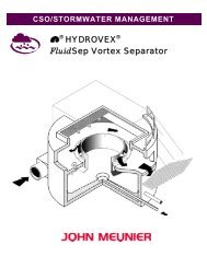
CSO/STORMWATER MANAGEMENT<br />
®<br />
HYDROVEX ®<br />
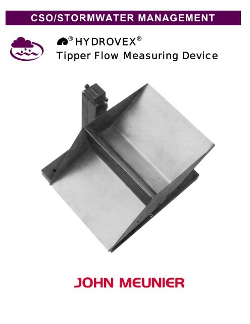
<strong>Tipper</strong> <strong>Flow</strong> <strong>Measuring</strong> <strong>Device</strong>
HYDROVEX ® TIPPER FLOW MEASURING DEVICE<br />
GENERAL<br />
Standard flow monitoring devices cannot readily perform the motoring of small and very small flows (for example, inductive flow<br />
meters or Venturi orifice units). The flow velocity becomes too low to ensure a sediment-free operation. In addition, monitoring of<br />
very irregular or even intermittent flows is not feasible.<br />
The HYDROVEX ® <strong>Tipper</strong> <strong>Flow</strong> <strong>Measuring</strong> <strong>Device</strong> is designed to collect small flows. The monitored flow can even fall to zero<br />
for a long period. However, over a certain period, an average flow is measured.<br />
The HYDROVEX ® <strong>Tipper</strong> <strong>Flow</strong> <strong>Measuring</strong> <strong>Device</strong> is a mechanical device requiring no external energy.<br />
OPERATION<br />
A filling pipe located right over the HYDROVEX ® <strong>Tipper</strong> fills the unit’s dual compartment semi-stable bucket. One of the two<br />
compartments is always in filling position, whereas the other is in tipped position and empty.<br />
As soon as the dripping liquid reaches the activation level of the compartment, the bucket tips and empties the liquid. The tipping<br />
takes place due to the displacement of the center of gravity of the filled bucket. The released liquid is drained to the outlet, while<br />
the dripping liquid starts filling the other compartment now in place.<br />
A mechanical counting device records each filling cycle. The number of counts, multiplied by the volume of the two<br />
compartments, gives the flow per unit of time. After inspection, the meter can be set back to zero.<br />
As an option, the unit can be fitted with a magnetic switch to detect each filling cycle. The switch must be linked to a small control<br />
system that will count the pulses and record the information. The magnetic switch can be supplied to meet explosion proof<br />
requirements.<br />
INSTALLATION<br />
To insure a long trouble-free operation, the base plate of the HYDROVEX ® <strong>Tipper</strong> must be anchored properly. For temporary<br />
installation, the unit can simply be installed in position. However, the unit will require regular visual inspection to guaranty that the<br />
unit has not moved at the tipping of the bucket. The filling pipe is set between ¾” and 1 ½” above the higher edge of the tipping<br />
bucket. Insuring a proper liquid drainage under the HYDROVEX ® <strong>Tipper</strong> is also mandatory.<br />
Figure 1: Construction of a HYDROVEX ® <strong>Tipper</strong> <strong>Flow</strong> <strong>Measuring</strong> <strong>Device</strong>
CONSTRUCTION<br />
The tipping bucket is in 304 Stainless Steel. The flushing angle is at 20º from the horizontal axis. This way, even highly loaded<br />
fluids can be reliably treated.<br />
The flow-measuring device is fitted with bearings on a stainless steel shaft safely located under the unit. The base plate and the<br />
supports are either made out of massive PVC or 304 Stainless Steel. The bumpers are made of special noise-reducing rubber.<br />
The mechanical meter is splash tight and corrosion resistant.<br />
APPLICATIONS<br />
The HYDROVEX ® <strong>Tipper</strong> <strong>Flow</strong> <strong>Measuring</strong> <strong>Device</strong> can be installed where measurements of small or very small flows with<br />
periodic stops and long monitoring must be carried out.<br />
<strong>Flow</strong>s produced by a single household, small industry, flow produced by roof or parking catchments are all good applications for<br />
the HYDROVEX ® <strong>Tipper</strong> <strong>Flow</strong> <strong>Measuring</strong> <strong>Device</strong>. Landfill or mine infiltration water or dam leaks can also use such a device.<br />
Volume by<br />
double fillings<br />
Maximum<br />
<strong>Flow</strong><br />
Length<br />
Width<br />
Height at<br />
inlet<br />
Overall<br />
height<br />
V Q max L B H Hges<br />
l m 3 /h (cfs) l/s (cfs) mm (in.) mm (in.) mm (inc.) mm (in.)<br />
10 4.5 (0.04) 1.3 (0.05) 385 (15.2") 490 (19.3") 350 (13.8") 375 (14.8")<br />
16 7.21 (0.1) 2 (0.07) 425 (16.7") 575 (22.6") 395 (15.6") 420 (16.5")<br />
25 11.3 (0.1) 3.2 (0.1) 480 (18.9") 660 (26.0") 440 (17.3") 465 (18.3")<br />
40 18 (0.2) 5 (0.2) 535 (21.1) 770 (30.3") 500 (20.0") 525 (20.7")<br />
Other dimensions upon request<br />
Table: Characteristics and dimensions of the HYDROVEX ® <strong>Tipper</strong> <strong>Flow</strong> <strong>Measuring</strong> <strong>Device</strong>
Manhole<br />
<strong>Tipper</strong> <strong>Flow</strong> <strong>Measuring</strong> <strong>Device</strong><br />
V = 10 I<br />
Section AA<br />
Section BB<br />
Water<br />
infiltration<br />
inlet<br />
Example of installation<br />
HYDROVEX ® <strong>Tipper</strong> V = 10 l in monitoring manhole for infiltration<br />
MATERIALS<br />
Measurement:<br />
Base Plate<br />
Switch support:<br />
Shaft Support<br />
Shaft and bearings:<br />
Bolt, nuts and anchors:<br />
Mechanical switch:<br />
Bumpers:<br />
304 Stainless Steel<br />
Massive PVC or 304 Stainless Steel<br />
304 Stainless Steel<br />
304 Stainless Steel<br />
Plastics and 304 Stainless Steel<br />
Special rubber resistant to waste water<br />
UNIT TYPICAL SPECIFICATION<br />
HYDROVEX ® <strong>Tipper</strong> <strong>Flow</strong> <strong>Measuring</strong> <strong>Device</strong> with dual compartment bucket;<br />
<strong>Measuring</strong> volume_________liters by double filling with mechanical switch.<br />
Options:<br />
With NEMA 4X magnetic switch<br />
With NEMA 4X magnetic switch with intrinsically safe relay in the control unit for Explosion Proof requirement.<br />
John Meunier Inc.<br />
ISO 9001 : 2000<br />
Head Office<br />
4105 Sartelon<br />
Saint-Laurent (Quebec) Canada H4S 2B3<br />
Tel.: 514-334-7230 www.johnmeunier.com<br />
Fax: 514-334-5070 cso@johnmeunier.com<br />
Ontario Office<br />
2000 Argentia Road, Plaza 4, Unit 430<br />
Mississauga (Ontario) Canada L5N 1W1<br />
Tel.: 905-286-4846 www.johnmeunier.com<br />
Fax: 905-286-0488 ontario@johnmeunier.com<br />
USA Office<br />
2209 Menlo Avenue<br />
Glenside, PA USA 19038<br />
Tel.: 412- 417-6614 www.johnmeunier.com<br />
Fax: 215-885-4741 asteele@johnmeunier.com<br />
Revised : 2008-10-01