AfM Technology Volumetric Compensation of machine tools
AfM Technology Volumetric Compensation of machine tools
AfM Technology Volumetric Compensation of machine tools

Create successful ePaper yourself
Turn your PDF publications into a flip-book with our unique Google optimized e-Paper software.
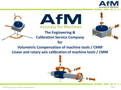
The Engineering &<br />
Calibration Service Company<br />
for<br />
<strong>Volumetric</strong> <strong>Compensation</strong> <strong>of</strong> <strong>machine</strong> <strong>tools</strong> / CMM<br />
Linear and rotary axis calibration <strong>of</strong> <strong>machine</strong> <strong>tools</strong> / CMM<br />
© <strong>AfM</strong> <strong>Technology</strong> GmbH / Wolfram Meyer<br />
Page 1
Aachen colloquium for 5-Axis precision machining<br />
Agenda<br />
• Geometric deviations <strong>of</strong> <strong>machine</strong> <strong>tools</strong><br />
• Metrological parameter aquisition<br />
• <strong>Compensation</strong> in the CNC control<br />
• Limitations in aquisition and compensation<br />
• Trends and challenges<br />
© <strong>AfM</strong> <strong>Technology</strong> GmbH / Wolfram Meyer<br />
Page 2
Aachen colloquium for 5-Axis precision machining<br />
Geometric deviations <strong>of</strong> <strong>machine</strong> <strong>tools</strong><br />
© <strong>AfM</strong> <strong>Technology</strong> GmbH / Wolfram Meyer<br />
Page 3
Influences on <strong>machine</strong> tool accuracy<br />
Drives<br />
Dynamic<br />
Geometry<br />
• Component<br />
deviations<br />
• Location deviations<br />
• Model fitness<br />
• Machine coordinate<br />
system<br />
Thermal<br />
influences<br />
© <strong>AfM</strong> <strong>Technology</strong> GmbH / Wolfram Meyer<br />
Page 4
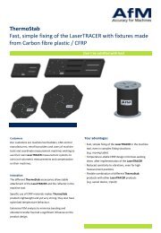
Geometric deviations on a linear <strong>machine</strong> axis<br />
Each linear guide has 6 degrees <strong>of</strong> freedom, 3 translational und 3 rotational<br />
translational movement<br />
(transverse to the guide axis) / EZX<br />
translational movement<br />
(transverse to the guide axis) EYX<br />
support<br />
rotational movement:<br />
around X = roll / EAX<br />
around Y = pitch / EBX<br />
around Z = yaw / ECX<br />
guide<br />
translational movement (position) / EXX<br />
© <strong>AfM</strong> <strong>Technology</strong> GmbH / Horst Eckersberger<br />
Page 5
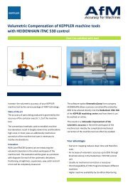
Geometric deviations on a rotary <strong>machine</strong> axis<br />
Each rotary axis has 6 degrees <strong>of</strong> freedom, 3 translational und 3 rotational<br />
translational movement (axial runout in Z) / EZC<br />
translational movement (radial runout in Y) / EYC<br />
support<br />
rotational movement:<br />
around X = wobble / EAC<br />
around Y = wobble / EBC<br />
around Z = position / ECC<br />
Rotary table<br />
translational movement (radial runout in X) / EXC<br />
© <strong>AfM</strong> <strong>Technology</strong> GmbH / Horst Eckersberger<br />
Page 6
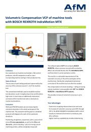
Kinematic chain <strong>of</strong> a <strong>machine</strong> tool<br />
Kinematic chain<br />
t – S – A – B – Y – Z – MB – X – C – MT – w<br />
Spindle<br />
Tool<br />
Machine<br />
base<br />
Work<br />
piece<br />
© <strong>AfM</strong> / Keppler<br />
Component dev.<br />
location dev.<br />
• 3 linear axes<br />
• 3 rotary axes<br />
• 1 spindle<br />
3 x 6 = 18<br />
3 x 6 = 18<br />
1 x 5 = 5<br />
3 x 3 = 9<br />
3 x 5 = 15<br />
1 x 4 = 4<br />
∑ = 69<br />
deviations<br />
• coordinate system<br />
- 6<br />
• Effective deviations<br />
41<br />
28<br />
© <strong>AfM</strong> <strong>Technology</strong> GmbH / Wolfram Meyer<br />
Page 7
Resulting errors at the tool center point (linear axes)<br />
Geometric errors<br />
• positioning error<br />
• straightness<br />
• roll<br />
• yaw<br />
• pitch<br />
• squareness<br />
Resulting error<br />
at TCP<br />
• positioning error<br />
• orientation error<br />
Programmed<br />
tool position<br />
and<br />
tool orientation<br />
Real<br />
tool<br />
orientation<br />
Real<br />
TCP<br />
position<br />
The geometrical errors <strong>of</strong> the linear axes <strong>of</strong> a 3-axes <strong>machine</strong> tool cause spatial errors <strong>of</strong> the TCP<br />
concerning position and orientation.<br />
© <strong>AfM</strong> <strong>Technology</strong> GmbH / Horst Eckersberger<br />
Page 8
Resulting errors at the tool center point (rotary axes)<br />
Geometric errors<br />
• runout<br />
• wobble<br />
• position<br />
• location <strong>of</strong> axis<br />
• orientation <strong>of</strong> axis<br />
• zero position<br />
Resulting error<br />
at TCP<br />
Real<br />
tool<br />
orientation<br />
Real<br />
TCP<br />
position<br />
• positioning error<br />
• orientation error<br />
The component and location errors <strong>of</strong> the radial axes <strong>of</strong> a 4/5/6-axes <strong>machine</strong> tool causes also<br />
spatial errors <strong>of</strong> the TCP concerning position and orientation.<br />
© <strong>AfM</strong> <strong>Technology</strong> GmbH / Wolfram Meyer<br />
Page 9
Aachen colloquium for 5-Axis precision machining<br />
Metrological parameter aquisition<br />
© <strong>AfM</strong> <strong>Technology</strong> GmbH / Wolfram Meyer<br />
Page 10
Measurement methods for error parameters<br />
Direct Measurement<br />
Indirect Measurement<br />
Component<br />
deviations<br />
• Laserinterferometer<br />
• Straightness artefact<br />
& indicator (Wire /<br />
Stone)<br />
• Levels<br />
• Reference encoders<br />
Reference scales<br />
• Autokollimator<br />
Location<br />
deviations<br />
• Laserinterferometer<br />
• 90° stone angle,<br />
calibration cube &<br />
dial indicator<br />
• Levels<br />
• Test mandrel & dial<br />
indicator<br />
Component and location<br />
deviations<br />
• Ball bar, ball plate, Tetraeder<br />
• Reference parts<br />
• Circular test<br />
• Ball & 3D-Probe<br />
• Lasertracker<br />
• LaserTRACER<br />
© <strong>AfM</strong> <strong>Technology</strong> GmbH / Wolfram Meyer<br />
Page 11
Direct measurement <strong>of</strong> linear axis with single-purpose <strong>tools</strong><br />
• A great variety <strong>of</strong> <strong>tools</strong> is used<br />
Levels<br />
Reference scales<br />
Straightness laser<br />
Autokollimator<br />
Straightness artefact & indicator (Wire / Stone)<br />
© <strong>AfM</strong> <strong>Technology</strong> GmbH / Wolfram Meyer<br />
Page 12
Direct measurement <strong>of</strong> linear axis with laser interferometer<br />
• Laserinterferometer available with 1 up to 6 DOF<br />
Renishaw (1-DOF)<br />
• High accurate, long range<br />
• Alignment effort, particularly for vertical and<br />
straightness measurement is high<br />
TSK (3-DOF)<br />
API (6-DOF)<br />
HP Agilent (1-DOF)<br />
© TSK<br />
© <strong>AfM</strong> <strong>Technology</strong> GmbH / Wolfram Meyer<br />
Page 13
Direct measurement <strong>of</strong> rotary axis<br />
Test mandrell<br />
HEIDENHAIN Reference encoder RON 905<br />
&<br />
dial indicator<br />
Laserinterferometer with Renishaw RX10<br />
API Swivelcheck<br />
© <strong>AfM</strong> <strong>Technology</strong> GmbH / Wolfram Meyer<br />
Page 14
Indirect measurement <strong>of</strong> linear axis with ball bars<br />
Renishaw QC-20W<br />
• Fast and easy measurement<br />
• Geometric and drive analysis<br />
• Applicable in any plane<br />
• Mind the volume size<br />
Dreier RoundCheck VA<br />
API Ballbar<br />
© <strong>AfM</strong> <strong>Technology</strong> GmbH / Wolfram Meyer<br />
Page 15
Indirect measurement <strong>of</strong> component and location deviation<br />
• Ball bars (1D), ball plates (2D), Tetraeder (3D)<br />
Ball plate<br />
• Fixed grid, limited dimension, handling complex<br />
Ball bar<br />
© Pr<strong>of</strong>. Knapp ETH Zürich<br />
Tetraeder<br />
© IBS Precision Engineering<br />
© Dr. Trapet<br />
© <strong>AfM</strong> <strong>Technology</strong> GmbH / Wolfram Meyer<br />
Page 16
Indirect measurement <strong>of</strong> linear axis with laser interferometer<br />
Optodyne MCV 500<br />
© Dr. Trapet<br />
© <strong>AfM</strong> <strong>Technology</strong> GmbH / Wolfram Meyer<br />
Page 17
Indirect measurement by multilateration with LaserTRACER<br />
• Linear axis calibration<br />
• Rotary axis calibration<br />
• Acceptance test according<br />
to ISO 230-2/4/6 and ISO<br />
10360-2<br />
LaserTRACER MT<br />
LaserTRACER<br />
© <strong>AfM</strong> <strong>Technology</strong> GmbH / Wolfram Meyer<br />
Page 18
Online multilateration with LaserTRACER<br />
What is Multilateration?<br />
• Ideal realization <strong>of</strong> the Abbe Principle: All measurement<br />
lines pass directly through the measurement point.<br />
• Principle is used in Global Positioning System (based on<br />
time <strong>of</strong> flight measurement).<br />
• With LaserTRACERs, the principle can be downscaled to<br />
submicron accuracy in a medium measurement volume.<br />
© Etalon<br />
• If four LaserTRACERs are used, the system is self calibrating<br />
Characteristics<br />
• Mobile, Self calibration<br />
• Contactless, 3D measure<br />
• Working volume up to 10 m x 10 m x 10 m.<br />
• Direct traceability by stabilized laser interferometer.<br />
• Highest resolution and accuracy (down to sub-micron range)<br />
© <strong>AfM</strong> <strong>Technology</strong> GmbH / Wolfram Meyer<br />
Page 19
3D Messung mit LaserTracker<br />
Moving<br />
Active Target (AT)<br />
Lasertracker<br />
Stationary<br />
T3 Laser Tracker<br />
(with Pan & Tilt)<br />
© API<br />
© <strong>AfM</strong> <strong>Technology</strong> GmbH / Wolfram Meyer<br />
Page 20
Rotary axis calibration with ball and 3D probe<br />
• Rotary and swivel axis as well as trunion table are<br />
supported<br />
Trunion Table Calibration<br />
• Fixed ball, moved probe or fixed probe and moved ball<br />
• Fast, easy and automatic cycle<br />
Up to 3 rotary axis at once<br />
Fork Head Calibration<br />
© HEIDENHAIN<br />
© Fidia<br />
© IBS Engineering Precision<br />
© <strong>AfM</strong> <strong>Technology</strong> GmbH / Wolfram Meyer<br />
Page 21
Aachen colloquium for 5-Axis precision machining<br />
<strong>Compensation</strong> in the CNC control<br />
© <strong>AfM</strong> <strong>Technology</strong> GmbH / Wolfram Meyer<br />
Page 22
Geometric compensations in CNC controllers<br />
Geometric compensations (stand alone or as combination)<br />
• Linear encoder error compensation (slope)<br />
• Non linear encoder error compensation (arbitrary form)<br />
• Cross error compensation<br />
• Grid compensation<br />
• <strong>Volumetric</strong> compensation<br />
Stand alone or as part <strong>of</strong> geometric compensation<br />
• Backlash compensation<br />
© <strong>AfM</strong> <strong>Technology</strong> GmbH / Wolfram Meyer<br />
Page 23
deviation [µm]<br />
0<br />
200<br />
400<br />
600<br />
800<br />
1000<br />
1200<br />
1400<br />
1600<br />
1800<br />
2000<br />
2200<br />
2400<br />
2600<br />
2800<br />
3000<br />
3200<br />
3400<br />
Linear and non linear encoder error compensation<br />
linear encoder error compensation (slope)<br />
100,0<br />
Position deviation y-axis<br />
80,0<br />
60,0<br />
40,0<br />
20,0<br />
0,0<br />
-20,0<br />
-40,0<br />
yTy / EYY<br />
Linear (yTy / EYY)<br />
Non linear encoder error compensation (arbitrary form)<br />
© <strong>AfM</strong> <strong>Technology</strong> GmbH / Wolfram Meyer<br />
Page 24
Cross error compensation<br />
• Crosstalk <strong>of</strong> any axis combination can be compensated<br />
• <strong>Compensation</strong> <strong>of</strong> straightness and squareness<br />
© HEIDENHAIN<br />
© <strong>AfM</strong> <strong>Technology</strong> GmbH / Wolfram Meyer<br />
Page 26
3D Grid compensation<br />
• The volume is divided in cubes or a spherical grid<br />
• Each corner <strong>of</strong> the cube is represent by an error vector<br />
• Used for linear axis as well as rotary axis<br />
∆X i<br />
∆Y i = f(A,C)<br />
∆Z i<br />
© Bosch Rexroth<br />
© Siemens © FANUC<br />
© <strong>AfM</strong> <strong>Technology</strong> GmbH / Wolfram Meyer<br />
Page 27
<strong>Volumetric</strong> compensation<br />
E = T e + R em * P m + R et * P t<br />
© <strong>AfM</strong> <strong>Technology</strong> GmbH / Wolfram Meyer<br />
Page 28
Backlash compensation<br />
Backlash compensation<br />
Backlash U / U1<br />
As single axis parameter<br />
z.B. Siemens 840D sl<br />
MD 32450 Backlash compensation<br />
$MA_BACKLASH[0]=0.002 mm<br />
As data set along the axis<br />
Position deviation B-Axis (forward & backward travel)<br />
20,0<br />
10,0<br />
0,0<br />
-29,0 -24,0 -19,0 -14,0 -9,0<br />
-10,0<br />
-4,0 1,0 6,0 11,0 16,0 21,0 26,0<br />
-20,0<br />
-30,0<br />
-40,0<br />
without CEC [0,001°] with CEC [0,001°]<br />
without CEC [0,001°] with CEC [0,001°]<br />
© <strong>AfM</strong> <strong>Technology</strong> GmbH / Wolfram Meyer<br />
Page 29
Aachen colloquium for 5-Axis precision machining<br />
Limitations in aquisition and compensation<br />
© <strong>AfM</strong> <strong>Technology</strong> GmbH / Wolfram Meyer<br />
Page 33
Limitation by model fitness (I)<br />
EZY (y,z)<br />
yTz (y,z)<br />
EAY (y,z)<br />
yRx (y,z)<br />
Crosstalking from Z-axis to Y-axis<br />
Y<br />
Z<br />
yTz = yTz(y) + Ytz(y,z) *z<br />
Z<br />
Y<br />
Z<br />
yRx = yRx(y) + yRxz(y,z) * z<br />
Y<br />
EZY = EZY(y) + EZYZ(y,z) *z<br />
EAY = EAY(y) + EAYZ(y,z) * z<br />
21 Error Model<br />
23 Error Model<br />
900<br />
800<br />
700<br />
600<br />
500<br />
400<br />
300<br />
200<br />
100<br />
0<br />
±3s ≈ ±30,6 µm<br />
1600<br />
1400<br />
1200<br />
1000<br />
800<br />
600<br />
400<br />
200<br />
0<br />
±3s ≈ ±18,3 µm<br />
© <strong>AfM</strong> <strong>Technology</strong> GmbH / Wolfram Meyer<br />
Page 34
deviation [µrad]<br />
deviation [µm/m]<br />
0<br />
0<br />
200<br />
400<br />
600<br />
800<br />
1000<br />
1200<br />
1400<br />
1600<br />
1800<br />
2000<br />
2200<br />
2400<br />
2600<br />
2800<br />
3000<br />
3200<br />
3400<br />
200<br />
400<br />
600<br />
800<br />
1000<br />
1200<br />
1400<br />
1600<br />
1800<br />
2000<br />
2200<br />
2400<br />
2600<br />
2800<br />
3000<br />
3200<br />
3400<br />
deviation [µrad/m]<br />
0<br />
200<br />
400<br />
600<br />
800<br />
1000<br />
1200<br />
1400<br />
1600<br />
1800<br />
2000<br />
2200<br />
2400<br />
2600<br />
2800<br />
3000<br />
3200<br />
3400<br />
Limitation by model fitness (II)<br />
20,0<br />
15,0<br />
10,0<br />
5,0<br />
0,0<br />
-5,0<br />
-10,0<br />
-15,0<br />
-20,0<br />
-25,0<br />
Pitch y-axis<br />
yRx / EAY with 21 model<br />
yRx / EAY with 23 model<br />
Squareness yWz / AOZ<br />
1,000000<br />
0,000000<br />
deviation [µrad]<br />
yWz/AOZ<br />
yWz/AOZ<br />
with 23 model<br />
Bending <strong>of</strong> Column<br />
Yaw <strong>of</strong> Column<br />
100,0<br />
90,0<br />
80,0<br />
70,0<br />
60,0<br />
50,0<br />
40,0<br />
30,0<br />
20,0<br />
10,0<br />
0,0<br />
-10,0<br />
30,0<br />
25,0<br />
20,0<br />
15,0<br />
10,0<br />
5,0<br />
0,0<br />
-5,0<br />
YTZZ with 21 model<br />
YTZZ with 23 model<br />
YRXZ with 21 model<br />
YRXZ with 23 model<br />
© <strong>AfM</strong> <strong>Technology</strong> GmbH / Wolfram Meyer<br />
Page 35
-0,0300<br />
-0,0270<br />
-0,0240<br />
-0,0210<br />
-0,0180<br />
-0,0150<br />
-0,0120<br />
-0,0090<br />
-0,0060<br />
-0,0030<br />
0,0000<br />
0,0030<br />
0,0060<br />
0,0090<br />
0,0120<br />
0,0150<br />
0,0180<br />
0,0210<br />
0,0240<br />
0,0270<br />
0,0300<br />
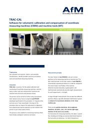
Limitation by volumetric backlash<br />
<strong>Volumetric</strong> backlash analysis<br />
Position 1 Position 2 Position 3 Position 4 Position 5 Position 6 Total<br />
Maximum 0,0187 0,0290 0,0170 0,0271 0,0142 0,0087 0,0087<br />
Minimum -0,0281 -0,0234 -0,0255 -0,0183 -0,0149 -0,0153 -0,0153<br />
Range 0,0468 0,0524 0,0426 0,0454 0,0290 0,0240 0,0240<br />
Std. dev. σ 0,0101 0,0119 0,0089 0,0092 0,0056 0,0061 0,0061<br />
±3σ (99,73%) 0,0607 0,0717 0,0532 0,0549 0,0338 0,0369 0,0369<br />
Drift 0,0000 0,0000 0,0000 0,0000 0,0000 0,0000 0,0000<br />
x̅ + 3σ 0,0303 0,0358 0,0266 0,0275 0,0169 0,0184 0,0184<br />
Average x̅ 0,0000 0,0000 0,0000 0,0000 0,0000 0,0000 0,0000<br />
x̅ - 3σ -0,0303 -0,0358 -0,0266 -0,0275 -0,0169 -0,0184 -0,0184<br />
180<br />
160<br />
140<br />
120<br />
100<br />
80<br />
60<br />
40<br />
20<br />
0<br />
Backlash distribution<br />
0,040<br />
0,030<br />
0,020<br />
0,010<br />
0,000<br />
-0,010<br />
-0,020<br />
-0,030<br />
-0,040<br />
Backlash single values<br />
1 26 51 76 101 126 151 176 201 226 251<br />
x̅ - 3σ x̅ + 3σ Pos1 Pos2<br />
Pos3 Pos4 Pos5 Pos6<br />
© <strong>AfM</strong> <strong>Technology</strong> GmbH / Wolfram Meyer <strong>Volumetric</strong> <strong>Compensation</strong> <strong>of</strong> <strong>machine</strong> <strong>tools</strong><br />
Page 36
10:15:00<br />
12:00:00<br />
13:45:00<br />
15:30:00<br />
17:15:00<br />
19:00:00<br />
20:45:00<br />
22:30:00<br />
00:15:00<br />
02:00:00<br />
03:45:00<br />
05:30:00<br />
07:15:00<br />
09:00:00<br />
10:45:00<br />
12:30:00<br />
14:15:00<br />
16:00:00<br />
17:45:00<br />
19:30:00<br />
21:15:00<br />
23:00:00<br />
00:45:00<br />
02:30:00<br />
04:15:00<br />
06:00:00<br />
07:45:00<br />
09:30:00<br />
11:15:00<br />
13:00:00<br />
14:45:00<br />
16:30:00<br />
18:15:00<br />
20:00:00<br />
21:45:00<br />
23:30:00<br />
01:15:00<br />
03:00:00<br />
04:45:00<br />
06:30:00<br />
08:15:00<br />
10:00:00<br />
11:45:00<br />
13:30:00<br />
15:15:00<br />
17:00:00<br />
18:45:00<br />
20:30:00<br />
22:15:00<br />
00:00:00<br />
01:45:00<br />
03:30:00<br />
05:15:00<br />
07:00:00<br />
Limitation by temperature conditions<br />
Temperature over time<br />
22,0<br />
21,0<br />
Calibration<br />
with AC-Head<br />
Calibration<br />
With AC-Head<br />
Verification<br />
With AC-Head<br />
Calibration<br />
W-Axis<br />
Verification<br />
W-Axis<br />
Calibration<br />
With Quill<br />
Verification with Quill<br />
20,0<br />
19,0<br />
18,0<br />
17,0<br />
16,0<br />
15,0<br />
14,0<br />
13,0<br />
X-Achse (min) [°C] X-Achse (max) [°C] Z-Achse [°C] Y-Achse (min) [°C] Y-Achse (max) [°C] Luft [°C]<br />
© <strong>AfM</strong> <strong>Technology</strong> GmbH / Wolfram Meyer <strong>Volumetric</strong> <strong>Compensation</strong> <strong>of</strong> <strong>machine</strong> <strong>tools</strong><br />
Page 37
Aachen colloquium for 5-Axis precision machining<br />
Trends and challenges<br />
© <strong>AfM</strong> <strong>Technology</strong> GmbH / Wolfram Meyer<br />
Page 38
Trends and challenges<br />
Kinematic measurement at once<br />
Dynamic data collection<br />
Online connection<br />
Thermal models for <strong>machine</strong>s<br />
MPE for volumetric accuracy<br />
Advanced kinematic error models<br />
© <strong>AfM</strong> <strong>Technology</strong> GmbH / Wolfram Meyer<br />
Page 39
Thank you for your attention<br />
Vielen Dank für Ihre Aufmerksamkeit<br />
Grazie per la vostra attenzione<br />
<strong>AfM</strong> <strong>Technology</strong> Italia Srl<br />
Via Giotto 25 / Giotto Straße 25<br />
39100 Bolzano / Bozen / Italy<br />
Fon/ Fax: +39 0471 911953<br />
Mobile: +39 348 4221124<br />
www.afm-tec.it • info@afm-tec.it<br />
<strong>AfM</strong> <strong>Technology</strong> GmbH<br />
Gartenstraße 133<br />
73430 Aalen / Germany<br />
Fon: +49 (0)7361 889608-0<br />
Fax: +49 (0)7361 889608-99<br />
www.afm-tec.de • info@afm-tec.de<br />
© <strong>AfM</strong> <strong>Technology</strong> GmbH / Wolfram Meyer<br />
Page 40