Wavetronix SmartSensor Matrix - Interprovincial Traffic Services
Wavetronix SmartSensor Matrix - Interprovincial Traffic Services
Wavetronix SmartSensor Matrix - Interprovincial Traffic Services

Create successful ePaper yourself
Turn your PDF publications into a flip-book with our unique Google optimized e-Paper software.
<strong>SmartSensor</strong> <strong>Matrix</strong><br />
<strong>SmartSensor</strong> <strong>Matrix</strong><br />
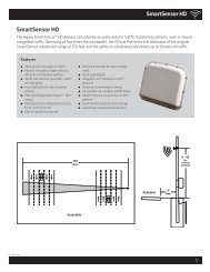
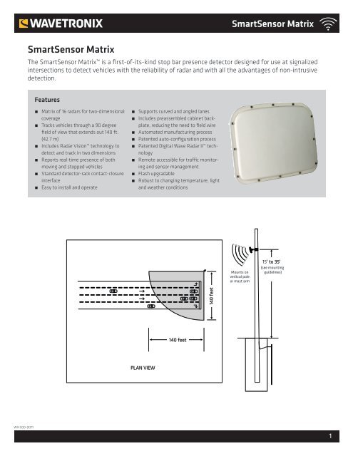
The <strong>SmartSensor</strong> <strong>Matrix</strong> is a first-of-its-kind stop bar presence detector designed for use at signalized<br />
intersections to detect vehicles with the reliability of radar and with all the advantages of non-intrusive<br />
detection.<br />
Features<br />
˿˿<br />
<strong>Matrix</strong> of 16 radars for two-dimensional<br />
coverage<br />
˿˿<br />
Tracks vehicles through a 90 degree<br />
field of view that extends out 140 ft.<br />
(42.7 m)<br />
˿˿<br />
Includes Radar Vision technology to<br />
detect and track in two dimensions<br />
˿˿<br />
Reports real-time presence of both<br />
moving and stopped vehicles<br />
˿˿<br />
Standard detector-rack contact-closure<br />
interface<br />
˿˿<br />
Easy to install and operate<br />
˿˿<br />
Supports curved and angled lanes<br />
˿˿<br />
Includes preassembled cabinet backplate,<br />
reducing the need to field wire<br />
˿˿<br />
Automated manufacturing process<br />
˿˿<br />
Patented auto-configuration process<br />
˿˿<br />
Patented Digital Wave Radar II technology<br />
˿˿<br />
Remote accessible for traffic monitoring<br />
and sensor management<br />
˿˿<br />
Flash upgradable<br />
˿˿<br />
Robust to changing temperature, light<br />
and weather conditions<br />
Mounts on<br />
veritcal pole<br />
or mast arm<br />
15' to 35'<br />
(see mounting<br />
guidelines)<br />
140 feet<br />
140 feet<br />
PLAN VIEW<br />
WX-500-0071<br />
1
<strong>SmartSensor</strong> <strong>Matrix</strong><br />
Technical Specifications<br />
Sensor Outputs<br />
˿˿<br />
Real-time presence data in 10 lanes<br />
˿˿<br />
Maximum number of zones: 16<br />
˿˿<br />
Maximum number of channels: 16<br />
˿˿<br />
User-selectable zone to channel mapping<br />
˿˿<br />
AND logic triggers the channel when all the selected zones are<br />
active<br />
˿˿<br />
OR logic used to combine multiple zones to a channel output<br />
˿˿<br />
Channel output extend and delay functionality<br />
˿˿<br />
Algorithms mitigate detections from wrong way or cross traffic<br />
˿˿<br />
Fail-safe mode for contact closure outputs if communication is<br />
lost<br />
Detectable Area<br />
˿˿<br />
Detection range: 6 to 140 ft. (1.8 to 42.7 m)<br />
˿˿<br />
Field of view: 90º<br />
˿˿<br />
Flexible lane configuration support including:<br />
̀̀<br />
Up to 10 lanes<br />
̀̀<br />
Curved lanes<br />
̀̀<br />
Islands and medians<br />
System Hardware<br />
˿˿<br />
A <strong>SmartSensor</strong> <strong>Matrix</strong> corner radar for each approach<br />
˿˿<br />
A traffic cabinet preassembled backplate with:<br />
̀̀<br />
AC/DC power conversion<br />
̀̀<br />
Surge suppression<br />
̀̀<br />
Terminal blocks for cable landing<br />
̀̀<br />
Communication connection points<br />
̀̀<br />
Cabinet side mount or rack mount<br />
˿˿<br />
Contact closure input file cards:<br />
̀̀<br />
2 or 4 channel<br />
̀̀<br />
Compatible with industry standard detector racks<br />
Maintenance<br />
˿˿<br />
No cleaning or adjustment necessary<br />
˿˿<br />
No battery replacement necessary<br />
˿˿<br />
Recalibration is not necessary<br />
˿˿<br />
Mean time between failures: 10 years (estimated based on<br />
manufacturing techniques)<br />
Physical Properties<br />
˿˿<br />
Weight: 4.2 lbs. (1.9 kg)<br />
˿˿<br />
Physical dimensions: 13.2 in. × 10.6 in. × 3.3 in. (33.5 cm x 26.9<br />
cm x 8.4 cm)<br />
˿˿<br />
Resistant to corrosion, fungus, moisture deterioration, and<br />
ultraviolet rays<br />
˿˿<br />
Enclosure: Lexan EXL polycarbonate<br />
Ordering Information<br />
<strong>SmartSensor</strong> <strong>Matrix</strong><br />
WX-SS-225<br />
ACCESSORIES<br />
WX-SS-KIT – <strong>Wavetronix</strong> Install Kit<br />
WX-SS-112/114 – Click 112/114 rack cards<br />
WX-SS-704-xxx/705 – <strong>SmartSensor</strong><br />
6-conductor cable<br />
WX-SS-611 – <strong>SmartSensor</strong> Mount<br />
WX-SS-B01-0002/3/4/5 – Intersection<br />
preassembled backplate AC/DC<br />
WX-SS-B02-0002/3 – Intersection<br />
preassembled rack<br />
WX-SS-710 – Sensor cable junction box<br />
<strong>Wavetronix</strong><br />
78 East 1700 South<br />
Provo, UT 84606<br />
801.734.7200<br />
sales@wavetronix.com<br />
www.wavetronix.com<br />
˿˿<br />
Outdoor weatherable: UL 746C<br />
˿˿<br />
Watertight by NEMA 250 standard<br />
˿˿<br />
NEMA 250 compliant for:<br />
̀̀<br />
External icing (clause 5.6)<br />
̀̀<br />
Hose down (clause 5.7)<br />
̀̀<br />
4X corrosion protection (clause 5.10)<br />
̀̀<br />
Gasket (clause 5.14)<br />
˿˿<br />
Withstands 5-ft. (1.5-m) drop<br />
˿˿<br />
Connector: MIL-C-26482<br />
˿˿<br />
Rotational backplate for 360º of roll<br />
Electrical<br />
˿˿<br />
Power consumption: 9 W<br />
˿˿<br />
Supply voltage: 9–28 VDC<br />
˿˿<br />
Onboard surge protection<br />
2 www. wavetronix.com
<strong>SmartSensor</strong> <strong>Matrix</strong><br />
Communication Ports<br />
˿˿<br />
Two half-duplex RS-485 com ports support:<br />
̀̀<br />
Dedicated detection comms<br />
̀̀<br />
Configuration, verification or traffic display without disrupting<br />
detection comms<br />
˿˿<br />
Firmware upgradability over any com port<br />
˿˿<br />
User configurable:<br />
̀̀<br />
Response delay<br />
̀̀<br />
Push port<br />
Radar Design<br />
˿˿<br />
Operating frequency: 24.0–24.25 GHz (K-band)<br />
˿˿<br />
<strong>Matrix</strong> of 16 radars<br />
˿˿<br />
No manual tuning to circuitry<br />
˿˿<br />
Transmits modulated signals generated digitally<br />
˿˿<br />
No temperature-based compensation necessary<br />
˿˿<br />
Bandwidth stable within 1%<br />
˿˿<br />
Printed circuit board antennas<br />
˿˿<br />
Antenna vertical 6 dB beam width (two-way pattern): 65°<br />
˿˿<br />
Horizontal field of view: 90º<br />
˿˿<br />
Antenna two-way sidelobes: -40 dB<br />
˿˿<br />
Transmit bandwidth: 245 MHz<br />
˿˿<br />
Un-windowed resolution: 2 ft. (0.6 m)<br />
˿˿<br />
RF channels: 8<br />
˿˿<br />
Self-test for verifying hardware functionality<br />
˿˿<br />
Diagnostics mode for verifying system functionality<br />
Configuration<br />
˿˿<br />
Automatic and manual configuration of lanes, stop bars and<br />
zones<br />
˿˿<br />
Lane positioning increment: 1 ft. (0.3 m)<br />
˿˿<br />
Four-sided zones of any shape and size<br />
˿˿<br />
Overlapping zones supported<br />
˿˿<br />
Sensor reconfiguration without detection disruption supported<br />
˿˿<br />
Graphical user interface with traffic pattern display<br />
˿˿<br />
Counting and Pulsed channels supported<br />
˿˿<br />
Windows Mobile®–compatible software<br />
˿˿<br />
Supported operating systems:<br />
̀̀<br />
Windows Mobile v5.0 or greater (Socket Mobile 650-M)<br />
̀̀<br />
Windows XP<br />
̀̀<br />
Windows Vista<br />
̀̀<br />
Windows 7<br />
˿˿<br />
Software-supported functionality:<br />
̀̀<br />
TCP/IP connectivity<br />
̀̀<br />
Sensor configuration back-up and restore<br />
̀̀<br />
Backed-up sensor configurations can be viewed and edited<br />
̀̀<br />
̀̀<br />
Real-time traffic visualization for performance verification<br />
and traffic display<br />
Zone and channel actuation display<br />
̀̀<br />
̀̀<br />
Virtual sensor connections for demonstration and training<br />
Local or remote sensor firmware upgradability<br />
Operating Conditions<br />
˿˿<br />
Accurate performance in:<br />
̀̀<br />
Rain up to 1 in. (2.5 cm) per hour<br />
̀̀<br />
Freezing rain<br />
̀̀<br />
Snow<br />
̀̀<br />
Wind<br />
̀̀<br />
Dust<br />
̀̀<br />
Fog<br />
̀̀<br />
Changing temperature<br />
̀̀<br />
Changing lighting (even direct light on sensor at dawn and<br />
dusk)<br />
˿˿<br />
Ambient operating temperature: -40°F to 165°F (-40°C to 74°C)<br />
˿˿<br />
Humidity: Up to 95% RH (non-condensing)<br />
Testing<br />
˿˿<br />
Tested under FCC CFR 47, part 15, section 15.249<br />
˿˿<br />
FCC certification on product label<br />
˿˿<br />
FCC regulation-compliant for life of the sensor<br />
˿˿<br />
Tested under IEC 61000-4-5 class 4<br />
˿˿<br />
Tested under NEMA TS 2-2003<br />
̀̀<br />
Shock pulses of 10 g, 11 ms half sine wave<br />
̀̀<br />
Vibration of 0.5 g up to 30 Hz<br />
̀̀<br />
300 V positive/negative pulses<br />
̀̀<br />
Stored at -49ºF (-45ºC) for 24 hours<br />
̀̀<br />
Stored at 185ºF (85ºC) for 24 hours<br />
̀̀<br />
Operation at -29.2ºF (-34ºC) and 10.8 VDC<br />
̀̀<br />
Operation at -29.2ºF (-34ºC) and 26.5 VDC<br />
̀̀<br />
Operation at 165.2ºF (74ºC) and 26.5 VDC<br />
̀̀<br />
Operation at 165.2ºF (74ºC) and 10.8 VDC<br />
Manufacturing<br />
˿˿<br />
Manufactured in the USA<br />
˿˿<br />
Surface mount assembly<br />
˿˿<br />
IPC-A-610C Class 2–compliant<br />
˿˿<br />
Operational testing:<br />
̀̀<br />
Sub-assembly test<br />
̀̀<br />
48-hour unit level burn-in<br />
̀̀<br />
Final unit test<br />
˿˿<br />
Unit test results available<br />
Support<br />
˿˿<br />
Training and tech support available from <strong>Wavetronix</strong><br />
˿˿<br />
<strong>Wavetronix</strong> training includes:<br />
̀̀<br />
̀̀<br />
Installation and configuration instruction to ensure accurate<br />
performance<br />
Classroom and in-field instruction<br />
3
<strong>SmartSensor</strong> <strong>Matrix</strong><br />
̀̀<br />
̀̀<br />
̀̀<br />
̀̀<br />
Knowledgeable trainers<br />
Use of presentation materials<br />
Virtual configuration using computer playback<br />
Instruction in use of computer and handheld devices and<br />
other necessary equipment<br />
˿˿<br />
<strong>Wavetronix</strong> tech support includes:<br />
̀̀<br />
̀̀<br />
Technical representatives available for installation and<br />
configuration<br />
Ongoing troubleshooting and maintenance support<br />
Documentation<br />
˿˿<br />
Instructional training guide<br />
˿˿<br />
Comprehensive user guide<br />
˿˿<br />
Installer quick-reference guide<br />
˿˿<br />
User quick-reference guide<br />
˿˿<br />
Documentation available upon request:<br />
̀̀<br />
FCC certification<br />
̀̀<br />
IEC 61000-4-5 class 4 test report<br />
Warranty<br />
˿˿<br />
Two-year warranty against material and workmanship defect<br />
The advertised detection accuracy of the company’s sensors is based on both external and internal testing, as outlined in each product’s specification<br />
document. Although our sensors are very accurate by industry standards, like all other sensor manufacturers we cannot guarantee perfection or assure<br />
that no errors will ever occur in any particular applications of our technology. Therefore, beyond the express Limited Warranty that accompanies each sensor<br />
sold by the company, we offer no additional representations, warranties, guarantees or remedies to our customers. It is recommended that purchasers<br />
and integrators evaluate the accuracy of each sensor to determine the acceptable margin of error for each application within their particular system(s).<br />
4 www. wavetronix.com
<strong>SmartSensor</strong> <strong>Matrix</strong><br />
<strong>SmartSensor</strong> <strong>Matrix</strong> Bid Specification<br />
1.0 General. This item shall govern the purchase of aboveground radar presence detector (RPD) equivalent to the <strong>Wavetronix</strong><br />
<strong>SmartSensor</strong> <strong>Matrix</strong>.<br />
An RPD detects vehicles by transmitting electromagnetic radar signals through the air. The signals bounce off vehicles in their<br />
paths and part of the signal is returned to the RPD. The returned signals are then processed to determine traffic parameters.<br />
RPDs are not affected by normal weather and environmental conditions such as rain, wind, snow, dust, etc. They also do not<br />
require cleaning and can maintain performance over a wide range of ambient temperatures.<br />
RPDs provide a non-intrusive means of detecting traffic. This property not only makes them safer to install but also more cost<br />
effective than sensors that require roadway modifications or placement.<br />
2.0 Sensor Outputs. The RPD shall present real-time presence data in 10 lanes.<br />
The RPD shall support a minimum of eight zones.<br />
The RPD shall support a minimum of four channels.<br />
The RPD shall support user-selectable zone to channel mapping.<br />
The RPD shall use AND logic to trigger channels when all selected zones are active.<br />
The RPD shall use OR logic to combine multiple zones to a channel output, and shall have channel output extend and delay<br />
functionality.<br />
The RPD algorithms shall mitigate detections from wrong way or cross traffic.<br />
The RPD system shall have fail-safe mode capabilities for contact closure outputs if communication is lost.<br />
3.0 Detectable Area.<br />
3.1 Detection Range. The RPD shall be able to detect and report presence in lanes with boundaries as close as 6 ft. (1.8 m)<br />
from the base of the pole on which the RPD is mounted.<br />
The RPD shall be able to detect and report presence in lanes located within the 140 ft. (42.7 m) arc from the base of the<br />
pole on which the RPD is mounted.<br />
3.2 Field of View. The RPD shall be able to detect and report presence for vehicles within a 90 degree field of view.<br />
3.3 Lane Configuration. The RPD shall be able to detect and report presence in up to 10 lanes.<br />
The RPD shall be able to detect and report presence in curved lanes and areas with islands and medians.<br />
4.0 System Hardware. For each approach to be detected, one RPD corner radar shall be used.<br />
4.1 Preassembled Backplate. Each RPD shall have a traffic cabinet preassembled backplate with the following:<br />
• AC/DC power conversion<br />
• Surge protection<br />
• Terminal blocks for cable landing<br />
• Communication connection points<br />
The preassembled backplate for the RPD shall be a cabinet side mount or rack mount.<br />
5
<strong>SmartSensor</strong> <strong>Matrix</strong><br />
4.2 Contact Closure Input File Cards. The RPD shall use contact closure input file cards with 2 or 4 channel capabilities.<br />
The contact closure input file cards for the RPD shall be compatible with industry standard detector racks.<br />
5.0 Maintenance. The RPD shall not require cleaning or adjustment to maintain performance.<br />
The RPD shall not rely on battery backup to store configuration information, thus eliminating any need for battery replacement.<br />
Once the RPD is calibrated, it shall not require recalibration to maintain performance unless the roadway configuration changes.<br />
The mean time between failures shall be 10 years, which is estimated based on manufacturing techniques.<br />
6.0 Physical Properties. The RPD shall not exceed 4.2 lbs. (1.9 kg) in weight.<br />
The RPD shall not exceed 13.2 in. by 10.6 in. by 3.3 in. (33.5 cm x 26.9 cm x 8.4 cm) in its physical dimensions.<br />
All external parts of the RPD shall be ultraviolet-resistant, corrosion-resistant, and protected from fungus growth and moisture<br />
deterioration.<br />
6.1 Enclosure. The RPD shall be enclosed in a Lexan EXL polycarbonate.<br />
The enclosure shall be classified “f1” outdoor weatherability in accordance with UL 746C.<br />
The RPD shall be classified as watertight according to the NEMA 250 standard.<br />
The RPD enclosure shall conform to test criteria set forth in the NEMA 250 standard for type 4X enclosures. Test results<br />
shall be provided for each of the following type 4X criteria:<br />
• External icing (NEMA 250 clause 5.6)<br />
• Hose-down (NEMA 250 clause 5.7)<br />
• 4X corrosion protection (NEMA 250 clause 5.10)<br />
• Gasket (NEMA 250 clause 5.14)<br />
The RPD shall be able to withstand a drop of up to 5 ft. (1.5 m) without compromising its functional and structural integrity.<br />
The RPD enclosure shall include a connector that meets the MIL-C-26482 specification. The MIL-C-26482 connector<br />
shall provide contacts for all data and power connections.<br />
7.0 Electrical. The RPD shall consume less than 10 W.<br />
The RPD shall operate with a DC input between 9 VDC and 28 VDC.<br />
The RPD shall have onboard surge protection.<br />
8.0 Communication Ports. The RPD shall have two communication ports, and both ports shall communicate independently and<br />
simultaneously.<br />
Two independent communication ports allow one port to be used for configuration, verification and traffic monitoring without<br />
interrupting communications on the dedicated data port.<br />
The RPD shall support the upload of new firmware into the RPD’s non-volatile memory over either communication port.<br />
The RPD shall support the user configuration of the following:<br />
• Response delay<br />
• Push port<br />
6 www. wavetronix.com
<strong>SmartSensor</strong> <strong>Matrix</strong><br />
The communication ports shall support a 9600 bps baud rate.<br />
9.0 Radar Design. The RPD shall be designed with a matrix of 16 radars.<br />
The matrix of 16 radars enables the sensor to provide detection over a large area and to discriminate lanes.<br />
9.1 Frequency Stability. The circuitry shall be void of any manual tuning elements that could lead to human error and<br />
degraded performance over time.<br />
All transmit modulated signals shall be generated by means of digital circuitry, such as a direct digital synthesizer, that is<br />
referenced to a frequency source that is at least 50 parts per million (ppm) stable over the specified temperature range, and<br />
ages less than 6 ppm per year. Any upconversion of a digitally generated modulated signal shall preserve the phase stability<br />
and frequency stability inherent in the digitally generated signal.<br />
This specification ensures that, during operation, the RPD strictly conforms to FCC requirements and that the radar signal<br />
quality is maintained for precise algorithmic quality. Analog and microwave components within an RPD have characteristics<br />
that change with temperature variations and age. If the output transmit signal is not referenced to a stable frequency<br />
source, then the RPD is likely to experience unacceptable frequency variations which may cause it to transmit out of its<br />
FCC allocated band and thus will be non-compliant with FCC regulations.<br />
The RPD shall not rely on temperature compensation circuitry to maintain transmit frequency stability.<br />
Temperature-based compensation techniques have been shown to be insufficient to ensure transmit frequency stability.<br />
One reason this type of technique is not sufficient is that it does not compensate for frequency variations due to component<br />
aging.<br />
The bandwidth of the transmit signal of the RPD shall not vary by more than 1% under all specified operating conditions<br />
and over the expected life of the RPD.<br />
The bandwidth of an RPD directly affects the measured range of a vehicle. A change in bandwidth causes a direct error in<br />
the measured range, i.e., a 5% change in bandwidth would cause a range error of 10 ft. (3 m) for a vehicle at 200 ft. (61 m).<br />
If the bandwidth changes by more than 1% due to seasonal temperature variations and component aging, then the RPD<br />
will need to be frequently reconfigured to maintain the specified accuracy.<br />
9.2 Antenna Design. The RPD antennas shall be designed on printed circuit boards.<br />
Printed circuit board antennas eliminate the need for RF connectors and cabling that result in decreased reliability. Printed<br />
circuit antennas are less prone to physical damage due to their extremely low mass.<br />
The vertical beam width of the RPD at the 6 dB points of the two-way pattern shall be 65 degrees or greater.<br />
The antennas shall cover a 90 degree horizontal field of view.<br />
The sidelobes in the RPD two-way antenna pattern shall be -40 dB or less.<br />
Low sidelobes ensure that the performance from the antenna beam widths is fully achieved.<br />
9.3 Resolution. The RPD shall transmit a signal with a bandwidth of at least 245 MHz.<br />
The bandwidth of the transmit signal translates directly into radar resolution, which contributes directly to detection<br />
performance. For example, an RPD that transmits at a low bandwidth will have low radar resolution, which could cause it<br />
to count a single vehicle as two vehicles in adjacent lanes. As another example of the adverse effects of low radar resolution,<br />
the response from a sign or other radar target in the roadway may spill over into the lanes of travel and desensitize the<br />
radar. In order to achieve the specified detection accuracy in a variety of conditions, the unwindowed radar resolution cannot<br />
be larger than 2 ft. (0.6 m) at the half-power level, which requires a bandwidth of 240 MHz. The high radar resolution<br />
7
<strong>SmartSensor</strong> <strong>Matrix</strong><br />
reduces the problem of vehicle responses getting drowned out by brighter vehicles in adjacent lanes and improves performance<br />
for moving and stopped vehicles near roadway targets.<br />
9.4 RF Channels. The RPD shall provide at least 8 RF channels so that multiple units can be mounted in the same vicinity<br />
without causing interference between them.<br />
9.5 Verification. The RPD shall have a self-test that is used to verify correct hardware functionality.<br />
The RPD shall have a diagnostics mode to verify correct system functionality.<br />
10.0 Configuration.<br />
10.1 Auto-configuration. The RPD shall have a method for automatically defining traffic lanes, stop bars and zones without<br />
requiring user intervention. This auto-configuration process shall execute on a processor internal to the RPD and shall<br />
not require an external PC or other processor.<br />
The auto-configuration process shall work under normal intersection operation and may require several cycles to complete.<br />
10.2 Manual Configuration. The auto-configuration method shall not prohibit the ability of the user to manually adjust<br />
the RPD configuration.<br />
The RPD shall support the configuring of lanes, stop bars and detection zones in 1-ft. (0.3-m) increments.<br />
When lanes have variable widths or have variable spacing (e.g. gore between lanes), precise resolution is necessary.<br />
10.3 Windows® Mobile-based Software. The RPD shall include graphical user interface software that displays all configured<br />
lanes and the current traffic pattern using a graphical traffic representation.<br />
A visual representation of traffic patterns allows an installer to quickly associate specific detections with corresponding<br />
vehicles, and it facilitates verification of RPD performance.<br />
The RPD shall include the ability to do counting and pulsed channels.<br />
The graphical interface shall operate on Windows Mobile, Windows XP, Windows Vista and Windows 7 in the .NET<br />
framework.<br />
The software shall support the following functionality:<br />
• Operate over a TCP/IP connection<br />
• Give the operator the ability to save/back up the RPD configuration to a file or load/restore the RPD configuration<br />
from a file<br />
• Allow the backed-up sensor configurations to be viewed and edited<br />
• Provide zone and channel actuation display<br />
• Provide a virtual connection option so that the software can be used without connecting to an actual sensor<br />
• Local or remote sensor firmware upgradability<br />
11.0 Operating Conditions. The RPD shall maintain accurate performance in all weather conditions, including rain, freezing<br />
rain, snow, wind, dust, fog and changes in temperature and light, including direct light on sensor at dawn and dusk.<br />
RPD operation shall continue in rain up to 1 in. (2.5 cm) per hour.<br />
The RPD shall be capable of continuous operation over an ambient temperature range of -40°F to 165.2°F (-40°C to 74°C).<br />
The RPD shall be capable of continuous operation over a relative humidity range of 5% to 95% (non-condensing).<br />
12.0 Testing.<br />
8 www. wavetronix.com
<strong>SmartSensor</strong> <strong>Matrix</strong><br />
12.1 FCC. Each RPD shall be certified by the Federal Communications Commission (FCC) under CFR 47, part 15, section<br />
15.249 as an intentional radiator.<br />
The FCC certification shall be displayed on an external label on each RPD according to the rules set forth by the FCC.<br />
The RPD shall comply with FCC regulations under all specified operating conditions and over the expected life of the<br />
RPD.<br />
12.2 NEMA TS 2-2003 Testing. The RPD shall comply with the applicable standards stated in the NEMA TS 2-2003<br />
standard. Third party test results shall be made available for each of the following tests:<br />
• Shock pulses of 10 g, 11 ms half sine wave<br />
• Vibration of 0.5 g up to 30 Hz<br />
• 300 V positive/negative pulses applied at one pulse per second at minimum and maximum DC supply voltage<br />
• Cold temperature storage at -49°F (-45°C) for 24 hours<br />
• High temperature storage at 185°F (85°C) for 24 hours<br />
• Low temp, low DC supply voltage at -29.2°F (-34°C) and 10.8 VDC<br />
• Low temp, high DC supply voltage at -29.2°F (-34°C) and 26.5 VDC<br />
• High temp, high DC supply voltage at 165.2°F (74°C) and 26.5 VDC<br />
• High temp, low DC supply voltage at 165.2°F (74°C) and 10.8 VDC<br />
13.0 Manufacturing. The RPD shall be manufactured and assembled in the USA.<br />
The internal electronics of the RPD shall utilize automation for surface mount assembly, and shall comply with the requirements<br />
set forth in IPC-A-610C Class 2, Acceptability of Electronic Assemblies.<br />
The RPD shall undergo a rigorous sequence of operational testing to ensure product functionality and reliability. Testing shall<br />
include the following:<br />
• Functionality testing of all internal sub-assemblies<br />
• Unit level burn-in testing of 48 hours’ duration or greater<br />
• Final unit functionality testing prior to shipment<br />
Test results and all associated data for the above testing shall be provided for each purchased RPD by serial number, upon request.<br />
14.0 Support. The RPD manufacturer shall provide both training and technical support services.<br />
14.1 Training. The manufacturer-provided training shall be sufficient to fully train installers and operators in the installation,<br />
configuration, and use of the RPD to ensure accurate RPD performance.<br />
The manufacturer-provided training shall consist of comprehensive classroom labs and hands-on, in-the-field, installation<br />
and configuration training.<br />
Classroom lab training shall involve presentations outlining and defining the RPD, its functions, and the procedures for<br />
proper operation. These presentations shall be followed by hands-on labs in which trainees shall practice using the equipment<br />
to calibrate and configure a virtual RPD. To facilitate the classroom presentation and handson labs, the manufacturer-provided<br />
training shall include the following items:<br />
• Knowledgeable trainer or trainers thoroughly familiar with the RPD and its processes<br />
• Presentation materials, including visual aids, printed manuals and other handout materials for each student<br />
• Computer files, including video and raw data, to facilitate the virtual configuration of the RPD<br />
• Laptop computers or Windows CE handheld devices with the necessary software, and all necessary cables, connectors,<br />
etc.<br />
• All other equipment necessary to facilitate the virtual configuration of the RPD<br />
Field training shall provide each trainee with the hands-on opportunity to install and configure the RPD at roadside.<br />
9
<strong>SmartSensor</strong> <strong>Matrix</strong><br />
Training shall be such that each trainee will mount and align the RPD correctly.<br />
14.2 Technical Assistance. Manufacturer-provided technical support shall be available according to contractual agreements,<br />
and a technical representative shall be available to assist with the physical installation, alignment, and auto-configuration<br />
of each supplied RPD. Technical support shall be provided thereafter to assist with troubleshooting, maintenance, or<br />
replacement of RPDs should such services be required.<br />
15.0 Documentation. RPD documentation shall include an instructional training guide and a comprehensive user guide as well<br />
as an installer quick-reference guide and a user quick-reference guide.<br />
The RPD manufacturer shall supply the following documentation and test results at the time of the bid submittal:<br />
• FCC CFR 47 certification (frequency compliance)<br />
• IED 6100-4-5 class 4 test report (surge)<br />
16.0 Warranty. The RPD shall be warranted free from material and workmanship defects for a period of two years from date of<br />
shipment.<br />
The advertised detection accuracy of the company’s sensors is based on both external and internal testing, as outlined in each product’s<br />
specification document. Although our sensors are very accurate by industry standards, like all other sensor manufacturers we cannot<br />
guarantee perfection or assure that no errors will ever occur in any particular applications of our technology. Therefore, beyond the express<br />
Limited Warranty that accompanies each sensor sold by the company, we offer no additional representations, warranties, guarantees or<br />
remedies to our customers. It is recommended that purchasers and integrators evaluate the accuracy of each sensor to determine the acceptable<br />
margin of error for each application within their particular system(s).<br />
10 www. wavetronix.com
<strong>SmartSensor</strong> <strong>Matrix</strong><br />
<strong>SmartSensor</strong> <strong>Matrix</strong> Installation Specification<br />
1.0 General. This item shall govern the installation of an aboveground radar presence detector (RPD) equivalent to the <strong>Wavetronix</strong><br />
<strong>SmartSensor</strong> <strong>Matrix</strong>.<br />
RPDs can provide accurate, consistent, and reliable presence detections provided they are installed properly. The requirements in<br />
this specification are intended to ensure proper RPD installation.<br />
2.0 Mounting and Installation.<br />
2.1 Mounting Assembly. The RPD shall be mounted directly onto a mounting assembly fastened to a mast arm, pole or<br />
other solid structure.<br />
The RPD mounting assembly shall provide the necessary degrees of rotation to ensure proper installation.<br />
The RPD mounting assembly shall be constructed of weather-resistant materials and shall be able to support a 20-lb. (9.1-<br />
kg) load.<br />
2.2 Mounting Location. The RPD shall be mounted at a height that is within the manufacturer’s recommended mounting<br />
heights.<br />
The RPD shall be mounted at an offset from the first lane that is consistent with the RPD’s minimum offset.<br />
The RPD shall be mounted so that at least 20 feet along the farthest lane to be monitored is within the field view of the<br />
RPD.<br />
The RPD shall be mounted with its cable connector down and shall be tilted so that the RPD is aimed at the center of the<br />
lanes to be monitored. Typically, the RPD is tilted off of vertical by 20–30 degrees.<br />
The RPD shall be mounted on a vertical signal pole or on the horizontal mast arm.<br />
The RPD shall be mounted so that its field of view is not occluded by poles, signs or other structures.<br />
RPDs that are mounted within 20 ft. (6.1 m) of each other or that are monitoring the same intersection shall be configured<br />
to operate on different RF channels regardless of the pointing direction of the RPDs.<br />
It is recommended that the manufacturer be consulted to verify final RPD placement if the RPD is to be mounted near<br />
large planar surfaces (sound barrier, building, parked vehicles, etc.) that run parallel to the monitored roadway.<br />
2.3 Cabling. The cable end connector shall meet the MILC- 26482 specification and shall be designed to interface with<br />
the appropriate MIL-C-26482 connector. The connector backshell shall be an environmentally sealed shell that offers<br />
excellent immersion capability. All conductors that interface with the connector shall be encased in a single jacket, and the<br />
outer diameter of this jacket shall be within the backshell’s cable O.D. range to ensure proper sealing. The backshell shall<br />
have a strain relief with enough strength to support the cable slack under extreme weather conditions. Recommended connectors<br />
are Cannon’s KPT series, and recommended backshells are Glenair Series 37 cable sealing backshells.<br />
The cable shall be the Orion Wire Combo-2204-2002-PVCGY or an equivalent cable that conforms to the following<br />
specifications:<br />
• The RS-485 conductors shall be a twisted pair.<br />
• The RS-485 conductors shall have nominal capacitance conductor to conductor of less than 40 pF/ft at 1 kHz.<br />
• The RS-485 conductors shall have nominal conductor DC resistance of less than 16.7 ohms/1000 ft. (304.8 m) at<br />
68°F (20°C).<br />
• The power conductors shall be one twisted pair with nominal conductor DC resistance of less than 11.5 ohms/1000 ft.<br />
11
<strong>SmartSensor</strong> <strong>Matrix</strong><br />
(304.8 m) at 68°F (20°C).<br />
• Each wire bundle or the entire cable shall be shielded with an aluminum/mylar shield with a drain wire.<br />
The cable shall be terminated only on the two farthest ends of the cable.<br />
The cable length shall not exceed 2000 ft (609.6 m) for the operational baud rate of RS-485 communications (9.6 Kbps).<br />
If 12 VDC is being supplied for the RPD then the cable length shall not exceed 110 ft. (33.5 m).<br />
If 24 VDC is being supplied for the RPD then the cable length shall not exceed 600 ft. (182.9 m).<br />
Both communication and power conductors can be bundled together in the same cable as long as the abovementioned<br />
conditions are met.<br />
2.4 In Cabinet Interface Equipment. The RPD shall be installed using the <strong>SmartSensor</strong> <strong>Matrix</strong> Preassembled <strong>Traffic</strong><br />
Cabinet Backplate or an equivalent that provides input power surge suppression, sensor cable surge suppression, AC to DC<br />
power conversion (if necessary), and terminal blocks. The surge protection devices shall meet or exceed the EN 61000-4-5<br />
Class 4 specifications.<br />
2.5 Power Supply. If needed, the RPD shall be installed using the Click 202, Click 204 or an equivalent AC to DC<br />
power converter that meets the following specifications:<br />
The power converter shall be power rated at 48 W for temperatures less than 140°F (60°C) with a 5% power decrease for<br />
each degree increase up to 158°F (70°C).<br />
The power converter shall operate in the temperature range of to -29.2°F to 165.2°F (–34°C to 74°C).<br />
The power converter shall operate in the humidity range of 5% to 95% at 77°F (25°C) non-condensing.<br />
The power converter shall accept an input voltage of 85 to 264 VAC or 120 to 370 VDC.<br />
The power converter shall operate at an input frequency of 47 Hz to 63 Hz.<br />
The power converter shall produce an output voltage of 24 VDC ±4%.<br />
The power converter shall withstand a voltage across its input and output of 2 kV. The power converter shall withstand a<br />
voltage across its input and ground of 1.5 kV.<br />
The power converter shall conform to safety standards UL 60950 and EN 60950.<br />
The power converter shall conform to EMC standards EN 55022 Class B and EN 61000-3-2, 3.<br />
In brown-out conditions (i.e. < 85 VAC input), the output voltage of the power converter shall be less than 1 VDC.<br />
The terminal blocks shall be color-coded insulation displacement terminal blocks.<br />
The terminal blocks shall be prewired to the other in-cabinet equipment so that no wiring other than cable terminations,<br />
connecting input power and connecting input file cards shall be required during installation.<br />
2.6 Input File Cards. The Click 114, Click 112 or an equivalent that meets the following specifications shall be used.<br />
The input file cards shall be compatible with 170, 2070, NEMA TS 1, and NEMA TS 2 style input racks.<br />
The input file card shall translate data packets from the RPD into contact closure outputs.<br />
The input file card shall support presence detection.<br />
12 www. wavetronix.com
<strong>SmartSensor</strong> <strong>Matrix</strong><br />
The input file card shall receive data packets over an RS-485 bus at a baud rate of 9600 bps.<br />
The input file card shall autobaud and auto-detect an RPD over wired and wireless communication channels that have a<br />
maximum latency of 500 ms.<br />
The input file card shall comply with the NEMA TS 2-1998 <strong>Traffic</strong> Controller Assemblies with NTCIP Requirements<br />
(Section 2.8 specification).<br />
13