Product Catalogue 2013
Product Catalogue 2013
Product Catalogue 2013

Create successful ePaper yourself
Turn your PDF publications into a flip-book with our unique Google optimized e-Paper software.
<strong>Product</strong> <strong>Catalogue</strong> <strong>2013</strong>
Table of Contents<br />
LK Armatur - A One-Stop Supplier.............. 5<br />
Loading Units.......................................................... 9<br />
LK 810 ThermoMat G.................................................. 10<br />
LK 810 ThermoMat G Eco.......................................... 13<br />
LK 810 ThermoMat W................................................ 16<br />
LK 810 ThermoMat W Eco.......................................... 19<br />
LK 811 ThermoMat E Eco............................................ 22<br />
LK 815 ThermoKit T Eco.............................................. 25<br />
LK 816 ThermoKit E Eco.............................................. 27<br />
Thermic Valves and Check Valves................ 29<br />
LK 820 ThermoVar....................................................... 30<br />
LK 821 ThermoVar...................................................... 34<br />
LK 823 ThermoVar........................................................ 38<br />
LK 825 ThermoVar........................................................ 40<br />
LK 822 ThermoBac...................................................... 43<br />
LK 826 ThermoBac....................................................... 45<br />
LK Insulation................................................................... 47<br />
Applications............................................................. 48<br />
Mixing Valves........................................................... 49<br />
LK 830 ThermoMix B................................................... 50<br />
LK 831 ThermoMix B.................................................... 52<br />
LK 840 ThermoMix........................................................ 54<br />
LK 841 ThermoMix........................................................ 57<br />
LK 845 ThermoMix........................................................ 60<br />
LK 846 ThermoMix........................................................ 62<br />
LK 850 ThermoMix H................................................... 64<br />
LK 851 ThermoMix H.................................................... 66<br />
LK 842 ThermoMix P..................................................... 68<br />
LK Insulation................................................................... 70<br />
Temperature Controllers................................. 71<br />
LK 100 SmartComfort CT............................................ 72<br />
LK 110 SmartComfort.................................................. 74<br />
LK 120 SmartComfort.................................................. 76<br />
LK 130 SmartComfort.................................................. 78<br />
Applications............................................................. 82<br />
Differential Temperature Controllers..... 83<br />
LK 150 SmartSol............................................................. 84<br />
LK 160 SmartBio............................................................ 86<br />
Solar Pump Units................................................... 89<br />
LK 201 SmartSolar....................................................... 90<br />
LK 202 SmartSolar........................................................ 92<br />
Mounting Kits.......................................................... 94<br />
Valve Actuators...................................................... 95<br />
LK 950 Valve Actuator.................................................. 96<br />
MultiFill®................................................................... 99<br />
LK 520 MultiFill® 25....................................................100<br />
LK 520 MultiFill® 32....................................................102<br />
Applications............................................................104<br />
Zone Valves.............................................................105<br />
LK 525 MultiZone 2V..................................................106<br />
LK 525 MultiZone 3V..................................................108<br />
LK 525 MultiZone Polar...............................................110<br />
LK 525 MultiZone Solar................................................112<br />
Applications............................................................114<br />
Other Valves.............................................................115<br />
LK 514 MultiSafe..........................................................117<br />
LK 548 AquaKit.............................................................118<br />
LK 550 AquaMix...........................................................120<br />
LK 538 ThermoFill EA...................................................122<br />
LK 539 ThermoFill EA...................................................124<br />
LK 435 OptiFlow............................................................125<br />
LK 519 ThermoSafe.......................................................127<br />
LK 700/705 AeroMat...................................................128<br />
Transition Fittings............................................................129<br />
Assembly Instructions for Compression Fittings......130<br />
Media..............................................................................130<br />
The LK Group............................................................131<br />
3
4<br />
Garnisonsgatan 49 • SE-254 66 Helsingborg • Sweden<br />
Phone: +46 (0)42-16 92 00 • Fax: +46 (0)42-16 92 20<br />
info@lkarmatur.se • order@lkarmatur.se<br />
www.lkarmatur.se
LK Armatur - A One-Stop Supplier<br />
Our Company<br />
LK Armatur was founded in 1985 when the LK Group widened<br />
its focus to provide heating system and calorifier manufacturers<br />
with valves and components.<br />
By constant development and response to market demand for<br />
new products and services, LK Armatur has grown to become<br />
an important supplier of valves, components and prefabricated<br />
units for the global OEM and distributor market. LK Armatur<br />
now produces more than one and a half million valves per year,<br />
ranging from simple standard valves to sophisticated, customized<br />
special products.<br />
We focus on customers who see energy saving and environmental<br />
awareness as a matter of course. The risk of energy<br />
shortage, the steady increase in energy prices and the problem<br />
of global warming have created a great need for cost and<br />
energy efficient heating systems in which renewable energy<br />
sources can be utilized. The common denominator for our<br />
customers is their stringent requirements for quality,<br />
customization and delivery reliability.<br />
Our aim is to be a complete business partner within the<br />
HVAC sector. This is why offering high quality products is<br />
not enough - the products must also be in the right place at<br />
the right time. We have made it our priority to accept general<br />
responsibility for logistics and we make sure that our deliveries<br />
arrive at our customer’s workplace at the right time, clearly<br />
marked and packaged as per request. In this way we contribute<br />
to lowering our customers’ production costs.<br />
Machinery and technology have their places but what makes a<br />
company successful is people. That’s why LK Armatur focuses<br />
on the employees - competence and skill are important keys<br />
to success. Education and development are natural parts of<br />
the culture at LK Armatur as we work according to the Lean<br />
production method with continuous improvement and progress.<br />
Our management system complies with ISO 9001:2008 for<br />
the development, manufacture and distribution of valves,<br />
electronic heating controls and prefabricated systems.<br />
5
Our products<br />
Our aim is to provide high quality, technically advanced<br />
products that are easy to install and uncomplicated to use.<br />
We constantly develop and design new products. Our technical<br />
staff often participate at the idea stage and are able to help<br />
our customers with not just the right product but also with<br />
complete packages that save time and money.<br />
We offer our customers a wide range of products consisting of<br />
valves, electronic heat regulation, prefabrication of customized<br />
pipes and units as well as supplementary trade products.<br />
Valves<br />
LK Armatur’s core business is based on our own manufacture<br />
of valves. Thanks to our deep knowledge of the field combined<br />
with the latest technology, we can provide the market with<br />
a wide range of both standard products and sophisticated,<br />
customized special products. This product range includes<br />
ThermoMix - mixing valves, ThermoVar - thermic valves,<br />
ThermoBac - check valves, ThermoMat and ThermoKit -<br />
loading units, zone valves, filling valves, safety relief valves,<br />
temperature control valves and automatic air vents.<br />
6
Electronic Heat Regulation<br />
LK Armatur’s own range of electronic heat and temperature<br />
controllers are gathered under the family name of Smart. Simple,<br />
user friendly products that cater to our customers’ needs in a<br />
smart way. This product range includes SmartComfort - heat<br />
controllers, SmartBio - differential temperature controller,<br />
SmartSol - solar controller and SmartSolar - solar pump units.<br />
Prefabrication<br />
In the prefabrication field, we process pipes in steel, stainless<br />
steel and copper. We also assemble components into complete<br />
units. By working closely with our customers we are able to<br />
help find their ideal solutions.<br />
Trade <strong>Product</strong>s<br />
In order to be a one-stop supplier we offer, in addition to<br />
our in-house manufacture, a wide range of products from<br />
leading European manufacturers. We demand as much<br />
from our subcontractors as we do from ourselves. This means<br />
that we can be sure that all products that leave our company<br />
maintain the same high quality and are approved to national<br />
and international standards.<br />
7
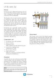
Loading Units<br />
LK 810 ThermoMat<br />
1. Heat up phase 2. Loading phase 3. End phase 4. Self-circulation<br />
with check valve<br />
8
Loading Units<br />
Loading Units for Solid Fuel Applications<br />
LK 810 ThermoMat G<br />
Compact loading unit<br />
ErP ready 2015<br />
LK 810 ThermoMat G Eco<br />
Compact loading unit with integrated low-energy circulating pump<br />
that fulfills the requirements of ErP 2015.<br />
LK 810 ThermoMat W<br />
Compact loading unit<br />
ErP ready 2015<br />
LK 810 ThermoMat W Eco<br />
Compact loading unit with integrated low-energy circulating pump<br />
that fulfills the requirements of ErP 2015.<br />
ErP ready 2015<br />
LK 811 ThermoMat E Eco<br />
Compact loading unit with low-energy circulating pump that fulfills the<br />
requirements of ErP 2015 and integrated mixing valve to be equipped<br />
with electronic temperature control.<br />
ErP ready 2015<br />
LK 815 ThermoKit T Eco<br />
Loading group with low-energy circulating pump that<br />
fulfills the requirements of ErP 2015.<br />
ErP ready 2015<br />
LK 816 ThermoKit E Eco<br />
Electronic loading group with low-energy circulating pump that<br />
fulfills the requirements of ErP 2015.<br />
9
Loading Units | LK 810 ThermoMat G<br />
LK 810 ThermoMat G<br />
Technical Data<br />
Voltage<br />
Power consumption<br />
230 VAC 50 Hz<br />
65-95 W depending on pump<br />
speed<br />
Max. boiler capacity 90 kW at 30°C ΔT<br />
Return temperatures 55°C, 60°C, 65°C or 70°C<br />
Working temperature Min. +5°C/Max. +110°C<br />
Ambient temperature Min. +5°C/Max. +60°C<br />
Max. working pressure 1.0 MPa (10 bar)<br />
Max. flow<br />
2800 l/h<br />
Media Water - Glycol mixture max. 50%<br />
Thread standard Rp - female thread<br />
Circulating pump Grundfos UPSO 65<br />
Low Energy<br />
Material, valve body Brass EN 1982 CB752S<br />
Material, insulation Expanded Polypropylene EPP<br />
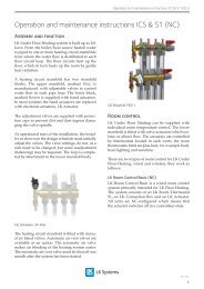
LK 810 ThermoMat G is a loading unit for heating applications<br />
with solid fuel boilers and storage tanks. The loading<br />
unit is intended to ensure a high return temperature as<br />
well as an optimal temperature stratification in the storage<br />
tank, thus increasing the efficiency of the system. Tarring<br />
and condensation are prevented which prolongs boiler life.<br />
The LK 810 ThermoMat G is a compact design with an<br />
integrated circulating pump and a thermic loading valve<br />
that regulates on two ports. The loading unit has three ball<br />
valves to simplify installation and maintenance, three thermometers<br />
that allow for simple control of the loading process and<br />
an insulation to minimize heat loss. The loading unit is available<br />
in two versions - with or without check valve. With a check<br />
valve the functions described under phase 4 will be obtained.<br />
LK 810 ThermoMat G is installed in the return circuit between<br />
the solid fuel boiler and the storage tank. The unit should<br />
be mounted upright with the drive-shaft of the circulating<br />
pump in a horizontal position. The loading unit is reversible<br />
and can easily be adapted for mounting to the right or left<br />
of the boiler.<br />
The loading unit normally requires no maintenance. The<br />
installation should be checked regularly. Thanks to the three<br />
ball valves any part can be changed without draining the<br />
system in case of servicing.<br />
The function of the loading unit during the different<br />
phases of heating:<br />
1. Heat up phase<br />
The water circulates between boiler<br />
and loading unit while the temperature<br />
of the boiler is rising.<br />
2. Loading phase<br />
The thermostatic element starts to<br />
open and allows return water from<br />
the storage tank to be mixed with<br />
supply water before it returns to the<br />
boiler. The return temperature to the<br />
boiler is kept constant.<br />
3. End phase<br />
The thermostatic element is fully<br />
open and the bypass is closed.<br />
This results in an optimal transfer<br />
of heat from the boiler and the<br />
storage tank is filled with supply<br />
water.<br />
4.Self-circulation with check valve<br />
Self-circulation will be obtained as<br />
soon as the fire has gone out and the<br />
circulating pump has stopped. The<br />
remaining hot water is loaded to<br />
the storage tank. In case of power<br />
failure or pump breakdown the<br />
check valve automatically opens<br />
to allow self-circulation. The<br />
check valve also stops recirculation<br />
from storage tank to boiler.<br />
10
Loading Units | LK 810 ThermoMat G<br />
Pump Characteristics<br />
Boiler Capacity Diagram<br />
70<br />
100<br />
60<br />
50<br />
III<br />
II<br />
80<br />
∆p (kPa)<br />
40<br />
30<br />
I<br />
Capacity (kW)<br />
60<br />
40<br />
20<br />
10<br />
20<br />
0<br />
0.0 0.5 1.0 1.5 2.0 2.5 3.0<br />
Flow (m³/h)<br />
0<br />
0.0 0.5 1.0 1.5 2.0 2.5 3.0<br />
Flow (m³/h)<br />
With Check Valve<br />
Without Check Valve<br />
LK 810 G - Female thread<br />
E<br />
C<br />
D<br />
B<br />
A<br />
F<br />
Article<br />
number<br />
Type<br />
Return<br />
temperature<br />
Dim. A mm B mm C mm D mm E mm F mm Weight kg<br />
180005 without check valve 55°C F 1” 209 201 203 263 88 130 3.9<br />
180007 without check valve 55°C F 1¼” 211 205 205 265 90 130 3.9<br />
180011 without check valve 60°C F 1” 209 201 203 263 88 130 3.9<br />
180013 without check valve 60°C F 1¼” 211 205 205 265 90 130 3.9<br />
180017 without check valve 65°C F 1” 209 201 203 263 88 130 3.9<br />
180019 without check valve 65°C F 1¼” 211 205 205 265 90 130 3.9<br />
180596 without check valve 70°C F 1” 209 201 203 263 88 130 3.9<br />
180598 without check valve 70°C F 1¼” 211 205 205 265 90 130 3.9<br />
180006 with check valve 55°C F 1” 209 201 203 263 88 130 3.9<br />
180008 with check valve 55°C F 1¼” 211 205 205 265 90 130 3.9<br />
180012 with check valve 60°C F 1” 209 201 203 263 88 130 3.9<br />
180014 with check valve 60°C F 1¼” 211 205 205 265 90 130 3.9<br />
180018 with check valve 65°C F 1” 209 201 203 263 88 130 3.9<br />
180020 with check valve 65°C F 1¼” 211 205 205 265 90 130 3.9<br />
180597 with check valve 70°C F 1” 209 201 203 263 88 130 3.9<br />
180599 with check valve 70°C F 1¼” 211 205 205 265 90 130 3.9<br />
11
Loading Units | LK 810 ThermoMat G<br />
LK 810 G - Compression fitting<br />
E<br />
C<br />
D<br />
Article<br />
number<br />
Type<br />
Return<br />
temperature<br />
B<br />
A<br />
F<br />
Dim. A mm B mm C mm D mm E mm F mm Weight kg<br />
180009 without check valve 55°C 28 mm 214 211 208 268 93 130 3.9<br />
180015 without check valve 60°C 28 mm 214 211 208 268 93 130 3.9<br />
180021 without check valve 65°C 28 mm 214 211 208 268 93 130 3.9<br />
180600 without check valve 70°C 28 mm 214 211 208 268 93 130 3.9<br />
180010 with check valve 55°C 28 mm 214 211 208 268 93 130 3.9<br />
180016 with check valve 60°C 28 mm 214 211 208 268 93 130 3.9<br />
180022 with check valve 65°C 28 mm 214 211 208 268 93 130 3.9<br />
180601 with check valve 70°C 28 mm 214 211 208 268 93 130 3.9<br />
Spare parts and Accessories<br />
9<br />
10<br />
Article<br />
number<br />
Article<br />
Position<br />
number<br />
1<br />
2<br />
5<br />
187014 Pump motor Grundfos UPSO 65 1<br />
187015 LK 810 Thermostatic element 55°C 2<br />
187016 LK 810 Thermostatic element 60°C 2<br />
187023 LK 810 Thermostatic element 65°C 2<br />
3<br />
187024 LK 810 Thermostatic element 70°C 2<br />
187017 Ball valve F 1” 3<br />
4<br />
187018 Ball valve F 1¼” 4<br />
187019 Ball valve 28 mm 5<br />
013025 Gasket EPDM 1½” -<br />
Ø44 x Ø27 x 2 mm<br />
6<br />
12<br />
11<br />
6<br />
180352 Thermometer 120°C -<br />
7<br />
Ø51 x Ø7 mm, L60 mm<br />
187020 EPP insulation LK 810 8<br />
8<br />
016168 Element housing 9<br />
014069 Spring 10<br />
7<br />
187021 Check valve LK 810 11<br />
187022 Plug LK 810 12<br />
12
Loading Units | LK 810 ThermoMat G Eco<br />
LK 810 ThermoMat G Eco<br />
ErP ready 2015<br />
Technical Data<br />
Voltage<br />
Power consumption<br />
230 VAC 50 Hz<br />
5-45 W depending on pump<br />
speed<br />
Max. boiler capacity 75 kW at 30°C ΔT<br />
Return temperatures 55°C, 60°C, 65°C or 70°C<br />
Working temperature Min. +5°C/Max. +110°C<br />
Ambient temperature Min. +5°C/Max. +60°C<br />
Max. working pressure 1.0 MPa (10 bar)<br />
Max. flow<br />
2300 l/h<br />
Media Water - Glycol mixture max. 50%<br />
Thread standard Rp - female thread<br />
Circulating pump Grundfos Alpha 2L 60<br />
Material, valve body Brass EN 1982 CB752S<br />
Material, insulation Expanded Polypropylene EPP<br />
LK 810 ThermoMat G Eco is a loading unit for heating<br />
applications with solid fuel boilers and storage tanks. The<br />
loading unit is intended to ensure a high return temperature as<br />
well as an optimal temperature stratification in the storage tank,<br />
thus increasing the efficiency of the system. Tarring and<br />
condensation are prevented which prolongs boiler life.<br />
The LK 810 ThermoMat G Eco is a compact design with<br />
an integrated low-energy circulating pump, that fulfills<br />
the requirements of ErP 2015, and a thermic loading valve<br />
that regulates on two ports. The loading unit has three ball<br />
valves to simplify installation and maintenance, three thermometers<br />
that allow for simple control of the loading process<br />
and an insulation to minimize heat loss. The loading unit is<br />
available in two versions - with or without check valve. With<br />
a check valve the functions described under phase 4 will be<br />
obtained.<br />
LK 810 ThermoMat G Eco is installed in the return circuit<br />
between the solid fuel boiler and the storage tank. The unit<br />
should be mounted upright with the drive-shaft of the<br />
circulating pump in a horizontal position. The loading unit<br />
is reversible and can easily be adapted for mounting to the<br />
right or left of the boiler.<br />
The loading unit normally requires no maintenance. The<br />
installation should be checked regularly. Thanks to the three<br />
ball valves any part can be changed without draining the<br />
system in case of servicing.<br />
The function of the loading unit during the different<br />
phases of heating:<br />
1. Heat up phase<br />
The water circulates between boiler<br />
and loading unit while the temperature<br />
of the boiler is rising.<br />
2. Loading phase<br />
The thermostatic element starts to<br />
open and allows return water from<br />
the storage tank to be mixed with<br />
supply water before it returns to the<br />
boiler. The return temperature to the<br />
boiler is kept constant.<br />
3. End phase<br />
The thermostatic element is fully<br />
open and the bypass is closed.<br />
This results in an optimal transfer<br />
of heat from the boiler and the<br />
storage tank is filled with supply<br />
water.<br />
4.Self-circulation with check valve<br />
Self-circulation will be obtained as<br />
soon as the fire has gone out and the<br />
circulating pump has stopped. The<br />
remaining hot water is loaded to<br />
the storage tank. In case of power<br />
failure or pump breakdown the<br />
check valve automatically opens<br />
to allow self-circulation. The check<br />
valve also stops recirculation from<br />
storage tank to boiler.<br />
13
Loading Units | LK 810 ThermoMat G Eco<br />
70<br />
Pump Characteristics<br />
100<br />
Boiler Capacity Diagram<br />
60<br />
50<br />
III<br />
80<br />
∆p (kPa)<br />
40<br />
30<br />
II<br />
Capacity (kW)<br />
60<br />
40<br />
20<br />
10<br />
I<br />
20<br />
0<br />
0.0 0.5 1.0 1.5 2.0 2.5 3.0<br />
Flow (m³/h)<br />
With Check Valve<br />
0<br />
0.0 0.5 1.0 1.5 2.0 2.5 3.0<br />
Flow (m³/h)<br />
Without Check Valve<br />
LK 810 G Eco- Female thread<br />
E<br />
C<br />
D<br />
A<br />
B<br />
F<br />
Article<br />
number<br />
Type<br />
Return<br />
temperature<br />
Dim. A mm B mm C mm D mm E mm F mm Weight kg<br />
181048 without check valve 55°C F 1” 235 201 203 263 88 130 3.5<br />
181050 without check valve 55°C F 1¼” 237 205 205 265 90 130 3.6<br />
181054 without check valve 60°C F 1” 235 201 203 263 88 130 3.5<br />
181056 without check valve 60°C F 1¼” 237 205 205 265 90 130 3.6<br />
181060 without check valve 65°C F 1” 235 201 203 263 88 130 3.5<br />
181062 without check valve 65°C F 1¼” 237 205 205 265 90 130 3.6<br />
181066 without check valve 70°C F 1” 235 201 203 263 88 130 3.5<br />
181068 without check valve 70°C F 1¼” 237 205 205 265 90 130 3.6<br />
181049 with check valve 55°C F 1” 235 201 203 263 88 130 3.5<br />
181051 with check valve 55°C F 1¼” 237 205 205 265 90 130 3.6<br />
181055 with check valve 60°C F 1” 235 201 203 263 88 130 3.5<br />
181057 with check valve 60°C F 1¼” 237 205 205 265 90 130 3.6<br />
181061 with check valve 65°C F 1” 235 201 203 263 88 130 3.5<br />
181063 with check valve 65°C F 1¼” 237 205 205 265 90 130 3.6<br />
181067 with check valve 70°C F 1” 235 201 203 263 88 130 3.5<br />
181069 with check valve 70°C F 1¼” 237 205 205 265 90 130 3.6<br />
14
Loading Units | LK 810 ThermoMat G Eco<br />
LK 810 G Eco - Compression fitting<br />
E<br />
C<br />
D<br />
A<br />
B<br />
F<br />
Article<br />
number<br />
Type<br />
Return<br />
temperature<br />
Dim. A mm B mm C mm D mm E mm F mm Weight kg<br />
181052 without check valve 55°C 28 mm 240 211 208 268 93 130 3.6<br />
181058 without check valve 60°C 28 mm 240 211 208 268 93 130 3.6<br />
181064 without check valve 65°C 28 mm 240 211 208 268 93 130 3.6<br />
181070 without check valve 70°C 28 mm 240 211 208 268 93 130 3.6<br />
181053 with check valve 55°C 28 mm 240 211 208 268 93 130 3.6<br />
181059 with check valve 60°C 28 mm 240 211 208 268 93 130 3.6<br />
181065 with check valve 65°C 28 mm 240 211 208 268 93 130 3.6<br />
181071 with check valve 70°C 28 mm 240 211 208 268 93 130 3.6<br />
Spare parts and Accessories<br />
9<br />
1<br />
10<br />
2<br />
12<br />
11<br />
8<br />
6<br />
7<br />
5<br />
3<br />
4<br />
Article<br />
number<br />
Article<br />
187040 Pump motor Grundfos Alpha 2L60 1<br />
187015 LK 810 Thermostatic element 55°C 2<br />
187016 LK 810 Thermostatic element 60°C 2<br />
187023 LK 810 Thermostatic element 65°C 2<br />
187024 LK 810 Thermostatic element 70°C 2<br />
187017 Ball valve F 1” 3<br />
187018 Ball valve F 1¼” 4<br />
187019 Ball valve 28 mm 5<br />
013025 Gasket EPDM 1½” -<br />
6<br />
Ø44 x Ø27 x 2 mm<br />
180352 Thermometer 120°C -<br />
7<br />
Ø51 x Ø7 mm, L60 mm<br />
187020 EPP insulation LK 810 8<br />
016168 Element housing 9<br />
014069 Spring 10<br />
187021 Check valve LK 810 11<br />
187022 Plug LK 810 12<br />
Position<br />
number<br />
15
Loading Units | LK 810 ThermoMat W<br />
LK 810 ThermoMat W<br />
Technical Data<br />
Voltage<br />
Power consumption<br />
230 VAC 50 Hz<br />
62-132 W depending on<br />
pump speed<br />
Max. boiler capacity 95 kW at 30°C ΔT<br />
Return temperatures 55°C, 60°C, 65°C or 70°C<br />
Working temperature Min. +5°C/Max. +110°C<br />
Ambient temperature Min. +5°C/Max. +60°C<br />
Max. working pressure 1.0 MPa (10 bar)<br />
Max. flow<br />
2900 l/h<br />
Media Water - Glycol mixture max. 50%<br />
Thread standard Rp - female thread<br />
Circulating pump Wilo Star RS/7-3<br />
Material, valve body Brass EN 1982 CB752S<br />
Material, insulation Expanded Polypropylene EPP<br />
LK 810 ThermoMat W is a loading unit for heating applications<br />
with solid fuel boilers and storage tanks. The loading unit<br />
is intended to ensure a high return temperature as well as<br />
an optimal temperature stratification in the storage tank,<br />
thus increasing the efficiency of the system. Tarring and<br />
condensation are prevented which prolongs boiler life.<br />
The LK 810 ThermoMat W is a compact design with an<br />
integrated circulating pump and a thermic loading valve<br />
that regulates on two ports. The loading unit has three ball<br />
valves to simplify installation and maintenance, three thermometers<br />
that allow for simple control of the loading process<br />
and an insulation to minimize heat loss. The loading unit is<br />
available in two versions - with or without check valve. With<br />
a check valve the functions described under phase 4 will be<br />
obtained.<br />
LK 810 ThermoMat W is installed in the return circuit<br />
between the solid fuel boiler and the storage tank. The<br />
unit should be mounted upright with the drive-shaft of the<br />
circulating pump in a horizontal position. The loading unit<br />
is reversible and can easily be adapted for mounting to the<br />
right or left of the boiler.<br />
The loading unit normally requires no maintenance. The<br />
installation should be checked regularly. Thanks to the three<br />
ball valves any part can be changed without draining the<br />
system in case of servicing.<br />
The function of the loading unit during the different<br />
phases of heating:<br />
1. Heat up phase<br />
The water circulates between boiler<br />
and loading unit while the temperature<br />
of the boiler is rising.<br />
2. Loading phase<br />
The thermostatic element starts to<br />
open and allows return water from<br />
the storage tank to be mixed with<br />
supply water before it returns to the<br />
boiler. The return temperature to the<br />
boiler is kept constant.<br />
3. End phase<br />
The thermostatic element is fully<br />
open and the bypass is closed.<br />
This results in an optimal transfer<br />
of heat from the boiler and the<br />
storage tank is filled with supply<br />
water.<br />
4.Self-circulation with check valve<br />
Self-circulation will be obtained as<br />
soon as the fire has gone out and the<br />
circulating pump has stopped. The<br />
remaining hot water is loaded to<br />
the storage tank. In case of power<br />
failure or pump breakdown the<br />
check valve automatically opens<br />
to allow self-circulation. The<br />
check valve also stops recirculation<br />
from storage tank to boiler.<br />
16
Loading Units | LK 810 ThermoMat W<br />
Pump Characteristics<br />
Boiler Capacity Diagram<br />
70<br />
100<br />
60<br />
50<br />
III<br />
II<br />
80<br />
∆p (kPa)<br />
40<br />
30<br />
I<br />
Capacity (kW)<br />
60<br />
40<br />
20<br />
10<br />
20<br />
0<br />
0.0 0.5 1.0 1.5 2.0 2.5 3.0<br />
Flow (m³/h)<br />
With Check Valve<br />
0<br />
0.0 0.5 1.0 1.5 2.0 2.5 3.0<br />
Flow (m³/h)<br />
Without Check Valve<br />
LK 810 W - Female thread<br />
E<br />
C<br />
D<br />
A<br />
B<br />
F<br />
Article<br />
number<br />
Type<br />
Return<br />
temperature<br />
Dim. A mm B mm C mm D mm E mm F mm Weight<br />
kg<br />
180023 without check valve 55°C F 1” 227 201 203 263 88 130 4.1<br />
180025 without check valve 55°C F 1¼” 229 205 205 265 90 130 4.1<br />
180029 without check valve 60°C F 1” 227 201 203 263 88 130 4.1<br />
180031 without check valve 60°C F 1¼” 229 205 205 265 90 130 4.1<br />
180035 without check valve 65°C F 1” 227 201 203 263 88 130 4.1<br />
180037 without check valve 65°C F 1¼” 229 205 205 265 90 130 4.1<br />
181101 without check valve 70°C F 1” 227 201 203 263 88 130 4.1<br />
181103 without check valve 70°C F 1¼” 229 205 205 265 90 130 4.1<br />
180024 with check valve 55°C F 1” 227 201 203 263 88 130 4.1<br />
180026 with check valve 55°C F 1¼” 229 205 205 265 90 130 4.1<br />
180030 with check valve 60°C F 1” 227 201 203 263 88 130 4.1<br />
180032 with check valve 60°C F 1¼” 229 205 205 265 90 130 4.1<br />
180036 with check valve 65°C F 1” 227 201 203 263 88 130 4.1<br />
180038 with check valve 65°C F 1¼” 229 205 205 265 90 130 4.1<br />
181102 with check valve 70°C F 1” 227 201 203 263 88 130 4.1<br />
181104 with check valve 70°C F 1¼” 229 205 205 265 90 130 4.1<br />
17
Loading Units | LK 810 ThermoMat W<br />
LK 810 W - Compression fitting<br />
E<br />
C<br />
D<br />
A<br />
B<br />
F<br />
Article<br />
number<br />
Type<br />
Return<br />
temperature<br />
Dim. A mm B mm C mm D mm E mm F mm Weight<br />
kg<br />
180027 without check valve 55°C 28 mm 232 211 208 268 93 130 4.1<br />
180033 without check valve 60°C 28 mm 232 211 208 268 93 130 4.1<br />
180039 without check valve 65°C 28 mm 232 211 208 268 93 130 4.1<br />
181105 without check valve 70°C 28 mm 232 211 208 268 93 130 4.1<br />
180028 with check valve 55°C 28 mm 232 211 208 268 93 130 4.1<br />
180034 with check valve 60°C 28 mm 232 211 208 268 93 130 4.1<br />
180040 with check valve 65°C 28 mm 232 211 208 268 93 130 4.1<br />
181106 with check valve 70°C 28 mm 232 211 208 268 93 130 4.1<br />
Spare parts and Accessories<br />
9<br />
10<br />
Article<br />
number<br />
Article<br />
Position<br />
number<br />
1<br />
13<br />
2<br />
5<br />
3<br />
187085 Pump motor Wilo RS/7-3 1<br />
187015 LK 810 Thermostatic element 55°C 2<br />
187016 LK 810 Thermostatic element 60°C 2<br />
187023 LK 810 Thermostatic element 65°C 2<br />
187024 LK 810 Thermostatic element 70°C 2<br />
4<br />
187017 Ball valve F 1” 3<br />
187018 Ball valve F 1¼” 4<br />
187019 Ball valve 28 mm 5<br />
013025 Gasket EPDM 1½” -<br />
Ø44 x Ø27 x 2 mm<br />
6<br />
12<br />
11<br />
6<br />
180352 Thermometer 120°C -<br />
Ø51 x Ø7 mm, L60 mm<br />
7<br />
187020 EPP insulation LK 810 8<br />
016168 Element housing 9<br />
8<br />
014069 Spring 10<br />
187021 Check valve LK 810 11<br />
7<br />
187022 Plug LK 810 12<br />
026136 Gasket 13<br />
18
Loading Units | LK 810 ThermoMat W Eco<br />
LK 810 ThermoMat W Eco<br />
ErP ready 2015<br />
Technical Data<br />
Voltage<br />
Power consumption<br />
230 VAC 50 Hz<br />
3-45 W depending on pump<br />
speed<br />
Max. boiler capacity 85 kW at 30°C ΔT<br />
Return temperatures 55°C, 60°C, 65°C or 70°C<br />
Working temperature Min. +5°C/Max. +110°C<br />
Ambient temperature Min. +5°C/Max. +60°C<br />
Max. working pressure 0,6 MPa (6 bar)<br />
Max. flow<br />
2500 l/h<br />
Media Water - Glycol mixture max. 50%<br />
Thread standard Rp - female thread<br />
Circulating pump Wilo Yonos PARA */6 RKC<br />
Material, valve body Brass EN 1982 CB752S<br />
Material, insulation Expanded Polypropylene EPP<br />
LK 810 ThermoMat W Eco is a loading unit for heating<br />
applications with solid fuel boilers and storage tanks. The<br />
loading unit is intended to ensure a high return temperature as<br />
well as an optimal temperature stratification in the storage tank,<br />
thus increasing the efficiency of the system. Tarring and<br />
condensation are prevented which prolongs boiler life.<br />
The LK 810 ThermoMat W Eco is a compact design with<br />
an integrated low-energy circulating pump, that fulfills<br />
the requirements of ErP 2015, and a thermic loading valve<br />
that regulates on two ports. The loading unit has three ball<br />
valves to simplify installation and maintenance, three thermometers<br />
that allow for simple control of the loading process<br />
and an insulation to minimize heat loss. The loading unit is<br />
available in two versions - with or without check valve. With<br />
a check valve the functions described under phase 4 will be<br />
obtained.<br />
LK 810 ThermoMat W Eco is installed in the return circuit<br />
between the solid fuel boiler and the storage tank. The unit<br />
should be mounted upright with the drive-shaft of the<br />
circulating pump in a horizontal position. The loading unit<br />
is reversible and can easily be adapted for mounting to the<br />
right or left of the boiler.<br />
The loading unit normally requires no maintenance. The<br />
installation should be checked regularly. Thanks to the three<br />
ball valves any part can be changed without draining the<br />
system in case of servicing.<br />
The function of the loading unit during the different<br />
phases of heating:<br />
1. Heat up phase<br />
The water circulates between boiler<br />
and loading unit while the temperature<br />
of the boiler is rising.<br />
2. Loading phase<br />
The thermostatic element starts to<br />
open and allows return water from<br />
the storage tank to be mixed with<br />
supply water before it returns to the<br />
boiler. The return temperature to the<br />
boiler is kept constant.<br />
3. End phase<br />
The thermostatic element is fully<br />
open and the bypass is closed.<br />
This results in an optimal transfer<br />
of heat from the boiler and the<br />
storage tank is filled with supply<br />
water.<br />
4.Self-circulation with check valve<br />
Self-circulation will be obtained as<br />
soon as the fire has gone out and the<br />
circulating pump has stopped. The<br />
remaining hot water is loaded to<br />
the storage tank. In case of power<br />
failure or pump breakdown the<br />
check valve automatically opens<br />
to allow self-circulation. The check<br />
valve also stops recirculation from<br />
storage tank to boiler.<br />
19
Loading Units | LK 810 ThermoMat W Eco<br />
70<br />
Pump Characteristics<br />
100<br />
Boiler Capacity Diagram<br />
60<br />
50<br />
III<br />
80<br />
∆p (kPa)<br />
40<br />
30<br />
II<br />
Capacity (kW)<br />
60<br />
40<br />
20<br />
10<br />
I<br />
20<br />
0<br />
0.0 0.5 1.0 1.5 2.0 2.5 3.0<br />
Flow (m³/h)<br />
With Check Valve<br />
0<br />
0.0 0.5 1.0 1.5 2.0 2.5 3.0<br />
Flow (m³/h)<br />
Without Check Valve<br />
LK 810 W Eco - Female thread<br />
E<br />
C<br />
D<br />
B<br />
A<br />
F<br />
Article<br />
number<br />
Type<br />
Return<br />
temperature<br />
Dim. A mm B mm C mm D mm E mm F mm Weight kg<br />
181048 without check valve 55°C F 1” 216 201 203 263 88 130 4.5<br />
181050 without check valve 55°C F 1¼” 218 205 205 265 90 130 4.5<br />
181054 without check valve 60°C F 1” 216 201 203 263 88 130 4.5<br />
181056 without check valve 60°C F 1¼” 218 205 205 265 90 130 4.5<br />
181060 without check valve 65°C F 1” 216 201 203 263 88 130 4.5<br />
181062 without check valve 65°C F 1¼” 218 205 205 265 90 130 4.5<br />
181066 without check valve 70°C F 1” 216 201 203 263 88 130 4.5<br />
181068 without check valve 70°C F 1¼” 218 205 205 265 90 130 4.5<br />
181049 with check valve 55°C F 1” 216 201 203 263 88 130 4.5<br />
181051 with check valve 55°C F 1¼” 218 205 205 265 90 130 4.5<br />
181055 with check valve 60°C F 1” 216 201 203 263 88 130 4.5<br />
181057 with check valve 60°C F 1¼” 218 205 205 265 90 130 4.5<br />
181061 with check valve 65°C F 1” 216 201 203 263 88 130 4.5<br />
181063 with check valve 65°C F 1¼” 218 205 205 265 90 130 4.5<br />
181067 with check valve 70°C F 1” 216 201 203 263 88 130 4.5<br />
181069 with check valve 70°C F 1¼” 218 205 205 265 90 130 4.5<br />
20
Loading Units | LK 810 ThermoMat W Eco<br />
LK 810 W Eco - Compression fitting<br />
E<br />
C<br />
D<br />
Article<br />
number<br />
Type<br />
Return<br />
temperature<br />
B<br />
A<br />
F<br />
Dim. A mm B mm C mm D mm E mm F mm Weight kg<br />
181052 without check valve 55°C 28 mm 221 211 208 268 93 130 4.5<br />
181058 without check valve 60°C 28 mm 221 211 208 268 93 130 4.5<br />
181064 without check valve 65°C 28 mm 221 211 208 268 93 130 4.5<br />
181070 without check valve 70°C 28 mm 221 211 208 268 93 130 4.5<br />
181053 with check valve 55°C 28 mm 221 211 208 268 93 130 4.5<br />
181059 with check valve 60°C 28 mm 221 211 208 268 93 130 4.5<br />
181065 with check valve 65°C 28 mm 221 211 208 268 93 130 4.5<br />
181071 with check valve 70°C 28 mm 221 211 208 268 93 130 4.5<br />
Spare parts and Accessories<br />
9<br />
14<br />
1<br />
10<br />
2<br />
13<br />
5<br />
3<br />
Article Article<br />
number<br />
187106 Pump motor Wilo Yonos<br />
PARA */6 RKC<br />
187015 LK 810 Thermostatic element 55°C 2<br />
Position<br />
number<br />
1<br />
187016 LK 810 Thermostatic element 60°C 2<br />
4<br />
187023 LK 810 Thermostatic element 65°C 2<br />
187024 LK 810 Thermostatic element 70°C 2<br />
187017 Ball valve F 1” 3<br />
187018 Ball valve F 1¼” 4<br />
187019 Ball valve 28 mm 5<br />
12<br />
11<br />
6<br />
013025 Gasket EPDM 1½” -<br />
Ø44 x Ø27 x 2 mm<br />
6<br />
180352 Thermometer 120°C -<br />
Ø51 x Ø7 mm, L60 mm<br />
7<br />
187020 EPP insulation LK 810 8<br />
016168 Element housing 9<br />
8<br />
014069 Spring 10<br />
7<br />
187021 Check valve LK 810 11<br />
187022 Plug LK 810 12<br />
026136 Gasket 13<br />
095220 Connector 14<br />
21
Loading Units | LK 811 ThermoMat E Eco<br />
LK 811 ThermoMat E Eco<br />
Technical Data<br />
Voltage<br />
Power consumption<br />
230 VAC 50 Hz<br />
3-45 W depending on pump<br />
speed<br />
Max. boiler capacity 85 kW at 30°C ΔT<br />
Return temperatures 5°C - 99°C with<br />
LK 100 SmartComfort CT<br />
Working temperature Min. +5°C/Max. +95°C<br />
Ambient temperature Min. +5°C/Max. +60°C<br />
Max. working pressure 0.6 MPa (6 bar)<br />
Max. flow<br />
2500 l/h<br />
Media Water - Glycol mixture max. 50%<br />
Thread standard Rp - female thread<br />
Circulating pump Wilo Yonos PARA */6 RKC<br />
Material, valve body Brass EN 1982 CB753S<br />
Material, insulation Expanded Polypropylene EPP<br />
LK 811 ThermoMat E Eco is a loading unit for heating applications<br />
with solid fuel boilers and storage tanks. The loading<br />
unit is intended to ensure a high return temperature as well<br />
as an optimal temperature stratification in the storage tank,<br />
thus increasing the efficiency of the system. Tarring and<br />
condensation are prevented which prolongs boiler life.<br />
The LK 811 ThermoMat E Eco is a compact design with an<br />
integrated low-energy circulating pump, that fulfills the<br />
requirements of ErP 2015, and a mixing valve that regulates<br />
on two ports. The loading unit has three ball valves to simplify<br />
installation and maintenance and an insulation to minimize<br />
heat loss. Three thermometers that allow for simple control of<br />
the loading process can be ordered as accessories.The loading<br />
unit is available in two versions - with or without check valve.<br />
With a check valve the functions described under phase 4<br />
will be obtained.<br />
LK 811 ThermoMat E Eco is to be equiped with an electronic<br />
temperature controller, preferably an LK 100 SmartComfort<br />
CT. Mounting kits for controllers of other brands are available<br />
- see separate page.<br />
LK 811 ThermoMat E Eco is installed in the return circuit between<br />
the solid fuel boiler and the storage tank. The unit<br />
should be mounted upright with the drive-shaft of the<br />
circulating pump in a horizontal position. The loading unit<br />
is reversible and can easily be adapted for mounting to the<br />
right or left of the boiler.<br />
The loading unit normally requires no maintenance. The<br />
installation should be checked regularly. Thanks to the three<br />
ball valves any part can be changed without draining the<br />
system in case of servicing.<br />
ErP ready 2015<br />
The function of the loading unit during the different<br />
phases of heating:<br />
1. Heat up phase<br />
The water circulates between boiler<br />
and loading unit while the temperature<br />
of the boiler is rising.<br />
2. Loading phase<br />
The mixing valve starts to open<br />
and allows return water from<br />
the storage tank to be mixed with<br />
supply water before it returns to<br />
the boiler. The return temperature<br />
to the boiler is kept constant.<br />
3. End phase<br />
The mixing valve is fully open<br />
towards the storage tank. This results<br />
in an optimal transfer of heat<br />
from the boiler and the storage tank<br />
is filled with supply water. When<br />
the boiler has cooled the electronic<br />
controller LK 100 SmartComfort CT<br />
prevents re-circulation from storage<br />
tank to boiler.<br />
4.Self-circulation with check valve<br />
Self-circulation will be obtained as<br />
soon as the fire has gone out and the<br />
circulating pump has stopped. The<br />
remaining hot water is loaded to<br />
the storage tank. In case of power<br />
failure or pump breakdown the<br />
check valve automatically opens<br />
to allow self-circulation. The check<br />
valve also stops recirculation from<br />
storage tank to boiler.<br />
22
Loading Units | LK 811 ThermoMat E Eco<br />
70<br />
Pump Characteristics<br />
100<br />
Boiler Capacity Diagram<br />
60<br />
III<br />
80<br />
50<br />
∆p (kPa)<br />
40<br />
30<br />
II<br />
Capacity (kW)<br />
60<br />
40<br />
20<br />
10<br />
I<br />
20<br />
0<br />
0.0 0.5 1.0 1.5 2.0 2.5 3.0<br />
Flow (m³/h)<br />
With Check Valve<br />
0<br />
0.0 0.5 1.0 1.5 2.0 2.5 3.0<br />
Flow (m³/h)<br />
Without Check Valve<br />
LK 811 - Female thread<br />
E<br />
C<br />
D<br />
B<br />
A<br />
F<br />
Article Type Dim. A mm B mm C mm D mm E mm F mm Weight kg<br />
number<br />
181436 with check valve F 1” 219 201 228 288 88 130 3.9<br />
181437 without check valve F 1” 219 201 228 288 88 130 3.9<br />
181438 with check valve F 1¼” 221 205 230 290 90 130 3.9<br />
181439 without check valve F 1¼” 221 205 230 290 90 130 3.9<br />
LK 811 - Compression fitting<br />
E<br />
C<br />
D<br />
A<br />
B<br />
F<br />
Article Type Dim. A mm B mm C mm D mm E mm F mm Weight kg<br />
number<br />
181440 with check valve 28 mm 224 211 233 293 93 130 3.9<br />
181441 without check valve 28 mm 224 211 233 293 93 130 3.9<br />
23
Loading Units | LK 811 ThermoMat E Eco<br />
Spare parts and Accessories<br />
2 3 4<br />
1<br />
10 9 11<br />
15<br />
5<br />
6<br />
5<br />
7<br />
12<br />
13<br />
14<br />
8<br />
Article Article<br />
number<br />
187111 Pump motor Wilo Yonos PARA<br />
*/6 RKC<br />
Position<br />
number<br />
1, 3<br />
095220 Connector 2<br />
187110 Repair kit 811 4-8<br />
187066 Sealing kit 5, 6, 8<br />
187021 Check valve LK 811 9<br />
187022 Plug LK 811 10<br />
013025 Gasket EPDM 1½” -<br />
11<br />
Ø44 x Ø27 x 2 mm<br />
187017 Ball valve F 1” 12<br />
187018 Ball valve F 1¼” 13<br />
187019 Ball valve 28 mm 14<br />
187112 EPP insulation LK 811 15<br />
058126 Thermometer 120°C -<br />
Ø51 x Ø7 mm, L75 mm<br />
16<br />
16<br />
24
Loading Units | LK 815 ThermoKit T Eco<br />
LK 815 ThermoKit T Eco<br />
Technical Data<br />
Voltage<br />
230-240 VAC 50 Hz<br />
Power consumption 10-140 W depending on pump<br />
speed<br />
Max. boiler capacity 150 kW at 20°C ΔT<br />
Return temperatures 45°C, 50°C, 55°C or 60°C<br />
Working temperature Min. +5°C/Max. +95°C<br />
Ambient temperature Min. +5°C/Max. +40°C<br />
Max. working pressure 1.0 MPa (10 bar)<br />
Max. flow<br />
6500 l/h<br />
Media Water - Glycol mixture max. 50%<br />
Thread standard Rp - female thread<br />
Circulating pump Grundfos Magna 25-80<br />
Material, valve body Brass EN 1982 CB753S<br />
Material, insulation Expanded Polypropylene EPP<br />
LK 815 ThermoKit T Eco is a loading group for heating applications<br />
with solid fuel boilers and storage tanks. The loading<br />
group is intended to ensure a high return temperature as well<br />
as an optimal temperature stratification in the storage tank,<br />
thus increasing the efficiency of the system. Tarring and<br />
condensation are prevented which prolongs boiler life.<br />
LK 815 ThermoKit T Eco consists of a low-energy circulating<br />
pump, that fulfills the requirements of ErP 2015, an<br />
LK 823 ThermoVar thermic loading valve with i nsulation, a<br />
check valve, a thermometer for reading return temperatures<br />
and three ball valves to simplify installation and maintenance.<br />
LK 815 ThermoKit T Eco is installed in the return circuit between<br />
the solid fuel boiler and the storage tank. The group<br />
should be mounted with the drive-shaft of the circulating<br />
pump in a horizontal position. The loading group is reversible<br />
and can easily be adapted for mounting to the right or left<br />
of the boiler.<br />
The loading group normally requires no maintenance. The<br />
installation should be checked regularly. Thanks to the<br />
three ball valves any part can be changed without draining<br />
the system, should the need for servicing arise.<br />
ErP ready 2015<br />
The function of the loading unit during the different<br />
phases of heating:<br />
1. Heat up phase<br />
The water circulates between boiler and loading group<br />
while the temperature of the boiler is rising.<br />
2. Loading phase<br />
The thermic valve starts to open and allows return water<br />
from the storage tank to be mixed with supply water before<br />
it returns to the boiler. The return temperature to the boiler<br />
is kept constant.<br />
3. End phase<br />
The thermostatic element is fully open. This results in an<br />
optimal transfer of heat from the boiler and the storage<br />
tank is filled with supply water.<br />
4. Self-circulation<br />
As soon as the fire has gone out and the circulating pump<br />
has stopped the remaining hot water in the boiler is loaded<br />
to the storage tank as long as the thermic valve remains<br />
open. When the boiler has cooled the thermic valve closes.<br />
The check valve prevents recirculation from storage tank<br />
to boiler.<br />
25
Loading Units | LK 815 ThermoKit T Eco<br />
∆p (kPa)<br />
90<br />
80<br />
70<br />
60<br />
50<br />
40<br />
30<br />
20<br />
10<br />
0<br />
100%<br />
70%<br />
34%<br />
Pump Characteristics<br />
0.0 1.0 2.0 3.0 4.0 5.0 6.0 7.0<br />
Flow (m³/h)<br />
Capacity (kW)<br />
Boiler Capacity Diagram<br />
200<br />
180<br />
160<br />
140<br />
120<br />
100<br />
80<br />
60<br />
40<br />
20<br />
0<br />
0.0 1.0 2.0 3.0 4.0 5.0 6.0 7.0<br />
Flow (m³/h)<br />
LK 815 - Female thread<br />
199<br />
565<br />
Article number Return temperature Dim. Weight kg<br />
181405 45°C F 1½” 8.8<br />
181406 50°C F 1½” 8.8<br />
181407 55°C F 1½” 8.8<br />
181408 60°C F 1½” 8.8<br />
26
Loading Units | LK 816 ThermoKit E Eco<br />
LK 816 ThermoKit E Eco<br />
ErP ready 2015<br />
Technical Data<br />
Voltage<br />
230-240 VAC 50 Hz<br />
Power consumption 10-140 W depending on<br />
pump speed<br />
Max. boiler capacity Dependent on circulating<br />
pump<br />
Return temperatures 5°C-99°C<br />
Working temperature Min. +5°C/Max. +95°C<br />
Ambient temperature Min. +5°C/Max. +40°C<br />
Max. working pressure 1.0 MPa (10 bar)<br />
Max. flow<br />
Dependent on circulating<br />
pump<br />
Media Water - Glycol mixture max. 50%<br />
Thread standard Rp - female thread<br />
Circulating pumps Grundfos Magna 25-80,<br />
Grundfos Magna 32-80,<br />
Material, valve body Brass EN 12165 CW617N,<br />
Material, insulation Expanded Polypropylene EPP<br />
LK 100 SmartComfort CT Electronic controller:<br />
Primary voltage, 100-240 VAC 50/60 Hz<br />
adapter<br />
Secondary voltage, 24 VDC 250 mA<br />
adapter<br />
Power consumption 3 VA<br />
Angle of rotation 90°<br />
Torque<br />
5 Nm<br />
Running time<br />
140 sec.<br />
Protection class IP 40<br />
LK 816 ThermoKit E Eco is a loading group for heating applications<br />
with solid fuel boilers and storage tanks. The loading<br />
group is intended to ensure a high return temperature as well<br />
as an optimal temperature stratification in the storage tank,<br />
thus increasing the efficiency of the system. Tarring and<br />
condensation are prevented which prolongs boiler life.<br />
LK 816 ThermoKit E Eco is a unit consisting of a lowenergy<br />
circulating pump, that fulfills the requirements<br />
of ErP 2015, an LK 840 ThermoMix mixing valve, an<br />
LK 100 SmartComfort CT controller with adjustment of the<br />
lowest return temperature 5°C-99°C and three ball valves<br />
to simplify installation and maintenance. Article number<br />
181409 is delivered with an insulation for the mixing valve.<br />
LK 816 ThermoKit E Eco is installed in the return circuit between<br />
the solid fuel boiler and the storage tank. The group<br />
should be mounted with the drive-shaft of the circulating<br />
pump in a horizontal position. The loading group is reversible<br />
and can easily be adapted for mounting to the right<br />
or left of the boiler.<br />
The loading group normally requires no maintenance. The<br />
installation should be checked regularly. Thanks to the three<br />
ball valves any part can be changed without draining the<br />
system, should the need for servicing arise.<br />
The function of the loading unit during the different<br />
phases of heating:<br />
1. Heat up phase<br />
The water circulates between boiler and loading group<br />
while the temperature of the boiler is rising.<br />
2. Loading phase<br />
The mixing valve starts to open and allows return water<br />
from the storage tank to be mixed with supply water before<br />
it returns to the boiler. The return temperature to the boiler<br />
is kept constant.<br />
3. End phase<br />
The mixing valve is fully open towards the storage tank.<br />
This results in an optimal transfer of heat from the boiler<br />
and the storage tank is filled with supply water. When the<br />
boiler has cooled the electronic controller prevents recirculation<br />
from storage tank to boiler.<br />
4. Self-circulation<br />
In case of power failure or pump breakdown the electronic<br />
controller can be manaully operated and the storage tank is<br />
loaded through self-circulation.<br />
27
Loading Units | LK 816 ThermoKit E Eco<br />
Boiler Capacity Diagram<br />
200<br />
180<br />
160<br />
140<br />
Capacity (kW)<br />
120<br />
100<br />
80<br />
60<br />
40<br />
20<br />
0<br />
0.0 1.0 2.0 3.0 4.0 5.0 6.0 7.0 8.0 9.0<br />
Flow (m³/h)<br />
LK 816 - Female thread - Grundfos Magna 25-80<br />
90<br />
80<br />
100%<br />
Pump Characteristics<br />
70<br />
165<br />
∆p (kPa)<br />
60<br />
50<br />
40<br />
70%<br />
30<br />
20<br />
Article number Return temperature Dim. Weight kg<br />
181409 5°C-99°C F 1½” 8.8<br />
544<br />
10<br />
0<br />
34%<br />
0.0 1.0 2.0 3.0 4.0 5.0 6.0 7.0 8.0<br />
Flow (m³/h)<br />
LK 816 - Female thread - Grundfos Magna 32-80<br />
Pump Characteristics<br />
90<br />
80<br />
100%<br />
186<br />
70<br />
60<br />
646<br />
∆p (kPa)<br />
50<br />
40<br />
30<br />
20<br />
10<br />
70%<br />
34%<br />
Article number Return temperature Dim. Weight kg<br />
181410 5°C-99°C F 2” 12.4<br />
0<br />
0.0 1.0 2.0 3.0 4.0 5.0 6.0 7.0 8.0 9.0<br />
Flow (m³/h)<br />
28
Thermic Valves and Check Valves<br />
Thermic Valves and Check Valves<br />
LK 820 ThermoVar<br />
3-way thermic loading valve made of brass.<br />
LK 821 ThermoVar<br />
3-way thermic zone valve made of brass.<br />
LK 823 ThermoVar<br />
3-way thermic loading valve made of brass.<br />
LK 825 ThermoVar<br />
3-way thermic loading valve made of cast iron.<br />
LK 822 ThermoBac<br />
3-way check valve made of brass.<br />
LK 826 ThermoBac<br />
3-way check valve made of cast iron.<br />
LK Insulation<br />
Insulation for ThermoVar, ThermoBac and ThermoMix.<br />
29
Thermic Valves and Check Valves | LK 820 ThermoVar<br />
LK 820 ThermoVar<br />
Technical Data<br />
Opening temperatures<br />
45°C, 55°C, 61°C, 66°C,<br />
72°C or 80°C<br />
Working temperature, 45°C - 55°C Min. +5°C/Max. +95°C<br />
Working temperature, 61°C - 80°C Min. +5°C/Max. +110°C<br />
Ambient temperature<br />
Min. +5°C/Max. +60°C<br />
Max. working pressure 1.0 MPa (10 bar)<br />
Max. pressure difference 50 kPa<br />
Media<br />
Water - Glycol<br />
mixture max. 50%<br />
Thread standard<br />
Rp - female thread<br />
G - male thread<br />
Material, valve body/cover Brass EN 12165<br />
CW617N<br />
Material, O-ring<br />
EPDM<br />
Position I<br />
As soon as the boiler temperature has reached the selected<br />
opening temperature, the thermic valve allows hot water<br />
to load to the storage tank. Return water from the storage<br />
tank is mixed with supply water before it circulates back<br />
into the boiler. The loading temperature is at least the<br />
selected opening temperature.<br />
A balancing valve should be installed in the circuit between<br />
boiler and loading valve.<br />
The installation should be equipped with an LK 822 ThermoBac<br />
check valve to prevent self-circulation from storage tank to<br />
boiler after the fire has gone out. In case of power failure or<br />
pump breakdown the check valve automatically opens for selfcirculation.<br />
The circulating pump should be controlled by a thermostat<br />
that measures the boiler’s water or flue gas temperature.<br />
LK 820 ThermoVar is a 3-way thermic loading valve for solid<br />
fuel/storage tank installations. The valve is intended to ensure<br />
both an optimal temperature stratification in the storage<br />
tank and a high return temperature to the boiler, thus incresasing<br />
the efficiency of the system. Tarring and condensation<br />
are prevented which prolongs boiler life.<br />
LK 820 can be equipped with an insulation - see under<br />
Accessories. For more information please see the product<br />
sheet for insulations - page 47.<br />
The valve can be mounted at any angle. LK 820 ThermoVar<br />
can easily be adapted for right- or left-hand mounting.<br />
The valve can be installed in three different positions.<br />
In the standard version the valve is intended for installation<br />
in position II. It can easily be adapted for installation<br />
in position I. For delivery of valves intended for installation<br />
in position III, please contact our Sales Department.<br />
Position II<br />
As soon as the boiler temperature has reached the selected<br />
opening temperature, the thermic valve allows return<br />
water from the storage tank to mix with supply water<br />
before it circulates back into the boiler. The return temperature<br />
is at least the selected opening temperature.<br />
A balancing valve should be installed in the circuit between<br />
boiler and loading valve.<br />
The circulating pump should be controlled by a thermostat<br />
that measures the boiler’s water or flue gas temperature.<br />
Position III<br />
As soon as the boiler temperature has reached the selected<br />
opening temperature, the thermic valve allows return water<br />
from the storage tank to mix with supply water before it<br />
circulates back into the boiler. The return temperature is at<br />
least the selected opening temperature.<br />
A balancing valve should be installed in the circuit between<br />
boiler and loading valve.<br />
The installation should be equipped with an LK 822 ThermoBac<br />
check valve to prevent self-circulation from the storage tank to<br />
the boiler after the fire has gone out. In case of power failure or<br />
pump breakdown the check valve opens automatically for selfcirculation.<br />
The circulating pump should be controlled by a thermostat<br />
that measures the boiler’s water or flue gas temperature.<br />
30
Thermic Valves and Check Valves | LK 820 ThermoVar<br />
Position I<br />
Position II<br />
Position III<br />
Capacity Diagram<br />
Kvs (m³/h)<br />
12<br />
10.0 9.0<br />
6.0<br />
4.0<br />
Flow (m³/h)<br />
1.0<br />
0.1<br />
0.1 1.0 10.0 100.0<br />
Pressure drop (kPa)<br />
LK 820 - Female thread<br />
B<br />
C<br />
E<br />
D<br />
A<br />
Article number Opening temperature Dim. Kvs m³/h A mm B mm C mm D mm E mm Weight kg<br />
180491 45°C F ½” 4.0 80 40 66 21 35 0.7<br />
180492 45°C F ¾” 6.0 80 40 66 21 35 0.7<br />
180493 45°C F 1” 9.0 82 41 67 21 35 0.7<br />
180494 45°C F 1¼” 12 84 42 68 24 39 0.8<br />
180499 55°C F ½” 4.0 80 40 66 21 35 0.7<br />
180500 55°C F ¾” 6.0 80 40 66 21 35 0.7<br />
180501 55°C F 1” 9.0 82 41 67 21 35 0.7<br />
180502 55°C F 1¼” 12 84 42 68 24 39 0.8<br />
180507 61°C F ½” 4.0 80 40 66 21 35 0.7<br />
180508 61°C F ¾” 6.0 80 40 66 21 35 0.7<br />
180509 61°C F 1” 9.0 82 41 67 21 35 0.7<br />
180510 61°C F 1¼” 12 84 42 68 24 39 0.8<br />
31
Thermic Valves and Check Valves | LK 820 ThermoVar<br />
LK 820 - Female thread<br />
Article number Opening temperature Dim. Kvs m³/h A mm B mm C mm D mm E mm Weight kg<br />
180515 66°C F ½” 4.0 80 40 66 21 35 0.7<br />
180516 66°C F ¾” 6.0 80 40 66 21 35 0.7<br />
180517 66°C F 1” 9.0 82 41 67 21 35 0.7<br />
180518 66°C F 1¼” 12 84 42 68 24 39 0.8<br />
180523 72°C F ½” 4.0 80 40 66 21 35 0.7<br />
180524 72°C F ¾” 6.0 80 40 66 21 35 0.7<br />
180525 72°C F 1” 9.0 82 41 67 21 35 0.7<br />
180526 72°C F 1¼” 12 84 42 68 24 39 0.8<br />
180531 80°C F ½” 4.0 80 40 66 21 35 0.7<br />
180532 80°C F ¾” 6.0 80 40 66 21 35 0.7<br />
180533 80°C F 1” 9.0 82 41 67 21 35 0.7<br />
180534 80°C F 1¼” 12 84 42 68 24 39 0.8<br />
LK 820 - Male thread<br />
B<br />
C<br />
E<br />
D<br />
A<br />
Article number Opening temperature Dim. Kvs m³/h A mm B mm C mm D mm E mm Weight kg<br />
180495 45°C M ¾” 4.0 80 40 66 21 35 0.7<br />
180496 45°C M 1” 6.0 80 40 66 21 35 0.7<br />
180497 45°C M 1¼” 9.0 84 42 68 21 35 0.7<br />
180498 45°C M 1½” 12 84 42 68 24 39 0.8<br />
180503 55°C M ¾” 4.0 80 40 66 21 35 0.7<br />
180504 55°C M 1” 6.0 80 40 66 21 35 0.7<br />
180505 55°C M 1¼” 9.0 84 42 68 21 35 0.7<br />
180506 55°C M 1½” 12 84 42 68 24 39 0.8<br />
180511 61°C M ¾” 4.0 80 40 66 21 35 0.7<br />
180512 61°C M 1” 6.0 80 40 66 21 35 0.7<br />
180513 61°C M 1¼” 9.0 84 42 68 21 35 0.7<br />
180514 61°C M 1½” 12 84 42 68 24 39 0.8<br />
180519 66°C M ¾” 4.0 80 40 66 21 35 0.7<br />
180520 66°C M 1” 6.0 80 40 66 21 35 0.7<br />
180521 66°C M 1¼” 9.0 84 42 68 21 35 0.7<br />
180522 66°C M 1½” 12 84 42 68 24 39 0.8<br />
180527 72°C M ¾” 4.0 80 40 66 21 35 0.7<br />
180528 72°C M 1” 6.0 80 40 66 21 35 0.7<br />
180529 72°C M 1¼” 9.0 84 42 68 21 35 0.7<br />
180530 72°C M 1½” 12 84 42 68 24 39 0.8<br />
180535 80°C M ¾” 4.0 80 40 66 21 35 0.7<br />
180536 80°C M 1” 6.0 80 40 66 21 35 0.7<br />
180537 80°C M 1¼” 9.0 84 42 68 21 35 0.7<br />
180538 80°C M 1½” 12 84 42 68 24 39 0.8<br />
32
Thermic Valves and Check Valves | LK 820 ThermoVar<br />
LK 820 - Compression fitting<br />
B<br />
C<br />
E<br />
D<br />
A<br />
Article number Opening temperature Dim. Kvs m³/h A mm B mm C mm D mm E mm Weight kg<br />
181118 45°C 15 mm 4.0 114 57 83 21 35 0.8<br />
181119 45°C 22 mm 6.0 114 57 83 21 35 0.8<br />
181120 45°C 28 mm 9.0 120 60 86 21 35 1.0<br />
181121 55°C 15 mm 4.0 114 57 83 21 35 0.8<br />
181122 55°C 22 mm 6.0 114 57 83 21 35 0.8<br />
181123 55°C 28 mm 9.0 120 60 86 21 35 1.0<br />
181124 61°C 15 mm 4.0 114 57 83 21 35 0.8<br />
181125 61°C 22 mm 6.0 114 57 83 21 35 0.8<br />
181126 61°C 28 mm 9.0 120 60 86 21 35 1.0<br />
181133 66°C 15 mm 4.0 114 57 83 21 35 0.8<br />
181134 66°C 22 mm 6.0 114 57 83 21 35 0.8<br />
181135 66°C 28 mm 9.0 120 60 86 21 35 1.0<br />
181127 72°C 15 mm 4.0 114 57 83 21 35 0.8<br />
181128 72°C 22 mm 6.0 114 57 83 21 35 0.8<br />
181129 72°C 28 mm 9.0 120 60 86 21 35 1.0<br />
181130 80°C 15 mm 4.0 114 57 83 21 35 0.8<br />
181131 80°C 22 mm 6.0 114 57 83 21 35 0.8<br />
181132 80°C 28 mm 9.0 120 60 86 21 35 1.0<br />
Spare parts and Accessories<br />
1<br />
2<br />
Article<br />
number<br />
Article<br />
187025 LK 820 Thermostatic element 45°C 1-3<br />
187026 LK 820 Thermostatic element 55°C 1-3<br />
187027 LK 820 Thermostatic element 61°C 1-3<br />
187028 LK 820 Thermostatic element 66°C 1-3<br />
187029 LK 820 Thermostatic element 72°C 1-3<br />
187030 LK 820 Thermostatic element 80°C 1-3<br />
187107 Insulation, DN 15-20 4<br />
187108 Insulation, DN 25-32 4<br />
Position<br />
number<br />
3<br />
4<br />
33
Thermic Valves and Check Valves | LK 821 ThermoVar<br />
LK 821 ThermoVar<br />
Technical Data<br />
Opening temperatures<br />
45°C, 55°C, 61°C,<br />
66°C, 72°C or 80°C<br />
Working temperature, 45°C - 55°C Min. +5°C/Max. +95°C<br />
Working temperature, 61°C - 80°C Min. +5°C/Max. +110°C<br />
Ambient temperature<br />
Min. +5°C/Max. +60°C<br />
Max. working pressure<br />
1.0 MPa (10 bar)<br />
Max. pressure difference 50 kPa<br />
Media<br />
Water - Glycol<br />
mixture max. 50%<br />
Thread standard<br />
Rp - female thread<br />
G - male thread<br />
Material, valve body/cover Brass EN 12165<br />
CW617N<br />
Material, O-ring<br />
EPDM<br />
LK 821 ThermoVar 3-way thermic zone valve is designed to<br />
change the direction of flow of the media in heating systems.<br />
The valve is controlled by the temperature of the media.<br />
With an LK 821 ThermoVar installed in, for example, a<br />
solar heating system an optimal stratification in the storage<br />
tank is obtained.<br />
LK 821 can be equipped with an insulation - see under<br />
Accessories. For more information please see the product<br />
sheet for insulations - page 47.<br />
The valve can be mounted at any angle. LK 821 ThermoVar<br />
can easily be adapted for right- or left-hand mounting.<br />
Capacity Diagram<br />
Kvs (m³/h)<br />
12<br />
10.0 9.0<br />
6.0<br />
4.0<br />
Flow (m³/h)<br />
1.0<br />
0.1<br />
0.1 1.0 10.0 100.0<br />
Pressure drop (kPa)<br />
34
Thermic Valves and Check Valves | LK 821 ThermoVar<br />
LK 821 - Female thread<br />
A<br />
B<br />
C<br />
D<br />
E<br />
Article number Opening temperature Dim. Kvs m³/h A mm B mm C mm D mm E mm Weight kg<br />
180539 45°C F ½” 4.0 80 40 66 21 35 0.7<br />
180540 45°C F ¾” 6.0 80 40 66 21 35 0.8<br />
180541 45°C F 1” 9.0 82 41 67 21 35 0.9<br />
180542 45°C F 1¼” 12 84 42 68 24 39 1.0<br />
180547 55°C F ½” 4.0 80 40 66 21 35 0.7<br />
180548 55°C F ¾” 6.0 80 40 66 21 35 0.8<br />
180549 55°C F 1” 9.0 82 41 67 21 35 0.9<br />
180550 55°C F 1¼” 12 84 42 68 24 39 1.0<br />
180555 61°C F ½” 4.0 80 40 66 21 35 0.7<br />
180556 61°C F ¾” 6.0 80 40 66 21 35 0.8<br />
180557 61°C F 1” 9.0 82 41 67 21 35 0.9<br />
180558 61°C F 1¼” 12 84 42 68 24 39 1.0<br />
180563 66°C F ½” 4.0 80 40 66 21 35 0.7<br />
180564 66°C F ¾” 6.0 80 40 66 21 35 0.8<br />
180565 66°C F 1” 9.0 82 41 67 21 35 0.9<br />
180566 66°C F 1¼” 12 84 42 68 24 39 1.0<br />
180571 72°C F ½” 4.0 80 40 66 21 35 0.7<br />
180572 72°C F ¾” 6.0 80 40 66 21 35 0.8<br />
180573 72°C F 1” 9.0 82 41 67 21 35 0.9<br />
180574 72°C F 1¼” 12 84 42 68 24 39 1.0<br />
180579 80°C F ½” 4.0 80 40 66 21 35 0.7<br />
180580 80°C F ¾” 6.0 80 40 66 21 35 0.8<br />
180581 80°C F 1” 9.0 82 41 67 21 35 0.9<br />
180582 80°C F 1¼” 12 84 42 68 24 39 1.0<br />
35
Thermic Valves and Check Valves | LK 821 ThermoVar<br />
LK 821 - Male thread<br />
A<br />
B<br />
C<br />
D<br />
E<br />
Article number Opening temperature Dim. Kvs m³/h A mm B mm C mm D mm E mm Weight kg<br />
180543 45°C M ¾” 4.0 80 40 66 21 35 0.7<br />
180544 45°C M 1” 6.0 80 40 66 21 35 0.8<br />
180545 45°C M 1¼” 9.0 84 42 68 21 35 0.9<br />
180546 45°C M 1½” 12 84 42 68 24 39 1.0<br />
180551 55°C M ¾” 4.0 80 40 66 21 35 0.7<br />
180552 55°C M 1” 6.0 80 40 66 21 35 0.8<br />
180553 55°C M 1¼” 9.0 84 42 68 21 35 0.9<br />
180554 55°C M 1½” 12 84 42 68 24 39 1.0<br />
180559 61°C M ¾” 4.0 80 40 66 21 35 0.7<br />
180560 61°C M 1” 6.0 80 40 66 21 35 0.8<br />
180561 61°C M 1¼” 9.0 84 42 68 21 35 0.9<br />
180562 61°C M 1½” 12 84 42 68 24 39 1.0<br />
180567 66°C M ¾” 4.0 80 40 66 21 35 0.7<br />
180568 66°C M 1” 6.0 80 40 66 21 35 0.8<br />
180569 66°C M 1¼” 9.0 84 42 68 21 35 0.9<br />
180570 66°C M 1½” 12 84 42 68 24 39 1.0<br />
180575 72°C M ¾” 4.0 80 40 66 21 35 0.7<br />
180576 72°C M 1” 6.0 80 40 66 21 35 0.8<br />
180577 72°C M 1¼” 9.0 84 42 68 21 35 0.9<br />
180578 72°C M 1½” 12 84 42 68 24 39 1.0<br />
180583 80°C M ¾” 4.0 80 40 66 21 35 0.7<br />
180584 80°C M 1” 6.0 80 40 66 21 35 0.8<br />
180585 80°C M 1¼” 9.0 84 42 68 21 35 0.9<br />
180586 80°C M 1½” 12 84 42 68 24 39 1.0<br />
36
Thermic Valves and Check Valves | LK 821 ThermoVar<br />
LK 821 - Compression fitting<br />
A<br />
B<br />
C<br />
D<br />
E<br />
Article number Opening temperature Dim. Kvs m³/h A mm B mm C mm D mm E mm Weight kg<br />
180901 45°C 15 mm 4.0 114 57 83 21 35 0.8<br />
180903 45°C 22 mm 6.0 114 57 83 21 35 0.8<br />
180904 45°C 28 mm 9.0 120 60 86 21 35 1.0<br />
180905 55°C 15 mm 4.0 114 57 83 21 35 0.8<br />
180907 55°C 22 mm 6.0 114 57 83 21 35 0.8<br />
180908 55°C 28 mm 9.0 120 60 86 21 35 1.0<br />
180909 61°C 15 mm 4.0 114 57 83 21 35 0.8<br />
180911 61°C 22 mm 6.0 114 57 83 21 35 0.8<br />
180912 61°C 28 mm 9.0 120 60 86 21 35 1.0<br />
180913 66°C 15 mm 4.0 114 57 83 21 35 0.8<br />
180915 66°C 22 mm 6.0 114 57 83 21 35 0.8<br />
180916 66°C 28 mm 9.0 120 60 86 21 35 1.0<br />
180917 72°C 15 mm 4.0 114 57 83 21 35 0.8<br />
180919 72°C 22 mm 6.0 114 57 83 21 35 0.8<br />
180920 72°C 28 mm 9.0 120 60 86 21 35 1.0<br />
180921 80°C 15 mm 4.0 114 57 83 21 35 0.8<br />
180923 80°C 22 mm 6.0 114 57 83 21 35 0.8<br />
180924 80°C 28 mm 9.0 120 60 86 21 35 1.0<br />
Spare parts and Accessories<br />
1<br />
Article<br />
number<br />
Article<br />
187031 LK 821 Thermostatic element 45°C 1-3<br />
187032 LK 821 Thermostatic element 55°C 1-3<br />
187033 LK 821 Thermostatic element 61°C 1-3<br />
187034 LK 821 Thermostatic element 66°C 1-3<br />
187035 LK 821 Thermostatic element 72°C 1-3<br />
187036 LK 821 Thermostatic element 80°C 1-3<br />
187107 Insulation, DN 15-20 4<br />
187108 Insulation, DN 25-32 4<br />
Position<br />
number<br />
2<br />
3<br />
4<br />
37
Thermic Valves and Check Valves | LK 823 ThermoVar<br />
LK 823 ThermoVar<br />
Technical Data<br />
Opening temperatures 45°C, 50°C, 55°C or 60°C<br />
Working temperature, Min. +5°C/Max. +95°C<br />
45°C - 55°C<br />
Working temperature, 60°C Min. +5°C/Max. +110°C<br />
Ambient temperature Min. +5°C/Max. +60°C<br />
Max. working pressure 1.0 MPa (10 bar)<br />
Max. pressure difference 100 kPa<br />
Max. boiler capacity, Rp 1” 90 kW at 30°C ∆T<br />
Max. boiler capacity, Rp 1¼” 110 kW at 30°C ∆T<br />
Leakage<br />
< 0.5% of Kvs at<br />
100 kPa<br />
Media<br />
Water - Glycol<br />
mixture max. 50%<br />
Thread standard<br />
Rp - female thread<br />
G - male thread<br />
Material, valve body<br />
Brass EN 1982 CB753S<br />
Material, cover Brass EN 12165<br />
CW617N<br />
Material, O-ring<br />
EPDM<br />
LK 823 ThermoVar is a 3-way thermic loading valve for<br />
solid fuel/storage tank installations. The valve is intended<br />
to ensure both an optimal temperature stratification in the<br />
storage tank and a high return temperature to the boiler,<br />
thus increasing the efficiency of the system. Tarring and<br />
condensation are prevented which prolongs boiler life.<br />
The valve regulates on two ports, which means that there is<br />
no need for a balancing valve in the cirucit between boiler<br />
and loading valve. The thermostatic element starts to open<br />
port A at an outgoing mixed water temperature in port AB<br />
of 45°C, 50°C, 55°C or 60°C. Port B is closed when the<br />
temperature in port A exceeds the nominal opening<br />
temperature by 10°C.<br />
LK 823 can be equipped with an insulation - see under<br />
Accessories. For more information please see the product<br />
sheet for insulations - page 47.<br />
The valve can be mounted at any angle. LK 823 ThermoVar<br />
is for right- or left-hand mounting.<br />
Capacity Diagram<br />
Kvs (m³/h)<br />
12<br />
10,0 9.0<br />
Flow (m³/h)<br />
1,0<br />
0,1<br />
0,1 1,0 10,0 100,0<br />
Pressure drop (kPa)<br />
38
Thermic Valves and Check Valves | LK 823 ThermoVar<br />
LK 823 - Female thread<br />
B<br />
C<br />
B<br />
C<br />
A<br />
A<br />
D<br />
D<br />
Article number Opening temperature Dim. Kvs m³/h A mm B mm C mm D mm Weight kg<br />
181284 45°C F 1” 9.0 92 114 72.5 Ø55 1.0<br />
181288 45°C F 1¼” 12 105 117 76 Ø62 1.2<br />
181285 50°C F 1” 9.0 92 114 72.5 Ø55 1.0<br />
181289 50°C F 1¼” 12 105 117 76 Ø62 1.2<br />
181286 55°C F 1” 9.0 92 114 72.5 Ø55 1.0<br />
181290 55°C F 1¼” 12 105 117 76 Ø62 1.2<br />
181287 60°C F 1” 9.0 92 114 72.5 Ø55 1.0<br />
181291 60°C F 1¼” 12 105 117 76 Ø62 1.2<br />
LK 823 - Male thread<br />
B<br />
C<br />
B<br />
C<br />
A<br />
A<br />
D<br />
D<br />
Article number Opening temperature Dim. Kvs m³/h A mm B mm C mm D mm Weight kg<br />
181300 45°C M 1½” 12 105 117 76 Ø62 1.2<br />
181301 50°C M 1½” 12 105 117 76 Ø62 1.2<br />
181302 55°C M 1½” 12 105 117 76 Ø62 1.2<br />
181303 60°C M 1½” 12 105 117 76 Ø62 1.2<br />
Spare parts and Accessories<br />
Article number Article Position<br />
number<br />
187102 LK 823 Thermostatic element 45°C 1-2<br />
187103 LK 823 Thermostatic element 50°C 1-2<br />
187104 LK 823 Thermostatic element 55°C 1-2<br />
187105 LK 823 Thermostatic element 60°C 1-2<br />
187109 Insulation, DN 25-32 3<br />
1<br />
2<br />
3<br />
39
Thermic Valves and Check Valves | LK 825 ThermoVar<br />
LK 825 ThermoVar<br />
Technical Data<br />
Opening temperatures 45°C, 55°C, 61°C, 72°C or 80°C<br />
Working temperature, Min. +5°C/Max. +95°C<br />
45°C - 55°C<br />
Working temperature, Min. +5°C/Max. +110°C<br />
61°C - 80°C<br />
Ambient temperature Min. +5°C/Max. +60°C<br />
Max. working pressure 1.0 MPa (10 bar)<br />
Max. pressure difference 50 kPa<br />
Media<br />
Water - Glycol<br />
mixture max. 50%<br />
Thread standard Rp - female thread<br />
Material, valve body Cast iron EN 1561 EN-GJL-200<br />
Material, cover<br />
Coated aluminium<br />
Material, cover sealing Fibre<br />
Material, O-ring<br />
EPDM<br />
LK 825 ThermoVar is a 3-way thermic loading valve for<br />
solid fuel/storage tank installations. The valve is intended<br />
to ensure both an optimal temperature stratification in the<br />
storage tank and a high return temperature to the boiler,<br />
thus increasing the efficiency of the system. Tarring and<br />
condensation are prevented which prolongs boiler life.<br />
The valve can be mounted at any angle. LK 825 ThermoVar<br />
can easily be adapted for right- or left-hand mounting. The<br />
valve can be installed in three different positions. In the<br />
standard version the valve is intended for installation in<br />
position I. It can easily be adapted for installation in position<br />
II. For delivery of valves intended for installation in position<br />
III, please contact our Sales Department.<br />
Position I<br />
As soon as the boiler temperature has reached the selected<br />
opening temperature, the thermic valve allows hot water<br />
to load to the storage tank. Return water from the storage<br />
tank is mixed with supply water before it circulates back<br />
into the boiler. The loading temperature is at least the<br />
selected opening temperature.<br />
A balancing valve should be installed in the circuit between<br />
boiler and loading valve.<br />
The installation should be equipped with an LK 826 ThermoBac<br />
check valve to prevent self-circulation from storage tank to<br />
boiler after the fire has gone out. In case of power failure or<br />
pump breakdown the check valve automatically opens for selfcirculation.<br />
The circulating pump should be controlled by a thermostat<br />
that measures the boiler’s water or flue gas temperature.<br />
Position II<br />
As soon as the boiler temperature has reached the selected<br />
opening temperature, the thermic valve allows return<br />
water from the storage tank to mix with supply water<br />
before it circulates back into the boiler. The return temperature<br />
is at least the selected opening temperature.<br />
A balancing valve should be installed in the circuit between<br />
boiler and loading valve.<br />
The circulating pump should be controlled by a thermostat<br />
that measures the boiler’s water or flue gas temperature.<br />
Position III<br />
As soon as the boiler temperature has reached the selected<br />
opening temperature, the thermic valve allows return water<br />
from the storage tank to mix with supply water before it<br />
circulates back into the boiler. The return temperature is at<br />
least the selected opening temperature.<br />
A balancing valve should be installed in the circuit between<br />
boiler and loading valve.<br />
The installation should be equipped with an LK 826 ThermoBac<br />
check valve to prevent self-circulation from the storage tank to<br />
the boiler after the fire has gone out. In case of power failure or<br />
pump breakdown the check valve opens automatically for selfcirculation.<br />
The circulating pump should be controlled by a thermostat<br />
that measures the boiler’s water or flue gas temperature.<br />
40
Thermic Valves and Check Valves | LK 825 ThermoVar<br />
Position I<br />
Position II<br />
Position III Capacity Diagram<br />
Kvs (m³/h)<br />
10.00<br />
21<br />
17<br />
(m³/h)<br />
Flow (<br />
1.0<br />
0.1<br />
0.1 1.0 10.0 100.0<br />
Pressure drop (kPa)<br />
LK 825 - Female thread<br />
C<br />
B<br />
E<br />
D<br />
A<br />
Article number Opening temperature Dim. Kvs m³/h A mm B mm C mm D mm E mm Weight kg<br />
180201 45°C F 1½” 17 127 63.5 103 37 85 2.5<br />
180204 45°C F 2” 21 127 63.5 106 44 101 4.0<br />
180225 55°C F 1½” 17 127 63.5 103 37 85 2.5<br />
180229 55°C F 2” 21 127 63.5 106 44 101 4.0<br />
180249 61°C F 1½” 17 127 63.5 103 37 85 2.5<br />
180254 61°C F 2” 21 127 63.5 106 44 101 4.0<br />
180269 72°C F 1½” 17 127 63.5 103 37 85 2.5<br />
180272 72°C F 2” 21 127 63.5 106 44 101 4.0<br />
180285 80°C F 1½” 17 127 63.5 103 37 85 2.5<br />
180288 80°C F 2” 21 127 63.5 106 44 101 4.0<br />
41
Thermic Valves and Check Valves | LK 825 ThermoVar<br />
Spare parts and Accessories<br />
Article<br />
number<br />
Article<br />
Position<br />
number<br />
180602 LK 825 Thermostatic element 45°C 1-3<br />
180603 LK 825 Thermostatic element 55°C 1-3<br />
180604 LK 825 Thermostatic element 61°C 1-3<br />
180605 LK 825 Thermostatic element 72°C 1-3<br />
180606 LK 825 Thermostatic element 80°C 1-3<br />
1<br />
2<br />
3<br />
42
Thermic Valves and Check Valves | LK 822 ThermoBac<br />
LK 822 ThermoBac<br />
Technical Data<br />
Working temperature<br />
Ambient temperature<br />
Max. working pressure<br />
Max. pressure difference<br />
Media<br />
Thread standard<br />
Material, valve body/<br />
cover<br />
Material, sealing<br />
Min. +5°C/Max. +110°C<br />
Min. +5°C/Max. +60°C<br />
1.0 MPa (10 bar)<br />
50 kPa<br />
Water - Glycol<br />
mixture max. 50%<br />
Rp - female thread<br />
G - male thread<br />
Brass EN 12165 CW617N<br />
EPDM<br />
LK 822 ThermoBac is a 3-way check valve with low opening<br />
pressure and high fluid capacity. The valve is especially<br />
suitable for heating systems with storage tanks. The check<br />
valve prevents self-circulation from storage tank to boiler<br />
after the fire has gone out. In case of power failure or pump<br />
breakdown LK 822 ThermoBac automatically opens for selfcirculation.<br />
The valve should be mounted so that the flap in the check valve<br />
closes by its own weight.<br />
LK 822 can be equipped with an insulation - see under<br />
Accessories. For more information please see the product<br />
sheet for insulations - page 47.<br />
Capacity Diagram<br />
Kvs (m³/h)<br />
16<br />
14<br />
10.0 9.0<br />
6.0<br />
(m³/h)<br />
Flow (<br />
1.0<br />
0.1<br />
0.1 1.0 10.0 100.0<br />
Pressure drop (kPa)<br />
43
Thermic Valves and Check Valves | LK 822 ThermoBac<br />
LK 822 - Female thread<br />
B<br />
C<br />
D<br />
A<br />
E<br />
Article number Dim. Kvs m³/h A mm B mm C mm D mm E mm Weight kg<br />
181107 F ½” 6.0 80 40 66 21 35 0.5<br />
181108 F ¾” 9.0 80 40 66 21 35 0.5<br />
181109 F 1” 14 82 41 67 21 35 0.7<br />
181110 F 1¼” 16 84 42 68 24 39 0.7<br />
LK 822 - Male thread<br />
B<br />
C<br />
E<br />
D<br />
A<br />
Article number Dim. Kvs m³/h A mm B mm C mm D mm E mm Weight kg<br />
181111 M ¾” 6.0 80 40 66 21 35 0.5<br />
181112 M 1” 9.0 80 40 66 21 35 0.5<br />
181113 M 1¼” 14 84 42 68 21 35 0.7<br />
181114 M 1½” 16 84 42 68 24 39 0.8<br />
LK 822 - Compression fitting<br />
B<br />
C<br />
E<br />
D<br />
A<br />
Article number Dim. Kvs m³/h A mm B mm C mm D mm E mm Weight kg<br />
181115 15 mm 6.0 114 57 83 21 35 0.6<br />
181116 22 mm 6.0 114 57 83 21 35 0.5<br />
181117 28 mm 9.0 120 60 86 21 35 0.7<br />
Spare parts and Accessories<br />
46<br />
Article number Article Position<br />
number<br />
187072 Repair kit 822, DN 15-32 1-5<br />
187107 Insulation, DN 15-20 6<br />
1<br />
2<br />
3<br />
4<br />
5<br />
187108 Insulation, DN 25-32 6<br />
44
Thermic Valves and Check Valves | LK 826 ThermoBac<br />
LK 826 ThermoBac<br />
Technical Data<br />
Working temperature<br />
Ambient temperature<br />
Max. working pressure<br />
Max. pressure difference<br />
Media<br />
Thread standard<br />
Min. +5°C/Max. +110°C<br />
Min. +5°C/Max. +60°C<br />
1.0 MPa (10 bar)<br />
50 kPa<br />
Water - Glycol<br />
mixture max. 50%<br />
Rp - female thread<br />
Material, valve body Cast iron EN 1561<br />
EN-GJL-200<br />
Material, cover<br />
Coated aluminium<br />
Material, cover sealing Fibre<br />
Material, sealing<br />
EPDM<br />
LK 826 ThermoBac is a 3- way check valve with low opening<br />
pressure and high fluid capacity. The valve is especially<br />
suitable for heating systems with storage tanks. The check<br />
valve prevents self-circulation from storage tank to boiler<br />
after the fire has gone out. In case of power failure or pump<br />
breakdown LK 826 ThermoBac automatically opens for selfcirculation.<br />
The valve should be mounted so that the flap in the check<br />
valve closes by its own weight.<br />
100.0<br />
Capacity Diagram<br />
Kvs (m³/h)<br />
40<br />
24<br />
Flow (m³/h)<br />
10.00<br />
1.0<br />
0.1 1.0 10.0 100.0<br />
Pressure drop (kPa)<br />
45
Thermic Valves and Check Valves | LK 826 ThermoBac<br />
LK 826 - Female thread<br />
B<br />
C<br />
E<br />
D<br />
A<br />
Article number Dim. Kvs m³/h A mm B mm C mm D mm E mm Weight kg<br />
180485 F 1½” 24 127 63.5 103 37 85 2.5<br />
180486 F 2” 40 127 63.5 106 44 101 4.0<br />
Spare parts and Accessories<br />
Article<br />
number<br />
Article<br />
187051 Repair kit 826, DN 40-50 1-3<br />
Position<br />
number<br />
1<br />
2<br />
3<br />
46
Thermic Valves and Check Valves | LK Insulation<br />
LK Insulation<br />
Technical Data<br />
Working temperature<br />
Ambient temperature<br />
Material<br />
Thermal conductivity<br />
Density<br />
Min. -20°C / Max. +130°C<br />
Min. -20°C / Max. +130°C<br />
Expanded Polypropylene<br />
EPP<br />
0.035 W/mK<br />
35 g/l<br />
The LK Armatur insulation has been developed for ThermoVar<br />
thermic valves, ThermoBac check valves and ThermoMix<br />
mixing valves to provide effective protection against energy<br />
losses.<br />
The insulation is available in two versions. One is designed<br />
for LK 823 ThermoVar. The other insulation for valve types<br />
LK 820, 821, 822, 840 and 841. In the standard design it fits<br />
LK 820, 821 ThermoVar and LK 822 ThermoBac.<br />
Cut-outs for spindle and valve port are easily done to adapt<br />
the insulation to LK 840 and 841 ThermoMix, with or without<br />
an installed electronic controller.<br />
The insulation’s closing function allows a quick and easy<br />
mounting.<br />
LK Insulation - LK 820, 821, 822, 840, 841<br />
137<br />
137<br />
51<br />
95<br />
Article number Valve types Valve dimensions Weight kg<br />
187107 820, 821, 822, 840, 841 M ¾”, M 1”, F ½”, F ¾” 0.1<br />
187108 820, 821, 822, 840, 841 M 1¼”, M 1½”, F 1”, F 1¼” 0.1<br />
LK Insulation - LK 823<br />
164<br />
135<br />
124<br />
Article number Valve type Valve dimensions Weight kg<br />
187109 823 M 1½”, F 1”, F 1¼” 0.1<br />
47
Applications<br />
48
Mixing Valves<br />
Mixing Valves<br />
LK 830 and LK 831 ThermoMix B<br />
4-way bivalent mixing valves made of brass.<br />
LK 840 and LK 841 ThermoMix<br />
3- and 4-way mixing valves made of brass.<br />
LK 845 and LK 846 ThermoMix<br />
3- and 4-way mixing valves made of cast iron.<br />
LK 850 and LK 851 ThermoMix H<br />
3- and 4-way mixing valves made of brass.<br />
LK 842 ThermoMix P<br />
4-way mixing valves made of brass.<br />
LK Insulation<br />
Insulation for ThermoMix, ThermoVar and ThermoBac.<br />
49
Mixing Valves | LK 830 ThermoMix B<br />
LK 830 ThermoMix B<br />
Technical Data<br />
Working temperature<br />
Min. +5°C/Max. +110°C<br />
(+120°C briefly)<br />
Ambient temperature Min. +5°C/Max. +60°C<br />
Max. working pressure 1.0 MPa (10 bar)<br />
Max. pressure difference 50 kPa<br />
Leakage<br />
< 0.5% of Kvs at 50 kPa<br />
Angle of rotation 90°<br />
Torque<br />
< 1 Nm<br />
Media<br />
Water - Glycol/Ethanol<br />
mixture max. 50%<br />
Thread standard Rp - female thread<br />
G - male thread<br />
Material, valve body/ Brass EN 12165 CW617N<br />
cover<br />
Material, slide/spindle Brass EN 12164 CW614N<br />
Material, O-rings EPDM<br />
Spindle sealing<br />
Two O-rings<br />
LK 830 ThermoMix B 4-way bivalent mixing valves are<br />
designed for heating systems, where energy is taken from<br />
two heating units connected in series or parallel or for<br />
storage tank systems where energy is extracted from two<br />
levels.<br />
LK 830 ThermoMix B should be equipped with an automatic<br />
control unit to ensure that the most favourable heat source is<br />
prioritised at all times.<br />
The valve can be mounted at any angle. Valve ports are<br />
marked 1-4. In the standard version the valve can be mounted<br />
according to 1=Supply, 2=Secondary heat, 3=Primary heat,<br />
and 4= Return. LK 830 ThermoMix B can be adapted for<br />
right- or left-hand installation.<br />
100<br />
80<br />
Valve Characteristics<br />
Capacity Diagram<br />
Kvs (m³/h)<br />
10.0 10<br />
6.3<br />
4.0<br />
(%)<br />
Flow (<br />
60<br />
40<br />
Return<br />
Flo ow (m³/ /h)<br />
1.0<br />
20 Primary<br />
Secondary<br />
heat<br />
heat<br />
0<br />
0 10 20 30 40 50 60 70 80 90<br />
Opening angle (°)<br />
0.1<br />
0.1 1.0 10.0 100.0<br />
Pressure drop (kPa)<br />
50
Mixing Valves | LK 830 ThermoMix B<br />
LK 830 - Female thread<br />
C<br />
B<br />
E<br />
F<br />
D<br />
A<br />
Article number Dim. Kvs m³/h A mm B mm C mm D mm E mm F mm Weight kg<br />
180587 F ¾” 6.3 72 36 72 19 27 80 0.7<br />
180589 F 1” 10 82 41 82 21 30 85 0.9<br />
LK 830 - Male thread<br />
B<br />
C<br />
E<br />
F<br />
D<br />
A<br />
Article number Dim. Kvs m³/h A mm B mm C mm D mm E mm F mm Weight kg<br />
180002 M ¾” 4.0 72 36 72 20 26 80 0.6<br />
180004 M ¾” 6.3 72 36 72 20 26 80 0.6<br />
180588 M 1” 6.3 72 36 72 19 27 80 0.7<br />
180590 M 1¼” 10 82 41 82 21 30 85 1.0<br />
LK 830 - Compression fitting<br />
B<br />
C<br />
E<br />
F<br />
D<br />
A<br />
Article number Dim. Kvs m³/h A mm B mm C mm D mm E mm F mm Weight kg<br />
180592 15 mm 4.0 87 43.5 87 20 26 80 0.7<br />
180001 22 mm 4.0 87 43.5 87 20 26 80 0.7<br />
180003 22 mm 6.3 87 43.5 87 20 26 80 0.7<br />
180595 28 mm 6.3 112 56 112 19 27 80 1.1<br />
Spare parts and Accessories<br />
Article number Article Position number<br />
1<br />
2<br />
3<br />
4<br />
5<br />
187059 Sealing kit 830/831,<br />
DN 15-20<br />
187060 Sealing kit 830,<br />
DN 25<br />
187061 Repair kit 830,<br />
DN 15-20, Kvs 4.0<br />
187062 Repair kit 830,<br />
DN 15-20, Kvs 6.3<br />
187063 Repair kit 830,<br />
DN 25, Kvs 6.3<br />
187064 Repair kit 830,<br />
DN 25, Kvs 10<br />
2, 3 and 5<br />
2, 3 and 5<br />
1-5<br />
1-5<br />
1-5<br />
1-5<br />
51
Mixing Valves | LK 831 ThermoMix B<br />
LK 831 ThermoMix B<br />
Technical Data<br />
Working temperature<br />
Min. +5°C/Max. +110°C<br />
(+120°C briefly)<br />
Ambient temperature Min. +5°C/Max. +60°C<br />
Max. working pressure 1.0 MPa (10 bar)<br />
Max. pressure difference 50 kPa<br />
Leakage<br />
< 1% of Kvs at 50 kPa<br />
Angle of rotation 90°<br />
Torque<br />
< 1 Nm<br />
Media<br />
Water - Glycol/Ethanol<br />
mixture max. 50%<br />
Material, valve body/ Brass EN 12165 CW617N<br />
cover<br />
Material, slide/spindle Brass EN 12164 CW614N<br />
Material, O-rings EPDM<br />
Spindle sealing<br />
Two O-rings<br />
LK 831 ThermoMix B 4-way bivalent mixing valves are<br />
designed for heating systems, where energy is taken from<br />
two heating units connected in series or parallel or for<br />
storage tank systems where energy is extracted from two<br />
levels.<br />
LK 831 ThermoMix B should be equipped with an automatic<br />
control unit to ensure that the most favourable heat source is<br />
prioritised at all times.<br />
The valve can be mounted at any angle. The valve ports<br />
are marked 1-4. The valve is to be mounted according to<br />
1=Supply, 2=Return, 3=Secondary heat, and 4=Primary<br />
heat.<br />
100<br />
Valve Characteristics<br />
10.0<br />
Capacity Diagram<br />
Kvs (m³/h)<br />
80<br />
4.0<br />
Flow (%)<br />
60<br />
40<br />
Return<br />
Flo ow (m³/ /h)<br />
1.0<br />
20<br />
Primary<br />
heat<br />
Secondary<br />
heat<br />
0<br />
0 10 20 30 40 50 60 70 80 90<br />
Opening angle (°)<br />
0.1<br />
0.1 1.0 10.0 100.0<br />
Pressure drop (kPa)<br />
52
Mixing Valves | LK 831 ThermoMix B<br />
LK 831 - Compression fitting<br />
C<br />
B<br />
E<br />
F<br />
D<br />
A<br />
Article number Dim. Kvs m³/h A mm B mm C mm D mm E mm F mm Weight kg<br />
180591 22 mm 4.0 87 43.5 87 20 26 80 0.7<br />
Spare parts and Accessories<br />
1<br />
2<br />
3<br />
4<br />
5<br />
Article number Article Position number<br />
187059 Sealing kit 830/831, 2, 3 and 5<br />
DN 15-20<br />
187065 Repair kit 831, DN 20,<br />
Kvs 4.0<br />
1-5<br />
831_spräng<br />
53
Mixing Valves | LK 840 ThermoMix<br />
LK 840 ThermoMix<br />
Technical Data<br />
Working temperature<br />
Ambient temperature<br />
Max. working pressure<br />
Max. pressure difference<br />
Leakage<br />
Angle of rotation 90°/360°<br />
Torque<br />
< 1 Nm<br />
Media<br />
Thread standard<br />
Material, valve body/<br />
slide/spindle<br />
Material, internal cover<br />
Material, external cover<br />
Material, O-rings<br />
Spindle sealing<br />
Min. +5°C/Max. +110°C<br />
(+120°C briefly)<br />
Min. +5°C/Max. +60°C<br />
1.0 MPa (10 bar)<br />
50 kPa<br />
< 1% of Kvs at 50 kPa<br />
Water - Glycol/Ethanol<br />
mixture max. 50%<br />
Rp - female thread<br />
G - male thread<br />
Brass EN 12165 CW617N<br />
PPS Composite<br />
Aluminium<br />
EPDM<br />
Two O-rings<br />
LK 840 ThermoMix is a 3-way valve that can be used as a<br />
mixing valve or as a diverting valve in heating systems.<br />
LK 840 ThermoMix is suitable for motorization.<br />
LK 840 can be equipped with an insulation - see under<br />
Accessories. For more information please see the product<br />
sheet for insulations - page 70.<br />
The valve can be mounted at any angle. LK 840 ThermoMix<br />
can easily be adapted for right- or left-hand mounting.<br />
(%)<br />
Flow (<br />
100<br />
80<br />
60<br />
40<br />
Valve Characteristics<br />
Return<br />
Flow (m³/h)<br />
10<br />
1<br />
Capacity Diagram<br />
Kvs (m³/h)<br />
40<br />
24<br />
15<br />
12<br />
8.0<br />
6.3<br />
4.0<br />
25 2.5<br />
1.6<br />
1.0<br />
0.6<br />
20<br />
Heat<br />
0.1<br />
0<br />
0 10 20 30 40 50 60 70 80 90<br />
Opening angle (°)<br />
0.01<br />
0.1 1 10 100<br />
Pressure drop (kPa)<br />
54
Mixing Valves | LK 840 ThermoMix<br />
LK 840 - Female thread<br />
C<br />
B<br />
E<br />
F<br />
D<br />
A<br />
Article number Kvs m³/h Dim. A mm B mm C mm D mm E mm F mm Weight kg<br />
181010 0.6 F ½” 80 40 75 20 28 82 0.7<br />
181011 1.0 F ½” 80 40 75 20 28 82 0.7<br />
181012 1.6 F ½” 80 40 75 20 28 82 0.7<br />
180845 2.5 F ½” 80 40 75 20 28 82 0.7<br />
180846 4.0 F ¾” 80 40 75 20 28 82 0.7<br />
180847 6.3 F ¾” 80 40 75 20 28 82 0.7<br />
180848 8.0 F 1” 82 41 76 22 31 87 0.8<br />
180849 12 F 1” 82 41 76 22 31 87 0.8<br />
180850 15 F 1¼” 84 42 77 25 32 91 0.9<br />
The valve is also available with the bevel of the spindle rotated 180° (Design E). For more information please contact our Sales Department.<br />
LK 840 - Female thread<br />
B<br />
C<br />
E<br />
F<br />
D<br />
A<br />
Article number Kvs m³/h Dim. A mm B mm C mm D mm E mm F mm Weight kg<br />
181196 24 F 1½” 118 59 95 30 36 100 2.1<br />
181197 40 F 2” 127 63.5 100 35 40 109 2.4<br />
LK 840 - Male thread<br />
B<br />
C<br />
E<br />
F<br />
D<br />
A<br />
Article number Kvs m³/h Dim. A mm B mm C mm D mm E mm F mm Weight kg<br />
180851 2.5 M ¾” 80 40 75 20 28 82 0.7<br />
180852 4.0 M 1” 80 40 75 20 28 82 0.7<br />
180853 6.3 M 1” 80 40 75 20 28 82 0.7<br />
180854 8.0 M 1¼” 82 41 76 22 31 87 0.8<br />
180855 12 M 1¼” 82 41 76 22 31 87 0.8<br />
180856 15 M 1½” 84 42 77 24 32 90 0.9<br />
55
Mixing Valves | LK 840 ThermoMix<br />
LK 840 - Compression fitting<br />
C<br />
B<br />
E<br />
F<br />
D<br />
A<br />
Article number Kvs m³/h Dim. A mm B mm C mm D mm E mm F mm Weight kg<br />
180857 2.5 15 mm 114 57 92 20 28 82 0.8<br />
180858 2.5 18 mm 114 57 92 20 28 82 0.8<br />
180859 2.5 22 mm 114 57 92 20 28 82 0.8<br />
180893 6.3 22 mm 87 44 78 20 28 82 0.8<br />
180860 4.0 28 mm 120 60 95 20 28 82 0.8<br />
180861 6.3 28 mm 120 60 95 20 28 82 0.8<br />
Spare parts and Accessories<br />
1<br />
6<br />
2<br />
3<br />
2<br />
4<br />
5<br />
Article number Article Position number<br />
187066 Sealing kit 840/841, 2, 3 and 5<br />
DN 15-20<br />
187067 Sealing kit<br />
2, 3 and 5<br />
840/841/842,<br />
DN 25-32<br />
187078 Sealing kit 840/841, 2, 3 and 5<br />
DN 40-50<br />
187068 Repair kit 840, 1-5<br />
DN 15-20<br />
187070 Repair kit 840, 1-5<br />
DN 25-32<br />
187079 Repair kit 840, 1-5<br />
DN 40-50<br />
187107 Insulation, DN 15-20 6<br />
187108 Insulation, DN 25-32 6<br />
56
Mixing Valves | LK 841 ThermoMix<br />
LK 841 ThermoMix<br />
Technical Data<br />
Working temperature Min. +5°C/Max. +110°C<br />
(+120°C briefly)<br />
Ambient temperature Min. +5°C/Max. +60°C<br />
Max. working pressure 1.0 MPa (10 bar)<br />
Max. pressure difference 50 kPa<br />
Leakage<br />
< 1.5% of Kvs at 50 kPa<br />
Angle of rotation 90°<br />
Torque<br />
< 1 Nm<br />
Media<br />
Water - Glycol/Ethanol<br />
mixture max. 50%<br />
Thread standard Rp - female thread<br />
G - male thread<br />
Material, valve body/ Brass EN 12165 CW617N<br />
slide/spindle<br />
Material, internal cover PPS Composite<br />
Material, external cover Aluminium<br />
Material, O-rings EPDM<br />
Spindle sealing<br />
Two O-rings<br />
LK 841 ThermoMix is a 4-way mixing valve suited for<br />
heating systems in which a high return temperature is<br />
needed to avoid corrosion, thus prolonging the life-time<br />
of the heat source.<br />
LK 841 ThermoMix is suitable for motorization.<br />
LK 841 can be equipped with an insulation - see under<br />
Accessories. For more information please see the product<br />
sheet for insulations - page 70.<br />
The valve can be mounted at any angle. LK 841 ThermoMix<br />
can easily be adapted for right- or left-hand mounting.<br />
(%)<br />
Flow (<br />
100<br />
80<br />
60<br />
40<br />
Valve Characteristics<br />
Heat<br />
(m³/h)<br />
Flow (<br />
10.0<br />
1.0<br />
Capacity Diagram<br />
Kvs (m³/h)<br />
40<br />
24<br />
15<br />
12<br />
8.0<br />
63 6.3<br />
4.0<br />
25 2.5<br />
20<br />
0<br />
0 10 20 30 40 50 60 70 80 90<br />
Opening angle (°)<br />
0.1<br />
0.1 1.0 10.0 100.0<br />
Pressure drop (kPa)<br />
57
Mixing Valves | LK 841 ThermoMix<br />
LK 841 - Female thread<br />
C<br />
B<br />
E<br />
F<br />
D<br />
A<br />
Article number Kvs m³/h Dim. A mm B mm C mm D mm E mm F mm Weight kg<br />
180862 2.5 F ½” 80 40 80 20 28 82 0.7<br />
180863 4.0 F ¾” 80 40 80 20 28 82 0.7<br />
180864 6.3 F ¾” 80 40 80 20 28 82 0.7<br />
180865 8.0 F 1” 82 41 82 22 31 87 0.8<br />
180866 12 F 1” 82 41 82 22 31 87 0.8<br />
180867 15 F 1¼” 84 42 84 25 32 91 0.9<br />
LK 841 - Female thread<br />
C<br />
B<br />
E<br />
F<br />
D<br />
A<br />
Article number Kvs m³/h Dim. A mm B mm C mm D mm E mm F mm Weight kg<br />
181198 24 F 1½” 118 59 118 30 36 100 2.3<br />
181199 40 F 2” 127 63.5 127 35 40 109 2.7<br />
LK 841 - Male thread<br />
B<br />
C<br />
E<br />
F<br />
D<br />
A<br />
Article number Kvs m³/h Dim. A mm B mm C mm D mm E mm F mm Weight kg<br />
180868 2.5 M ¾” 80 40 80 20 28 82 0.7<br />
180869 4.0 M 1” 80 40 80 20 28 82 0.7<br />
180870 6.3 M 1” 80 40 80 20 28 82 0.7<br />
180871 8.0 M 1¼” 82 41 82 22 31 87 0.8<br />
180872 12 M 1¼” 82 41 82 22 31 87 0.8<br />
180873 15 M 1½” 84 42 84 24 32 90 0.9<br />
58
Mixing Valves | LK 841 ThermoMix<br />
LK 841 - Compression fitting<br />
C<br />
B<br />
E<br />
F<br />
D<br />
A<br />
Article number Kvs m³/h Dim. A mm B mm C mm D mm E mm F mm Weight kg<br />
180874 2.5 15 mm 114 57 114 20 28 82 1.0<br />
180875 2.5 18 mm 114 57 114 20 28 82 1.2<br />
180876 2.5 22 mm 114 57 114 20 28 82 1.0<br />
180877 4.0 28 mm 120 60 120 20 28 82 1.0<br />
180878 6.3 28 mm 120 60 120 20 28 82 1.0<br />
Spare parts and Accessories<br />
1<br />
6<br />
2<br />
3<br />
2<br />
4<br />
5<br />
Article number Article Position number<br />
187066 Sealing kit 840/841,<br />
DN 15-20<br />
2, 3 and 5<br />
187067 Sealing kit 840/841/842, 2, 3 and 5<br />
DN 25-32<br />
187078 Sealing kit 840/841, 2, 3 and 5<br />
DN 40-50<br />
187069 Repair kit 841, 1-5<br />
DN 15-20<br />
187071 Repair kit 841/842, 1-5<br />
DN 25-32<br />
187080 Repair kit 841, 1-5<br />
DN 40-50<br />
187107 Insulation, DN 15-20 6<br />
187108 Insulation, DN 25-32 6<br />
59
Mixing Valves | LK 845 ThermoMix<br />
LK 845 ThermoMix<br />
Technical Data<br />
Working temperature Min. +5°C/Max. +110°C<br />
(+120°C briefly)<br />
Ambient temperature Min. +5°C/Max. +60°C<br />
Max. working pressure 1.0 MPa (10 bar)<br />
Max. pressure difference 50 kPa<br />
Leakage<br />
< 2% of Kvs at 50 kPa<br />
Angle of rotation 90°/360°<br />
Torque<br />
< 1 Nm<br />
Media<br />
Water - Glycol/Ethanol<br />
mixture max. 50%<br />
Thread standard Rp - female thread<br />
Material, valve body Cast iron EN 1561<br />
EN-GJL-200<br />
Material, slide/spindle Brass EN 12165 CW617N<br />
Material, cover<br />
Coated Aluminium<br />
Material, O-rings EPDM<br />
Spindle sealing<br />
Two O-rings<br />
LK 845 ThermoMix is a 3-way valve that can be used as a<br />
mixing valve or as a diverting valve in heating systems.<br />
LK 845 ThermoMix is suitable for motorization.<br />
The valve can be mounted at any angle. LK 845 ThermoMix<br />
can easily be adapted for right- or left-hand mounting.<br />
100<br />
80<br />
Valve Characteristics<br />
Return<br />
10.0<br />
Capacity Diagram<br />
Kvs (m³/h)<br />
40<br />
24<br />
18<br />
12<br />
8<br />
Flow (%)<br />
60<br />
40<br />
Flo ow (m³/ /h)<br />
1.0<br />
20<br />
Heat<br />
0<br />
0 10 20 30 40 50 60 70 80 90<br />
Opening angle (°)<br />
0.1<br />
0.1 1.0 10.0 100.0<br />
Pressure drop (kPa)<br />
60
Mixing Valves | LK 845 ThermoMix<br />
LK 845 - Female thread<br />
B<br />
C<br />
E<br />
F<br />
D<br />
A<br />
Article number Kvs m³/h Dim. A mm B mm C mm D mm E mm F mm Weight kg<br />
180106 8 F ¾” 112 56 96 36 35 106 2.2<br />
180107 12 F 1” 112 56 96 36 35 106 2.1<br />
180108 18 F 1¼” 127 63.5 103 37 42 113 3.0<br />
180109 24 F 1½” 127 63.5 103 37 42 113 2.8<br />
180110 40 F 2” 127 63.5 106 44 51 122 4.3<br />
The valve is also available with the bevel of the spindle rotated 180° (Design E). For more information please contact our Sales Department.<br />
Spare parts and Accessories<br />
1<br />
2<br />
3<br />
4<br />
5<br />
Article number Article Position number<br />
187074 Sealing kit 845/846, 2, 3 and 4<br />
DN 20-50<br />
187075 Repair kit 845,<br />
DN 20-50<br />
1-5<br />
845_spräng<br />
61
Mixing Valves | LK 846 ThermoMix<br />
LK 846 ThermoMix<br />
Technical Data<br />
Working temperature<br />
(%)<br />
Flow (<br />
100<br />
80<br />
60<br />
40<br />
Min. +5°C/Max. +110°C<br />
(+120°C briefly)<br />
Ambient temperature Min. +5°C/Max. +60°C<br />
Max. working pressure 1.0 MPa (10 bar)<br />
Max. pressure difference 50 kPa<br />
Leakage<br />
< 2% of Kvs at 50 kPa<br />
Angle of rotation 90°<br />
Torque<br />
< 1 Nm<br />
Media<br />
Water - Glycol/Ethanol<br />
mixture max. 50%<br />
Thread standard Rp - female thread<br />
Material, valve body Cast iron EN 1561<br />
EN-GJL-200<br />
Material, slide/spindle Brass EN 12165 CW617N<br />
Material, cover<br />
Coated Aluminium<br />
Material, O-rings EPDM<br />
Spindle sealing<br />
Two O-rings<br />
Valve Characteristics<br />
Heat<br />
LK 846 ThermoMix is a 4-way mixing valve suited for<br />
heating systems in which a high return temperature is<br />
needed to avoid corrosion, thus prolonging the life-time<br />
of the heat source.<br />
LK 846 ThermoMix is suitable for motorization.<br />
The valve can be mounted at any angle. LK 846 ThermoMix<br />
can easily be adapted for right- or left-hand mounting.<br />
Flo ow (m³/ /h)<br />
10.0<br />
1.0<br />
Capacity Diagram<br />
Kvs (m³/h)<br />
40<br />
24<br />
18<br />
12<br />
8<br />
20<br />
0<br />
0 10 20 30 40 50 60 70 80 90<br />
Opening angle (°)<br />
0.1<br />
0.1 1.0 10.0 100.0<br />
Pressure drop (kPa)<br />
62
Mixing Valves | LK 846 ThermoMix<br />
LK 846 - Female thread<br />
C<br />
B<br />
E<br />
F<br />
D<br />
A<br />
Article number Kvs m³/h Dim. A mm B mm C mm D mm E mm F mm Weight kg<br />
180111 8 F ¾” 112 56 112 36 35 106 1.8<br />
180112 12 F 1” 112 56 112 36 35 106 1.9<br />
180113 18 F 1¼” 127 63.5 127 37 42 113 2.6<br />
180114 24 F 1½” 127 63.5 127 37 42 113 3.1<br />
180115 40 F 2” 127 63.5 127 44 51 122 4.6<br />
Spare parts and Accessories<br />
1<br />
2<br />
3<br />
4<br />
5<br />
Article number Article Position number<br />
187074 Sealing kit 845/846,<br />
DN 20-50<br />
187076 Repair kit 846,<br />
DN 20-50<br />
2, 3 and 4<br />
1-5<br />
846_spräng<br />
63
Mixing Valves | LK 850 ThermoMix H<br />
LK 850 ThermoMix H<br />
Technical Data<br />
Working temperature Min. +5°C/Max. +110°C<br />
(+120°C briefly)<br />
Ambient temperature Min. +5°C/Max. +60°C<br />
Max. working pressure 1.0 MPa (10 bar)<br />
Max. pressure difference 50 kPa<br />
Leakage<br />
< 0.5 % of Kvs at 50 kPa<br />
Angle of rotation 90°<br />
Torque<br />
< 3 Nm<br />
Media<br />
Water - Glycol/Ethanol<br />
mixture max. 50%<br />
Thread standard G - male thread<br />
Material, valve body/ Brass EN 12165 CW617N<br />
slide/spindle/cover<br />
Material, O-rings EPDM<br />
Spindle sealing<br />
Two O-rings<br />
LK 850 ThermoMix H is a 3-way mixing valve with integrated,<br />
adjustable bypass. The bypass can be adjusted up to 50% of<br />
the total valve flow.<br />
LK 850 ThermoMix H is suitable for motorization.<br />
The valve can be mounted at any angle. LK 850 ThermoMix H<br />
can easily be adapted for right- or left-hand mounting.<br />
100<br />
Valve Characteristics<br />
Capacity Diagram<br />
Kvs (m³/h)<br />
10.0 10<br />
80<br />
Return<br />
Flow (%)<br />
60<br />
40<br />
Heat<br />
Open<br />
Bypass<br />
Flo ow (m³/ /h)<br />
1.0<br />
20<br />
Heat<br />
0<br />
0 10 20 30 40 50 60 70 80 90<br />
Opening angle (°)<br />
0.1<br />
0.1 1.0 10.0 100.0<br />
Pressure drop (kPa)<br />
64
Mixing Valves | LK 850 ThermoMix H<br />
LK 850 - Male thread / Rotating nut<br />
B<br />
C<br />
A<br />
Article number Kvs m³/h Dim. A mm B mm C mm Weight kg<br />
181144 10 M 1½” 125 82 62 1.5<br />
Two 1½” rotating nuts and two gaskets of EPDM are included in the delivery.<br />
Spare parts and Accessories<br />
1<br />
2<br />
Article number Article Position number<br />
187082 Sealing kit 850, DN 40 1 - 2<br />
65
Mixing Valves | LK 851 ThermoMix H<br />
LK 851 ThermoMix H<br />
Technical Data<br />
Working temperature<br />
Min. +5°C/Max. +110°C<br />
(+120°C briefly)<br />
Ambient temperature Min. +5°C/Max. +60°C<br />
Max. working pressure 1.0 MPa (10 bar)<br />
Max. pressure difference 50 kPa<br />
Leakage<br />
< 0.5 % of Kvs at 50 kPa<br />
Angle of rotation 90°<br />
Torque<br />
< 3 Nm<br />
Media<br />
Water - Glycol/Ethanol<br />
mixture max. 50%<br />
Thread standard<br />
G - male thread<br />
Material, valve body/ Brass EN 12165 CW617N<br />
slide/spindle/cover<br />
Material, O-rings<br />
EPDM<br />
Spindle sealing<br />
Two O-rings<br />
LK 851 ThermoMix H is a 4-way mixing valve suited for<br />
heating systems in which a high return temperature is<br />
needed to avoid corrosion, thus prolonging the life-time<br />
of the heat source.<br />
LK 851 ThermoMix H is suitable for motorization.<br />
The valve can be mounted at any angle. LK 851 ThermoMix H<br />
can easily be adapted for right- or left-hand mounting.<br />
100<br />
Valve Characteristics<br />
10.0<br />
Capacity Diagram<br />
Kvs (m³/h)<br />
6.3<br />
80<br />
Flow (%)<br />
60<br />
40<br />
Heat<br />
Flo low (m³/ /h)<br />
1.0<br />
20<br />
0<br />
0 10 20 30 40 50 60 70 80 90<br />
Opening angle (°)<br />
0.1<br />
0.1 1.0 10.0 100.0<br />
Pressure drop(kPa)<br />
66<br />
d
Mixing Valves | LK 851 ThermoMix H<br />
LK 851 - Male thread / Rotating nut<br />
B<br />
C<br />
A<br />
Article number Kvs m³/h Dim. A mm B mm C mm Weight kg<br />
181145 6.3 M 1½” 125 82 55 1.6<br />
Two 1½” rotating nuts and two gaskets of EPDM are included in the delivery.<br />
Spare parts and Accessories<br />
1<br />
2<br />
Article number Article Position number<br />
187083 Sealing kit 851, DN 40 1 - 2<br />
67
Mixing Valves | LK 842 ThermoMix P<br />
LK 842 ThermoMix P<br />
Technical Data<br />
Working temperature Min. +5°C/Max. +110°C<br />
(+120°C briefly)<br />
Ambient temperature Min. +5°C/Max. +60°C<br />
Max. working pressure 1.0 MPa (10 bar)<br />
Max. pressure difference 50 kPa<br />
Leakage<br />
< 1.5% of Kvs at 50 kPa<br />
Angle of rotation 90°<br />
Torque<br />
< 1 Nm<br />
Media<br />
Water - Glycol/Ethanol<br />
mixture max. 50%<br />
Thread standard G - male thread<br />
Material, valve body Brass EN 1982 CB753S<br />
Material, slide/spindle Brass EN 12165 CW617N<br />
Material, internal cover PPS Composite<br />
Material, external cover Aluminium<br />
Material, O-rings EPDM<br />
Spindle sealing<br />
Two O-rings<br />
LK 842 ThermoMix P is a 4-way mixing valve for mounting<br />
on heating boilers.<br />
LK 842 ThermoMix P is suitable for motorization.<br />
The valve can be mounted at any angle. LK 842 ThermoMix P<br />
can easily be adapted for right- or left-hand mounting.<br />
100<br />
Valve Characteristics<br />
10.0<br />
Capacity Diagram<br />
Kvs (m³/h)<br />
80<br />
5.5<br />
Flow (%)<br />
60<br />
40<br />
Heat<br />
Flo ow (m³/ /h)<br />
1.0<br />
20<br />
0<br />
0 10 20 30 40 50 60 70 80 90<br />
Opening angle (°)<br />
0.1<br />
0.1 1.0 10.0 100.0<br />
Pressure drop (kPa)<br />
68
Mixing Valves | LK 842 ThermoMix P<br />
LK 842 - Male thread<br />
D<br />
C<br />
B<br />
F E<br />
M<br />
L<br />
J K<br />
X<br />
A<br />
X<br />
G<br />
H<br />
X-X<br />
Article<br />
number<br />
Kvs<br />
m³/h<br />
Dim.<br />
A<br />
mm<br />
B<br />
mm<br />
C<br />
mm<br />
D<br />
mm<br />
E<br />
mm<br />
180879 5.5 M ¾” 84 62 74 97 31 94 30 67 40 57 Ø24 Ø9 0.8<br />
F<br />
mm<br />
G<br />
mm<br />
H<br />
mm<br />
J<br />
mm<br />
K<br />
mm<br />
L<br />
mm<br />
M<br />
mm<br />
Weight<br />
kg<br />
LK 842 - Compression fitting<br />
M<br />
L<br />
B C D<br />
F E<br />
J K<br />
A<br />
G<br />
H<br />
X-X<br />
X<br />
X<br />
Article<br />
number<br />
Kvs<br />
m³/h<br />
Dim.<br />
A<br />
mm<br />
B<br />
mm<br />
C<br />
mm<br />
D<br />
mm<br />
E<br />
mm<br />
180880 5.5 15 mm 99 62 74 97 31 94 30 67 40 57 Ø24 Ø9 0.8<br />
180881 5.5 22 mm 99 62 74 97 31 94 30 67 40 57 Ø24 Ø9 0.8<br />
F<br />
mm<br />
G<br />
mm<br />
H<br />
mm<br />
J<br />
mm<br />
K<br />
mm<br />
L<br />
mm<br />
M<br />
mm<br />
Weight<br />
kg<br />
Spare parts and Accessories<br />
Article number Article Position<br />
number<br />
013083 Gasket 842 1<br />
187067 Sealing kit 840/841/842, 3, 4 and 6<br />
DN 25-32<br />
187071 Repair kit 841/842,<br />
DN 25-32<br />
2-6<br />
1<br />
2 3 4 3 5 6<br />
69
Mixing Valves | LK Insulation<br />
LK Insulation<br />
Technical Data<br />
Working temperature<br />
Ambient temperature<br />
Material<br />
Thermal conductivity<br />
Density<br />
Min. -20°C / Max. +130°C<br />
Min. -20°C / Max. +130°C<br />
Expanded Polypropylene<br />
EPP<br />
0.035 W/mK<br />
35 g/l<br />
The LK Armatur insulation has been developed for ThermoVar<br />
thermic valves, ThermoBac check valves and ThermoMix<br />
mixing valves to provide effective protection against energy<br />
losses.<br />
The insulation is available in two versions. One is designed<br />
for LK 823 ThermoVar. The other insulation for valve types<br />
LK 820, 821, 822, 840 and 841. In the standard design it fits<br />
LK 820, 821 ThermoVar and LK 822 ThermoBac.<br />
Cut-outs for spindle and valve port are easily done to adapt<br />
the insulation to LK 840 and 841 ThermoMix, with or without<br />
an installed electronic controller.<br />
The insulation’s closing function allows a quick and easy<br />
mounting.<br />
LK Insulation - LK 820, 821, 822, 840, 841<br />
137<br />
137<br />
51<br />
95<br />
Article number Valve types Valve dimensions Weight kg<br />
187107 820, 821, 822, 840, 841 M ¾”, M 1”, F ½”, F ¾” 0.1<br />
187108 820, 821, 822, 840, 841 M 1¼”, M 1½”, F 1”, F 1¼” 0.1<br />
LK Insulation - LK 823<br />
164<br />
135<br />
124<br />
Article number Valve type Valve dimensions Weight kg<br />
187109 823 M 1½”, F 1”, F 1¼” 0.1<br />
70
Temperature Controllers<br />
Temperature Controllers<br />
LK 100 SmartComfort CT<br />
Electronic constant temperature controller for<br />
underfloor heating and solid fuel boilers.<br />
LK 110 SmartComfort<br />
Electronic weather compensated temperature controller<br />
for hydronic radiator and underfloor heating systems.<br />
LK 120 SmartComfort<br />
Electronic indoor temperature controller for hydronic radiator<br />
and underfloor heating systems.<br />
LK 130 SmartComfort<br />
Electronic, weather compensated, indoor temperature controller<br />
for hydronic radiator and underfloor heating systems.<br />
71
Temperature Controllers | LK 100 SmartComfort CT<br />
LK 100 SmartComfort CT<br />
Technical Data<br />
Primary voltage,<br />
adapter<br />
Secondary voltage,<br />
adapter<br />
Ambient temperature,<br />
actuator<br />
Power consumption<br />
100-240 VAC, 50/60 Hz<br />
24 VDC<br />
Angle of rotation 90°<br />
Torque<br />
5 Nm<br />
Control range,<br />
5°C - 99°C<br />
flow temperature<br />
Protection class, actuator IP 40<br />
Items Included<br />
• Constant temperature controller<br />
• Adapter<br />
• Mounting kit for mixing valve<br />
Min. 0°C/Max. +50°C<br />
(in operation)<br />
< 3 VA<br />
• Supply temperature sensor with 1 m cable<br />
Constant Temperature Controller<br />
LK 100 SmartComfort CT is an electronic temperature controller<br />
designed to keep the supply temperature in underfloor<br />
heating systems or the return temperature to solid<br />
fuel boilers at a constant level.<br />
LK 100 SmartComfort CT has an automatic choice of direction<br />
to adapt to the direction of the mixing valve. LED-indicators<br />
show if the controller is opening or closing the valve. The<br />
flow temperature is adjustable 5°C - 99°C. The desired<br />
temperature is easily set with the push buttons marked<br />
“+” and “- “. The selected value will be shown on the LEDdisplay.<br />
LK 100 SmartComfort CT is easy to install onto new as well<br />
as existing mixing valves. Mounting kits for installation onto<br />
mixing valves of other brands are available - see separate<br />
page.<br />
The plug-in adapter provides quick and easy do-it-yourself<br />
installation. In case of a power outage the controller<br />
will keep its settings and the actuator will stop in its current<br />
position. By disengaging the controller, the mixing valve<br />
can be manually operated.<br />
72
Temperature Controllers | LK 100 SmartComfort CT<br />
LK 100 SmartComfort CT<br />
62<br />
97<br />
84<br />
92<br />
Article number Article Weight kg<br />
181242 LK 100 SmartComfort CT - EU 0.5<br />
181248 LK 100 SmartComfort CT - UK 0.5<br />
181249 LK 100 SmartComfort CT - US 0.5<br />
Spare parts and Accessories<br />
1 2<br />
3 4<br />
Article Article<br />
number<br />
187098 Constant temperature controller<br />
SmartComfort CT<br />
025010 Adapter 24 VDC - EU 2<br />
025011 Adapter 24 VDC - UK 2<br />
025012 Adapter 24 VDC - US 2<br />
181260 Mounting kit LK 3<br />
025013 Supply temperature sensor 1 m cable 4<br />
Position<br />
number<br />
1<br />
73
Temperature Controllers | LK 110 SmartComfort<br />
LK 110 SmartComfort<br />
Technical Data<br />
Primary voltage, adapter 100-240 VAC, 50/60 Hz<br />
Secondary voltage, adapter 24 VDC<br />
Ambient temperature,<br />
actuator<br />
Min. 0°C/Max. +50°C<br />
(in operation)<br />
Curve slope 1.0 - 9.9<br />
Parallel displacement ± 10°C<br />
Min. supply temperature +5°C - +40°C<br />
Max. supply temperature +20°C - +99°C<br />
Power consumption < 3 VA<br />
Angle of rotation 90°<br />
Torque<br />
5 Nm<br />
Protection class, actuator IP 40<br />
Items Included<br />
• Temperature controller<br />
• Adapter<br />
• Mounting kit for mixing valve<br />
• Supply temperature sensor with 1 m cable<br />
• Outdoor temperature sensor with 15 m cable and<br />
protective casing<br />
Weather Compensated Temperature Controller<br />
LK 110 SmartComfort is an electronic weather compensated<br />
temperature controller for hydronic radiator and underfloor<br />
heating systems. By measuring the supply and outdoor<br />
temperatures LK 110 SmartComfort regulates the<br />
mixing valve to provide the system with the exact amount<br />
of heat required in the building at any given time. The current<br />
supply and outdoor temperatures can be read on the controller<br />
display.<br />
LK 110 SmartComfort has an automatic choice of direction<br />
to adapt to the direction of the mixing valve. LED-indicators<br />
show if the controller is opening or closing the valve. The<br />
supply temperature can be limited with a minimum and a<br />
maximum value. Symbols on the controller show the chosen<br />
function and the LED display shows the setting or value of<br />
the function. Adjustments are easily made with the push<br />
buttons marked “+” and “- “.<br />
Dependent on the dimension of the heating system and<br />
the insulation of the building, the heating curve may need<br />
to be adjusted in order to achieve the desired room temperature.<br />
The curve slope and the parallel displacement are easily<br />
adjustable with the push buttons.<br />
LK 110 SmartComfort is easy to install onto new as well as<br />
existing mixing valves. Mounting kits for installation onto<br />
mixing valves of other brands are available - see separate<br />
page.<br />
The plug-in adapter provides quick and easy do-it-yourself<br />
installation. In case of a power outage the controller<br />
will keep its settings and the actuator will stop in its current<br />
position. By disengaging the controller, the mixing valve<br />
can be manually operated.<br />
For further energy saving a pump control, SmartComfort<br />
PC, can easily be connected to the controller - see under<br />
Accessories. SmartComfort PC stops the circulating pump<br />
when no heat is required and exercises pump and mixing<br />
valve separately every two days, thus eliminating the risk<br />
of pump or mixing valve stalling after an intermission.<br />
Room temperature unit SmartComfort RT alternatively<br />
SmartComfort RTW is available as an accessory. For more<br />
information see product sheets for LK 120 and LK 130<br />
SmartComfort.<br />
74
Temperature Controllers | LK 110 SmartComfort<br />
100<br />
90<br />
80<br />
Curve Slope<br />
9.9 9.0 8.0 7.0 6.0 5.0<br />
4.0<br />
Supply Temperature<br />
70<br />
60<br />
50<br />
40<br />
30<br />
3.0<br />
2.0<br />
1.0<br />
20<br />
20<br />
10<br />
0<br />
-10<br />
Outdoor Temperature<br />
-20<br />
-30<br />
LK 110 SmartComfort<br />
62<br />
97<br />
84<br />
92<br />
Article number Article Weight kg<br />
181243 LK 110 SmartComfort - EU 0.7<br />
181250 LK 110 SmartComfort - UK 0.7<br />
181251 LK 110 SmartComfort - US 0.7<br />
Spare parts and Accessories<br />
1 2 3<br />
4 5 6<br />
7 8 9<br />
10 11 12<br />
Article<br />
number<br />
Article<br />
187099 Temperature controller SmartComfort 1<br />
025010 Adapter 24 VDC - EU 2<br />
025011 Adapter 24 VDC - UK 2<br />
025012 Adapter 24 VDC - US 2<br />
181260 Mounting kit LK 3<br />
025013 Supply temperature sensor 1 m cable 4<br />
025014 Outdoor temperature sensor 15 m cable 5<br />
025020 Protective casing for outdoor temperature 6<br />
sensor<br />
187096 Room temperature unit SmartComfort RT 7<br />
025025 Cable for SmartComfort RT 15 m 8<br />
025026 Extension cable for SmartComfort RT 15 m 9<br />
187097 Room temperature unit SmartComfort RTW 10<br />
025024 Wireless receiver for SmartComfort RTW 11<br />
187095 Pump control SmartComfort PC 12<br />
Position<br />
number<br />
75
Temperature Controllers | LK 120 SmartComfort<br />
LK 120 SmartComfort<br />
Technical Data<br />
Primary voltage, adapter 100-240 VAC, 50/60 Hz<br />
Secondary voltage, adapter 24 VDC<br />
Ambient temperature,<br />
actuator<br />
Min. 0°C/Max. +50°C<br />
(in operation)<br />
Min. supply temperature +5°C - +40°C<br />
Max. supply temperature +20°C - +99°C<br />
Power consumption<br />
< 3 VA<br />
Angle of rotation 90°<br />
Torque<br />
5 Nm<br />
Protection class, actuator IP 40<br />
Room Temperature Unit SmartComfort RT or RTW:<br />
Ambient temperature Min. 0°C/Max. +40°C<br />
Control range<br />
Min. +5°C/Max. +35°C<br />
Protection class IP 20<br />
Items Included<br />
• Temperature controller<br />
• Adapter<br />
• Mounting kit for mixing valve<br />
• Supply temperature sensor with 1 m cable<br />
• Room temperature unit SmartComfort RT with 15 m<br />
cable or Room temperature unit SmartComfort RTW<br />
with wireless receiver<br />
Indoor Temperature Controller<br />
LK 120 SmartComfort is an electronic indoor temperature controller<br />
for hydronic radiator and underfloor heating systems.<br />
By measuring the supply and indoor temperatures LK 120<br />
SmartComfort regulates the mixing valve to provide the system<br />
with the exact amount of heat required in the building at any<br />
given time.<br />
LK 120 SmartComfort has an automatic choice of direction<br />
to adapt to the direction of the mixing valve. LED-indicators<br />
show if the controller is opening or closing the valve. The<br />
supply temperature can be limited with a minimum and a<br />
maximum value. Symbols on the controller show the chosen<br />
function and the LED display shows the setting or value of the<br />
function. Adjustments are easily made with the push buttons<br />
marked “+” and “- “.<br />
LK 120 SmartComfort is delivered with a room temperature<br />
unit allowing easy setting of the desired indoor temperature.<br />
The room temperature unit is available in two versions; with<br />
fixed cable SmartComfort RT or wireless receiver SmartComfort<br />
RTW. For further energy saving and increased comfort there<br />
are nine preset programs with scheduled temperature changes.<br />
You can also create your own programs. Additional functions<br />
such as holiday and timer settings are available.<br />
After a temperature setback the room temperature unit applies<br />
a booster function which briefly increases the supply temperature<br />
in order to quickly reach the desired room temperature.<br />
Should the room temperature unit sense a sudden change in<br />
temperature, such as when airing a room, the unit disregards<br />
this change for the following half hour.<br />
The room temperature unit is equipped with a connection<br />
port for external control, such as via a GSM modem, making<br />
it possible to activate a preset temperature change via mobile<br />
phone.<br />
LK 120 SmartComfort is easy to install onto new as well as<br />
existing mixing valves. Mounting kits for installation onto<br />
mixing valves of other brands are available - see separate page.<br />
The plug-in adapter provides quick and easy do-it-yourself<br />
installation. In case of a power outage the controller will keep<br />
its settings and the actuator will stop in its current position. By<br />
disengaging the controller, the mixing valve can be manually<br />
operated.<br />
For further energy saving a pump control, SmartComfort<br />
PC, can easily be connected to the controller - see under<br />
Accessories. SmartComfort PC stops the circulating pump<br />
when no heat is required and exercises pump and mixing<br />
valve separately every two days, thus eliminating the risk<br />
of pump or mixing valve stalling after an intermission.<br />
An outdoor temperature sensor is available as an accessory.<br />
For more information see product sheets for LK 110 and LK<br />
130 SmartComfort.<br />
76
Temperature Controllers | LK 120 SmartComfort<br />
Display - Room Temperature Unit<br />
LK 120 SmartComfort<br />
62<br />
97<br />
84<br />
92<br />
Article number Article Type Weight kg<br />
181244 LK 120 SmartComfort - EU with room temperature unit SmartComfort RT - 15 m cable 0.8<br />
181245 LK 120 SmartComfort - EU with room temperature unit SmartComfort RTW - wireless receiver 0.7<br />
181252 LK 120 SmartComfort - UK with room temperature unit SmartComfort RT - 15 m cable 0.8<br />
181254 LK 120 SmartComfort - UK with room temperature unit SmartComfort RTW - wireless receiver 0.7<br />
181253 LK 120 SmartComfort - US with room temperature unit SmartComfort RT - 15 m cable 0.8<br />
181255 LK 120 SmartComfort - US with room temperature unit SmartComfort RTW - wireless receiver 0.7<br />
Spare parts and Accessories<br />
1 2 3<br />
4 5 6<br />
7 8 9<br />
10 11 12<br />
Article<br />
number<br />
Article<br />
187099 Temperature controller SmartComfort 1<br />
025010 Adapter 24 VDC - EU 2<br />
025011 Adapter 24 VDC - UK 2<br />
025012 Adapter 24 VDC - US 2<br />
181260 Mounting kit LK 3<br />
025013 Supply temperature sensor 1 m cable 4<br />
025014 Outdoor temperature sensor 15 m cable 5<br />
025020 Protective casing for outdoor temperature 6<br />
sensor<br />
187096 Room temperature unit SmartComfort RT 7<br />
025025 Cable for SmartComfort RT 15 m 8<br />
025026 Extension cable for SmartComfort RT 15 m 9<br />
187097 Room temperature unit SmartComfort RTW 10<br />
025024 Wireless receiver for SmartComfort RTW 11<br />
187095 Pump control SmartComfort PC 12<br />
Position<br />
number<br />
77
Temperature Controllers | LK 130 SmartComfort<br />
LK 130 SmartComfort<br />
Technical Data<br />
Primary voltage,<br />
adapter<br />
Secondary voltage,<br />
adapter<br />
Ambient temperature,<br />
actuator<br />
100-240 VAC, 50/60 Hz<br />
24 VDC<br />
Min. 0°C/Max. +50°C<br />
(in operation)<br />
Curve slope 1.0 - 9.9<br />
Parallel displacement ± 10°C<br />
Min. supply temperature +5°C - +40°C<br />
Max. supply temperature +20°C - +99°C<br />
Power consumption < 3 VA<br />
Angle of rotation 90°<br />
Torque<br />
5 Nm<br />
Protection class, actuator IP 40<br />
Room Temperature Unit SmartComfort RT or RTW:<br />
Ambient temperature Min. 0°C/Max. +40°C<br />
Control range<br />
Min. +5°C/Max. +35°C<br />
Protection class IP 20<br />
Items Included<br />
• Temperature controller<br />
• Adapter<br />
• Mounting kit for mixing valve<br />
• Supply temperature sensor with 1 m cable<br />
• Outdoor temperature sensor with 15 m cable and<br />
protective casing<br />
• Room temperature unit SmartComfort RT with 15 m<br />
cable or Room temperature unit SmartComfort RTW<br />
with wireless receiver<br />
Weather Compensated Indoor Temperature Controller<br />
LK 130 SmartComfort is an electronic, weather compensated,<br />
indoor temperature controller for hydronic radiator and underfloor<br />
heating systems. By measuring the supply, outdoor and<br />
indoor temperatures LK 130 SmartComfort regulates the mixing<br />
valve to provide the system with the exact amount of heat<br />
required in the building at any given time.<br />
LK 130 SmartComfort has an automatic choice of direction<br />
to adapt to the direction of the mixing valve. LED-indicators<br />
show if the controller is opening or closing the valve. The<br />
supply temperature can be limited with a minimum and a<br />
maximum value. Symbols on the controller show the chosen<br />
function and the LED display shows the setting or value of<br />
the function. Adjustments are easily made with the push<br />
buttons marked “+” and “- “.<br />
Dependent on the dimension of the heating system and the<br />
insulation of the building, the heating curve may need to be<br />
adjusted in order to achieve the desired room temperature. The<br />
curve slope and the parallel displacement are easily adjustable<br />
with the push buttons.<br />
LK 130 SmartComfort is delivered with a room temperature<br />
unit allowing easy setting of the desired indoor temperature.<br />
The room temperature unit is available in two versions; with<br />
fixed cable SmartComfort RT or wireless receiver SmartComfort<br />
RTW. For further energy saving and increased comfort there<br />
are nine preset programs with scheduled temperature changes.<br />
You can also create your own programs. Additional functions<br />
such as holiday and timer settings are available. The current outdoor<br />
temperature can be read on the room temperature unit.<br />
After a temperature setback the room temperature unit applies a<br />
booster function which briefly increases the supply temperature<br />
in order to quickly reach the desired room temperature. Should<br />
the room temperature unit sense a sudden change in temperature,<br />
such as when airing a room, the unit disregards this change<br />
for the following half hour.<br />
The room temperature unit is equipped with a connection<br />
port for external control, such as via a GSM modem, making<br />
it possible to activate a preset temperature change via mobile<br />
phone.<br />
LK 130 SmartComfort is easy to install onto new as well as<br />
existing mixing valves. Mounting kits for installation onto<br />
mixing valves of other brands are available - see separate page.<br />
The plug-in adapter provides quick and easy do-it-yourself<br />
installation. In case of a power outage the controller will keep<br />
its settings and the actuator will stop in its current position. By<br />
disengaging the controller, the mixing valve can be manually<br />
operated.<br />
For further energy saving a pump control, SmartComfort<br />
PC, can easily be connected to the controller - see under<br />
Accessories. SmartComfort PC stops the circulating pump<br />
when no heat is required and exercises pump and mixing<br />
valve separately every two days, thus eliminating the risk of<br />
pump or mixing valve stalling after an intermission.<br />
78
Temperature Controllers | LK 130 SmartComfort<br />
Curve Slope<br />
100<br />
90<br />
80<br />
9.9 9.0 8.0 7.0 6.0 5.0<br />
4.0<br />
Supply Temperature<br />
70<br />
60<br />
50<br />
40<br />
30<br />
3.0<br />
2.0<br />
1.0<br />
20<br />
20<br />
10<br />
0<br />
-10<br />
Outdoor Temperature<br />
-20<br />
-30<br />
Display - Room Temperature Unit<br />
LK 130 SmartComfort<br />
62<br />
97<br />
84<br />
92<br />
Article number Article Type Weight kg<br />
181246 LK 130 SmartComfort - EU with room temperature unit SmartComfort RT - 15 m cable 1.0<br />
181247 LK 130 SmartComfort - EU with room temperature unit SmartComfort RTW - wireless receiver 0.9<br />
181256 LK 130 SmartComfort - UK with room temperature unit SmartComfort RT - 15 m cable 1.0<br />
181258 LK 130 SmartComfort - UK with room temperature unit SmartComfort RTW - wireless receiver 0.9<br />
181257 LK 130 SmartComfort - US with room temperature unit SmartComfort RT - 15 m cable 1.0<br />
181259 LK 130 SmartComfort - US with room temperature unit SmartComfort RTW - wireless receiver 0.9<br />
79
Temperature Controllers | LK 130 SmartComfort<br />
Spare parts and Accessories<br />
1 2 3<br />
4 5 6<br />
7 8 9<br />
10 11 12<br />
Article<br />
number<br />
Article<br />
187099 Temperature controller SmartComfort 1<br />
025010 Adapter 24 VDC - EU 2<br />
025011 Adapter 24 VDC - UK 2<br />
025012 Adapter 24 VDC - US 2<br />
181260 Mounting kit LK 3<br />
025013 Supply temperature sensor 1 m cable 4<br />
025014 Outdoor temperature sensor 15 m cable 5<br />
025020 Protective casing for outdoor temperature 6<br />
sensor<br />
187096 Room temperature unit SmartComfort RT 7<br />
025025 Cable for SmartComfort RT 15 m 8<br />
025026 Extension cable for SmartComfort RT 15 m 9<br />
187097 Room temperature unit SmartComfort 10<br />
RTW<br />
025024 Wireless receiver for SmartComfort RTW 11<br />
187095 Pump control SmartComfort PC 12<br />
Position<br />
number<br />
80
SmartComfort<br />
SmartComfort – simple, user friendly products that cater to your needs in a smart way.<br />
• Room temperature unit with cable or wireless receiver<br />
• Automatic choice of direction<br />
• Settings at the push of a button<br />
• Preset programs<br />
• Easy installation with plug-in adapter<br />
81
Applications<br />
82
Differential Temperature Controllers<br />
Differential Temperature Controllers<br />
LK 150 SmartSol<br />
Electronic differential temperature controller for<br />
solar heating systems.<br />
LK 160 SmartBio<br />
Electronic differential temperature controller for<br />
heating systems with storage tanks.<br />
83
Differential Temperature Controllers | LK 150 SmartSol<br />
LK 150 SmartSol<br />
Technical Data<br />
Voltage<br />
Power<br />
consumption<br />
230 VAC ± 10%, 50 Hz<br />
3.5 VA<br />
Relay output Max. 240 VAC, 4 A<br />
Triac outputs 230 VAC ± 10%, 1 A, 200 VA<br />
High efficiency<br />
pump<br />
Analog output 0 -10 V, max. 10 mA<br />
PWM output 100 Hz - 10 kHz<br />
Sensors PT 1000<br />
Display TFT backlit colour display 47 x 35 mm<br />
Protection type IP 20<br />
Protection II<br />
class<br />
Items Included<br />
• Differential temperature controller LK 150 SmartSol<br />
• Collector sensor PT 1000 - 3 m cable<br />
• Two tank sensors PT 1000 - 4 m cable<br />
LK 150 SmartSol is an electronic differential temperature<br />
controller for solar heating systems. The controller has 16<br />
preset hydraulic systems for different solar heating systems<br />
including 3 for swimming pool applications. The chosen<br />
hydraulic system and operating status is shown on the<br />
backlit colour display. Controls and settings are easily carried<br />
out using the rotating knob and the esc-button. LK 150<br />
SmartSol can handle high efficiency pumps.<br />
Features<br />
• 16 hydraulic systems including 3 for pool applications<br />
• Controls two groups of collectors or two tanks<br />
• Two speed controlled outputs for circulating pumps<br />
or valves<br />
• Output for high efficiency pump<br />
• Terminal block for four PT 1000 sensors<br />
• Floating relay output<br />
• Operation time counter for relay outputs<br />
• Pump exercise<br />
• Balancing of sensors<br />
• Overheating protection for collectors and tanks<br />
• Collector and tank cooling<br />
• Anti-freeze<br />
• Collector defrosting<br />
• Tube collector function<br />
• Additional heat<br />
• Quick-charging<br />
• Holiday function<br />
• Integrated energy measuring<br />
• Integrated clock with date<br />
• Automatic summer/winter time<br />
• Graphic, multilingual colour display<br />
• Self-explanatory menu and user guide<br />
84
Differential Temperature Controllers | LK 150 SmartSol<br />
LK 150 SmartSol<br />
173<br />
115<br />
47<br />
Article number Article Weight kg<br />
180994 LK 150 SmartSol 0.7<br />
Spare parts and Accessories<br />
1 2<br />
3 4<br />
Article Article<br />
number<br />
025018 Differential temperature controller<br />
SmartSol<br />
181187 Collector sensor PT 1000<br />
Ø 5 mm - 3 m cable<br />
181186 Tank sensor PT 1000<br />
Ø 6 mm - 4 m cable<br />
180812 Sensor pocket 150 mm 4<br />
Position<br />
number<br />
1<br />
2<br />
3<br />
85
Differential Temperature Controllers | LK 160 SmartBio<br />
LK 160 SmartBio<br />
Technical Data<br />
Voltage<br />
Power consumption<br />
230 VAC ± 10%, 50 Hz<br />
3.5 VA<br />
Relay output Max. 240 VAC, 4 A<br />
Triac outputs 230 VAC ± 10%, 1 A, 200 VA<br />
High efficiency<br />
pump<br />
Analog output 0 -10 V, max. 10 mA<br />
PWM output 100 Hz - 10 kHz<br />
Sensors PT 1000<br />
Display<br />
TFT backlit colour display<br />
47 x 35 mm<br />
Protection type IP 20<br />
Protection class II<br />
Items Included<br />
Standard Kit<br />
• Differential temperature controller LK 160 SmartBio<br />
• Three sensors PT 1000 - 4 m cable<br />
Kit for Hydraulic System 1<br />
• Differential temperature controller LK 160 SmartBio<br />
• Two sensors PT 1000 - 4 m cable<br />
• Two circulating pumps Grundfos Alpha 2 L 25-60<br />
• Two ball valves 1”<br />
• Check valve with double acting flow ThermoBac DB<br />
• Four gaskets EPDM<br />
LK 160 SmartBio is an electronic differential temperature<br />
controller with three preset hydraulic systems for energy<br />
efficiency in heating systems with storage tanks. The chosen<br />
hydraulic system and operation status is shown on the<br />
backlit colour display. Controls and settings are easily carried<br />
out using the rotating knob and the esc-button. LK 160<br />
SmartBio can handle high efficiency pumps.<br />
LK 160 SmartBio can also activate an immersion heater or<br />
burner if the temperature in the primary tank falls below<br />
the selected value. The additional heat has a sophisticated<br />
delay function that further adds to the efficiency of the<br />
system.<br />
Hydraulic System 1<br />
Hydralic system 1 is intended for storage tank systems with<br />
a primary and secondary tank. LK 160 SmartBio controls<br />
the two circulating pumps between the tanks. When the<br />
primary tank is fully charged the charging pump starts at<br />
the chosen temperature to charge the secondary tank. When<br />
the temperature in the primary tank falls, the recharging<br />
pump starts and transfers energy back to the primary tank.<br />
In order to prevent self-circulation in both directions a<br />
check valve with double acting flow should be mounted<br />
between the circulating pumps - see under Accessories.<br />
Hydraulic System 2<br />
Hydraulic system 2 is intended for storage tank systems<br />
in which heating water and domestic hot water are taken<br />
from a secondary tank. Heat is to be transferred from the<br />
main tank to the secondary tank. By measuring the temperature<br />
difference between the tanks LK 160 SmartBio controls<br />
the charging pump.<br />
Hydraulic System 3<br />
Hydraulic system 3 is intended for the charging of a storage<br />
tank with a pellet, oil or gas fired burner. By measuring the<br />
temperatures in the tank and boiler LK 160 SmartBio controls<br />
the burner and charging pump.<br />
ErP ready 2015<br />
86
Differential Temperature Controllers | LK 160 SmartBio<br />
Features<br />
Hydraulic System 1<br />
• Three hydraulic systems<br />
• Two speed controlled outputs for circulating pumps<br />
• Output for high efficiency pump<br />
• Pump exercise<br />
• Floating relay output<br />
• Sophisticated, adjustable delay function for additional heat<br />
• Integrated clock with date<br />
• Graphic, multilingual colour display<br />
• Self-explanatory menu and user guide<br />
Primary tank<br />
Secondary tank<br />
Hydraulic System 2 Hydraulic System 3<br />
Main tank Secondary tank Heating boiler Storage tank<br />
LK 160 SmartBio<br />
173<br />
115<br />
47<br />
Article number Article Weight kg<br />
181234 LK 160 SmartBio standard kit 0.7<br />
181233 LK 160 SmartBio kit for hydraulic system 1 6.2<br />
87
Differential Temperature Controllers | LK 160 SmartBio<br />
Spare parts and Accessories<br />
1 2 3<br />
4 5 6<br />
7<br />
8<br />
9<br />
ErP ready 2015<br />
Article number Article Position<br />
number<br />
025017 Differential temperature 1<br />
controller SmartBio<br />
181186 Sensor PT 1000<br />
2<br />
Ø 6 mm - 4 m cable<br />
187129 Circulating pump Grundfos 3<br />
Alpha 2 L 25-60, spare part<br />
187017 Ball valve 1” 4<br />
187018 Ball valve 1¼” 5<br />
187019 Ball valve 28 mm 6<br />
180487 Check valve with double 7<br />
acting flow ThermoBac DB<br />
180812 Sensor pocket 150 mm 8<br />
013025 Gaskets EPDM 1½” 9<br />
88
Solar Pump Units<br />
Solar Pump Units<br />
LK 201 SmartSolar<br />
Compact single-pipe control unit for<br />
solar heating applications.<br />
LK 202 SmartSolar<br />
Compact dual-pipe control unit for<br />
solar heating applications.<br />
89
Solar Pump Units | LK 201 SmartSolar<br />
LK 201 SmartSolar<br />
Technical Data<br />
Voltage<br />
230 VAC 50 Hz<br />
Max. working temperature Min. 0°C/Max. +120 °C<br />
(+150°C briefly, 20 s)<br />
Max. working pressure 1.0 MPa (10 bar)<br />
Operating pressure 0.6 MPa (6 bar)<br />
Media<br />
Water - Propylene glycol<br />
mixture max. 50%<br />
Thread standard<br />
G - male thread<br />
Protection class IP 40<br />
Circulating pump Grundfos Solar Low<br />
Energy 25/65<br />
Sensors PT 1000<br />
LK 201 SmartSolar is a compact single-pipe solar pump<br />
unit, with an insulated casing of brushed stainless steel. It<br />
contains all the necessary components for a safe operation<br />
and control of the solar heating system such as safety<br />
group, circulating pump, ball valve with integrated check<br />
valve and thermometer, flow meter with shut-off, filling<br />
and drainage valves as well as the electronic differential<br />
temperature controller LK 150 SmartSol with three sensors.<br />
LK 150 SmartSol has 16 preset hydraulic schedules for<br />
different solar heating systems including 3 for swimming<br />
pool applications. The chosen hydraulic schedule and<br />
operating status is shown on the backlit colour display.<br />
Controls and settings are easily carried out using the rotating<br />
knob and the esc-button.<br />
For more information about the functions of the solar controller<br />
- please see the product sheet for LK 150 SmartSol.<br />
LK 201 SmartSolar is connected to the return pipe of the<br />
solar collector. The discharge pipe from the safety valve<br />
is run to a heat resistant collection vessel. The electrical<br />
installation must be performed by a qualified electrician.<br />
90
Solar Pump Units | LK 201 SmartSolar<br />
LK 201 SmartSolar - Compression fitting<br />
420 435<br />
156<br />
217<br />
179<br />
Article<br />
number<br />
Dim.<br />
Dim. - connection for expansion vessel and<br />
filling / drainage valve<br />
Flow range Note Weight kg<br />
180987 22 mm M ¾” 2-12 l/min. 7.1<br />
181099 22 mm M ¾” 2-12 l/min. without solar controller 6.5<br />
180989 28 mm M ¾” 8-28 l/min. 7.1<br />
Spare parts and Accessories<br />
1 2<br />
3<br />
4<br />
Article number Article Position<br />
number<br />
025018 Differential temperature 1<br />
controller SmartSol<br />
181187 Collector sensor PT 1000 2<br />
Ø 5 mm - 3 m cable<br />
181186 Tank sensor PT 1000 3<br />
Ø 6 mm - 4 m cable<br />
180812 Sensor pocket 150 mm 4<br />
187100 Circulating pump Grundfos<br />
25/65, spare part<br />
5<br />
5<br />
91
Solar Pump Units | LK 202 SmartSolar<br />
LK 202 SmartSolar<br />
Technical Data<br />
Voltage<br />
230 VAC 50 Hz<br />
Max. working temperature Min. 0°C/Max. +120 °C<br />
(+150°C briefly, 20 s)<br />
Max. working pressure 1.0 MPa (10 bar)<br />
Operating pressure 0.6 MPa (6 bar)<br />
Media<br />
Water - Propylene glycol<br />
mixture max. 50%<br />
Thread standard<br />
G - male thread<br />
Protection class IP 40<br />
Circulating pump Grundfos Solar Low<br />
Energy 25/65<br />
Sensors PT 1000<br />
LK 202 SmartSolar is a compact dual-pipe solar pump<br />
unit, with an insulated casing of brushed stainless steel.<br />
It contains all the necessary components for a safe operation<br />
and control of the solar heating system such as safety<br />
group, circulating pump, ball valve with integrated check<br />
valve and thermometer, air separator with manual air vent<br />
connection, flow meter with shut-off, filling and drainage<br />
valves as well as the electronic differential temperature<br />
controller LK 150 SmartSol with three sensors.<br />
LK 150 SmartSol has 16 preset hydraulic schedules for<br />
different solar heating systems including 3 for swimming<br />
pool applications. The chosen hydraulic schedule and<br />
operating status is shown on the backlit colour display.<br />
Controls and settings are easily carried out using the rotating<br />
knob and the esc-button.<br />
For more information about the functions of the solar controller<br />
- please see the product sheet for LK 150 SmartSol.<br />
LK 202 SmartSolar is connected to the supply and return<br />
pipes of the solar collcetor. The discharge pipe from the<br />
safety valve is run to a heat resistant collection vessel. The<br />
electrical installation must be performed by a qualified<br />
electrician.<br />
92
Solar Pump Units | LK 202 SmartSolar<br />
LK 202 SmartSolar - Compression fitting<br />
430<br />
464<br />
268<br />
330<br />
179<br />
Article<br />
number<br />
Dim.<br />
Dim. - connection for expansion vessel and<br />
filling / drainage valve<br />
Flow range Note Weight kg<br />
180986 22 mm M ¾” 2-12 l/min. 9.6<br />
181100 22 mm M ¾” 2-12 l/min. without solar controller 9.0<br />
180988 28 mm M ¾” 8-28 l/min. 9.6<br />
Spare parts and Accessories<br />
1 2<br />
3<br />
4<br />
Article number Article Position<br />
number<br />
025018 Differential temperature 1<br />
controller SmartSol<br />
181187 Collector sensor PT 1000 2<br />
Ø 5 mm - 3 m cable<br />
181186 Tank sensor PT 1000 3<br />
Ø 6 mm - 4 m cable<br />
180812 Sensor pocket 150 mm 4<br />
187100 Circulating pump Grundfos<br />
25/65, spare part<br />
5<br />
5<br />
93
Mounting Kits<br />
Mounting Kits<br />
Mounting kits for mixing valves of other brands<br />
Article number Valve brand Type of mixing valve<br />
187086 Barberi 440, 450, 451, 460, 475, 476, W28<br />
187084 Centra DR-GMLA, DR-GFLA (DN 15-35)<br />
187087 Centra DR-MA (DN 15-50)<br />
180746 Danfoss<br />
180403 ESBE VRG, VRB (DN 15-50)<br />
187088 Holter BR80 SMD/SMV<br />
187094 Landis & Staefa SERIES 2, VCI 31 (DN 20-40)<br />
187089 Landis & Staefa SERIES 1, B3F (DN 20-40)<br />
187090 Lazzari<br />
187091 Lovato 3W, 4W<br />
180740 Meibes 3W, 4W, H<br />
180740 Oventrop 3W, 4W, H<br />
187092 Satchwell MB<br />
187093 Satchwell MBF<br />
180747 Siemens<br />
180740 Wita 3W, 4W, H<br />
94
Valve Actuators<br />
Valve Actuators<br />
LK 950 Valve Actuator<br />
Acutator for operation of mixing valves.<br />
95
Valve Actuators | LK 950 Valve Actuator<br />
LK 950 Valve Actuator<br />
Technical Data<br />
Power supply*<br />
230 VAC 50/60 Hz<br />
24 VAC 50/60 Hz<br />
24 VDC/AC 50/60 Hz<br />
Dimensioning*<br />
1.5 - 3.5 VA<br />
Power consumption* 1.5 - 3.5 W<br />
Ambient temperature Min. 0°C/Max. +50°C<br />
Torque* 5/10 Nm<br />
Angle of rotation<br />
90°, electrically limited<br />
Direction of operation Selectable<br />
Running time*<br />
35/70/140/280 s<br />
Manual override<br />
Disengagement of gears<br />
Position indication Reversible scale<br />
Connection*<br />
Cable 1.5 m, 3 x 0.75 mm²<br />
Protection type IP 40<br />
Protection class*<br />
II (Double Insulated)<br />
III (SELV)<br />
Type approval certificate<br />
(see Declaration of<br />
Conformity)<br />
LK 950 is a series of valve actuators. Depending on model<br />
the actuator can be operated by a controller with a 3-point<br />
SPDT output or a proportional 2 (0) - 10 V output. The actuator<br />
is fitted with limit switches. The angle of rotation is electrically<br />
limited to 90°. An additional auxiliary adjustable switch can<br />
be ordered as an accessory.<br />
The actuator can be mounted in any position except below<br />
the valve. The actuator is mounted directly onto the valve<br />
spindle with a screw. An anti-rotation bolt keeps the actuator<br />
in position. When needed, the actuator can be put into manual<br />
mode by turning the button on the housing cover 90°<br />
clockwise to disengage the gears. The actuator can now be<br />
put in any position by turning the handle on the front. The<br />
position is indicated on the reversible scale.<br />
LK 950 fits most mixing valves. Mounting kits for mixing<br />
valves of other brands are availabale - see separate page.<br />
* = Depending on model<br />
96
Valve Actuators | LK 950 Valve Actuator<br />
LK 950 Valve Actuator<br />
93<br />
60<br />
80<br />
70<br />
85<br />
Article number Power supply Torque Running Time Note Weight kg<br />
180742 24 VAC 5 Nm 70 s 0.5<br />
180744 24 VAC 5 Nm 140 s 0.5<br />
180755 24 VAC 10 Nm 280 s 0.5<br />
180756 230 VAC 5 Nm 70 s 0.5<br />
180759 230 VAC 5 Nm 140 s 0.5<br />
180760 230 VAC 5 Nm 140 s 3 m cable 0.5<br />
180762 230 VAC 10 Nm 280 s 0.5<br />
180763 230 VAC 10 Nm 280 s 3 m cable 0.5<br />
180764 230 VAC 10 Nm 140 s 0.5<br />
181208 230 VAC 5 Nm 280 s incl. auxiliary switch 0.5<br />
180978 230 VAC 5 Nm 280 s 0.5<br />
180765 24 VDC/AC 5 Nm 70 s 2 (0) - 10 V without cable 0.5<br />
180767 24 VDC/AC 5 Nm 35 s 2 (0) - 10 V without cable 0.5<br />
Spare parts and Accessories<br />
1 2<br />
Article<br />
number<br />
Article<br />
180739 LK 950 Mounting kit 1<br />
180741 LK 950 Auxiliary switch 2<br />
026223 Cable for auxiliary switch, 1,5 m 3<br />
Position<br />
number<br />
3<br />
97
MultiFill®<br />
LK 520 MultiFill® - a complete solution<br />
Filling and filtration<br />
Why bother fitting together components to build a filling valve when there already is<br />
ONE complete solution?<br />
LK 520 MultiFill® is ONE valve with many functions and advantages:<br />
• Filling<br />
• Filtration<br />
• Ventilation<br />
• Included insulation<br />
• For heating pumps up to 12 kW - MultiFill® 25 and 30 kW - MultiFill® 32<br />
• A compact design allows for easy installation in tight spaces<br />
98
MultiFill®<br />
MultiFill®<br />
LK 520 - 25 MultiFill®<br />
Combination valve for filling refrigerant fluid into ground source heat systems.<br />
LK 520 - 32 MultiFill®<br />
Combination valve for filling refrigerant fluid into ground source heat systems.<br />
99
MultiFill® | LK 520 MultiFill® 25<br />
LK 520 MultiFill® 25<br />
Technical Data<br />
Working temperature<br />
Max. working pressure<br />
Media<br />
Mesh opening, filter<br />
Thread standard<br />
Material, valve body<br />
Material, cover<br />
Material, filter element<br />
Material, sealings<br />
Material, insulation<br />
Min. -20°C/Max. +60°C<br />
0.6 MPa (6 bar)<br />
Water - Glycol/Ethanol<br />
mixture max. 50%<br />
1.0 mm<br />
G - male thread<br />
Brass EN 12165 CW617N<br />
PPS Composite<br />
POM<br />
EPDM<br />
Expanded Polystyrene EPS<br />
Filling of refrigerant fluid<br />
Close valve 1. Connect the refrigerant fill to valve 2 according<br />
to the flow arrow. Connect the refrigerant return to valve 3.<br />
After completion of the filling operation, close valves 2 and 3.<br />
Open valve 1. The included handle can be used to open and<br />
close the valves.<br />
LK 520 MultiFill® 25 is a combination valve for easy filling<br />
of refrigerant fluid into ground source heat systems. The<br />
valve has a filter to protect the evaporator against possible<br />
grit. Its compact construction allows it to be installed in tight<br />
spaces. The valve is equipped with insulation to protect<br />
against condensation and possible icing. LK 520 MultiFill® 25<br />
can also be used in other applications where filling and<br />
filtration are required.<br />
Arrows on the valve body indicate the direction of the<br />
flow. The enclosed insulation should be used.<br />
Apart from cleaning the filter no maintenance is required.<br />
The filter should be cleaned immediately after installation,<br />
a month later and then every other year or when refilling<br />
fluid to the system. Check the installation regularly.<br />
Cleaning the filter<br />
Close valve 4 and remove the knob using the included<br />
handle. Remove the filter and clean it with water. When<br />
refitting, the bevels on the filter and the filter holder must<br />
be on the same side. Vent the system. N.B. Water splashes<br />
may occur.<br />
4<br />
1<br />
2 3<br />
100
MultiFill® | LK 520 MultiFill® 25<br />
10.0<br />
Capacity Diagram<br />
Kvs (m³/h)<br />
14<br />
Flo low (m³/ /h)<br />
1.0<br />
0.1<br />
0.1 1.0 10.0 100.0<br />
Pressure drop (kPa)<br />
LK 520-25 Male thread<br />
136<br />
88<br />
56 54<br />
166<br />
Article number Dim. - Pipe connection to collector hose Dim. - Connection for filling of fluid Kvs m³/h Weight kg<br />
091288 2 x M 1” 2 x M ¾” 14 1.3<br />
Spare parts and Accessories<br />
2<br />
4<br />
3<br />
6<br />
5<br />
Article number Article Position<br />
number<br />
095168 Filter 1<br />
1<br />
095172 Knob with air vent 2<br />
095169 Knob 3<br />
6<br />
095173 Handle 4<br />
095171 Cips for insulation 6<br />
095170 Insulation with clips<br />
(LxHxW - 148x168x76 mm)<br />
5 and 6<br />
LK 520 MultiFill® 25 - Previous Version<br />
1<br />
Article number Article Position<br />
number<br />
095011 Filter and filter holder 1<br />
095012 Insulation with clips<br />
(LxHxW - 213x170x83 mm)<br />
2<br />
2<br />
101
MultiFill® | LK 520 MultiFill® 32<br />
LK 520 MultiFill® 32<br />
Technical Data<br />
Working temperature<br />
Max. working pressure<br />
Media<br />
Mesh opening, filter<br />
Thread standard<br />
Material, valve body<br />
Material, filter element<br />
Material, sealings<br />
Material, insulation<br />
Min. -20°C/Max. +60°C<br />
1.0 MPa (10 bar)<br />
Water - Glycol/Ehtanol<br />
mixture max. 50%<br />
1.0 mm<br />
G - male thread<br />
Brass EN 12165 CW617N<br />
Stainless Steel<br />
EPDM<br />
Expanded Polystyrene EPS<br />
Filling of refrigerant fluid<br />
Close valve 1. Connect the refrigerant fill to valve 3 according<br />
to the flow arrow. Connect the refrigerant return to valve<br />
4. After completion of the filling operation, close valves 3<br />
and 4. Open valve 1.<br />
LK 520 MultiFill® 32 is a combination valve for easy filling of<br />
refrigerant fluid into ground source heat systems. The valve<br />
has a filter to protect the evaporator against possible grit. Its<br />
compact construction allows it to be installed in tight spaces.<br />
The valve is equipped with insulation to protect against<br />
condensation and possible icing. LK 520 MultiFill® 32 can<br />
also be used in other applications where filling and filtration<br />
are required.<br />
Arrows on the valve body indicate the direction of the<br />
flow. The enclosed insulation should be used.<br />
Apart from cleaning the filter no maintenance is required.<br />
The filter should be cleaned immediately after installation,<br />
a month later and then every other year or when refilling<br />
fluid to the system. Check the installation regularly.<br />
Cleaning the filter<br />
Close valves 1 and 2. Unscrew the filter cover 5. Clean the<br />
filter with water. When refitting, the tap below the filter<br />
holder should be fitted into the hole provided in the filter<br />
housing. Fill with a few centilitres of refrigerant fluid to<br />
prevent air from entering the system.<br />
2<br />
5<br />
1<br />
3<br />
4<br />
102
MultiFill® | LK 520 MultiFill® 32<br />
Capacity Diagram<br />
Kvs (m³/h)<br />
22<br />
10.0<br />
Flo low (m³/ /h)<br />
10 1.0<br />
1 5 2<br />
0.1<br />
0.1 1.0 10.0 100.0<br />
Pressure drop (kPa)<br />
4 3<br />
LK 520-32 Male thread<br />
150<br />
91<br />
267<br />
58<br />
61,5<br />
Article number Dim. - Pipe connection to collector hose Dim. - Connection for filling of fluid Kvs m³/h Weight kg<br />
091193 2 x M 1¼” 2 x M ¾” 22 3.2<br />
Spare parts and Accessories<br />
1<br />
Article number Article Position<br />
number<br />
095014 Filter and filter holder 1<br />
095013 Insulation with clips<br />
(LxHxW - 231x200x90 mm)<br />
2<br />
2<br />
103
Applications<br />
104
Zone Valves<br />
Zone Valves<br />
LK 525 MultiZone 2W<br />
2-way zone valve for On/Off control.<br />
LK 525 MultiZone 3W<br />
3-way zone valve for On/Off control.<br />
LK 525 MultiZone Polar<br />
3-way zone valve for On/Off control.<br />
LK 525 MultiZone Solar<br />
3-way zone valve for On/Off control.<br />
105
Zone Valves | LK 525 MultiZone 2W<br />
LK 525 MultiZone 2W<br />
Technical Data<br />
Working temperature<br />
Min. +5°C/Max. +80°C<br />
(+90°C briefly)<br />
Ambient temperature Min. +1°C/Max. +60°C<br />
Max. working pressure 1.0 MPa (10 bar)<br />
Max. pressure difference 100 kPa<br />
Leakage<br />
< 0.1% of Kvs at 100 kPa<br />
Angle of rotation 90°/360°<br />
Material, valve body Brass EN 12165 CW617N<br />
Material, cover Brass EN 12164 CW614N<br />
Material, slide<br />
PPS Composite<br />
Media<br />
Water - Glycol/Ethanol<br />
mixture max. 50%<br />
Actuator<br />
7 VA, 230 VAC, 50 Hz<br />
7 VA, 24 VAC, 50 Hz<br />
Operation time 12 seconds (90°)<br />
Thread standard G - male thread<br />
Electrical connection Fixed wire<br />
Signal connector Single pole SPST<br />
Protection class IP 40<br />
Cable specification:<br />
Dimension<br />
3 x 0.75 mm²<br />
Wire colours<br />
Blue, brown, black<br />
External insulation PVC<br />
Type approval certificates - actuator only:<br />
Capacity Diagram<br />
Kvs (m³/h)<br />
10.0 9.0<br />
LK 525 MultiZone is a motorised 2-way zone valve for for<br />
application in heating systems in which the flow through<br />
one or more zones is to be controlled. The zone valve has<br />
On/Off control and is designed with a turning slide which<br />
allows it to withstand a larger pressure difference and reduces<br />
the risk of it stalling after a long intermission. On the upper<br />
surface of the actuator is an indicator that shows which<br />
port is open.<br />
The zone valve must not be installed with the motor underneath<br />
the valve unit.<br />
In case of a power failure, the valve cone stays in its current<br />
position. When the power is switched off, the valve can be<br />
manually set. Remove the motor and turn the spindle to<br />
your selected position. When the power is restored, turn<br />
the valve back to its original position and reinstall the<br />
motor.<br />
Please note that the motor can be installed in only one<br />
position.<br />
6 5 4<br />
3 2 1<br />
BLACK<br />
BLUE<br />
BROWN<br />
Wiring Diagram<br />
BLACK<br />
BLUE<br />
BROWN<br />
A<br />
B<br />
A<br />
B<br />
L<br />
L<br />
N<br />
N<br />
WITH CABLE<br />
WITH MOLEX®<br />
CONNECTOR<br />
Flo low (m³/ /h)<br />
1.0<br />
0.1<br />
0.1 1.0 10.0 100.0<br />
Pressure drop (kPa)<br />
106
Zone Valves | LK 525 MultiZone 2W<br />
LK 525 2W- Male thread<br />
E<br />
F<br />
D<br />
C<br />
B<br />
A<br />
Article number Article Kvs m³/h A mm B mm C mm D mm E mm F mm G mm Weight kg<br />
066102 Valve unit M 1” 9.0 62 31 30 118 43 106 54 0.3<br />
066103 Valve unit M 1¼” 9.0 74 37 30 118 43 106 54 0.6<br />
066111 EMV 110-K SPST<br />
Actuator 230 VAC<br />
Cable 1000 mm<br />
0.3<br />
LK 525 2W - Compression fitting<br />
E<br />
F<br />
D<br />
C<br />
B<br />
A<br />
Article number Article Kvs m³/h A mm B mm C mm D mm E mm F mm G mm Weight kg<br />
066104 Valve unit 22 mm 9.0 110 55 30 118 43 106 54 0.4<br />
066105 Valve unit 28 mm 9.0 110 55 30 118 43 106 54 0.6<br />
066111 EMV 110-K SPST<br />
Actuator 230 VAC<br />
Cable 1000 mm<br />
0.3<br />
107
Zone Valves | LK 525 MultiZone 3W<br />
LK 525 MultiZone 3W<br />
Technical Data<br />
Working temperature<br />
Min. +5°C/Max. +80°C<br />
(+90°C briefly)<br />
Ambient temperature Min. +1°C/Max. +60°C<br />
Max. working pressure 1.0 MPa (10 bar)<br />
Max. pressure difference 100 kPa<br />
Leakage<br />
< 0.1% of Kvs at 100 kPa<br />
Angle of rotation 60°/360°<br />
Material, valve body Brass EN 12165 CW617N<br />
Material, cover Brass EN 12164 CW614N<br />
Material, slide<br />
PPS Composite<br />
Media<br />
Water - Glycol/Ethanol<br />
mixture max. 50%<br />
Actuator<br />
7 VA, 230 VAC, 50 Hz<br />
7 VA, 24 VAC, 50 Hz<br />
Operation time 8 seconds (60°)<br />
Thread standard G - male thread<br />
Electrical connection Fixed wire alternatively<br />
Molex-compatible connector<br />
Signal connector Single pole SPST<br />
Protection class IP 40<br />
Cable specification:<br />
Dimension<br />
3 x 0.75 mm²<br />
Wire colours<br />
Blue, brown, black<br />
External insulation PVC<br />
Connector<br />
Molex® or Molex-compatible<br />
connector, 6-circuit<br />
Type approval certificates - actuator only:<br />
10.0<br />
Capacity Diagram<br />
Kvs (m³/h)<br />
80 8.0<br />
LK 525 MultiZone is a motorised 3-way zone valve for<br />
On/Off control. The zone valve is designed with a turning<br />
slide which allows it to withstand a larger pressure difference<br />
and reduces the risk of it stalling after a long intermission.<br />
This makes it especially suited for heat pump applications<br />
where there can be long intermissions between the changes<br />
to the direction of the flow during the warm season. On the<br />
upper surface of the actuator is an indicator that shows<br />
which port is open.<br />
The zone valve must not be installed with the motor underneath<br />
the valve unit.<br />
In case of a power failure, the valve cone stays in its current<br />
position. When the power is switched off, the valve can be<br />
manually set to the centre position, which distributes the<br />
flow between the heating and tap water circuits. Remove<br />
the motor and turn the spindle about 30° or turn until hot<br />
water flows through both valve ports. When the power is<br />
restored, turn the valve back to its original position and<br />
reinstall the motor.<br />
Please note that the motor can be installed in only one<br />
position.<br />
6 5 4<br />
3 2 1<br />
BLACK<br />
BLUE<br />
BROWN<br />
Wiring Diagram<br />
BLACK<br />
BLUE<br />
BROWN<br />
A<br />
B<br />
A<br />
B<br />
L<br />
L<br />
N<br />
N<br />
WITH CABLE<br />
WITH MOLEX®<br />
CONNECTOR<br />
Flo low (m³/ /h)<br />
1.0<br />
0.1<br />
0.1 1.0 10.0 100.0<br />
Pressure drop (kPa)<br />
108
Zone Valves | LK 525 MultiZone 3W<br />
LK 525 3W- Male thread<br />
E<br />
F<br />
D<br />
B<br />
A<br />
Article number Article Kvs m³/h A mm B mm C mm D mm E mm F mm G mm Weight kg<br />
066106 Valve unit M 1” 8.0 62 31 39 127 43 106 54 0.3<br />
066107 Valve unit M 1¼” 8.0 74 37 40 128 43 106 54 0.6<br />
066060 EMV 110-M SPST<br />
Actuator 230 VAC with Molex®<br />
066061 EMV 110-K SPST<br />
Actuator 230 VAC<br />
Cable 1000 mm<br />
066062 EMV 110-K SPST<br />
Actuator 230 VAC with<br />
Cable 3000 mm<br />
066063 EMV 110-M SPST<br />
Actuator 24 VAC with Molex®<br />
066083 Cable-M 3x0,75 L=1000 mm<br />
with Molex®<br />
C<br />
G<br />
0.3<br />
0.3<br />
0.4<br />
0.3<br />
0.1<br />
LK 525 3W - Compression fitting<br />
E<br />
F<br />
D<br />
C<br />
B<br />
A<br />
G<br />
Article number Article Kvs m³/h A mm B mm C mm D mm E mm F mm G mm Weight kg<br />
066108 Valve unit 22 mm 8.0 110 55 50 138 43 106 54 0.4<br />
066109 Valve unit 28 mm 8.0 110 55 54 142 43 106 54 0.6<br />
066060 EMV 110-M SPST<br />
0.3<br />
Actuator 230 VAC with Molex®<br />
066061 EMV 110-K SPST<br />
0.3<br />
Actuator 230 VAC<br />
Cable 1000 mm<br />
066062 EMV 110-K SPST<br />
0.4<br />
Actuator 230 VAC with<br />
Cable 3000 mm<br />
066063 EMV 110-M SPST<br />
0.3<br />
Actuator 24 VAC with Molex®<br />
066083 Cable-M 3x0,75 L=1000 mm<br />
with Molex®<br />
0.1<br />
109
Zone Valves | LK 525 MultiZone Polar<br />
LK 525 MultiZone Polar<br />
Technical Data<br />
Working temperature<br />
Min. -15°C/Max. +80°C<br />
(+90°C briefly)<br />
Ambient temperature Min. +1°C/Max. +60°C<br />
Max. working pressure 1.0 MPa (10 bar)<br />
Max. pressure difference 100 kPa<br />
Leakage<br />
< 0.1% of Kvs at 100 kPa<br />
Angle of rotation 60°/360°<br />
Material, valve body Brass EN 12165 CW617N<br />
Material, cover Brass EN 12164 CW614N<br />
Material, slide<br />
PPS Composite<br />
Media<br />
Water - Glycol/Ethanol<br />
mixture max. 50%<br />
Actuator<br />
7 VA, 230 VAC, 50 Hz<br />
7 VA, 24 VAC, 50 Hz<br />
Operation time 8 seconds (60°)<br />
Thread standard G - male thread<br />
Electrical connection Fixed wire alternatively<br />
Molex-compatible connector<br />
Signal connector Single pole SPST<br />
Protection class IP 40<br />
LK 525 MultiZone Polar is a motorised 3-way zone valve<br />
for On/Off control intended for use in cooling systems<br />
where the temperature of the media can go below 0°C.<br />
The plastic adapter is installed between the valve unit and<br />
the actuator to protect the actuator against condensation<br />
and icing. The zone valve is designed with a turning slide<br />
which allows it to withstand a larger pressure difference<br />
and reduces the risk of it stalling after longer periods of<br />
intermission. On the upper surface of the actuator is an<br />
indicator that shows which port is open.<br />
The zone valve must not be installed with the motor underneath<br />
the valve unit. The valve needs to be insulated.<br />
In case of a power failure, the valve cone stays in its current<br />
position. When the power is switched off, the valve can be<br />
manually set to the centre position, which distributes the<br />
flow between the circuits. Remove the motor and turn the<br />
spindle about 30° or turn until fluid flows through both<br />
valve ports. When the power is restored, turn the valve<br />
back to its original position and reinstall the motor.<br />
Please note that the motor can be installed in only one<br />
position.<br />
Cable specification:<br />
Dimension<br />
Wire colours<br />
External insulation<br />
Connector<br />
3 x 0.75 mm²<br />
Blue, brown, black<br />
PVC<br />
Molex® or Molex-compatible<br />
connector, 6-circuit<br />
Type approval certificates - actuator only:<br />
10.0<br />
Capacity Diagram<br />
Kvs (m³/h)<br />
80 8.0<br />
BLACK<br />
Wiring Diagram<br />
L N<br />
A<br />
BLUE<br />
BROWN<br />
B<br />
WITH CABLE<br />
/h)<br />
low (m³/ Flo<br />
1.0<br />
6 5 4<br />
3 2 1<br />
BLACK<br />
BLUE<br />
BROWN<br />
A<br />
B<br />
L<br />
N<br />
WITH MOLEX®<br />
CONNECTOR<br />
0.1<br />
0.1 1.0 10.0 100.0<br />
Pressure drop (kPa)<br />
110
Zone Valves | LK 525 MultiZone Polar<br />
LK 525 Polar- Male thread<br />
E<br />
F<br />
D<br />
C<br />
B<br />
A<br />
G<br />
Article number Article Kvs m³/h A mm B mm C mm D mm E mm F mm G mm Weight<br />
kg<br />
066106 Valve unit M 1” 8.0 62 31 39 164 43 106 54 0.3<br />
066107 Valve unit M 1¼” 8.0 74 37 40 165 43 106 54 0.6<br />
066177 Adapter<br />
066060 EMV 110-M SPST<br />
Actuator 230 VAC with Molex®<br />
066061 EMV 110-K SPST<br />
Actuator 230 VAC<br />
Cable 1000 mm<br />
066062 EMV 110-K SPST<br />
Actuator 230 VAC with<br />
Cable 3000 mm<br />
066063 EMV 110-M SPST<br />
Actuator 24 VAC with Molex®<br />
066083 Cable-M 3x0.75 L=1000 mm<br />
with Molex®<br />
0.3<br />
0.3<br />
0.4<br />
0.3<br />
0.1<br />
LK 525 Polar - Compression fitting<br />
E<br />
F<br />
D<br />
C<br />
B<br />
A<br />
Article number Article Kvs m³/h A mm B mm C mm D mm E mm F mm G mm Weight kg<br />
066108 Valve unit 22 mm 8.0 110 55 50 175 43 106 54 0.4<br />
066109 Valve unit 28 mm 8.0 110 55 54 179 43 106 54 0.6<br />
066177 Adapter<br />
066060 EMV 110-M SPST<br />
0.3<br />
Actuator 230 VAC with Molex®<br />
066061 EMV 110-K SPST<br />
0.3<br />
Actuator 230 VAC<br />
Cable 1000 mm<br />
066062 EMV 110-K SPST<br />
0.4<br />
Actuator 230 VAC with<br />
Cable 3000 mm<br />
066063 EMV 110-M SPST<br />
0.3<br />
Actuator 24 VAC with Molex®<br />
066083 Cable-M 3x0.75 L=1000 mm<br />
with Molex®<br />
0.1<br />
G<br />
111
Zone Valves | LK 525 MultiZone Solar<br />
LK 525 MultiZone Solar<br />
Technical Data<br />
Working temperature<br />
Min. -15°C/Max. +120°C<br />
(+160°C briefly)<br />
Ambient temperature Min. +1°C/Max. +60°C<br />
Max. working pressure 1.0 MPa (10 bar)<br />
Max. pressure difference 100 kPa<br />
Leakage<br />
< 0.5% of Kvs at 100 kPa<br />
Angle of rotation 60°/360°<br />
Material, valve body Brass EN 12165 CW617N<br />
Material, cover Brass EN 12164 CW614N<br />
Material, slide<br />
PPS Composite<br />
Media<br />
Water - Glycol/Ethanol<br />
mixture max. 50%<br />
Actuator<br />
7 VA, 230 VAC, 50 Hz<br />
7 VA, 24 VAC, 50 Hz<br />
Operation time 8 seconds (60°)<br />
Thread standard G - male thread<br />
Electrical connection Fixed wire alternatively<br />
Molex-compatible connector<br />
Signal connector Single pole SPST<br />
Protection class IP 40<br />
Cable specification:<br />
Dimension<br />
3 x 0.75 mm²<br />
Wire colours<br />
Blue, brown, black<br />
External insulation PVC<br />
Connector<br />
Molex® or Molex-compatible<br />
connector, 6-circuit<br />
Type approval certificates - actuator only:<br />
LK 525 MultiZone Solar is a motorised 3-way zone valve<br />
for On/Off control intended for use in solar heating<br />
systems where the temperature of the media can reach<br />
very high levels. The plastic adapter is installed between<br />
the valve unit and the actuator to protect the actuator against<br />
high temperatures. The zone valve is designed with a turning<br />
slide which allows it to withstand a larger pressure difference<br />
and reduces the risk of it stalling after longer periods of<br />
intermission. On the upper surface of the actuator is an<br />
indicator that shows which port is open.<br />
The zone valve must not be installed with the motor underneath<br />
the valve unit.<br />
In case of a power failure, the valve cone stays in its current<br />
position. When the power is switched off, the valve can be<br />
manually set to the centre position, which distributes the<br />
flow between the circuits. Remove the motor and turn the<br />
spindle about 30° or turn until fluid flows through both<br />
valve ports. When the power is restored, turn the valve<br />
back to its original position and reinstall the motor.<br />
Please note that the motor can be installed in only one position.<br />
6 5 4<br />
3 2 1<br />
BLACK<br />
BLUE<br />
BROWN<br />
Wiring Diagram<br />
BLACK<br />
BLUE<br />
BROWN<br />
A<br />
B<br />
A<br />
B<br />
L<br />
L<br />
N<br />
N<br />
WITH CABLE<br />
WITH MOLEX®<br />
CONNECTOR<br />
10.0<br />
Capacity Diagram<br />
Kvs (m³/h)<br />
80 8.0<br />
Flo low (m³/ /h)<br />
1.0<br />
0.1<br />
0.1 1.0 10.0 100.0<br />
Pressure drop (kPa)<br />
112
Zone Valves | LK 525 MultiZone Solar<br />
LK 525 Solar- Male thread<br />
E<br />
F<br />
D<br />
C<br />
B<br />
A<br />
G<br />
Article number Article Kvs m³/h A mm B mm C mm D mm E mm F mm G mm Weight kg<br />
066106 Valve unit M 1” 8.0 62 31 39 164 43 106 54 0.3<br />
066107 Valve unit M 1¼” 8.0 74 37 40 165 43 106 54 0.6<br />
066177 Adapter<br />
066060 EMV 110-M SPST<br />
Actuator 230 VAC with Molex®<br />
066061 EMV 110-K SPST<br />
Actuator 230 VAC<br />
Cable 1000 mm<br />
066062 EMV 110-K SPST<br />
Actuator 230 VAC with<br />
Cable 3000 mm<br />
066063 EMV 110-M SPST<br />
Actuator 24 VAC with Molex®<br />
066083 Cable-M 3x0.75 L=1000 mm<br />
with Molex®<br />
0.3<br />
0.3<br />
0.4<br />
0.3<br />
0.1<br />
LK 525 Solar - Compression fitting<br />
E<br />
F<br />
D<br />
C<br />
B<br />
A<br />
G<br />
Article number Article Kvs m³/h A mm B mm C mm D mm E mm F mm G mm Weight kg<br />
066108 Valve unit 22 mm 8.0 110 55 50 175 43 106 54 0.4<br />
066109 Valve unit 28 mm 8.0 110 55 54 179 43 106 54 0.6<br />
066177 Adapter<br />
066060 EMV 110-M SPST<br />
0.3<br />
Actuator 230 VAC with Molex®<br />
066061 EMV 110-K SPST<br />
0.3<br />
Actuator 230 VAC<br />
Cable 1000 mm<br />
066062 EMV 110-K SPST<br />
0.4<br />
Actuator 230 VAC with<br />
Cable 3000 mm<br />
066063 EMV 110-M SPST<br />
0.3<br />
Actuator 24 VAC with Molex®<br />
066083 Cable-M 3x0.75 L=1000 mm<br />
with Molex®<br />
0.1<br />
113
Applications<br />
114
Other Valves<br />
Other Valves<br />
LK 514 MultiSafe<br />
Safety relief valve for tap water installations as well as heating,<br />
recycling and cooling systems with thermal expansion only.<br />
LK 548 AquaKit<br />
Valve combination for water heating.<br />
LK 550 AquaMix<br />
Mixing valve for water heating.<br />
LK 538 ThermoFill EA<br />
Filling valve for heating systems.<br />
LK 539 ThermoFill EA<br />
Filling valve for heating systems.<br />
115
Other Valves<br />
Other Valves<br />
LK 435 OptiFlow<br />
Group valve for flow adjustment.<br />
LK 519 ThermoSafe<br />
Thermal safety relief valve.<br />
LK 700/705 AeroMat<br />
Automatic float vents.<br />
Transition Fittings<br />
Assembly Instructions for<br />
Compression Fittings /<br />
Media<br />
116
Other Valves | LK 514 MultiSafe<br />
LK 514 MultiSafe<br />
Technical Data<br />
Working temperature<br />
tempera-<br />
Min. -15°C/Max. / +90°C<br />
(<br />
ture<br />
(+120°C briefly)<br />
Material, Thread standard valve body G DZR - male Brass thread EN 12165<br />
Material, valve body CW602N DZR Brass EN 12165<br />
Material, sealings CW602N EPDM<br />
Material, sealings EPDM<br />
Type approval<br />
SWEDCERT TG 0197<br />
certificates:<br />
Type approval<br />
SWEDCERT TG 0197<br />
certificates:<br />
LK 514 MultiSafe is a high lift, soft sealing safety relief valve<br />
for tap water installations as well as heating, recycling and<br />
cooling systems with thermal expansion only. The valve<br />
must not be used for steam. The outlet is fitted with compression<br />
fitting for simple installation of a discharge pipe.<br />
The safety relief valve can be installed horizontally or vertically,<br />
i.e. with the valve knob facing outwards or upwards. In horizontal<br />
installations, the outlet must be positioned so that<br />
water pockets cannot be formed.<br />
The male thread is designed for the LK Armatur system with<br />
O-ring seal where the valve is first tightened by hand until<br />
stop and then with a spanner, 0.5-1.5 turns until the desired<br />
position is achieved. If the valve is fitted to other components<br />
than an LKA valve, the thread has to be sealed in the usual<br />
manner.<br />
The safety relief valve requires no maintenance but the opening<br />
function should be checked 2-3 times per year according to<br />
the following:<br />
Turn the knob counter-clockwise ¼ turn until a faint “click” is<br />
heard. Let the water flush through briefly, then turn another<br />
¼ turn until a stronger “click” is heard and the valve closes.<br />
This two-step opening function makes it possible to use the<br />
safety valve discharge pipe to drain e.g. a water heater.<br />
It is normal for the safety relief valve to open and let out some<br />
water when the pressure level of the system is reached due to<br />
the water’s increasing volume during heating.<br />
LK 514 Male thread / Compression fitting<br />
72<br />
23<br />
Article number Dim. Opening pressure / Max. blow-off capacity Weight kg<br />
(According to Swedish Standard VVA 93)<br />
090109 M ½” / 15 mm 0.15 MPa / 31 l/min. 0.1<br />
090108 M ½” / 15 mm 0.2 MPa / 35 l/min. 0.1<br />
090110 M ½” / 15 mm 0.25 MPa / 50 l/min. 0.1<br />
090111 M ½” / 15 mm 0.3 MPa / 81 l/min. 0.1<br />
090112 M ½” / 15 mm 0.4 MPa / 96 l/min. 0.1<br />
090113 M ½” / 15 mm 0.6 MPa / 118 l/min. 0.1<br />
090114 M ½” / 15 mm 0.7 MPa / 104 l/min. 0.1<br />
090115 M ½” / 15 mm 0.9 MPa / 122 l/min. 0.1<br />
090116 M ½” / 15 mm 1.0 MPa / 148 l/min. 0.1<br />
38<br />
117
Other Valves | LK 548 AquaKit<br />
LK 548 AquaKit<br />
Technical Data<br />
Working temperature<br />
Operating temperature<br />
Min. +5°C/Max. +90°C<br />
Min. +38°C/Max. +65°C<br />
Max. working pressure 1.0 MPa (10 bar)<br />
Opening pressure, check valve 5 kPa<br />
Material, valve body DZR Brass EN 12165<br />
CW602N<br />
Material, sealings<br />
EPDM<br />
LK 548 is AquaKit a valve combination for water heating<br />
consisting of a shut-off/check valve and a thermostatic<br />
mixing valve. The shut-off valve closes the cold water inlet<br />
and has an integrated check valve preventing recirculation<br />
of warm water into the incoming cold water pipe. The<br />
mixing valve regulates the supply of cold water in order to<br />
achieve the desired temperature. The shut-off/check valve<br />
has two connections with female thread G ½” for fitting of<br />
a safety relief valve, vacuum breaker or filling valve.<br />
Arrows on the valve body indicate the direction of the flow.<br />
• KV = incoming cold water<br />
• VV = incoming hot water<br />
• BV = outgoing warm water<br />
Female thread connections are designed for the LK Armatur<br />
O-ring seal system. Other components are fitted in the usual<br />
way. When fitting to a male thread connection, adapter LK 373<br />
is used - see under Accessories.<br />
When fitted on top of boiler/storage tanks with built-in<br />
water heaters the valve combination should be installed<br />
with some space between boiler/storage tank and<br />
valve combination so as not to let the function of the valve<br />
combination be affected by heat radiation.<br />
The valve knob is used to set the desired warm water temperature<br />
within the range of 38°C to 65°C. The maximum temperature<br />
can be calibrated as follows:<br />
Increasing the maximum temperature:<br />
Turn the knob anticlockwise to (+). Loosen the screw and<br />
move the knob out to the side. Then turn the knob clockwise<br />
to (-) without it being engaged. Adjustments are carried<br />
out in small steps. A ¼ turn corresponds to approximately<br />
7°C. Reinstall the knob and check that it engages with the<br />
teeth. Tighten the screw and then turn the knob to max (+).<br />
Max calibration for increasing the temperature is a ½ turn.<br />
Reducing the maximum temperature:<br />
Do the procedure in reverse. Turn the knob clockwise to (-)<br />
and the disengaged knob anticlockwise to (+).<br />
Capacity Diagram<br />
10.0<br />
Kvs (m³/h)<br />
Flo low (m³/ /h)<br />
1.0<br />
1.8<br />
0.1<br />
1 10 100<br />
Pressure drop (kPa)<br />
118
Other Valves | LK 548 AquaKit<br />
LK 548 - Compression fitting<br />
42<br />
84<br />
55 57<br />
162<br />
Article number Dim. Kvs m³/h Weight kg<br />
090085 22 mm 1.8 0.7<br />
Spare parts and Accessories<br />
3<br />
2<br />
Article<br />
number<br />
Article<br />
4920723 LK 683 Repair kit Mixing valve 1<br />
4311733 LK 684 Repair kit Shut-off/Check valve 2<br />
1898055 Adapter LK 373 22xM ¾” 3<br />
Position<br />
number<br />
1<br />
119
Other Valves | LK 550 AquaMix<br />
LK 550 AquaMix<br />
Technical Data<br />
Working temperature Min. +5°C/Max. +90°C<br />
Operating temperature Min. +38°C/Max. +65°C<br />
Max. working temperature 1.0 MPa (10 bar)<br />
Thread standard<br />
G - male thread<br />
Material, valve body DZR Brass EN 12165<br />
CW602N<br />
Material, sealings<br />
EPDM<br />
LK 550 AquaMix is a mixing valve for water heating with a<br />
thermostatic element that regulates the supply of cold water<br />
in order to achieve the desired temperature. Self-circulation<br />
is prevented with a check valve installed in the cold water<br />
supply - see under Accessories. Valves with male thread G ½”<br />
and 15 mm compression fitting have an airvent for simple<br />
draining of smaller water heaters.<br />
Arrows on the valve body indicate the direction of the flow.<br />
• KV = incoming cold water<br />
• VV = incoming hot water<br />
• BV = outgoing warm water<br />
When fitting to a male thread connection adapter LK 373 is<br />
used - see under Accessories.<br />
When fitted on top of boiler/storage tanks with built-in water<br />
heaters the valve should be installed with some space between<br />
boiler/storage tank and valve so as not to let the function of<br />
the valve be affected by heat radiation.<br />
The valve knob is used to set the desired warm water<br />
temperature within the range of 38°C to 65°C. The maximum<br />
temperature can be calibrated as follows:<br />
Increasing the maximum temperature:<br />
Turn the knob anticlockwise to (+). Loosen the screw and<br />
move the knob out to the side. Then turn the knob clockwise<br />
to (-) without it being engaged. Adjustments are carried out<br />
in small steps. A ¼ turn corresponds to approximately 7°C.<br />
Reinstall the knob and check that it engages with the teeth.<br />
Tighten the screw and then turn the knob to max (+). Max.<br />
calibration for increasing the temperature is a ½ turn.<br />
Reducing the maximum temperature:<br />
Do the procedure in reverse. Turn the knob clockwise to (-)<br />
and the disengaged knob anticlockwise to (+).<br />
Capacity Diagram<br />
10.0<br />
Kvs (m³/h)<br />
2.2<br />
Flo low (m³/ /h)<br />
1.0<br />
1.2<br />
0.1<br />
1 10 100<br />
Pressure drop (kPa)<br />
120
Other Valves | LK 550 AquaMix<br />
LK 550 - Male thread<br />
38<br />
60<br />
68<br />
30<br />
34<br />
95<br />
45<br />
97<br />
46<br />
Article number Dim. Kvs m³/h Weight kg<br />
090206 M ½” 1.2 0.3<br />
090063 M ¾” 2.2 0.4<br />
LK 550 - Compression fitting<br />
46<br />
76<br />
84<br />
38<br />
42<br />
103<br />
53<br />
104<br />
54<br />
Article number Dim. Kvs m³/h Weight kg<br />
090200 15 mm 1.2 0.3<br />
090205 22 mm 2.2 0.4<br />
Spare parts and Accessories<br />
2<br />
Article<br />
number<br />
Article<br />
Position<br />
number<br />
4920723 LK 683 Repair kit 1<br />
1898022 Adapter LK 373 15xM½” 2<br />
1898055 Adapter LK 373 22xM¾” 2<br />
055008 Check valve NN ½” Not depicted<br />
055009 Check valve NN ¾” Not depicted<br />
092105 Cartridge Check valve 15 mm Not depicted<br />
092103 Cartridge Check valve 22 mm Not depicted<br />
1<br />
121
Other Valves | LK 538 ThermoFill EA<br />
LK 538 ThermoFill EA<br />
Technical Data<br />
Working temperature<br />
Max. working pressure<br />
Check valve<br />
Opening pressure, check valve<br />
Thread standard<br />
Min. +5°C/Max. +90°C<br />
1.0 MPa (10 bar)<br />
Type EA according to<br />
EN 1717<br />
1 kPa<br />
G - male thread<br />
Material, valve body DZR Brass EN 12165<br />
CW602N<br />
Material, check valve POM<br />
Material, sealings<br />
EPDM<br />
10.0<br />
Capacity Diagram<br />
Kvs (m³/h)<br />
LK 538 ThermoFill EA is a filling valve for heating systems. The<br />
valve has an integrated shut-off/check valve which ensures<br />
opening even at low pressure differences. The check valve is<br />
inspection-able and classified as a back flow preventer Type<br />
EA according to EN 1717.<br />
The arrow on the valve body indicates the direction of the<br />
flow.<br />
Male threads are sealed in the usual manner. Both the inlet<br />
side as well as the outlet side are designed according to the<br />
LK Armatur O-ring seal system. When connecting to this<br />
system, tighten first by hand until stop, then another 0.5-1.5<br />
turns with an appropriate tool into the right position.<br />
It is easier to fit the compression fitting if a lubricant is<br />
applied to the thread and bevel. Tighten first by hand and<br />
then with a box spanner. Number of turns to be tightened<br />
with a spanner: See the separate datasheet for compression<br />
fittings. Soft pipes are to be fitted with a support sleeve.<br />
Flo ow (m³/ /h)<br />
1.0<br />
1.7<br />
0.1<br />
1 10 100<br />
Pressure drop (kPa)<br />
LK 538 - Male thread<br />
38<br />
26<br />
Article number Dim. Kvs m³/h Weight kg<br />
090268 M ½” 1.7 0.1<br />
67<br />
122
Other Valves | LK 538 ThermoFill EA<br />
LK 538 - Male thread / Compression fitting<br />
38<br />
26<br />
73<br />
Article number Dim. Kvs m³/h Weight kg<br />
090269 M ½” / 15 mm 1.7 0.2<br />
LK 538 - Compression fitting<br />
38<br />
26<br />
80<br />
Article number Dim. Kvs m³/h Weight kg<br />
090271 15 mm 1.7 0.2<br />
123
Other Valves | LK 539 ThermoFill EA<br />
LK 539 ThermoFill EA<br />
Technical Data<br />
Working temperature<br />
Max. working pressure<br />
Check valve<br />
Opening pressure, check valve<br />
Thread standard<br />
Min. +5°C/Max. +90°C<br />
1.0 MPa (10 bar)<br />
Type EA according to<br />
EN 1717<br />
1 kPa<br />
G - male thread<br />
Material, valve body DZR Brass EN 12165<br />
CW602N<br />
Material, check valve POM<br />
Material, sealings<br />
EPDM<br />
LK 539 ThermoFill EA is a filling valve for heating systems.<br />
The valve has an integrated shut-off/check valve, which<br />
ensures opening even at low pressure differences. The<br />
check valve is inspectionable and classified as a back flow<br />
preventer Type EA according to EN 1717.<br />
The arrow on the valve body indicates the direction of the<br />
flow.<br />
Male threads are sealed in the usual manner, alternatively<br />
G ¾” flat connection with captive nut and flat gasket.<br />
10.0<br />
Capacity Diagram<br />
Kvs (m³/h)<br />
2.8<br />
Flo low (m³/ /h)<br />
1.0<br />
0.1<br />
1 10 100<br />
Pressure drop (kPa)<br />
LK 539 - Male thread<br />
38<br />
26<br />
Article number Dim. Kvs m³/h Weight kg<br />
068008 M ¾” 2.8 0.2<br />
58<br />
124
Other Valves | LK 435 OptiFlow<br />
LK 435 OptiFlow<br />
Technical Data<br />
Working temperature<br />
Water/Glycol 50/50%<br />
Working temperature,<br />
Water/Ethanol 70/30%<br />
Max. working pressure<br />
Max. differential<br />
pressure<br />
Flow ranges<br />
Min. -20°C / Max. +80°C<br />
(+90°C briefly)<br />
Min. -20°C / Max. +70°C<br />
(+85°C briefly)<br />
0.1 MPa (10 bar)<br />
100 kPa<br />
2-16 l/min<br />
4-36 l/min<br />
Accuracy, flow meter +/- 12%<br />
Media Water -<br />
Glycol mixture max. 50%,<br />
Ethanol mixture max. 30%<br />
Thread standard, Capacity Diagram<br />
adjustment valve inlet G - male thread<br />
Thread standard,<br />
adjustment valve outlet G - female thread<br />
Material, valve body Nickel-plated brass<br />
EN12165 CW617N<br />
LK 435 OptiFlow is a group valve for flow adjustment of<br />
hydraulic systems such as underfloor heating, traditional<br />
heating and cooling systems. Adjustments are easily made<br />
using an Allen key. No measuring equipment is needed. The<br />
flow rate is read off directly from the visual flow indicator. The<br />
flow meter continuously measures and displays the actual<br />
flow rate during operation.<br />
LK 435 OptiFlow has a MemoStop function for locking the<br />
setting. This means that the valve can be used as a shut-off<br />
valve without losing settings. A marking plate for labelling and<br />
documenting the setting is enclosed. LK 435 OptiFlow can be<br />
supplemented with a thermometer and threaded union parts,<br />
straight or angular, with rotating nut for simple assembly to,<br />
for example, an LK 430 Manifold RF - see under Accessories.<br />
The thermometer is placed in the valve’s integrated sensor<br />
pocket.<br />
The valve can be mounted in any position. The arrow on<br />
the valve body indicates the flow direction. For accurate<br />
measurement a straight piece of tube at least of the same<br />
length as the valve body should precede the balancing valve.<br />
When assembling to an LK 430 Manifold RF the adjustment<br />
valve can be fitted directly to the manifold, thus replacing the<br />
shut-off valve.<br />
The flow meter is designed so that the fluid does not flow<br />
through the glass in order to protect it from debris and dirt.<br />
However, after a period of time the glass may still have to<br />
be cleaned as the fluid often becomes contaminated and<br />
blackened. It is then easy to remove the glass to clean it. The<br />
function/ setting of the valve is not affected by deposits in the<br />
glass.<br />
Except for cleaning of the glass, the group valve normally<br />
requires no maintenance. The installation should be checked<br />
regularly.<br />
Valve Characteristics<br />
6.0<br />
5.0<br />
OptiFlow 2‐16 (Kvs 3.5)<br />
OptiFlow 4‐36 (Kvs 4.5)<br />
Kv (m³/h)<br />
4.0<br />
3.0<br />
2.0<br />
1.0<br />
0.0<br />
0 1 2 3 4 5 6 7<br />
Number of turns<br />
125
Other valves | LK 435 OptiFlow<br />
LK 435 OptiFlow - Male thread / Female thread<br />
48<br />
110<br />
99<br />
Article number Dim. adjustment valve Kvs m³/h Flow range Weight kg<br />
090275 M 1" / F 1" 3.5 2-16 l/min 0.5<br />
090276 M 1” / F 1” 4.5 4-36 l/min 0.5<br />
Spare parts and Accessories<br />
1.<br />
2.<br />
137<br />
48<br />
110<br />
Article number Article Position<br />
number<br />
095222 Threaded union part straight G 1” 1<br />
with rotating nut<br />
095223 Threaded union part angle G 1” 2<br />
with rotating nut<br />
095018 Thermometer T40 / 0° - 80°C<br />
110<br />
48<br />
46<br />
134<br />
With LK 430 Manifold RF<br />
93<br />
134<br />
123<br />
126
Other Valves | LK 519 ThermoSafe<br />
LK 519 ThermoSafe<br />
Technical Data<br />
Working temperature<br />
Opening temperature<br />
Max. working pressure<br />
Max. discharge capacity<br />
Thread standard<br />
Material,<br />
valve body/sensor pocket<br />
Material, spring<br />
Material, capillary pipe<br />
Material, sealings<br />
Type approvals:<br />
8.00<br />
7.00<br />
Valve Characteristics<br />
Min. +5°C / Max. +110°C<br />
97±2°C<br />
1,0 MPa (10 bar)<br />
6.5 m³/h<br />
G - female thread<br />
G - male thread<br />
Nickel-plated brass<br />
EN 12165-99 CW617N<br />
Stainless steel<br />
Copper, length 1300 mm,<br />
with insulation<br />
Viton<br />
no. 1115<br />
LK 519 ThermoSafe is a thermal safety relief valve for solid<br />
fuel boilers with built-in water heaters or cooling coils. The<br />
safety relief valve prevents the temperature of the boiler water<br />
from rising above the boiling point. When temperature levels<br />
are too high the valve opens to let cold water flow through<br />
water heater or cooling coil, thus reducing the temperature of<br />
the boiler. LK 519 ThermoSafe has two, separately functioning,<br />
temperature sensors for added safety.<br />
LK 519 ThermoSafe safety relief valve is installed on the outlet<br />
pipe of water heaters. The inlet pipe is recommended for<br />
cooling coils as such an installation would protect the armature<br />
from impurities caused by lime scale and other deposits. The<br />
arrow on the valve housing indicates the direction of the flow.<br />
The sensor pocket is screwed into the designated connection<br />
on the boiler. It is easier to install if the sensors are first removed<br />
from the pocket.<br />
The installation should be checked regularly. It is necessary to<br />
clean the valve seat in order to remove foreign particles and<br />
deposits. To activate the manual discharge and thereby cleaning<br />
the seal seat, press a few times on the red button on top of<br />
the valve.<br />
Flow<br />
(m³/h)<br />
6.00<br />
5.00<br />
4.00<br />
3.00<br />
2.00<br />
1.00<br />
0.00<br />
00 0.0 01 0.1 02 0.2 03 0.3 04 0.4 05 0.5 06 0.6 07 0.7 08 0.8 09 0.9 10 1.0<br />
Pressure (MPa)<br />
LK 519 - Female thread / Male thread<br />
137<br />
41<br />
60<br />
142<br />
Article number Dim. Weight kg<br />
091714 F ¾” / M ½” 0.7<br />
16<br />
127
Other Valves | LK 700/705 AeroMat<br />
LK 700/705 AeroMat<br />
Technical Data<br />
Working temperature<br />
Max. working<br />
pressure<br />
Media<br />
Thread standard<br />
Material, valve body<br />
Material, ball valve<br />
Material, sealings<br />
Min. +5°C/Max. +130°C<br />
1.6 MPa (16 bar)<br />
Water - Glycol/Ethanol<br />
mixture max. 50%<br />
G - female thread<br />
G - male thread<br />
Stainless Steel<br />
EN 10088 1.4301<br />
Brass EN 12165 CW617N,<br />
externally sandblasted and<br />
nickel-plated. Chrome ball.<br />
P.T.F.E<br />
LK 700 and 705 AeroMat are automatic free floating air vents<br />
suitable for heating and cooling systems where pressure,<br />
temperature or media place high performance demands on<br />
the float vent.<br />
The air vent is mounted vertically at a high point in the system.<br />
The shut-off valve is to be installed first and there after the air<br />
vent. The system should be flushed through and pressurized<br />
LK 700 - Male thread<br />
169<br />
before mounting the float vent and opening the shut-off valve.<br />
Threads towards the system and the float vent are sealed in the<br />
usual manner.<br />
The installation should be checked regularly. Sediments<br />
around the air outlet show that the float vent needs to be cleaned.<br />
Cleaning the airvent<br />
Close the shut-off valve and dismantle the float vent. Remove<br />
the black protective cap over the air outlet and unscrew the<br />
threaded union part underneath. Check that the outlet is<br />
free from impurities. If needed, clean with compressed air or<br />
cleaning needle. Clean the float vent by flushing it through with<br />
hot water from the top so that any impurities and sediments<br />
are removed. Reassemble the air vent in the reverse order.<br />
)<br />
Flow<br />
(l/min)<br />
100.0<br />
90.0<br />
80.00<br />
70.0<br />
60.00<br />
50.0<br />
40.0<br />
30.0<br />
20.0<br />
10.00<br />
Valve Characteristics<br />
0.0<br />
00 0.0 01 0.1 02 0.2 03 0.3 04 0.4 05 0.5 06 0.6 07 0.7 08 0.8 09 0.9 10 1.0<br />
Pressure (MPa)<br />
79<br />
Article number Type Dim. Weight kg<br />
094107 without shut-off valve M ⅜” 0.4<br />
4845228 with shut-off valve M ⅜” 0.5<br />
LK 705 - Female thread<br />
174<br />
79<br />
Article number Type Dim. Weight kg<br />
4845244 with shut-off valve F ⅜” 0.5<br />
128
Transition Fittings<br />
Transition Fittings<br />
Technical Data<br />
Material, Union parts<br />
Material, Nuts<br />
Material, Gaskets<br />
Red brass, according to<br />
DIN 1705, ISO 1338<br />
Brass<br />
Female thread / Rotating nut<br />
Article<br />
number<br />
Union part<br />
Article<br />
number<br />
Nut<br />
Article<br />
number<br />
Gasket<br />
Aramid fibre<br />
(type KLINGERsil C-4400)<br />
Dimension<br />
Female<br />
thread<br />
051039 056093 013032 ⅜” ¾”<br />
051081 056082 013035 ½” 1”<br />
051082 051045 013010 ¾” 1¼”<br />
051083 056023 013038 1” 1½”<br />
051084 051064 013017 1¼” 2”<br />
051085 051078 013033 1½” 2¼”<br />
051086 051079 013034 2” 2¾”<br />
Internal solder / Rotating nut<br />
Article<br />
number<br />
Union part<br />
Article<br />
number<br />
Nut<br />
Article<br />
number<br />
Gasket<br />
Dimension<br />
Female<br />
thread<br />
051015 056093 013032 15 mm ¾”<br />
051008 056093 013032 18 mm ¾”<br />
051101 056087 013062 18 mm 1”<br />
051046 056082 013035 22 mm 1”<br />
051047 051045 013010 28 mm 1¼”<br />
051066 056023 013038 35 mm 1½”<br />
051067 051064 013017 42 mm 2”<br />
051068 051065 013038 54 mm 2½”<br />
Dimension<br />
Rotating<br />
nut<br />
Dimension<br />
Rotating<br />
nut<br />
Male thread / Rotating nut<br />
Article<br />
number<br />
Union part<br />
Article<br />
number<br />
Nut<br />
Internal solder / Male thread<br />
Article number<br />
Threaded Union<br />
part<br />
Article<br />
number<br />
Gasket<br />
Dimension<br />
Internal solder<br />
Dimension<br />
Male thread<br />
051019 056093 013032 ½” ¾”<br />
051050 056082 013035 ¾” 1”<br />
051051 051045 013010 1” 1¼”<br />
051063 051062 013038 1¼” 1½”<br />
051072 051064 013017 1½” 2”<br />
2008126 15 mm ⅜”<br />
2008134 15 mm ½”<br />
2008142 15 mm ¾”<br />
2008209 18 mm ½”<br />
2008217 18 mm ¾”<br />
2008233 22 mm ½”<br />
2008241 22 mm ¾”<br />
2008258 22 mm 1”<br />
051095 28 mm ½”<br />
2008282 28 mm ¾”<br />
2008290 28 mm 1”<br />
2008308 28 mm 1¼”<br />
2008324 35 mm 1”<br />
2008332 35 mm 1¼”<br />
051096 35 mm 1½”<br />
051097 42 mm 1¼”<br />
2008381 42 mm 1½”<br />
051098 42 mm 2”<br />
051099 54 mm 1½”<br />
2008423 54 mm 2”<br />
Dimension Male<br />
thread<br />
Dimension<br />
Rotating<br />
nut<br />
129
Compression Fittings / Media<br />
Assembly Instructions<br />
for Compression Fittings<br />
Compression fittings are produced in high quality brass.<br />
As any copper-based material, brass is potentially subject<br />
to stress corrosion cracking. When compression fittings<br />
are used in cooling systems, this risk for stress corrosion<br />
cracking may be higher than in heating applications. This<br />
is due to the development of moisture that can contain<br />
some amount of ammonia or its derivates.<br />
The following good-installation practice shall be used<br />
when installing compression fittings in cooling systems<br />
in order to eliminate or, at least, to minimize the risk for<br />
stress corrosion cracking:<br />
• Lubricate the compression fitting before installation.<br />
• Only use box spanners during installation.<br />
• Tighten first by hand and then with a box spanner. Do<br />
not overtighten. Spanner tightening as per the table<br />
below.<br />
Tightening - Number of Turns<br />
• After the compression fitting is tightened, wrap it by<br />
using an ”ammonia-free” impervious tape. This will<br />
protect the nut against moisture. Please, consider that<br />
certain insulation materials develop ammoniacal derivatives<br />
- contact the manufacturer of the insulation material<br />
when in doubt.<br />
Soft pipes are to be fitted with a support sleeve.<br />
• Soft copper and steel pipes = Use a type SC support sleeve<br />
• PEX pipes = Use a type WP support sleeve.<br />
For fitting with reduction 68:<br />
First tighten the nut until the chamfer “fails” and a “crack”<br />
is heard. Then tighten the nut further until a light resistance<br />
is felt, plus number of turns as per the table value corresponding<br />
to the reduced dimension. The reduction is<br />
not intended to be used on PEX pipes.<br />
Outer Diameter Copper Pipe Soft Steel Pipe Stainless Steel<br />
Pipe<br />
Plastic Pipe<br />
8 1¼ ¾ ¾ 16.0<br />
10 1¼ ¾ ¾ 2 18.3<br />
12 1¼ ¾ ¾ 2 20.5<br />
15 1¼ ¾ ¾ 1¼ 24.5<br />
16 1¼ ¾ ¾ 1¼ 25.6<br />
18 1¼ ¾ ¾ 1¼ 27.6<br />
22 1 ¾ ¾ 1½ 32.8<br />
28 ¾ ¾ ½ 1½ 39.2<br />
35 ¾ ½ ½ 46.9<br />
42 ¾ ½ ½ 55.0<br />
54 ¾ ½ ½ 70.2<br />
Spanner Flat<br />
Width<br />
Media<br />
The Kvs values read from the capacity diagrams in this<br />
product catalogue are valid when water is the medium.<br />
The addition of glycol affects the viscosity and the heat<br />
transfer coefficient which should be taken into account when<br />
selecting valve dimension. For mixtures with 30-50% glycol a<br />
valve with the nearest higher Kvs value should be selected.<br />
130
The LK Group<br />
- Four Business Areas<br />
Heating & Plumbing<br />
LK Systems is one of Scandinavia’s leading heating and plumbing suppliers and provides<br />
systems developed by the company itself for water heating, underfloor heating, tap<br />
water and radiator heating. The company is a market leader in several of these areas.<br />
LK Systems AS and LK Systems OY are independent companies in Norway and Finland.<br />
LK Prefab designs and manufactures prefabricated constructions for drains as well as<br />
piping for heating and tap water.<br />
PEX-Pipes<br />
LK Pex – High-tech manufacturing of plastic pipes in PE-Xa, PE-RT and Softpex<br />
quality. The pipes are provided to the heating and plumbing industry throughout<br />
the world. LK Pex also supplies sister companies with PE-Xa-pipes for installation<br />
in underfloor heating and tap water systems.<br />
Industrial & Marine Valves and Strainers<br />
LK Valves develops and manufactures industrial valves, filters and actuators for the<br />
global marine industry. A production plant, LK Valves Co. Ltd., has been established<br />
in Changzhou, China as well as a sales office, LK Valves Asia Pte. Ltd., in Singapore.<br />
Energy Saving <strong>Product</strong>s and Valves<br />
LK Armatur is Scandinavia’s leading manufacturer of valves, components and<br />
prefabricated heating, water and sanitation products for the European OEM market.<br />
In addition to designing and manufacturing its own products the company also<br />
markets a complementary range of trade products. LK Armatur’s products are<br />
mainly used for water heating systems, heating installations and equipment for<br />
hospitals and large kitchens. There is also an energy-saving range that is used in<br />
all kinds of hydronic heating systems.<br />
A production facility for the prefabrication of pipes, LK Armatur d.o.o., has been<br />
established in Zrenjanin, Serbia.<br />
131
www.lkarmatur.se<br />
Garnisonsgatan 49 • SE-254 66 Helsingborg • Sweden<br />
Phone: +46 (0)42-16 92 00 • Fax: +46 (0)42-16 92 20<br />
info@lkarmatur.se • order@lkarmatur.se<br />
www.lkarmatur.se