Bit Error Rate Tester for 10 Gb/s Fibre Optic Link - Advances in ...
Bit Error Rate Tester for 10 Gb/s Fibre Optic Link - Advances in ...
Bit Error Rate Tester for 10 Gb/s Fibre Optic Link - Advances in ...

Create successful ePaper yourself
Turn your PDF publications into a flip-book with our unique Google optimized e-Paper software.
70 ADVANCES IN ELECTRONICS AND TELECOMMUNICATIONS, VOL. 1, NO. 2, NOVEMBER 20<strong>10</strong><br />
<strong>Bit</strong> <strong>Error</strong> <strong>Rate</strong> <strong>Tester</strong> <strong>for</strong> <strong>10</strong> <strong>Gb</strong>/s <strong>Fibre</strong> <strong>Optic</strong> <strong>L<strong>in</strong>k</strong><br />
Łukasz Śliwczyński and Przemysław Krehlik<br />
Abstract—The bit error rate tester suitable <strong>for</strong> operation<br />
<strong>in</strong> <strong>10</strong> <strong>Gb</strong>/s fibre optic l<strong>in</strong>ks is described <strong>in</strong> the paper. The<br />
BER tester was built from commercially available components.<br />
Generation and reception of <strong>10</strong> <strong>Gb</strong>/s data stream is per<strong>for</strong>med<br />
with help of high-speed serialiser and deserialiser by Maxim. The<br />
ma<strong>in</strong> functions of the BER tester are implemented <strong>in</strong> the field<br />
programmable gate array (FPGA) Spartan3 device by Xil<strong>in</strong>x.<br />
The part of the FPGA runs with the clock speed equal to 622<br />
MHz. Some measurement results obta<strong>in</strong>ed <strong>in</strong> the fibre optic l<strong>in</strong>ks<br />
operated with <strong>10</strong> <strong>Gb</strong>/ data rate are also presented.<br />
Index Terms—bit error rate, fibre optic l<strong>in</strong>ks, field programmable<br />
gate arrays<br />
I. INTRODUCTION<br />
BIT error rate (BER) is one of the most important parameters<br />
describ<strong>in</strong>g the per<strong>for</strong>mance of transmission <strong>in</strong> the<br />
digital l<strong>in</strong>k. It is usually def<strong>in</strong>ed as:<br />
BER = n e<br />
N , (1)<br />
where n e is the total number of received bits and N is the<br />
number of bits be<strong>in</strong>g <strong>in</strong> error. Because of random nature of<br />
the phenomenon, BER is also regarded as the probability of<br />
errors occurr<strong>in</strong>gdur<strong>in</strong>g data transmission. BER <strong>in</strong> the order of<br />
<strong>10</strong> −9 or even <strong>10</strong> −12 is often considered as be<strong>in</strong>g characteristic<br />
<strong>for</strong> modern fibre optic systems. Because of that, measur<strong>in</strong>g<br />
BER accord<strong>in</strong>gly to equation (1) is <strong>in</strong>convenient as it would<br />
require us<strong>in</strong>g a counter with huge capacity (generally, greater<br />
than 1/BER. Thus, it is better to trans<strong>for</strong>m equation (1) <strong>in</strong>to:<br />
BER = 1 n e<br />
B ∆t , (2)<br />
where B is the bit rate and ∆t is the measurementtime. When<br />
us<strong>in</strong>g equation (2), it is convenient to express ∆t <strong>in</strong> seconds,<br />
and the bit rate is only a scal<strong>in</strong>g factor.<br />
Nowadays <strong>10</strong> <strong>Gb</strong>/s transmission rate is <strong>in</strong>creas<strong>in</strong>gly common<br />
<strong>in</strong> fibre optic l<strong>in</strong>ks. Commercial BER testers capable<br />
of operation with such fast signals are often very advanced<br />
(e.g. [1]–[3]). They allow the test<strong>in</strong>g of a transmission system<br />
more comprehensively (<strong>for</strong> example to check its immunity to<br />
jitter or pathological data patterns), not just to simply measure<br />
BER. Un<strong>for</strong>tunately, the cost of such test systems is very<br />
high, which make them rarely available <strong>for</strong> most universities<br />
research/students labs. Thus, an idea was born to develop <strong>10</strong><br />
<strong>Gb</strong>/s BER tester (BERT), which would be possible to be built<br />
from commercially available components, with most of its<br />
functions be<strong>in</strong>g implemented <strong>in</strong> the FPGA circuit. Below a<br />
ŁukaszŚliwczyński is with the AGHUniversity ofScience and Technology,<br />
Mickiewicza 30 Ave., 30-059 Krakow, Poland (phone: +48 12-617-27-40, fax:<br />
+48-12-633-23-98, e-mail: sliwczyn@agh.edu.pl)<br />
Przemysław Krehlik iswiththeAGHUniversity ofScience and Technology,<br />
Mickiewicza 30 Ave., 30-059 Krakow, Poland (e-mail: krehlik@agh.edu.pl)<br />
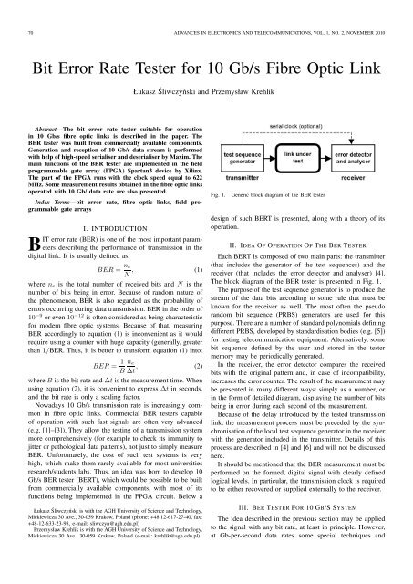
Fig. 1. Generic block diagram of the BER tester.<br />
design of such BERT is presented, along with a theory of its<br />
operation.<br />
II. IDEA OF OPERATION OF THE BER TESTER<br />
Each BERT is composed of two ma<strong>in</strong> parts: the transmitter<br />
(that <strong>in</strong>cludes the generator of the test sequences) and the<br />
receiver (that <strong>in</strong>cludes the error detector and analyser) [4].<br />
The block diagram of the BER tester is presented <strong>in</strong> Fig. 1.<br />
The purposeof the test sequence generatoris to producethe<br />
stream of the data bits accord<strong>in</strong>g to some rule that must be<br />
known <strong>for</strong> the receiver as well. The most often the pseudo<br />
random bit sequence (PRBS) generators are used <strong>for</strong> this<br />
purpose. There are a number of standard polynomialsdef<strong>in</strong><strong>in</strong>g<br />
different PRBS, developed by standardisation bodies (e.g. [5])<br />
<strong>for</strong> test<strong>in</strong>g telecommunication equipment. Alternatively, some<br />
bit sequence def<strong>in</strong>ed by the user and stored <strong>in</strong> the tester<br />
memory may be periodically generated.<br />
In the receiver, the error detector compares the received<br />
bits with the orig<strong>in</strong>al pattern and, <strong>in</strong> case of <strong>in</strong>compatibility,<br />
<strong>in</strong>creasesthe errorcounter.Theresult ofthemeasurementmay<br />
be presented <strong>in</strong> many different ways: simply as a number, or<br />
<strong>in</strong> the <strong>for</strong>m of detailed diagram, display<strong>in</strong>g the number of bits<br />
be<strong>in</strong>g <strong>in</strong> error dur<strong>in</strong>g each second of the measurement.<br />
Because of the delay <strong>in</strong>troduced by the tested transmission<br />
l<strong>in</strong>k, the measurement process must be preceded by the synchronisationofthelocaltest<br />
sequencegenerator<strong>in</strong>thereceiver<br />
with the generator <strong>in</strong>cluded <strong>in</strong> the transmitter. Details of this<br />
process are described <strong>in</strong> [4] and [6] and will not be discussed<br />
here.<br />
It should be mentioned that the BER measurement must be<br />
per<strong>for</strong>med on the <strong>for</strong>med, digital signal with clearly def<strong>in</strong>ed<br />
logical levels. In particular, the transmission clock is required<br />
to be either recovered or supplied externally to the receiver.<br />
III. BER TESTER FOR <strong>10</strong> GB/S SYSTEM<br />
The idea described <strong>in</strong> the previous section may be applied<br />
to the signal with any bit rate, at least <strong>in</strong> pr<strong>in</strong>ciple. However,<br />
at <strong>Gb</strong>-per-second data rates some special techniques and
ŚLIWCZYŃSKI AND KREHLIK: BIT ERROR RATE TESTER FOR <strong>10</strong> GB/S FIBRE OPTIC LINK 71<br />
Fig. 3. Structure of the s<strong>in</strong>gle word of the test sequence.<br />
Fig. 2. Simplified block diagram of <strong>10</strong> <strong>Gb</strong>/s BER tester.<br />
modifications of the basic idea must often be used, accord<strong>in</strong>g<br />
to the available technology. One of the most important th<strong>in</strong>gs<br />
when design<strong>in</strong>g the BER tester is the necessity to generate<br />
the serial data stream runn<strong>in</strong>g with <strong>10</strong> <strong>Gb</strong>/s rate. Hav<strong>in</strong>g no<br />
access to highly advanced technology of mak<strong>in</strong>g <strong>in</strong>tegrated<br />
circuit, it is practically impossible to build a classical PRBS<br />
generator based on the serial shift register with feedback. This<br />
difficulty may be overcome by design<strong>in</strong>g a generator and the<br />
error detector to operate on parallel words rather than on<br />
<strong>in</strong>dividual bits. Parallel data may then be easily converted <strong>in</strong>to<br />
the serial stream bymeansof properserialiser anddeserialiser.<br />
This way the speed of the clock necessary to operate the<br />
tester may be reduced substantially. In the solution described<br />
here<strong>in</strong>, it was assumed at first that generation and further data<br />
process<strong>in</strong>g would be per<strong>for</strong>med with 622 MHz clock us<strong>in</strong>g<br />
Xil<strong>in</strong>x’s Spartan3 FPGA (see Fig. 2). MAX3952/MAX3953<br />
serialiser/deserialiserbyMaximareresponsible<strong>for</strong>per<strong>for</strong>m<strong>in</strong>g<br />
serial/parallel conversion.<br />
Althoughsome<strong>in</strong>itialanalysissuggestedthatitwaspossible<br />
to build BERT accord<strong>in</strong>g to the diagram presented <strong>in</strong> Fig. 2,<br />
it turned out f<strong>in</strong>ally that full parallel architecture cannot<br />
be implemented <strong>in</strong> the Spartan3 device. Because of that, a<br />
modified and simplified architecture was developed, that fits<br />
<strong>in</strong>to chosen FPGA circuit. The most important features of this<br />
architecture will be presented <strong>in</strong> the next chapters.<br />
IV. TRANSMITTER WITH THE TEST SEQUENCES<br />
GENERATOR<br />
The full parallel PRBS architecture (e.g. as described <strong>in</strong><br />
[7]) proved to be too complex to operate with 622 MHz clock<br />
signal after implementation <strong>in</strong> Spartan3 FPGA. It was thus<br />
assumed that BER would be measured only on a few chosen<br />
bits (called the measurementchannels)fromthe 16-bitparallel<br />
word. It was also taken that the transmitter would repeat each<br />
16-bit sequence four times, which effectively lowers its clock<br />
speed to 155 MHz. This simplified greatly the test sequence<br />
generator.<br />
The structure of the parallel words sent to the serialiser<br />
is presented <strong>in</strong> Fig. 3. Inside this word two bits, D8 and<br />
D15, have their values fixed to “zero” and “one”, respectively.<br />
The BER of the l<strong>in</strong>k under test is determ<strong>in</strong>ed based on these<br />
two bits only. The rema<strong>in</strong><strong>in</strong>g 14 bits are divided <strong>in</strong>to two<br />
unequal fields, with length 8 and 6 bits. These fields are filled<br />
Fig. 4. <strong>10</strong> <strong>Gb</strong>/s BERT transmitter.<br />
with PRBS hav<strong>in</strong>g period 2 8 − 1 and 2 6 − 1, respectively.<br />
Such structure of the test word is justified by the requirement<br />
of hav<strong>in</strong>g the serial data stream as “random” as possible,<br />
simultaneouslypreserv<strong>in</strong>gitsDCbalance.Becauseofdifferent<br />
PRBS periods, the period of the result<strong>in</strong>g sequence is much<br />
longer than <strong>in</strong> the case of two PRBS with the same period.<br />
The structure of the test word proposed here<strong>in</strong> posseses<br />
some shortcom<strong>in</strong>gs, however. The longest run of the same<br />
consecutive symbols is limited to 9 “ones” and 7 “zeros”.<br />
It limits BERT capabilities when test<strong>in</strong>g the immunity of<br />
transmission system to the low frequencyspectral components<br />
conta<strong>in</strong>ed <strong>in</strong> the signal. Further, the number of bits that could<br />
result <strong>in</strong> <strong>in</strong>tersymbol <strong>in</strong>terference (ISI) is also limited: <strong>for</strong><br />
“one” there are 6 bits be<strong>for</strong>e and 8 bits after, <strong>for</strong> “zero” there<br />
is the reverse. These limitations, however, seem not to be a<br />
big problem, especially if the BERT is used to evaluate errors<br />
caused by fibre dispersion or laser chirp.<br />
A completeBERT transmitter<strong>in</strong>cludesalso a few additional<br />
blocks: pattern synchronisator, <strong>in</strong>verter and error <strong>in</strong>serter. The<br />
<strong>in</strong>verter is useful if the transmission l<strong>in</strong>k under test <strong>in</strong>verts<br />
the signal itself. This may be easily done even accidentally<br />
because I/O <strong>in</strong>terfaces of the BERT use differential signal<strong>in</strong>g.<br />
The error <strong>in</strong>serter allows <strong>for</strong> per<strong>for</strong>m<strong>in</strong>g some k<strong>in</strong>d of BERT<br />
self-test. If activated, it periodically changes the polarity of<br />
signals<strong>in</strong> the measurementchannels<strong>for</strong>one clockperiod,thus<br />
<strong>for</strong>c<strong>in</strong>g errors. Because the rate of these errors is known, it<br />
may be used to check <strong>for</strong> possible BERT or l<strong>in</strong>k under test<br />
malfunction. The pattern synchronization is necessary to align<br />
the bits at the output of the MAX3953 deserialiser with <strong>in</strong>puts<br />
of MAX3952 serialiser. When the deserialiser acquires serial<br />
synchronism with the data stream produced by the serialiser,<br />
thepositionofbitsatitsoutputisnotnecessarilycorrect.Thus,<br />
some k<strong>in</strong>d of a barrel shifter, capable of the rotation of bits<br />
appear<strong>in</strong>g at the output of the transmitter, is necessary to set<br />
the proper order of the bits. Although this circuit is associated<br />
rather with the deserialiser than serialiser, it appeared much<br />
easier to implement it <strong>in</strong>side the BERT transmitter.
72 ADVANCES IN ELECTRONICS AND TELECOMMUNICATIONS, VOL. 1, NO. 2, NOVEMBER 20<strong>10</strong><br />
Fig. 5. <strong>10</strong> <strong>Gb</strong>/s BERT receiver.<br />
V. BER DETECTOR AND ANALYSER<br />
Because of the structure of the test word used <strong>in</strong> the<br />
presented design, the detection of errors is a straight<strong>for</strong>ward<br />
task. To do this, it is enough to count the clock periods where<br />
the bits <strong>in</strong> the measurement channels differ from that set <strong>in</strong><br />
the transmitter.<br />
It is crucial <strong>for</strong> the BERT operation to run error counters<br />
at the clock speed equal to 622 MHz. To facilitate operation<br />
with such speed, the count<strong>in</strong>g of errors is divided <strong>in</strong>to a few<br />
tasks (see Fig. 5). At the <strong>in</strong>put of each measurement channel a<br />
3-bit fast counter is implemented. The Johnson’s counters are<br />
used there because of their potential <strong>for</strong> high-speed operation.<br />
Simulations per<strong>for</strong>med us<strong>in</strong>g ISE7 and ModelSim XE software<br />
packages (available <strong>for</strong>m Xil<strong>in</strong>x and Mentor Graphics,<br />
respectively) showed that the counter composed of maximum<br />
of three D flip-flops (F/F) is capable to operate with required<br />
speed. The capacity of such Johnson counter equals 6. This<br />
allows the lower<strong>in</strong>g of the clock<strong>in</strong>g speed of the rest of the<br />
circuit four times (blocksoperat<strong>in</strong>gwith lower clock speed are<br />
marked with additional dashed border <strong>in</strong> Fig. 5). The counter<br />
used <strong>in</strong> the design is the synchronousone, with <strong>in</strong>put from the<br />
measurement channel connected to the Clock Enable <strong>in</strong>puts of<br />
the F/F.<br />
To obta<strong>in</strong> the number of bits be<strong>in</strong>g <strong>in</strong> error dur<strong>in</strong>g the<br />
four consecutive clock cycles, it is necessary to calculate the<br />
difference between the current state of the Johnson’s counter<br />
and its delayed state. To facilitate this operation, the output<br />
from the counter is converted <strong>in</strong>to the natural b<strong>in</strong>ary <strong>for</strong>mat.<br />
After subtraction, the partial results are totaled <strong>in</strong> the 16-bit<br />
b<strong>in</strong>ary counter. The totalizer has two 3-bit <strong>in</strong>puts, one <strong>for</strong> each<br />
measurementchannel(process<strong>in</strong>gthe circuitry<strong>for</strong> onechannel<br />
only is shown <strong>in</strong> Fig. 5).<br />
VI. EDITORIAL POLICY<br />
After total<strong>in</strong>g the errors, the result is passed to the software<br />
PicoBlaze [8] processor implemented <strong>in</strong> the FPGA. This<br />
processor is responsible <strong>for</strong> calculat<strong>in</strong>g BER, display<strong>in</strong>g the<br />
result and communicat<strong>in</strong>g with the user.<br />
BER calculation is made accord<strong>in</strong>g to the <strong>for</strong>mula similar<br />
to that given <strong>in</strong> equation (2):<br />
BER = L 1 n e<br />
N A B ∆t , (3)<br />
where L is the length of the parallel word and N A is the<br />
numberof channelsmeasur<strong>in</strong>g BER. Modificationof the basic<br />
<strong>for</strong>mula (2) results from the fact that BERT described <strong>in</strong> the<br />
paper does not count all errors occurr<strong>in</strong>g dur<strong>in</strong>g the transmission.<br />
It rather samples errors that degrade transmission<br />
on two chosen bits only. Tak<strong>in</strong>g the assumption that the<br />
probability of errors affect<strong>in</strong>g the rest of bits is the same<br />
and that errors are <strong>in</strong>dependent, one may correct the result<br />
by simply <strong>in</strong>creas<strong>in</strong>g the error rate, as it is done <strong>in</strong> equation<br />
(3).<br />
In our case L = 16, N A = 2, B = <strong>10</strong> · <strong>10</strong> 9 and ∆t was<br />
chosen to be measured <strong>in</strong> seconds. Putt<strong>in</strong>g all these numbers<br />
<strong>in</strong>to equation (3), it may be simplified as:<br />
BER = 4 5 ∆t <strong>10</strong>−9 . (4)<br />
Us<strong>in</strong>g equation (4), BER may be quite easily calculated because<br />
all required mathematical operationsare per<strong>for</strong>medwith<br />
the natural numbers. Multiplicationby 4 <strong>in</strong> the numeratormay<br />
be carried out by the logical left shift of n e by two positions,<br />
whereas multiplication by 5 <strong>in</strong> the denom<strong>in</strong>ator requires two<br />
shifts and one more addition. The division operation must<br />
be per<strong>for</strong>med hav<strong>in</strong>g <strong>in</strong> m<strong>in</strong>d a possibly very wide, be<strong>in</strong>g <strong>in</strong><br />
orders of magnitude, dynamic range of the result. However,<br />
becausethereisalotoftimetoobta<strong>in</strong>theresult(1second),the<br />
entire operation may be executed without resort<strong>in</strong>g to the full<br />
float<strong>in</strong>g po<strong>in</strong>t arithmetic. A simple procedure implemented <strong>in</strong><br />
the design, exploits only multiplication by <strong>10</strong> and subtraction<br />
and allows calculate BER directly <strong>in</strong> the decimal x.xx · <strong>10</strong> −y<br />
<strong>for</strong>mat.Thecode<strong>for</strong>thisprocedurerealized<strong>in</strong>24-bitprecision<br />
occupies about 150 PicoBlaze assembler <strong>in</strong>structions and<br />
executes <strong>in</strong> a small fraction of second.<br />
n e<br />
VII. EXPERIMENTAL RESULTS<br />
Us<strong>in</strong>g the BERT described above, some experimental data<br />
were taken <strong>in</strong> l<strong>in</strong>ksoperat<strong>in</strong>gwith <strong>10</strong><strong>Gb</strong>/s transmissionspeed.<br />
The results are presented <strong>in</strong> Fig. 6.<br />
In Fig. 6a BER measured <strong>in</strong> the l<strong>in</strong>k composed of the laser<br />
transmitter followed by erbium doped fibre amplifier (EDFA)<br />
booster and 40 km of the standard s<strong>in</strong>glemode fibre (SSM)<br />
is presented. The two curves are plotted <strong>for</strong> two different<br />
values of EDFA ga<strong>in</strong>. Based on the plot, the power penalty<br />
may be determ<strong>in</strong>ed. For the case presented this penalty is<br />
quite <strong>in</strong>dependent of the <strong>in</strong>put power and is about -2 dB.<br />
The negative value of the penalty results probably from a<br />
constructive <strong>in</strong>teraction of fibre nonl<strong>in</strong>earity/dispersion with<br />
the chirp of directly modulated laser.<br />
When per<strong>for</strong>m<strong>in</strong>g BER measurements, some care must be<br />
taken, however. In Fig. 6b the results of back-to-back BER<br />
measurement with neither fibre nor EDFA <strong>in</strong>serted between<br />
the transmitter and the receiver are presented. Two different<br />
results were obta<strong>in</strong>ed <strong>in</strong> exactly the same experimental setup.<br />
Between two measurements, only the connector <strong>in</strong> the optical<br />
path was disconnected and connected aga<strong>in</strong>. The difference is<br />
probably caused by the light backreflected from the connector<br />
tothelaser. Thisgeneratessomenoise<strong>in</strong>thelaserthatstrongly<br />
depends on the quality of the optical connection. This is<br />
evident, thus, that any conclusions concern<strong>in</strong>g the penalties<br />
<strong>in</strong> the order of 1 dB should be drawn very carefully. It would<br />
be best to per<strong>for</strong>m measurements a few times, observ<strong>in</strong>g the<br />
consistence of the results.
ŚLIWCZYŃSKI AND KREHLIK: BIT ERROR RATE TESTER FOR <strong>10</strong> GB/S FIBRE OPTIC LINK 73<br />
quality, caused by a <strong>in</strong>teraction of directly modulated laser<br />
chirp with fibre dispersion. This, however, does not limit the<br />
applications of the BERT to these cases only.<br />
The architecture of the BERT described here<strong>in</strong> was tailored<br />
to the abilities of Spartan3 FPGA, that is used to implement<br />
most of the design. The usual operat<strong>in</strong>g idea of the BERT<br />
was found to be unsuitable <strong>for</strong> the design, there<strong>for</strong>e some<br />
special solutions were proposed. Us<strong>in</strong>g high-speed SiGe serialiser/deserialiser<br />
and exploit<strong>in</strong>g extensively parallel architecture<br />
with pipel<strong>in</strong><strong>in</strong>g, it was possible to overcome <strong>in</strong>herent<br />
speed limits of Spartan3 FPGA and build functional BERT<br />
operat<strong>in</strong>g at <strong>10</strong> <strong>Gb</strong>/s data rate.<br />
The tester built accord<strong>in</strong>g to the idea presented <strong>in</strong> the paper<br />
was tested <strong>in</strong> the laboratory and proved its usefulness <strong>for</strong><br />
research and <strong>in</strong>vestigation purposes. The design lacks some<br />
features, however, that should be added <strong>in</strong> the next version.<br />
Because BER measurements are relatively time-consum<strong>in</strong>g, it<br />
would be very helpful to log past values of BER <strong>for</strong> further<br />
analysis. This way, it would be possible to tell if the measured<br />
BER is <strong>in</strong>herent <strong>for</strong> the system under test, or if it was caused<br />
by some external <strong>in</strong>terference. In addition, the capacity of<br />
the totalizer (16 bits) proved to be too small and should be<br />
extended to 24 bits.<br />
REFERENCES<br />
Fig. 6. BER versus received optical power <strong>in</strong> a few experimental setups<br />
–desription <strong>in</strong> the text.<br />
VIII. CONCLUSION<br />
The bit error rate tester designed <strong>for</strong> operation <strong>in</strong> <strong>10</strong> <strong>Gb</strong>/s<br />
fibre optic l<strong>in</strong>ks is described <strong>in</strong> the paper. The ma<strong>in</strong> purpose<br />
of this BERT was to evaluate the degradation of the signal<br />
[1] “BERTScope S,” [onl<strong>in</strong>e], http://www.bertscope.com.<br />
[2] “ParBERT,” [onl<strong>in</strong>e], http://www.agilent.com.<br />
[3] “J-BERT N4903A,” [onl<strong>in</strong>e], http://www.agilent.com.<br />
[4] C. Coombs, Electronic Instrument Handbook. McGraw-Hill, 1995.<br />
[5] “ITU-T Recommendations O151, O152 and O153,” Tech. Rep.<br />
[6] A. Liwak and L. Śliwczyński, “Laboratoryjny miernik bitowej stopy<br />
błędu,” <strong>in</strong> Proc. of Poznańskie Warsztaty Telekomunikacyjne, 2004, pp.<br />
75–80, (<strong>in</strong> Polish).<br />
[7] L. Śliwczyński, “PRBS generator runs at 1.5 <strong>Gb</strong>ps,” <strong>in</strong> Proc. of EDN,<br />
Mar. 2007, pp. 76–80.<br />
[8] PicoBlaze 8-bit Embedded Microcontroller User Guide <strong>for</strong> Spartan-3,<br />
Virtex-II, and Virtex-II Pro FPGAs, Xil<strong>in</strong>x, 2005.