
Create successful ePaper yourself
Turn your PDF publications into a flip-book with our unique Google optimized e-Paper software.
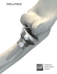
<strong>ACU</strong>-<strong>LoCt</strong><br />
TARGETED DISTAL RADIUS SYSTEM
<strong>ACU</strong>-<strong>LoCt</strong><br />
Targeted Distal Radius System<br />
Since 1988 Acumed has been<br />
designing solutions to the<br />
demanding situations facing<br />
orthopedic surgeons, hospitals<br />
and their patients. Our<br />
strategy has been to know the<br />
indication, design a solution to<br />
fit, and deliver quality<br />
products and instruments.<br />
In a continuing effort to advance<br />
orthopedics,Acumed introduces<br />
the Acu-Loc Targeted Distal<br />
Radius Plate. The plate has several<br />
key features that contribute<br />
to an overall stable construct,<br />
ultimately benefiting the patient.<br />
Our goal was to design a plate<br />
that incorporated both a locking<br />
construct and a screw trajectory<br />
that maximized purchase in the<br />
distal fragments, with a targeting<br />
guide that aided the surgeon and<br />
improved the surgical technique.<br />
The launch of the Acu-Loc plate<br />
and its comprehensive, unique<br />
instrumentation system brings to<br />
orthopedics an advancement in<br />
the treatment of distal radius<br />
fractures. The implants and<br />
instruments are an extension of<br />
Acumed’s philosophy to bring to<br />
the market an innovative product<br />
that addresses the issues<br />
with current treatment methods<br />
for a specific indication.<br />
With the Acu-Loc Targeted Distal Radius Plate, Acumed has designed an innovative<br />
solution for repairing fractures of the distal radius. Both the Acu-Loc<br />
plate and the instrumentation system contain several key features that address<br />
the issues faced with other plating techniques. Acumed recognized these<br />
issues and designed a solution that attends to these difficulties while also<br />
embracing innovation.<br />
When designing the Acu-Loc plates,Acumed’s goal was to design a better<br />
implant for the patient while improving the overall procedure for the surgeon.<br />
The anatomic design of the titanium plate, in conjunction with precise<br />
screw positioning and locking capabilities, creates an extremely stable construct<br />
with minimal soft tissue irritation. The unique targeting device minimizes<br />
O.R. time and improves the surgical technique.<br />
Acumed’s precise screw positioning<br />
and angulation targets the distal<br />
fragments and provides secure,<br />
stable fracture fixation. Two of the<br />
distal screws specifically target the<br />
radial styloid to provide fixation<br />
along the entire distal radius. The<br />
screw positioning ensures that<br />
most fragments can be captured<br />
by a locking or non-locking screw.<br />
2
SCREW PLACEMENT<br />
The Acu-Loc plate is designed<br />
to be placed more distal than<br />
many other volar plates. The<br />
distal screws, angled forward<br />
six degrees from the plate,<br />
maximize purchase in the subchondral<br />
bone. The unique<br />
distal screw placement maximizes<br />
stability and captures<br />
the radial styloid for a complete<br />
fixation solution.<br />
In order to improve fixation and pull-out strength and minimize soft tissue<br />
irritation,Acumed chose to give the surgeon options for proximal screw<br />
placement. The proximal holes in the plate are threaded to accept 3.5mm<br />
unicortical locking screws or traditional 3.5mm bicortical fixation. The<br />
screw holes are angled to maximize pull-out strength, improving overall<br />
plate stability. When combined with the Acu-Loc’s distal screw placement,<br />
the plate provides maximum fixation to promote fracture union.<br />
2.3mm gold fully<br />
threaded locking<br />
screws have the<br />
same pitch from<br />
tip to tail and are<br />
tapered under the<br />
head to facilitate<br />
insertion.<br />
2.3mm silver<br />
non-locking screw<br />
with enlarged tail<br />
end to minimize<br />
the toggle effect.<br />
2.3mm bronze<br />
smooth locking<br />
peg for optional<br />
distal fragment<br />
fixation. Pegs are<br />
tapered under the<br />
head to facilitate<br />
insertion.<br />
3.5mm aqua<br />
proximal locking<br />
screws have the<br />
same pitch from<br />
tip to tail and are<br />
tapered under the<br />
head to facilitate<br />
insertion.<br />
3.5mm silver<br />
non-locking<br />
cortical screws<br />
for bicortical<br />
proximal fixation.<br />
4
ADVANCED INSTRUMENTATION<br />
K-Wire<br />
Holes<br />
Targeting Guide<br />
Set Screw<br />
Distal Targeting<br />
Holes<br />
Dual Hole for Radial<br />
Styloid Screws<br />
Right Plate/Targeting Guide<br />
The Acu-Loc Targeted Distal<br />
Radius System features a<br />
unique targeting system for<br />
precise drilling and screw<br />
placement. All distal screws<br />
can be targeted using a single<br />
targeting guide, eliminating<br />
the time and frustration with<br />
traditional drilling and screw<br />
placement techniques. The<br />
guide allows the surgeon to<br />
accurately and consistently<br />
target and insert all eight distal<br />
screws.<br />
The targeting guide has several features that contribute to an improved surgical technique for the surgeon.<br />
The distal K-wire holes in both the targeting guide and the plate allows placement of one or more K-wires<br />
for provisional stability and to verify the positioning of the plate. The K-wire holes are in line with the distal<br />
screws, allowing the surgeon to verify the location of the most distal screws. The targeting guide also features<br />
a dual hole, allowing accurate placement of the two radial styloid screws. The targeting guides are left<br />
and right specific, with one guide to accommodate for the standard and long plates and a second guide to<br />
accommodate the wide plate. The targeting guides are housed next to the appropriate plates in the base of<br />
the tray for ease of use.<br />
The Acu-Loc instrumentation system gives the surgeon a<br />
comprehensive, complete set of instruments to implant<br />
the plate. The system features a number of clamps,<br />
retractors and soft tissue protectors in addition to the<br />
drivers, drills and targeting device. Acumed’s goal is to<br />
have one self-contained kit with everything needed for a<br />
case, eliminating the hassle of opening other instrumentation<br />
sets for additional components.
ANATOMICAL DESIGN<br />
Supports the<br />
curvature of the<br />
volar-ulnar lip.<br />
Accommodates and<br />
supports the radial<br />
styloid.<br />
The Acu-Loc plate is pre-contoured to match the anatomy of the patient. Acumed’s goal was to design a<br />
plate that most closely replicated the anatomical contours of the distal radius in order to maximize support<br />
and accurately reduce the fracture.<br />
When compared to traditional T-shaped plates, the Acu-Loc addresses the key anatomical structures of the<br />
distal radius. The shape of the plate allows it to sit more distal than many other volar plates, allowing the<br />
screws to capture and support the subchondral bone. The distal portion of the plate has surface variations<br />
to accommodate for the contours of the radius.<br />
Acumed conducted extensive cadaveric research to determine how to best match the complex anatomy of<br />
the distal radius. The plate surface is angled upward to accommodate and support the radial styloid. The<br />
plate surface is angled back to accommodate the anatomical fluctuations of the volar-ulnar lip, which differs<br />
from patient to patient.<br />
6
BIOMECHANICAL STUDIES<br />
The ability of locked screws to resist the loads in the distal radius has been shown in several studies that<br />
compared the average construct failure load of several plates on the market. Acumed simulated the testing<br />
methods used in these studies to determine the failure load of the Acu-Loc plate.<br />
Biomechanical Testing<br />
The failure load of the Acu-Loc plate was compared<br />
with the results of two recent biomechanical<br />
studies.<br />
In the first study 1 , the biomechanical properties of<br />
six dorsal and volar plate designs were compared<br />
(Table 1 * ). Average construct failure load of the<br />
six plates was measured. The study stated that an<br />
estimated 250 N is the amount of force that is<br />
applied to the wrist joint in the flexed digit position.<br />
Testing conducted on the Acu-Loc plate<br />
resulted in a construct load of 2400 N without<br />
failure. This shows that the Acu-Loc can withstand<br />
nearly 9X the force that is applied to the wrist<br />
during patient rehabilitation. All plates, including<br />
the Acu-Loc, exceeded this 250 N benchmark.<br />
The six plates in the study failed in a similar fashion.<br />
Bending of the plates occurred without screw<br />
loosening.<br />
The Acu-Loc’s biomechanical results were also<br />
compared to the results of a second biomechanical<br />
study 2 . In this study, the average construct failure<br />
load of three volar plate designs were compared<br />
(Table 2 * ). Screw loosening and bending<br />
occurred at the point of failure for the three<br />
plates studied.<br />
Table 1<br />
Table 2<br />
To determine the amount<br />
of force necessary to<br />
cause plate failure, the<br />
Acu-Loc plate was tested<br />
using a similar method<br />
described in two recent<br />
biomechanical studies.<br />
1.Osada, et. al. “Comparison of Different Distal Radius Dorsal and Volar Fracture<br />
Fixation Plates:A Biomechanical Study”. The Journal of Hand Surgery,Vol. 28A No. 1<br />
January 2003.<br />
2. Osada, et. al. “Biomechanics in Uniaxial Compression of Three Distal Radius Volar<br />
Plates”. The Journal of Hand Surgery,Vol. 29A No. 3 May 2004.<br />
* The charts from the two studies were reproduced by Acumed with the Acu-Loc<br />
information added for clarity.<br />
Summary<br />
The results of the biomechanical tests show that the Acu-Loc plate can withstand a force far beyond the<br />
loads that are seen in the radius during patient rehabilitation.<br />
7
SURGICAL TECHNIQUE<br />
<strong>ACU</strong>-<strong>LoCt</strong> TARGETED DISTAL RADIUS SYSTEM<br />
Step 1: The patient’s forearm is supinated to<br />
expose the surgical site. To maximize exposure, a<br />
towel is placed under the wrist placing it in extension.<br />
Make a longitudinal incision approximately<br />
six centimeters in length just radial to the FCR<br />
tendon to protect against potential injury to the<br />
palmar cutaneous branch of the median nerve.<br />
Step 2: The tendon sheath is opened and the<br />
tendon is retracted radially to protect the radial<br />
artery. The flexor pollicus longus is identified by<br />
passive flexion/extension of the thumb interphalangeal<br />
joint and is retracted ulnarly to protect<br />
the median nerve. Next, the pronator quadratus<br />
is identified by its transverse fibers and is released<br />
radial to ulnar to expose the fracture site.<br />
Step 3: The fracture is reduced and evaluated<br />
under fluoroscopy. The brachioradialis may need<br />
to be released from its insertion on the radial<br />
styloid to facilitate reduction and visualization.<br />
Long<br />
Wide<br />
Standard<br />
Narrow<br />
Step 4: There are four different plates in the set,<br />
each with a left and right option. Left plates are<br />
Blue, Right plates are Green. The standard plate<br />
(PL-DR50 L/R) is usually used. However, if the<br />
fracture extends proximally, the long plate (PL-<br />
DR60 L/R) may be needed. If the distal radius is<br />
wider or narrower than normal, the wide plate<br />
(PL-DR70 L/R) or the narrow plate (PL-DR30<br />
L/R) may be selected.<br />
8
William B. Geissler, M.D.<br />
Step 5: Once the plate is selected, the targeting<br />
guide is attached using the targeting<br />
guide set screw (PL-DRTS) following one of<br />
the three methods discussed. The standard<br />
and long plates use the same targeting<br />
guide (PL-DRT56 L/R) while the wide plate<br />
uses a sperate guide (PL-DRT70 L/R). The<br />
targeting guide may be attached to the<br />
plate on the back table prior to insertion<br />
and then placed on the bone. The plate’s<br />
position is then secured proximally and distally<br />
with K-Wires. An alternate method is<br />
to secure the plate to the bone with a cortical<br />
screw proximally and then attach the<br />
targeting guide. A third method is to<br />
secure the plate to the bone with a 0.045"<br />
K-Wire proximally and a 0.054" K-Wire<br />
distally. The guide then slides over the distal<br />
K-Wire and into position. Care should<br />
be taken not to angle the distal K-Wires.<br />
Step 6: The plate is made to sit along the<br />
distal aspect of the distal radius to support<br />
the volar articular fracture fragments. To<br />
temporarily hold the plate in place, a<br />
0.045" K-Wire may be placed through one<br />
of the small holes in the shaft of the plate.<br />
To assess the position of the distal locking<br />
screws relative to the articular surface, a<br />
0.054" K-Wire may be placed through the<br />
distal holes on the plate. The fracture<br />
reduction, position of the plate, and the<br />
location of the distal K-Wire relative to<br />
the joint is assessed under fluoroscopy. If<br />
the distal K-Wire does not penetrate the<br />
joint, the subsequent distal locking screws<br />
will not as well. Care should be taken that<br />
there is no soft tissue in the targeting<br />
guide.<br />
9
SURGICAL TECHNIQUE<br />
<strong>ACU</strong>-<strong>LoCt</strong> TARGETED DISTAL RADIUS SYSTEM<br />
Step 7: Place the first 3.5mm cortical<br />
screw through the slot in the plate. The<br />
position of the plate relative to the articular<br />
surface can then be fine tuned by sliding<br />
the plate proximal or distal under fluoroscopy.<br />
Using the 2.8mm drill (MS-DC28)<br />
and the drill guide (PL-2018), drill through<br />
the far cortex. Drill depth is measured<br />
with the depth gauge (MS-9020). Note<br />
that if provisional K-Wires are in place,<br />
they may interfere with drilling and screw<br />
insertion. Insert the appropriate silver<br />
3.5mm screw (CO-3xx0), taking care that<br />
the screw does not exit the bone dorsally.<br />
Step 8: Select one of the four screws<br />
closest to the joint to target first. There<br />
are three types of screws that can be used<br />
in any of the eight distal holes: Fully-<br />
Threaded Locking Screws, Smooth Locking<br />
Pegs and Non-Toggling Screws. Insert the<br />
drill guide (MS-DG23) into one of the<br />
holes, followed by the 2.0mm drill (MS-<br />
DCR20).<br />
10
William B. Geissler, M.D.<br />
Step 9: The depth of the screw is measured<br />
using the laser mark on the shaft of<br />
the drill and the scale on the drill guide.<br />
An alternative way to measure the screw<br />
length is by using the Depth Probe (MS-<br />
DRPB). The probe is inserted through the<br />
drill guide, hooking the far cortex. The<br />
screw length measurement is read from<br />
the laser mark on the probe. Both the<br />
probe and the drill guide are removed<br />
together prior to screw insertion.<br />
Step 10: A Gold Threaded Locking Screw<br />
(CO-T23xx) is inserted using the 1.5mm<br />
driver tip (HPC-0015), sleeve (MS-SS23)<br />
and driver handle (MS-2210). A Bronze<br />
Smooth Locking Peg (CO-S23xx), or a<br />
Silver Non-Locking Screw (CO-N23xx)<br />
may also be used.<br />
An alternative method to drilling the distal<br />
screws is available with the Acu-Loc plate.<br />
An Individual Locking Drill Guide (MS-<br />
LDG23) is available in the system that<br />
threads into the eight distal locking holes<br />
individually. Screw length can be read using<br />
the Depth Gauge (MS-9020).<br />
11
SURGICAL TECHNIQUE<br />
<strong>ACU</strong>-<strong>LoCt</strong> TARGETED DISTAL RADIUS SYSTEM<br />
2.3mm gold fully threaded locking screw<br />
with same pitch<br />
2.3mm silver non-locking screw with<br />
minimized toggle effect<br />
2.3mm bronze smooth<br />
locking peg<br />
Step 11: It is at the discretion of the surgeon<br />
when to use the Threaded Locking<br />
Screws, the Smooth Locking Pegs, and the<br />
Non-Toggling (non-locking) Screws. The<br />
thread pitch on the Threaded Locking<br />
Screw is the same from the tip to the head<br />
minimizing the "differential pitch effect" as<br />
the screw is tightened into the plate. All<br />
eight distal holes accept the three different<br />
screw designs.<br />
The radial styloid screws are designed<br />
specifically to target and support the radial<br />
styloid fragment at angles of 35 and 47<br />
degrees from the plate. A C-Arm overlay<br />
is available in the system to determine the<br />
trajectory of the distal/radial screw prior<br />
to screw insertion. The overlay is used<br />
with an A/P view of the distal radius.<br />
Note: A minimum of 6 distal screws should be used.<br />
Step 12: The two radial styloid screws are<br />
approached from the back of the targeting<br />
guide. Using the dual slot on the back of<br />
the guide, the distal/radial screw is targeted<br />
by inserting the drill guide to the radial<br />
side (1) of the dual slot. The more proximal/ulnar<br />
screw is targeted by inserting the<br />
drill guide to the ulnar side of the dual slot<br />
(2). Both radial styloid screws should be<br />
drilled through the targeting guide.<br />
Remove the guide to measure and insert<br />
the screws. The guide is removed to<br />
increase visualization of the drill holes<br />
when inserting the screws. With the targeting<br />
guide in place, it may be difficult to<br />
remove the radial styloid screws if a different<br />
size screw is needed. If resizing is necessary,<br />
remove the guide and the screw,<br />
measure with the depth gauge and insert<br />
the proper screw.<br />
12
William B. Geissler, M.D.<br />
Step 13: Select one of the two remaining<br />
proximal holes and insert the Threaded<br />
Drill Guide (MS-LDG35) if a locking screw<br />
is desired, or the Standard Drill Guide (PL-<br />
2018) if a non-locking screw is needed.<br />
Drill with the 2.8mm drill (MS-DC28) for<br />
either proximal screw.<br />
Step 14: Drill depth is measured with the<br />
depth gauge (MS-9020). Insert the appropriate<br />
Light Blue 3.5mm Locking Screw<br />
(COL-3xx0), taking care that the screw<br />
does not exit the bone dorsally. Insert the<br />
locking screw using the 2.5mm driver tip<br />
(HPC-0025), sleeve (MS-SS35) and driver<br />
handle (MS-3200). Using the same process,<br />
drill and place the final locking screw.<br />
13
SURGICAL TECHNIQUE<br />
<strong>ACU</strong>-<strong>LoCt</strong> TARGETED DISTAL RADIUS SYSTEM<br />
Step 15: Following thorough radiographic<br />
evaluation, the wound is closed.<br />
Start immediate finger range of motion<br />
and forearm rotation post-op. Allow<br />
early functional use of the hand for<br />
light ADLs. Support the wrist according<br />
to bone quality and stability.<br />
Pre-Op Radius Fracture<br />
Post-Op Radius Fracture with the<br />
<strong>ACU</strong>-LOC<br />
14
Precise Screw Placement enables the surgeon to maximize purchase<br />
in the distal radius and the radial styloid. Unicortical locking<br />
proximal screws provide stability while eliminating soft tissue impingement<br />
on the dorsal surface of the distal radius.<br />
Advanced Targeting Guide allows the surgeon to quickly target each of<br />
the eight distal screws, saving valuable O.R. time and frustration associated<br />
with individual targeting guides.<br />
Anatomical Plate Design assists in restoring the original geometry<br />
of the patient's anatomy. Extensive cadaveric research aided in the<br />
development of an anatomically contoured plate design. Left and Right<br />
specific plate options are available in the system that each precisely<br />
match the anatomical curvature of the distal radius.<br />
Distal row of<br />
screws/pegs.<br />
Targeted radial styloid screws.<br />
Color coded for left (blue) and right (green) application.<br />
Proximal row of<br />
screws/pegs stagger<br />
between distal row to<br />
maximize stability.<br />
K-wire holes for provisional stability and to ensure<br />
screws do not pass through the radial-carpal joint.<br />
Mounting hole for targeting guide.<br />
Low profile plate/screw interface.<br />
Targeting guide alignment hole.<br />
K-wire holes for<br />
provisional stability.<br />
Reduction slot.<br />
Static holes for proximal<br />
locking screws.<br />
Beveled plate edges to<br />
minimize irritation.<br />
Titanium Alloy<br />
3
Acu-Loc Distal Radius Plates<br />
2.3mm Smooth Peg<br />
PL-DR50L Standard Distal Radius Plate - Left CO-S2314 2.3mm Peg 14mm Long<br />
PL-DR50R Standard Distal Radius Plate - Right CO-S2316 2.3mm Peg 16mm Long<br />
PL-DR60L Long Distal Radius Plate - Left CO-S2318 2.3mm Peg 18mm Long<br />
PL-DR60R Long Distal Radius Plate - Right CO-S2320 2.3mm Peg 20mm Long<br />
PL-DR70L Wide Distal Radius Plate - Left CO-S2322 2.3mm Peg 22mm Long<br />
PL-DR70R Wide Distal Radius Plate - Right CO-S2324 2.3mm Peg 24mm Long<br />
PL-DR30L Narrow Distal Radius Plate - Left CO-S2326 2.3mm Peg 26mm Long<br />
PL-DR30R Narrow Distal Radius Plate - Right CO-S2328 2.3mm Peg 28mm Long<br />
Drill Bits<br />
2.3mm Threaded Locking Screw<br />
MS-DC28 2.8 mm Drill Bit CO-T2314 2.3mm Threaded Locking Screw 14mm Long<br />
MS-DCR20 2.0 mm Drill Bit CO-T2316 2.3mm Threaded Locking Screw 16mm Long<br />
CO-T2318 2.3mm Threaded Locking Screw 18mm Long<br />
CO-T2320 2.3mm Threaded Locking Screw 20mm Long<br />
K-Wires & Drill Guides CO-T2322 2.3mm Threaded Locking Screw 22mm Long<br />
WS-1106 .045 K-Wire CO-T2324 2.3mm Threaded Locking Screw 24mm Long<br />
WS-1406 .054 K-Wire CO-T2326 2.3mm Threaded Locking Screw 26mm Long<br />
MS-LDG23 Locking Drill Guide - Distal CO-T2328 2.3mm Threaded Locking Screw 28mm Long<br />
MS-LDG35 Locking Drill Guide - Proximal<br />
2.3mm Threaded Non-Toggling Screw<br />
CO-N2314 2.3mm Non-Toggling Screw 14mm Long<br />
3.5mm Cortical Screws CO-N2316 2.3mm Non-Toggling Screw 16mm Long<br />
CO-3100 3.5mm Cortical Screw 10mm Long CO-N2318 2.3mm Non-Toggling Screw 18mm Long<br />
CO-3120 3.5mm Cortical Screw 12mm Long CO-N2320 2.3mm Non-Toggling Screw 20mm Long<br />
CO-3140 3.5mm Cortical Screw 14mm Long CO-N2322 2.3mm Non-Toggling Screw 22mm Long<br />
CO-3160 3.5mm Cortical Screw 16mm Long CO-N2324 2.3mm Non-Toggling Screw 24mm Long<br />
CO-3180 3.5mm Cortical Screw 18mm Long CO-N2326 2.3mm Non-Toggling Screw 26mm Long<br />
CO-N2328 2.3mm Non-Toggling Screw 28mm Long<br />
3.5mm Locking Cortical Screws CO-N2330 2.3mm Non-Toggling Screw 30mm Long<br />
COL-3080 3.5mm Locking Cortical Screw 8mm Long CO-N2332 2.3mm Non-Toggling Screw 32mm Long<br />
COL-3100 3.5mm Locking Cortical Screw 10mm Long<br />
COL-3120 3.5mm Locking Cortical Screw 12mm Long<br />
COL-3140 3.5mm Locking Cortical Screw 14mm Long<br />
COL-3160 3.5mm Locking Cortical Screw 16mm Long<br />
COL-3180 3.5mm Locking Cortical Screw 18mm Long
AcUMEDr<br />
5885 N.W. Cornelius Pass Road<br />
Hillsboro, OR 97124-9432<br />
(888) 627-9957<br />
www.acumed.net<br />
Distributed by:<br />
Copyright © 2005<br />
Acumed is a registered trademark.<br />
All rights reserved.<br />
Patents pending.<br />
CPS00-03-02 Effective: 9/2005