
Create successful ePaper yourself
Turn your PDF publications into a flip-book with our unique Google optimized e-Paper software.
William B. Geissler, M.D.<br />
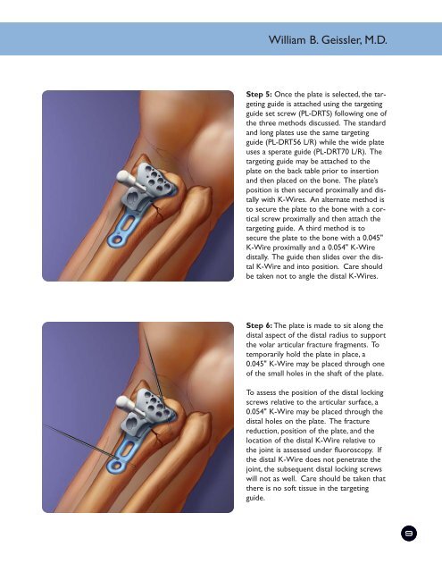
Step 5: Once the plate is selected, the targeting<br />
guide is attached using the targeting<br />
guide set screw (PL-DRTS) following one of<br />
the three methods discussed. The standard<br />
and long plates use the same targeting<br />
guide (PL-DRT56 L/R) while the wide plate<br />
uses a sperate guide (PL-DRT70 L/R). The<br />
targeting guide may be attached to the<br />
plate on the back table prior to insertion<br />
and then placed on the bone. The plate’s<br />
position is then secured proximally and distally<br />
with K-Wires. An alternate method is<br />
to secure the plate to the bone with a cortical<br />
screw proximally and then attach the<br />
targeting guide. A third method is to<br />
secure the plate to the bone with a 0.045"<br />
K-Wire proximally and a 0.054" K-Wire<br />
distally. The guide then slides over the distal<br />
K-Wire and into position. Care should<br />
be taken not to angle the distal K-Wires.<br />
Step 6: The plate is made to sit along the<br />
distal aspect of the distal radius to support<br />
the volar articular fracture fragments. To<br />
temporarily hold the plate in place, a<br />
0.045" K-Wire may be placed through one<br />
of the small holes in the shaft of the plate.<br />
To assess the position of the distal locking<br />
screws relative to the articular surface, a<br />
0.054" K-Wire may be placed through the<br />
distal holes on the plate. The fracture<br />
reduction, position of the plate, and the<br />
location of the distal K-Wire relative to<br />
the joint is assessed under fluoroscopy. If<br />
the distal K-Wire does not penetrate the<br />
joint, the subsequent distal locking screws<br />
will not as well. Care should be taken that<br />
there is no soft tissue in the targeting<br />
guide.<br />
9