Aluminum LSV-LSVG - VAHLE, Inc
Aluminum LSV-LSVG - VAHLE, Inc
Aluminum LSV-LSVG - VAHLE, Inc

You also want an ePaper? Increase the reach of your titles
YUMPU automatically turns print PDFs into web optimized ePapers that Google loves.
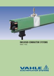
ENCLOSED CONDUCTOR SYSTEMS<br />
<strong>LSV</strong> and <strong>LSV</strong>G
ALUMINIUM ENCLOSED CONDUCTOR SYSTEMS<br />
INDEX<br />
Page<br />
Powerail versions (Photos) 2<br />
Technical Data 2<br />
Basic Description 3<br />
Powerail Cat.-Nos. and Weights 4<br />
Engineering Data and Configurations 5<br />
Standard Sections & Curves 6<br />
Joint Material 7<br />
Brackets 8<br />
Hangers 9<br />
End Caps 10<br />
End Feeds 10<br />
Line Feeds 11<br />
Transfer and switch Arrangements 12<br />
Transfer Funnels 13<br />
Transfer Guides, straight cut 14<br />
Page<br />
Transfer Guides, oblique cut 15<br />
Heating System 16<br />
Anti-condensation Sections 17<br />
Telescope Sections 18<br />
Expansion Joint Sections 19<br />
Collectors 20<br />
Double Collectors 21<br />
Tow Arms 22<br />
Flexible Tow Arm Configurations 23<br />
Sectionalizing 24<br />
Spare Parts 24<br />
Application Photos 25, 27<br />
Examples for ordering 26, 27<br />
Basic Dimensions 28<br />
Questionnaire 29, 30<br />
Type <strong>LSV</strong><br />
Type <strong>LSV</strong> with Plastic shielding “FP”<br />
Type <strong>LSV</strong>G<br />
Type <strong>LSV</strong>G with sealing strip “D”<br />
Technical Data<br />
Max. continuous current: 300 A (with 80% duty cycle)<br />
Nominal voltage:<br />
690 V<br />
Collector rating:<br />
40 A up to 80 A<br />
min. Bending Radius: <strong>LSV</strong> 750 mm/ <strong>LSV</strong>G 1500 mm<br />
Impedance:<br />
16 25 35 50 70 mm 2 copper<br />
1.17 0.72 0.53 0.38 0.28 Ohm/1000 m<br />
Temperature Resistance:<br />
Powerail – 40 °C up to + 100 °C (120 °C) (1)<br />
Sealing strip “D” up to + 80 °C<br />
Plastic shielding “FP” up to + 55 °C<br />
Collector – 40 °C/+ 70 °C (120 °C) (1)<br />
Resistance:<br />
16 25 35 50 70 mm 2 copper<br />
1.16 0.71 0.51 0.36 0.26 Ohm/1000 m<br />
Consider the voltage drop calculation to maintain the limits established by the motor manufacturers:<br />
Formulas:<br />
AC:<br />
DC:<br />
ΔU= 3 x I x l x Z<br />
Δ U 1<br />
= 2l x I x R<br />
ΔU 2<br />
=<br />
Δ U 1 · 100<br />
V<br />
Effective length:<br />
l = L power feed located at the end of the system<br />
l = L/2 power feed located at the mid-point of the system<br />
l = L/4 power feed located at both ends of the system<br />
l = L/6 power feed located at L/6 from each end<br />
of the system<br />
Δ U 1<br />
= Voltage drop [V] V = System Voltage<br />
Δ U 2<br />
= Voltage drop in % l = Power feed length [m] Z= Impedance in Ohm/1000 m<br />
I = Ampere load [A] L = System length [m] R= Resistance in Ohm/1000 m<br />
The total ampere load is determined from the nominal rated current of all motors working simultaneously on the same feed<br />
section of your electrification system.<br />
The number of feed points should be increased in case the drop is exceeding the limitations – or it may be necessary to provide<br />
booster cables.<br />
2<br />
(1)<br />
Consult factory for higher temperature applications.
POWERAIL <strong>LSV</strong> AND <strong>LSV</strong>G<br />
General<br />
The Vahle Aluminium enclosed powerails <strong>LSV</strong> and <strong>LSV</strong>G are compact<br />
and safe prefabricated Electrification Systems.<br />
These systems are ideal for indoor and outdoor use, for all types<br />
of installations requiring a moving or movable source of electrical<br />
power: cranes, monorails, hoists, electric power tools, machine<br />
tools, storage and retrieval systems and many other mobile machinery<br />
applications. <strong>LSV</strong> and <strong>LSV</strong>G are especially well suited for higher<br />
ambient temperatures.<br />
The principal advantages of these systems are maximum electrical<br />
and personnel safety, compactness, dependability and minimal<br />
maintenance expense. They fully meet all safety requirements; VDE<br />
0470 part 1; Protection IP 23, with sealing strip IP 24 per EN 60529<br />
applies.<br />
In special cases the plastic shielding FP provides additional safety.<br />
For the collectors applies protection against contact only if the brushes<br />
are complete in the conductor rail.<br />
Conductor rails in the hand area in which the collectors leave the<br />
powerail under normal service conditions, must have a protection<br />
agaist contact on site e.g. through barriers or disconnection. This is<br />
only necessary at voltages above 25 V AC or 60 V DC. Different<br />
cross section combinations, as shown on page 4 are possible. Please<br />
consider VDE 0100 part 430 in case of usig a N-pole.<br />
The aluminium enclosed <strong>LSV</strong> 4-pole and the PVC enclosed KSL 4-pole<br />
(see cat. 4a) can be combined by means of a transfer piece.<br />
Housing<br />
The system consists of two prefabricated, standardized aluminium<br />
profiles which are bolted together. The polarizing long and short lip<br />
profiles prevent accidental reversal and avoid phase reversing of<br />
collectors (see pages 5 & 6). The lateral arrangement of insulators<br />
and copper conductors allows 4-7 conductors in the <strong>LSV</strong> and 6-11<br />
conductors in the <strong>LSV</strong>G housing.<br />
The 5, 7, 9 and 11-pole systems use an uninsulated ground conductor<br />
(see page 5).<br />
Curved track sections to contour to almost any job requirement can<br />
be furnished to order.<br />
We do recommend the anodized version for installations in coastal<br />
areas, river valleys or other humid and aggressive environments.<br />
Heating systems for icing conditions are available.<br />
All <strong>LSV</strong> and <strong>LSV</strong>G housings can be equipped with a Neoprene sealing<br />
strip or a Plastic shielding as shown on page 6 of this catalog.<br />
Standard duct sections are 1, 2, 3 or 4 m long; other sections to<br />
coincide with your runway requirements are available.<br />
End caps close the open powerail ends.<br />
Couplings<br />
The 60, 100 and 140 Amp. systems use side fish plates for joining<br />
adjacent sections;<br />
Expansion Joint Sections<br />
These expansion joints can compensate for expansion and<br />
contraction difference between aluminium housing and copper<br />
conductors. They do not interrupt electric current flow.<br />
Telescope & Anti-condensation sections<br />
The telescope devices serve for length-compensation in high temperature<br />
fluctuations, for runs exceeding 200 m. For combined<br />
indoor/outdoor applications use the anti-condensation section.<br />
A separate feeding on both sides of these units is required.<br />
Contact Sections, Turntables, Switches<br />
Powerails for working areas and transfer applications see page 12.<br />
Sectionalizing<br />
Conductor dead sections are electrical interrupts of the conductor.<br />
Under normal operating conditions a cross over with collectors to<br />
switch the voltage off or on is only allowed with low power ratings<br />
(control current).<br />
Available as air gap version (5 mm), where the collector carbon bridges<br />
the gap, e.g. for mains.<br />
Also available as insulating piece version (30 mm). In this case the<br />
insulating piece is longer than the carbon and each powerail<br />
section can be separated electrically, e.g. for control.<br />
Collectors<br />
The collectors are made of impact resistant pvc.<br />
The power will be transfered through spring supported brushes. The<br />
connection takes place through connecting cables or connection<br />
boxes. The mechanical connection to the consumer are provided by<br />
towing arms.<br />
With following system requirements double collectors have to<br />
be used:<br />
- Transfers with switches and turntables<br />
- low voltages, frequency controlled drives<br />
- Transmission of data- and/or emergency stop signals<br />
- high electrical loads<br />
The length of the connecting cable should not exeed 3 m, if the<br />
fuse is not laid out for this rating. See DIN VDE 0100, part 430 and<br />
DIN EN 60204-32.<br />
(Note: A.m. appears often in systems with more than one collector.)<br />
The provided connecting cables are sufficient for the quoted nominal<br />
current. For the different layout systems have the reduction<br />
factor according to DIN VDE 0298-4 be considered.<br />
Safery notice<br />
Please ensure that the arrangement of the collectors<br />
(conductor rail) and collector arms made by the customer is according to<br />
the safety distance of min. 0.5 m to prevent the danger of crushing.<br />
The 200 and 300 Amp. systems exclusively use bolted joints<br />
(see mounting information).<br />
Feed Sets<br />
End feeds or line feeds are available.<br />
End feed boxes 4-11-pole are designed for max. 60 Amperes; line<br />
feed boxes rate from 60 to 300 Amperes. Space-saving line feeds<br />
with 2 m connection cables are available.<br />
The factory assembled 1 m feed-in tracks integrate in your system<br />
length.<br />
Brackets & Hangers<br />
We do recommend to use our standard supporting brackets, page<br />
8 for monorail and hoist applications.<br />
Standard support spacing is 2 m. Up to 3 m support spacing is possible<br />
when using joint covers for connecting the duct sections. Use<br />
one fix point hanger; all others are sliding hangers (see installation<br />
instructions).<br />
Note:<br />
In case of use in galvanising plants, pickle shops, aggressive<br />
environments, Installations in firedamp areas or underneath<br />
a drainage area and if low voltage is required we recommend<br />
to send us your enquiry with full details (see questionnaire on<br />
page 29/30).<br />
For the preperation of quotes and orders we require drawings if<br />
the conductor has curves, dead sections, turntables or switches.<br />
3
TYPES, ENGINEERING DATA AND CATALOG NUMBERS<br />
<strong>LSV</strong><br />
Ampacity No. of conductors x copper section mm 2<br />
Type HS w PE No. of Poles at 80 % ED<br />
SS w/o PE L1, L2, L3 L1, L2, L3<br />
(2)<br />
N Control-Line<br />
A<br />
<strong>LSV</strong> 4/ 60 HS 4 60 3 x 16 1 x 16 – –<br />
<strong>LSV</strong> 4/ 60 SS Control line 4 60 – – – 4 x 16<br />
<strong>LSV</strong> 4/100 HS 4 100 3 x 25 1 x 16 – –<br />
<strong>LSV</strong> 4/140 HS 4 140 3 x 35 1 x 16 – –<br />
<strong>LSV</strong> 4/200 HS (1) 4 200 3 x 50 1 x 25 – –<br />
<strong>LSV</strong> 4/300 HS (1) 4 300 3 x 70 1 x 50 – –<br />
<strong>LSV</strong> 5/ 60 HS 5 60 3 x 16 1 x 16 1 x 16 –<br />
<strong>LSV</strong> 5/100 HS 5 100 3 x 25 1 x 16 1 x 25 –<br />
<strong>LSV</strong> 5/140 HS 5 140 3 x 35 1 x 16 1 x 35 –<br />
<strong>LSV</strong> 5/200 HS (1) 5 200 3 x 50 1 x 16 1 x 50 –<br />
<strong>LSV</strong> 5/300 HS (1) 5 300 3 x 70 1 x 16 1 x 70 –<br />
<strong>LSV</strong> 6/ 60 HS 6 60 3 x 16 1 x 16 – 2 x 16<br />
<strong>LSV</strong> 6/ 60 SS Control line 6 60 – – – 6 x 16<br />
<strong>LSV</strong> 6/100 HS 6 100 3 x 25 1 x 16 – 2 x 16<br />
<strong>LSV</strong> 6/140 HS 6 140 3 x 35 1 x 16 – 2 x 16<br />
<strong>LSV</strong> 6/200 HS (1) 6 200 3 x 50 1 x 25 – 2 x 16<br />
<strong>LSV</strong> 7/ 60 HS 7 60 3 x 16 1 x 16 1 x 16 2 x 16<br />
<strong>LSV</strong> 7/100 HS 7 100 3 x 25 1 x 16 1 x 25 2 x 16<br />
<strong>LSV</strong> 7/140 HS 7 140 3 x 35 1 x 16 1 x 35 2 x 16<br />
<strong>LSV</strong> 7/200 HS (1) 7 200 3 x 50 1 x 16 1 x 50 2 x 16<br />
<strong>LSV</strong>G<br />
<strong>LSV</strong>G 6/ 60 HS 6 60 3 x 16 1 x 16 – 2 x 16<br />
<strong>LSV</strong>G 6/ 60 SS Control line 6 60 – – – 6 x 16<br />
<strong>LSV</strong>G 6/100 HS 6 100 3 x 25 1 x 16 – 2 x 16<br />
<strong>LSV</strong>G 6/140 HS 6 140 3 x 35 1 x 16 – 2 x 16<br />
<strong>LSV</strong>G 6/200 HS (1) 6 200 3 x 50 1 x 25 – 2 x 16<br />
<strong>LSV</strong>G 6/300 HS (1) 6 300 3 x 70 1 x 50 – 2 x 20<br />
<strong>LSV</strong>G 7/ 60 HS 7 60 3 x 16 1 x 16 1 x 16 2 x 16<br />
<strong>LSV</strong>G 7/100 HS 7 100 3 x 25 1 x 16 1 x 25 2 x 16<br />
<strong>LSV</strong>G 7/140 HS 7 140 3 x 35 1 x 16 1 x 35 2 x 16<br />
<strong>LSV</strong>G 7/200 HS (1) 7 200 3 x 50 1 x 16 1 x 50 2 x 16<br />
<strong>LSV</strong>G 7/300 HS (1) 7 300 3 x 70 1 x 16 1 x 70 2 x 20<br />
<strong>LSV</strong>G 8/ 60 HS 8 60 3 x 16 1 x 16 – 4 x 16<br />
<strong>LSV</strong>G 8/ 60 SS Control line 8 60 – – – 8 x 16<br />
<strong>LSV</strong>G 8/100 HS 8 100 3 x 25 1 x 16 – 4 x 16<br />
<strong>LSV</strong>G 8/140 HS 8 140 3 x 35 1 x 16 – 4 x 16<br />
<strong>LSV</strong>G 8/200 HS (1) 8 200 3 x 50 1 x 25 – 4 x 16<br />
<strong>LSV</strong>G 9/ 60 HS 9 60 3 x 16 1 x 16 1 x 16 4 x 16<br />
<strong>LSV</strong>G 9/100 HS 9 100 3 x 25 1 x 16 1 x 25 4 x 16<br />
<strong>LSV</strong>G 9/140 HS 9 140 3 x 35 1 x 16 1 x 35 4 x 16<br />
<strong>LSV</strong>G 9/200 HS (1) 9 200 3 x 50 1 x 16 1 x 50 4 x 16<br />
<strong>LSV</strong>G 10/ 60 HS 10 60 3 x 16 1 x 16 – 6 x 16<br />
<strong>LSV</strong>G 10/ 60 SS Control line 10 60 – – – 10 x 16<br />
<strong>LSV</strong>G 10/100 HS 10 100 3 x 25 1 x 16 – 6 x 16<br />
<strong>LSV</strong>G 10/140 HS 10 140 3 x 35 1 x 16 – 6 x 16<br />
<strong>LSV</strong>G 10/200 HS (1) 10 200 3 x 50 1 x 25 – 6 x 16<br />
<strong>LSV</strong>G 11/ 60 HS 11 60 3 x 16 1 x 16 1 x 16 6 x 16<br />
<strong>LSV</strong>G 11/100 HS 11 100 3 x 25 1 x 16 1 x 25 6 x 16<br />
<strong>LSV</strong>G 11/140 HS 11 140 3 x 35 1 x 16 1 x 35 6 x 16<br />
<strong>LSV</strong>G 11/200 HS (1) 11 200 3 x 50 1 x 16 1 x 50 6 x 16<br />
4<br />
(1)<br />
With bolted joints only other types can be delivered<br />
with bolted joints without surcharge (on request).<br />
(2)<br />
The ground conductor = PE is always connected to the<br />
powerail housing and marked accordingly. The ground bar is<br />
uninsulated in the case of 5-, 7-, 9- and 11-pole systems.<br />
Mounting configurations see pages 8, 11, 23, 28.
Nominal<br />
Voltage<br />
Leakage Path<br />
Weight<br />
Order- No.<br />
Configurations<br />
<strong>LSV</strong><br />
V<br />
mm<br />
kg/m<br />
690 45 3,000 190 00 •<br />
690 45 3,000 190 10 •<br />
690 45 3,400 190 04 •<br />
690 45 3,700 190 08 •<br />
690 45 4,300 190 61 •<br />
690 35 5,000 190 60 •<br />
690 45 3,150 190 01 •<br />
690 45 3,550 190 03 •<br />
690 45 3,850 190 05 •<br />
690 45 4,450 190 62 •<br />
690 35 5,150 190 63 •<br />
<strong>LSV</strong> 4-pole, 60-300 A<br />
<strong>LSV</strong> 5-pole, 60-300 A<br />
690 45 3,300 190 02 •<br />
690 45 3,300 190 11 •<br />
690 45 3,700 190 06 •<br />
690 45 4,000 190 64 •<br />
690 45 4,480 195 52 •<br />
690 45 3,450 190 07 •<br />
690 45 3,850 190 09 •<br />
690 45 4,250 190 65 •<br />
690 45 4,730 195 60 •<br />
<strong>LSV</strong> 6-pole, 60-200 A<br />
<strong>LSV</strong> 7-pole, 60-200 A<br />
690 45 5,150 180 00 •<br />
690 45 5,150 180 22 •<br />
690 45 5,450 180 01 •<br />
690 45 5,750 180 02 •<br />
690 45 6,300 180 03 •<br />
690 35 7,250 180 04 •<br />
690 45 5,300 180 05 •<br />
690 45 5,700 180 06 •<br />
690 45 6,100 180 07 •<br />
690 45 6,700 180 08 •<br />
690 35 7,400 180 09 •<br />
<strong>LSV</strong>G 6-pole, 60-300 A<br />
<strong>LSV</strong>G 7-pole, 60-300 A<br />
<strong>LSV</strong>G<br />
690 45 5,450 180 10 •<br />
690 45 5,450 180 23 •<br />
690 45 5,750 180 11 •<br />
690 45 6,050 180 12 •<br />
690 45 6,530 184 58 •<br />
690 45 5,600 180 13 •<br />
690 45 6,000 180 14 •<br />
690 45 6,400 180 15 •<br />
690 45 6,940 184 59 •<br />
<strong>LSV</strong>G 8-pole, 60-300 A<br />
<strong>LSV</strong>G 9-pole, 60-300 A<br />
690 45 5,750 180 16 •<br />
690 45 5,750 180 24 •<br />
690 45 6,050 180 17 •<br />
690 45 6,350 180 18 •<br />
690 45 6,830 184 60 •<br />
690 45 5,900 180 19 •<br />
690 45 6,300 180 20 •<br />
690 45 6,700 180 21 •<br />
690 45 7,240 184 61 •<br />
<strong>LSV</strong>G 10-pole, 60-300 A<br />
<strong>LSV</strong>G 11-pole, 60-300 A<br />
• Add last number (1, 2, 3, 4 m length suffix)<br />
in accordance to bars required.<br />
Numbers in parenthesis are used for<br />
control circuit applications.<br />
5
STANDARD SECTION MAX. 4 M<br />
CURVED SECTION<br />
<strong>LSV</strong><br />
”A"<br />
left<br />
plug-in joint housing 60 - 140 A<br />
short lip profile in front<br />
”B"<br />
right<br />
Custom built<br />
(2) bolted joint housing 60 - 300 A<br />
short lip<br />
Extra finish of <strong>LSV</strong>; surcharge Order- No.<br />
Supplements for <strong>LSV</strong>:<br />
short lip<br />
Type<br />
copper conductors with stainless steel cap<br />
Index E<br />
anodized housing<br />
Index I<br />
Order- No.<br />
Order- No. Order- No.<br />
60 A 200 A<br />
<strong>LSV</strong> 4-pole 190 660 194 754 194 755<br />
<strong>LSV</strong> 5-pole 190 670 194 756 194 757<br />
<strong>LSV</strong> 6-pole 190 660 194 758 –<br />
<strong>LSV</strong> 7-pole 190 670 194 760 –<br />
Illustration see page 2<br />
Type<br />
Weight kg/m<br />
Order- No.<br />
Neoprene sealing strip D 0,225 254 751<br />
Fastener for sealing strip (pair) 258 432<br />
Coupling for sealing strip for length exceeding 50 m 258 300<br />
Mounting trolley for sealing strip 258 345<br />
Plastic shielding (1) incl 0,260 196 574<br />
locking pin for plastic shielding FP<br />
surcharge<br />
min. horizontal<br />
radius: 750 mm<br />
Consult factory<br />
for vertical bends<br />
Support spacing<br />
750 up to max. 2000 mm,<br />
depending on the radius<br />
max. L = 3200 mm,<br />
max.
JOINT MATERIAL (2) 7<br />
Plug-in joints 60-140 A<br />
Bolted joints 60-300 A<br />
ground cable (1)<br />
<strong>LSV</strong><br />
ground cable (1) 4 or 6 plug-in joints<br />
4 or 6 sets Hardware 60 - 200 A<br />
200<br />
2 pegs<br />
1 set joint fish plate 2 pegs<br />
1 set joint cover<br />
4 sets Hardware 300 A<br />
110<br />
Type Weight kg Order- No.<br />
VBL 4/5 for 4- and 5-pole 0,110 195 244<br />
VBL 6/7 for 6- and 7-pole 0,140 195 246<br />
Type Weight Order- No. Order- No.<br />
kg<br />
anodized<br />
VBLS 4/5 for 4- and 5-pole 0,450 195 248 –<br />
VBLS/E 4/5 60-200 Amp. 0,450 – 195 255<br />
VBLS 6/7 for 6- and 7-pole 0,505 195 250 –<br />
VBLS/E 6/7 60-200 Amp. 0,505 – 195 259<br />
VBLSG 4/5 for 4- and 5-pole 0,605 195 252 –<br />
VBLSG/E 4/5 300 Amp. 0,605 – 195 256<br />
Plug-in joints 60-140 A<br />
Bolted joints 60-300 A<br />
ground cable (1) ground cable (1)<br />
<strong>LSV</strong>G<br />
6,8 or 10 plug-in joints<br />
230<br />
6,8 or 10 sets Hardware 60 - 200 A<br />
2 pegs<br />
1 set joint fish plate<br />
2 pegs<br />
114<br />
1 set joint cover<br />
6 sets Hardware 300 A<br />
Type Weight kg Order- No.<br />
VLG 6/7 for 6- and 7-pole 0,135 184 107<br />
VLG 8/9 for 8- and 9-pole 0,165 184 109<br />
VLG 10/11 for 10- and 11-pole 0,195 184 111<br />
Type Weight Order- No. Order- No.<br />
kg<br />
anodized<br />
VLGS 6/7 for 6- and 7-pole 0,665 184 113 –<br />
VLGS/E 6/7 60-200 Amp. 0,665 – 184 121<br />
VLGS 8/9 for 8- and 9-pole 0,720 184 115 –<br />
VLGS/E 8/9 60-200 Amp. 0,720 – 184 125<br />
VLGS 10/11 for 10- and 11-pole 0,770 184 117 –<br />
VLGS/E 10/11 60-200 Amp. 0,770 – 184 127<br />
VLGSG 6/7 for 6- and 7-pole 0,890 184 119 –<br />
VLGSG/E 6/7 300 Amp. 0,890 – 184 122<br />
(1)<br />
Yellow/green ground cable factory pre-assembled.<br />
(2)<br />
No joints required for uninsulated top conductors 5, 7, 9 and 11.<br />
Equel for power line and control line.
BRACKETS<br />
These brackets are easily bolted to any type of standard<br />
-beam.<br />
View without<br />
-beam<br />
<strong>LSV</strong> 4/300<br />
<strong>LSV</strong>G 6/300<br />
View without<br />
-beam<br />
<strong>LSV</strong> 4/300<br />
<strong>LSV</strong>G 6/300<br />
EHKL small claw version<br />
Type<br />
X<br />
mm<br />
L<br />
mm<br />
B max.<br />
mm<br />
Weight<br />
kg<br />
Order- No.<br />
for std.<br />
brackets<br />
Order- No.<br />
with small<br />
claw<br />
EHK 250 250 350 170 1,070 251 600 251 720<br />
EHK 300 300 400 170 1,150 251 610 251 730<br />
Attention:<br />
Make sure that hoist wheels have enough clearance.<br />
Use small claw if necessary!<br />
-rail of EHKL is identical to type S 1, Order- No.<br />
Select next larger size bracket when your -beam dimension<br />
B is more than 170 mm and up to 300 mm.<br />
<strong>LSV</strong><br />
<strong>LSV</strong>G<br />
EHK 400 400 500 170 1,300 251 620 251 740<br />
EHK 500 500 600 170 1,450 251 630 251 750<br />
EHK 600 600 700 170 1,600 251 640 251 760<br />
EHK 700 700 800 170 1,750 251 650 251 770<br />
EHK 750 750 850 170 1,820 251 660 251 780<br />
EHK 800 800 900 170 1,900 251 670 251 790<br />
8<br />
(1)<br />
max. width 84 mm resp. 88 mm for plug-in joints w/o joint plates.<br />
Dim. in parenthesis refer to bolted joints with joint plates (see illustration).
FIXPOINT HANGER (1) 9<br />
SLIDING HANGER (1)<br />
<strong>LSV</strong><br />
(2)<br />
(2)<br />
locating clamp<br />
65<br />
M 8<br />
65<br />
M 8<br />
Type<br />
Weight<br />
kg<br />
Order- No.<br />
Type<br />
Weight<br />
kg<br />
Order- No.<br />
FAL 0,150 190 120<br />
GAL 0,080 190 130<br />
All steel parts made of stainless steel.<br />
All steel parts made of stainless steel.<br />
<strong>LSV</strong>G<br />
(2)<br />
(2)<br />
70<br />
M 12<br />
locating clamp<br />
70<br />
M 12<br />
clamp<br />
clamp<br />
Type<br />
Weight<br />
kg<br />
Order- No.<br />
Type<br />
Weight<br />
kg<br />
Order- No.<br />
SAFG 0,410 180 310<br />
SAS 0,175 200 160<br />
Steel parts galvanized, clamp made of stainless steel.<br />
Steel parts galvanized, clamp made of stainless steel.<br />
(1)<br />
Illustrations show hangers mounted to powerail.<br />
(2)<br />
Flat washers only to be used in slotted holes.
END CAP (1) END FEED (2)<br />
c/w 1 m powerail<br />
<strong>LSV</strong><br />
L = LH version, R = RH version<br />
(see page 6)<br />
115<br />
Plastic cap with plug-in joints<br />
Type<br />
Weight<br />
kg<br />
Order- No.<br />
EKL 0,080 190 220<br />
115<br />
70<br />
1000<br />
Cable glands (cable Ø see table page 28):<br />
4 & 5-pole 1 x M 32<br />
6 & 7-pole 1 x M 32<br />
and 1 x M 255<br />
Aluminium cap with bolted joints<br />
Type<br />
Weight<br />
kg<br />
Order- No.<br />
EKLS 0,300 195 149<br />
EKLS/E 0,300 195 303<br />
Type (3)<br />
Type (3)<br />
Weight<br />
Order- No.<br />
A<br />
kg<br />
Order- No.<br />
Power line HS with PE<br />
Power line HS with PE<br />
KEL 4/60 L 192 150 KEL 4/60 R 60 3.35 190 140<br />
KEL 5/60 L 192 160 KEL 5/60 R 60 3.55 190 150<br />
KEL 6/60 L 192 170 KEL 6/60 R 60 3.75 190 160<br />
KEL 7/60 L 192 180 KEL 7/60 R 60 3.95 190 170<br />
Control line SS without PE Control line SS without PE<br />
KEL 4/60 L 190 240 KEL 4/60 R 60 3.35 190 250<br />
KEL 6/60 L 190 260 KEL 6/60 R 60 3.75 190 390<br />
<strong>LSV</strong>G<br />
L = LH version (1) , R = RH version<br />
(see page 6)<br />
190<br />
Plastic cap with plug-in joints<br />
Type<br />
Weight<br />
Order- No.<br />
kg<br />
EKLG 0,120 180 320<br />
150<br />
100<br />
1000<br />
Cable glands (cable Ø see table page 28):<br />
all types 1 x M 32<br />
and 1 x M 25<br />
Aluminium cap with bolted joints<br />
Type<br />
Weight<br />
kg<br />
Order- No.<br />
EKLGS 0,450 184 100<br />
EKLGS/E 0,450 184 177<br />
Type (3)<br />
Order- No.<br />
Type (3)<br />
Power line HS with PE<br />
Power line HS with PE<br />
KELG 6/60 L 180 330 KELG 6/60 R 60 6.05 180 340<br />
KELG 7/60 L 180 350 KELG 7/60 R 60 6.25 180 360<br />
KELG 8/60 L 180 370 KELG 8/60 R 60 6.40 180 380<br />
KELG 9/60 L 180 430 KELG 9/60 R 60 6.60 180 440<br />
KELG 10/60 L 180 450 KELG 10/60 R 60 6.80 180 460<br />
KELG 11/60 L 180 470 KELG 11/60 R 60 7.00 180 480<br />
Control line SS without PE Control line SS without PE<br />
KELG 6/60 L 180 390 KELG 6/60 R 60 6.05 180 400<br />
KELG 8/60 L 180 410 KELG 8/60 R 60 6.40 180 420<br />
KELG 10/60 L 180 490 KELG 10/60 R 60 6.80 180 500<br />
A<br />
Weight<br />
kg<br />
Order- No.<br />
10<br />
(1)<br />
Illustration shows end cap with standard section.<br />
(2)<br />
Above sections come ready assembled on 1m section and are part of the system length (see examples for ordering pages 26 and 27).<br />
(3)<br />
Suffix types e.g. KEL 4/60 L w/ PE KEL 4/60 L HS Order- No. 192 150.
LINE FEED (1)<br />
c/w 2 m feed-in cable and 1 m powerail<br />
LINE FEED (1)<br />
c/w terminal box and 1 m powerail<br />
170<br />
300<br />
20<br />
170<br />
300<br />
<strong>LSV</strong><br />
90<br />
1000<br />
cable size: 60 A 11.5 Ø 10 mm 2<br />
100 A 13.5 Ø 25 mm 2<br />
140 A 14.5 Ø 35 mm 2<br />
1000<br />
Cable glands (cable-Ø see table page 28)<br />
4 + 5-pole 1 x M 32 power line 60 A<br />
4 + 5-pole 1 x M 50 power line 100 und 140 A<br />
4 + 5-pole 1 x M 50 power line 200 A<br />
4 + 5-pole 1 x M 63 power line 300 A<br />
6 + 7-pole 1 x M 32 and 1 x M 25 power line 60 A<br />
6 + 7-pole 1 x M 50 and 1 x M 25 power line 100 und 140 A<br />
6 + 7-pole 1 x M 50 and 1 x M 25 power line 200 A<br />
4 + 6-pole 1 x M 32 control line 60 A<br />
200 A 18.0 Ø 50 mm 2 Cable glands (cable-Ø see table page 28)<br />
Type (2)<br />
A<br />
Weight Order- No.<br />
Type<br />
kg<br />
Weight Order- No.<br />
A kg<br />
Type (2) Weight<br />
A<br />
kg<br />
Order-No.<br />
Power line HS with PE<br />
Power line HS with PE<br />
Power line HS with PE<br />
LAL 4/ 60 60 5,65 195 060 LAL 6/ 60 60 6,65 195 067 NKL 4/ 60 60 4,40 195 074<br />
LAL 4/100 100 6,55 195 061 LAL 6/100 100 7,80 195 068 NKL 4/100 100 4,80 195 075<br />
LAL 4/140 140 7,40 195 062 LAL 6/140 140 8,45 195 069 NKL 4/140 140 5,10 195 076<br />
LAL 4/200 200 8,00 195 637 LAL 6/200 200 8,95 195 639 NKL 4/200 200 5,80 195 077<br />
LAL 4/300 300 8,75 196 460<br />
NKL 4/300 300 6,50 195 078<br />
LAL 5/ 60 60 6,10 195 064 LAL 7/ 60 60 7,15 195 071 NKL 5/ 60 60 4,60 195 080<br />
LAL 5/100 100 7,00 195 065 LAL 7/100 100 9,00 195 072 NKL 5/100 100 5,00 195 081<br />
LAL 5/140 140 8,25 195 066 LAL 7/140 140 9,25 195 073 NKL 5/140 140 5,30 195 082<br />
LAL 5/200 200 8,85 195 638 LAL 7/200 200 9,80 195 640 NKL 5/200 200 6,00 195 083<br />
LAL 5/300 300 9,75 196 682<br />
NKL 5/300 300 6,70 195 084<br />
Control line SS without PE<br />
LAL 4/ 60 60 5,65 195 063<br />
LAL 6/ 60 60 6,65 195 070<br />
Type (2)<br />
Weight<br />
A<br />
kg<br />
Power line HS with PE<br />
Order-No.<br />
NKL 6/ 60 60 4,80 195 085<br />
NKL 6/100 100 5,20 195 086<br />
NKL 6/140 140 5,50 195 087<br />
NKL 6/200 200 6,00 195 567<br />
NKL 7/ 60 60 5,00 195 089<br />
NKL 7/100 100 5,40 195 090<br />
NKL 7/140 140 5,70 195 091<br />
NKL 7/200 200 6,30 195 568<br />
Control line SS without PE<br />
NKL 4/ 60 60 4,40 195 079<br />
NKL 6/ 60 60 4,80 195 088<br />
192<br />
400<br />
35<br />
192<br />
400<br />
<strong>LSV</strong>G<br />
75<br />
1000<br />
1000<br />
Type (2) A<br />
Weight<br />
kg<br />
Power line HS with PE<br />
cable size: 60 A 11.5 Ø 10 mm 2<br />
100 A 13.5 Ø 25 mm 2<br />
140 A 14.5 Ø 35 mm 2<br />
200 A 18.0 Ø 50 mm 2<br />
LALG 6/ 60 60 8,60 183 949 LALG 9/ 60 60 10,15 183 960<br />
LALG 6/100 100 9,40 183 950 LALG 9/100 100 11,05 183 961<br />
LALG 6/140 140 10,30 183 951 LALG 9/140 140 12,15 183 962<br />
LALG 6/200 200 10,80 184 661 LALG 9/200 200 12,70 184 664<br />
LALG 6/300 300 11,95 185 713<br />
LALG 7/ 60 60 9,10 183 953 LALG 10/ 60 60 10,65 183 963<br />
LALG 7/100 100 10,10 183 954 LALG 10/100 100 11,45 183 964<br />
LALG 7/140 140 11,10 183 955 LALG 10/140 140 12,30 183 965<br />
LALG 7/200 200 11,65 184 662 LALG 10/200 200 12,80 184 665<br />
LALG 7/300 300 12,85 185 714<br />
LALG 8/ 60 60 9,60 183 956 LALG 11/ 60 60 11,15 183 967<br />
LALG 8/100 100 10,45 183 957 LALG 11/100 100 12,10 183 968<br />
LALG 8/140 140 11,30 183 958 LALG 11/140 140 13,15 183 969<br />
LALG 8/200 200 11,80 184 663 LALG 11/200 200 13,70 184 666<br />
Control line SS without PE<br />
LALG 6/60 60 8,60 183 952<br />
LALG 8/60 60 9,60 183 959<br />
LALG 10/60 60 10,65 183 966<br />
Type (2) Weight<br />
Order-No.<br />
A<br />
Order-No.<br />
kg<br />
6-11-pole 1 x M 32 and 1 x M 25 power line 60 A<br />
6-11-pole 1 x M 50 and 1 x M 25 power line 100 und 140 A<br />
6+ 7-pole 1 x M 50 and 1 x M 25 power line 200 A<br />
6+ 7-pole 1 x M 63 and 1 x M 25 power line 300 A<br />
6, 8 and 10-pole 2 x M 25 control line 60 A<br />
Type (2) Weight<br />
A<br />
kg Order-No. Type (2) Order-No.<br />
Power line HS with PE Power line HS with PE Power line HS with PE<br />
NKLG 6/ 60 60 6,75 184 983<br />
NKLG 6/100 100 7,05 184 985<br />
NKLG 6/140 140 7,35 185 029<br />
NKLG 6/200 200 7,90 185 031<br />
NKLG 6/300 300 8,85 185 079<br />
NKLG 7/ 60 60 6,95 185 033<br />
NKLG 7/100 100 7,25 185 035<br />
NKLG 7/140 140 7,55 185 037<br />
NKLG 7/200 200 8,10 185 039<br />
NKLG 7/300 300 9,05 185 081<br />
NKLG 8/ 60 60 7,15 185 041<br />
NKLG 8/100 100 7,45 185 043<br />
NKLG 8/140 140 7,75 185 045<br />
NKLG 8/200 200 8,25 185 047<br />
A<br />
Weight<br />
kg<br />
NKLG 9/ 60 60 7,35 185 049<br />
NKLG 9/100 100 7,65 185 051<br />
NKLG 9/140 140 7,95 185 053<br />
NKLG 9/200 200 8,50 185 055<br />
NKLG 10/ 60 60 7,55 185 057<br />
NKLG 10/100 100 7,85 185 059<br />
NKLG 10/140 140 8,15 185 061<br />
NKLG 10/200 200 8,65 185 063<br />
NKLG 11/ 60 60 7,75 185 065<br />
NKLG 11/100 100 8,05 185 067<br />
NKLG 11/140 140 8,35 185 069<br />
NKLG 11/200 200 8,90 185 071<br />
Control line SS without PE<br />
NKLG 6/ 60 60 6,75 185 073<br />
NKLG 8/ 60 60 7,15 185 075<br />
NKLG 10/ 60 60 7,55 185 077<br />
(1)<br />
Above sections come ready assembled on 1 m powerail section and are a part of the system length (see examples for ordering on pages 26 and 27).<br />
(2)<br />
Suffix types e.g. LAL 4/60 w/ PE LAL 4/60 HS Order- No. 195 060.<br />
11
R<br />
TRANSFER AND SWITCH ARRANGEMENTS<br />
Contact section( 1)<br />
w/o cond. (1)<br />
Contact area<br />
(1)<br />
w/o cond.<br />
Line feed Powerail Track<br />
Transfer funnel<br />
w/o cond.<br />
(1)<br />
Contact area<br />
(1)<br />
w/o cond.<br />
Turntable<br />
Transfer guide oblique cut<br />
Turntable frame<br />
Track<br />
b<br />
a<br />
Line feed<br />
max. 20 mm<br />
Powerail<br />
Sliding switch<br />
Transfer guide<br />
Transfer guide<br />
a<br />
Line feed<br />
a<br />
max. 20 mm gap<br />
Track<br />
Transfer guide oblique cut<br />
Switch frame<br />
Powerail<br />
α<br />
c<br />
Please submit drawings of transfer applications. Specify dimenions a, b, c, R and angle ( max. 50°)<br />
12<br />
(1)<br />
Transfer funnels must not be activated before collectors are fully engaged.<br />
Flexible support type tow arms (see page 22) for collectors are essential with contact sections.
TRANSFER FUNNEL (2)<br />
c/w 0.5 m powerail and joint material<br />
Towing arms KFM or KFML (see page 22) required. Lateral tolerance upto max. 15 mm, vertical tolerance upto max. 10 mm.<br />
Max. entry speed collector unit: 60 m/min.<br />
Connect the conductor to mains only if all carbons of the collector have full contact to the conductor rail.<br />
Arrangement see page 12.<br />
<strong>LSV</strong><br />
500<br />
„B“<br />
„A“<br />
500<br />
~ 290<br />
w/o cond<br />
125<br />
500<br />
500<br />
„<br />
„A“<br />
160<br />
160<br />
125<br />
125<br />
125<br />
~ 290<br />
w/o cond<br />
short lip<br />
short lip<br />
Illustration shows L. H. version<br />
short lip in front<br />
(see page 6)<br />
Illustration shows R. H. version<br />
short lip in front<br />
(see page 6)<br />
Type (2)<br />
Weight<br />
kg<br />
Power line HS with PE<br />
Order- No.<br />
ETL 4/ 60 L 1,450 192 890<br />
ETL 4/100 L 1,500 192 900<br />
ETL 4/140 L 1,600 192 910<br />
ETL 4/200 L 1,700 192 920<br />
ETL 4/300 L 1,800 192 930<br />
ETL 5/ 60 L 1,500 192 940<br />
ETL 5/100 L 1,550 192 950<br />
ETL 5/140 L 1,650 192 960<br />
ETL 5/200 L 1,750 192 970<br />
ETL 5/300 L 1,900 192 980<br />
Type (2)<br />
Weight<br />
kg<br />
Power line HS with PE<br />
Order-<br />
No.<br />
ETL 6/ 60 L 1,500 192 990<br />
ETL 6/100 L 1,600 193 000<br />
ETL 6/140 L 1,650 193 010<br />
ETL 6/200 L 1,750 195 610<br />
ETL 7/ 60 L 1,550 193 020<br />
ETL 7/100 L 1,600 193 030<br />
ETL 7/140 L 1,700 193 040<br />
ETL 7/200 L 1,820 195 612<br />
Control line SS without PE<br />
ETL 4/ 60 L 1,450 193 050<br />
ETL 6/ 60 L 1,500 193 060<br />
Type (2)<br />
Weight<br />
kg<br />
Power line HS with PE<br />
Order- No.<br />
ETL 4/ 60 R 1,450 193 070<br />
ETL 4/100 R 1,500 193 080<br />
ETL 4/140 R 1,600 193 090<br />
ETL 4/200 R 1,700 193 100<br />
ETL 4/300 R 1,800 193 110<br />
ETL 5/ 60 R 1,500 193 120<br />
ETL 5/100 R 1,550 193 130<br />
ETL 5/140 R 1,650 193 140<br />
ETL 5/200 R 1,750 193 150<br />
ETL 5/300 R 1,900 193 160<br />
Type (2)<br />
Weight<br />
kg<br />
Power line HS with PE<br />
Order- No.<br />
ETL 6/ 60 R 1,500 193 170<br />
ETL 6/100 R 1,600 193 180<br />
ETL 6/140 R 1,650 193 190<br />
ETL 6/200 R 1,750 195 611<br />
ETL 7/ 60 R 1,550 193 200<br />
ETL 7/100 R 1,600 193 210<br />
ETL 7/140 R 1,700 193 220<br />
ETL 7/200 R 1,820 195 613<br />
Control line SS without PE<br />
ETL 4/ 60 R 1,450 193 230<br />
ETL 6/ 60 R 1,500 193 240<br />
Towing arms KFM or KFML (see page 22) required. Lateral tolerance upto max. 15 mm, vertical tolerance upto max. 10 mm.<br />
Max. entry speed collector unit: 60 m/min.<br />
Connect the conductor to mains only if all carbons of the collector have full contact to the conductor rail.<br />
Arrangement see page 12.<br />
<strong>LSV</strong>G<br />
125<br />
~ 290<br />
w/o cond<br />
Illustration shows L. H. version<br />
short lip in front<br />
(see page 6)<br />
Type (2)<br />
Weight<br />
kg<br />
Order- No.<br />
Power line HS witht PE<br />
ETLG 6/ 60 L 2,500 181 970<br />
ETLG 6/100 L 2,550 181 990<br />
ETLG 6/140 L 2,650 182 010<br />
ETLG 6/200 L 2,750 182 030<br />
ETLG 6/300 L 2,950 182 050<br />
ETLG 7/ 60 L 2,550 182 070<br />
ETLG 7/100 L 2,600 182 090<br />
ETLG 7/140 L 2,700 182 110<br />
ETLG 7/200 L 2,800 182 130<br />
ETLG 7/300 L 2,950 182 150<br />
ETLG 8/ 60 L 2,600 182 170<br />
ETLG 8/100 L 2,650 182 190<br />
ETLG 8/140 L 2,700 182 210<br />
ETLG 8/200 L 2,800 184 620<br />
short lip<br />
Type (2)<br />
Weight<br />
kg<br />
Power line HS with PE<br />
Order- No.<br />
ETLG 9/ 60 L 2,600 182 230<br />
ETLG 9/100 L 2,700 182 250<br />
ETLG 9/140 L 2,750 182 270<br />
ETLG 9/200 L 2,870 184 621<br />
ETLG 10/ 60 L 2,650 182 290<br />
ETLG 10/100 L 2,700 182 310<br />
ETLG 10/140 L 2,750 182 330<br />
ETLG 10/200 L 2,850 184 622<br />
ETLG 11/ 60 L 2,650 182 350<br />
ETLG 11/100 L 2,750 182 370<br />
ETLG 11/140 L 2,800 182 390<br />
ETLG 11/200 L 2,920 184 623<br />
Control line SS without PE<br />
ETLG 6/ 60 L 2,500 182 410<br />
ETLG 8/ 60 L 2,600 182 430<br />
ETLG 10/ 60 L 2,650 182 450<br />
short lip<br />
Illustration shows R. H. version<br />
short lip in front<br />
(see page 6)<br />
Type (2)<br />
Weight<br />
kg<br />
Power line HS with PE<br />
Order- No.<br />
ETLG 6/ 60 R 2,500 181 980<br />
ETLG 6/100 R 2,550 182 000<br />
ETLG 6/140 R 2,650 182 020<br />
ETLG 6/200 R 2,750 182 040<br />
ETLG 6/300 R 2,950 182 060<br />
ETLG 7/ 60 R 2,550 182 080<br />
ETLG 7/100 R 2,600 182 100<br />
ETLG 7/140 R 2,700 182 120<br />
ETLG 7/200 R 2,800 182 140<br />
ETLG 7/300 R 2,950 182 160<br />
ETLG 8/ 60 R 2,600 182 180<br />
ETLG 8/100 R 2,650 182 200<br />
ETLG 8/140 R 2,700 182 220<br />
ETLG 8/200 R 2,800 184 624<br />
~ 290<br />
w/o cond<br />
125<br />
Type (2)<br />
Weight<br />
kg<br />
Power line HS with PE<br />
Order- No.<br />
ETLG 9/ 60 R 2,600 182 240<br />
ETLG 9/100 R 2,700 182 260<br />
ETLG 9/140 R 2,750 182 280<br />
ETLG 9/200 R 2,870 184 625<br />
ETLG 10/ 60 R 2,650 182 300<br />
ETLG 10/100 R 2,700 182 320<br />
ETLG 10/140 R 2,750 182 340<br />
ETLG 10/200 R 2,850 184 626<br />
ETLG 11/ 60 R 2,650 182 360<br />
ETLG 11/100 R 2,750 182 380<br />
ETLG 11/140 R 2,800 182 400<br />
ETLG 11/200 R 2,920 184 627<br />
Control line SS without PE<br />
ETLG 6/ 60 R 2,500 182 420<br />
ETLG 8/ 60 R 2,600 182 440<br />
ETLG 10/ 60 R 2,650 182 460<br />
(1)<br />
All transfer funnels are 0.5 m long and are a part of the system length.<br />
(2)<br />
Suffix types e.g. ETL 4/60 w/ PE ETL 4/60 HS Order- No. 192 890.<br />
13
TRANSFER GUIDE, STRAIGHT CUT (1)<br />
c/w 0.5 m powerail<br />
<strong>LSV</strong><br />
for turntables, switches and spurlines,<br />
staggered arrangement of the transfer guides to each other: horizontal max. 5 mm, vertical max. 3 mm<br />
Max. travel speed collector unit: 80m/min.<br />
applications see page 12<br />
500<br />
500<br />
„B“<br />
„A“<br />
84<br />
~ 140<br />
w/o cond<br />
Illustration shows L. H. version<br />
short lip in front<br />
(see page 6)<br />
short lip<br />
short lip<br />
Illustration shows R. H. version<br />
short lip in front<br />
(see page 6)<br />
~ 140<br />
w/o cond<br />
84<br />
Type (2)<br />
Weight<br />
Order- No.<br />
kg<br />
Power line HS with PE<br />
AÜL 4/ 60 L 1,400 192 190<br />
AÜL 4/100 L 1,550 192 210<br />
AÜL 4/140 L 1,650 192 230<br />
AÜL 4/200 L 1,800 192 250<br />
AÜL 4/300 L 2,050 192 270<br />
AÜL 5/ 60 L 1,450 192 290<br />
AÜL 5/100 L 1,600 192 310<br />
AÜL 5/140 L 1,750 192 330<br />
AÜL 5/200 L 1,950 192 350<br />
AÜL 5/300 L 2,150 192 370<br />
Type (2)<br />
Weight<br />
kg<br />
Power line HS with PE<br />
Order- No.<br />
AÜL 6/ 60 L 1,500 192 390<br />
AÜL 6/100 L 1,650 192 410<br />
AÜL 6/140 L 1,750 192 430<br />
AÜL 6/200 L 1,900 195 614<br />
AÜL 7/ 60 L 1,550 192 450<br />
AÜL 7/100 L 1,700 192 470<br />
AÜL 7/140 L 1,850 192 490<br />
AÜL 7/200 L 2,020 195 616<br />
Control line SS without PE<br />
AÜL 4/ 60 L 1,400 192 510<br />
AÜL 6/ 60 L 1,500 192 530<br />
Type (2)<br />
Weight<br />
kg<br />
Power line HS with PE<br />
Order- No.<br />
AÜL 4/ 60 R 1,400 192 200<br />
AÜL 4/100 R 1,550 192 220<br />
AÜL 4/140 R 1,650 192 240<br />
AÜL 4/200 R 1,800 192 260<br />
AÜL 4/300 R 2,050 192 280<br />
AÜL 5/ 60 R 1,450 192 300<br />
AÜL 5/100 R 1,600 192 320<br />
AÜL 5/140 R 1,750 192 340<br />
AÜL 5/200 R 1,950 192 360<br />
AÜL 5/300 R 2,150 192 380<br />
Type (2)<br />
Weight<br />
kg<br />
Power line HS with PE<br />
Order- No.<br />
AÜL 6/ 60 R 1,500 192 400<br />
AÜL 6/100 R 1,650 192 420<br />
AÜL 6/140 R 1,750 192 440<br />
AÜL 6/200 R 1,900 195 615<br />
AÜL 7/ 60 R 1,550 192 460<br />
AÜL 7/100 R 1,700 192 480<br />
AÜL 7/140 R 1,850 192 500<br />
AÜL 7/200 R 2,020 195 617<br />
Control line SS without PE<br />
AÜL 4/ 60 R 1,400 192 520<br />
AÜL 6/ 60 R 1,500 192 540<br />
<strong>LSV</strong>G<br />
for turntables, switches and spurlines,<br />
staggered arrangement of the transfer guides to each other: horizontal max. 5 mm, vertical max. 3 mm<br />
Max. travel speed collector unit: 80m/min.<br />
applications see page 12<br />
500<br />
500<br />
„B“<br />
„A“<br />
88<br />
~ 140<br />
w/o cond<br />
Illustration shows L. H. version<br />
short lip in front<br />
(see page 6)<br />
short lip<br />
short lip<br />
Illustration shows R. H. version<br />
short lip in front<br />
(see page 6)<br />
~ 140<br />
w/o cond<br />
88<br />
Type (2)<br />
Weight<br />
kg<br />
Order- No.<br />
Power line HS with PE<br />
AÜLG 6/ 60 L 2,500 180 970<br />
AÜLG 6/100 L 2,600 180 990<br />
AÜLG 6/140 L 2,700 181 010<br />
AÜLG 6/200 L 2,900 181 030<br />
AÜLG 6/300 L 3,250 181 050<br />
AÜLG 7/ 60 L 2,550 181 070<br />
AÜLG 7/100 L 2,700 181 090<br />
AÜLG 7/140 L 2,850 181 110<br />
AÜLG 7/200 L 3,050 181 130<br />
AÜLG 7/300 L 3,300 181 150<br />
AÜLG 8/ 60 L 2,600 181 170<br />
AÜLG 8/100 L 2,700 181 190<br />
AÜLG 8/140 L 2,850 181 210<br />
AÜLG 8/200 L 3,000 184 628<br />
Type (2)<br />
Weight<br />
kg<br />
Power line HS with PE<br />
Order- No.<br />
AÜLG 9/ 60 L 2,700 181 230<br />
AÜLG 9/100 L 2,800 181 250<br />
AÜLG 9/140 L 2,950 181 270<br />
AÜLG 9/200 L 3,120 184 629<br />
AÜLG 10/ 60 L 2,750 181 290<br />
AÜLG 10/100 L 2,850 181 310<br />
AÜLG 10/140 L 2,950 181 330<br />
AÜLG 10/200 L 3,100 184 630<br />
AÜLG 11/ 60 L 2,800 181 350<br />
AÜLG 11/100 L 2,900 181 370<br />
AÜLG 11/140 L 3,050 181 390<br />
AÜLG 11/200 L 3,220 184 631<br />
Control line SS without PE<br />
AÜLG 6/ 60 L 2,500 181 410<br />
AÜLG 8/ 60 L 2,600 181 430<br />
AÜLG 10/ 60 L 2,750 181 450<br />
Type (2)<br />
Weight<br />
kg<br />
Order- No.<br />
Power line HS with PE<br />
AÜLG 6/ 60 R 2,500 180 980<br />
AÜLG 6/100 R 2,600 181 000<br />
AÜLG 6/140 R 2,700 181 020<br />
AÜLG 6/200 R 2,900 181 040<br />
AÜLG 6/300 R 3,250 181 060<br />
AÜLG 7/ 60 R 2,550 181 080<br />
AÜLG 7/100 R 2,700 181 100<br />
AÜLG 7/140 R 2,850 181 120<br />
AÜLG 7/200 R 3,050 181 140<br />
AÜLG 7/300 R 3,300 181 160<br />
AÜLG 8/ 60 R 2,600 181 180<br />
AÜLG 8/100 R 2,700 181 200<br />
AÜLG 8/140 R 2,850 181 220<br />
AÜLG 8/200 R 3,000 184 632<br />
Type (2)<br />
Weight<br />
kg<br />
Power line HS with PE<br />
Order- No.<br />
AÜLG 9/ 60 R 2,700 181 240<br />
AÜLG 9/100 R 2,800 181 260<br />
AÜLG 9/140 R 2,950 181 280<br />
AÜLG 9/200 R 3,120 184 633<br />
AÜLG 10/ 60 R 2,750 181 300<br />
AÜLG 10/100 R 2,850 181 320<br />
AÜLG 10/140 R 2,950 181 340<br />
AÜLG 10/200 R 3,100 184 634<br />
AÜLG 11/ 60 R 2,800 181 360<br />
AÜLG 11/100 R 2,900 181 380<br />
AÜLG 11/140 R 3,050 181 400<br />
AÜLG 11/200 R 3,220 184 635<br />
Control line SS without PE<br />
AÜLG 6/ 60 R 2,500 181 420<br />
AÜLG 8/ 60 R 2,600 181 440<br />
AÜLG 10/ 60 R 2,750 181 460<br />
14<br />
(1)<br />
All transfer guides are 0.5 m long and are a part of the system length (see examples for ordering pages 26 and 27).<br />
Double collector or 2 single collectors required (see page 21).<br />
(2)<br />
Suffix types e.g. AÜL 4/60 L w/ PE AÜL 4/60 L HS Order- No. 192 190.
TRANSFER GUIDE, OBLIQUE CUT (1)<br />
c/w 0.5 m powerail<br />
for turntables, switches and spurlines,<br />
staggered arrangement of the transfer guides to each other: horizontal max. 5 mm, vertical max. 3 mm<br />
Max. travel speed collector unit: 80m/min.<br />
applications see page 12<br />
<strong>LSV</strong><br />
500<br />
500<br />
„B“<br />
„A“<br />
84<br />
~ 190<br />
w/o cond<br />
(2)<br />
short lip<br />
short lip<br />
~ 190<br />
w/o cond<br />
(2)<br />
84<br />
Illustration shows L. H. version<br />
short lip in front<br />
(see page 6)<br />
Illustration shows R. H. version<br />
short lip in front<br />
(see page 6)<br />
Type (2)<br />
Weight<br />
kg<br />
Power line HS with PE<br />
Order- No.<br />
AÜLS 4/ 60 L 1,400 192 550<br />
AÜLS 4/100 L 1,550 192 570<br />
AÜLS 4/140 L 1,650 192 590<br />
AÜLS 4/200 L 1,800 192 610<br />
AÜLS 4/300 L 2,050 192 630<br />
AÜLS 5/ 60 L 1,450 192 650<br />
AÜLS 5/100 L 1,600 192 670<br />
AÜLS 5/140 L 1,750 192 690<br />
AÜLS 5/200 L 1,950 192 710<br />
AÜLS 5/300 L 2,150 192 730<br />
Type (2)<br />
Weight<br />
kg<br />
Power line HS with PE<br />
Control line SS without PE<br />
Order- No.<br />
AÜLS 6/ 60 L 1,500 192 750<br />
AÜLS 6/100 L 1,650 192 770<br />
AÜLS 6/140 L 1,750 193 420<br />
AÜLS 6/200 L 1,900 195 618<br />
AÜLS 7/ 60 L 1,550 192 790<br />
AÜLS 7/100 L 1,700 192 810<br />
AÜLS 7/140 L 1,850 192 830<br />
AÜLS 7/200 L 2,020 195 620<br />
AÜLS 4/ 60 L 1,400 192 850<br />
AÜLS 6/ 60 L 1,500 192 870<br />
Type (2)<br />
Weight<br />
kg<br />
Power line HS with PE<br />
Order- No.<br />
AÜLS 4/ 60 R 1,400 192 560<br />
AÜLS 4/100 R 1,550 192 580<br />
AÜLS 4/140 R 1,650 192 600<br />
AÜLS 4/200 R 1,800 192 620<br />
AÜLS 4/300 R 2,050 192 640<br />
AÜLS 5/ 60 R 1,450 192 660<br />
AÜLS 5/100 R 1,600 192 680<br />
AÜLS 5/140 R 1,750 192 700<br />
AÜLS 5/200 R 1,950 192 720<br />
AÜLS 5/300 R 2,150 192 740<br />
Type (2)<br />
Weight<br />
kg<br />
Power line HS with PE<br />
Control line SS without PE<br />
Order- No.<br />
AÜLS 6/ 60 R 1,500 192 760<br />
AÜLS 6/100 R 1,650 192 780<br />
AÜLS 6/140 R 1,750 193 430<br />
AÜLS 6/200 R 1,900 195 619<br />
AÜLS 7/ 60 R 1,550 192 800<br />
AÜLS 7/100 R 1,700 192 820<br />
AÜLS 7/140 R 1,850 192 840<br />
AÜLS 7/200 R 2,020 195 621<br />
AÜLS 4/ 60 R 1,400 192 860<br />
AÜLS 6/ 60 R 1,500 192 880<br />
for turntables, switches and spurlines,<br />
staggered arrangement of the transfer guides to each other: horizontal max. 5 mm, vertical max. 3 mm<br />
Max. travel speed collector unit: 80m/min.<br />
applications see page 12<br />
<strong>LSV</strong>G<br />
500<br />
500<br />
„B“<br />
„A“<br />
88<br />
~ 190<br />
w/o cond<br />
Illustration shows L. H. version<br />
short lip in front<br />
(see page 6)<br />
Type (2)<br />
Weight<br />
kg<br />
Power line HS with PE<br />
Order- No.<br />
AÜLSG 6/ 60 L 2,500 181 470<br />
AÜLSG 6/100 L 2,600 181 490<br />
AÜLSG 6/140 L 2,700 181 510<br />
AÜLSG 6/200 L 2,900 181 530<br />
AÜLSG 6/300 L 3,250 181 550<br />
AÜLSG 7/ 60 L 2,550 181 570<br />
AÜLSG 7/100 L 2,700 181 590<br />
AÜLSG 7/140 L 2,850 181 610<br />
AÜLSG 7/200 L 3,050 181 630<br />
AÜLSG 7/300 L 3,300 181 650<br />
AÜLSG 8/ 60 L 2,600 181 670<br />
AÜLSG 8/100 L 2,700 181 690<br />
AÜLSG 8/140 L 2,850 181 710<br />
AÜLSG 8/200 L 3,000 184 636<br />
(2)<br />
short lip<br />
Type (2)<br />
Weight<br />
kg<br />
Power line HS with PE<br />
Order- No.<br />
AÜLSG 9/ 60 L 2,700 181 730<br />
AÜLSG 9/100 L 2,800 181 750<br />
AÜLSG 9/140 L 2,950 181 770<br />
AÜLSG 9/200 L 3,120 184 637<br />
AÜLSG 10/ 60 L 2,750 181 790<br />
AÜLSG 10/100 L 2,850 181 810<br />
AÜLSG 10/140 L 2,950 181 830<br />
AÜLSG 10/200 L 3,100 184 638<br />
AÜLSG 11/ 60 L 2,800 181 850<br />
AÜLSG 11/100 L 2,900 181 870<br />
AÜLSG 11/140 L 3,050 181 890<br />
AÜLSG 11/200 L 3,220 184 639<br />
Control line SS without PE<br />
AÜLSG 6/ 60 L 2,500 181 910<br />
AÜLSG 8/ 60 L 2,600 181 930<br />
AÜLSG 10/ 60 L 2,750 181 950<br />
short lip<br />
Illustration shows R. H. version<br />
short lip in front<br />
(see page 6)<br />
Type (2)<br />
Weight<br />
kg<br />
Power line HS with PE<br />
~ 190<br />
w/o cond<br />
Order- No.<br />
AÜLSG 6/ 60 R 2,500 181 480<br />
AÜLSG 6/100 R 2,600 181 500<br />
AÜLSG 6/140 R 2,700 181 520<br />
AÜLSG 6/200 R 2,900 181 540<br />
AÜLSG 6/300 R 3,250 181 560<br />
AÜLSG 7/ 60 R 2,550 181 580<br />
AÜLSG 7/100 R 2,700 181 600<br />
AÜLSG 7/140 R 2,850 181 620<br />
AÜLSG 7/200 R 3,050 181 640<br />
AÜLSG 7/300 R 3,300 181 660<br />
AÜLSG 8/ 60 R 2,600 181 680<br />
AÜLSG 8/100 R 2,700 181 700<br />
AÜLSG 8/140 R 2,850 181 720<br />
AÜLSG 8/200 R 3,000 184 640<br />
(2)<br />
88<br />
Type (2)<br />
Weight<br />
kg<br />
Power line HS with PE<br />
Order- No.<br />
AÜLSG 9/ 60 R 2,700 181 740<br />
AÜLSG 9/100 R 2,800 181 760<br />
AÜLSG 9/140 R 2,950 181 780<br />
AÜLSG 9/200 R 3,120 184 641<br />
AÜLSG 10/ 60 R 2,750 181 800<br />
AÜLSG 10/100 R 2,850 181 820<br />
AÜLSG 10/140 R 2,950 181 840<br />
AÜLSG 10/200 R 3,100 184 642<br />
AÜLSG 11/ 60 R 2,800 181 860<br />
AÜLSG 11/100 R 2,900 181 880<br />
AÜLSG 11/140 R 3,050 181 900<br />
AÜLSG 11/200 R 3,220 184 643<br />
Control line SS without PE<br />
AÜLSG 6/ 60 R 2,500 181 920<br />
AÜLSG 8/ 60 R 2,600 181 940<br />
AÜLSG 10/ 60 R 2,750 181 960<br />
(1)<br />
All transfer guides are 0.5 m long and are a part of the system length (see examples for ordering pages 26 and 27).<br />
2 single collectors required (see page 21).<br />
(2)<br />
Suffix types e.g. AÜLS 4/60 L w/ PE AÜLS 4/60 L HS Order- No. 192 550.<br />
(3)<br />
Detailed drawings of switch, turntable etc. are required to manufacture oblique cut transfer guides and cut back conductors accordingly.<br />
15
HEATING SYSTEM<br />
Arrangement of heating cables<br />
Type <strong>LSV</strong><br />
(1)<br />
Type <strong>LSV</strong>G<br />
(1)<br />
(1)<br />
Heating systems are recommended for outdoor<br />
powerail installations with icing conditions<br />
and for extremely humid environments.<br />
The heating is accomplished by heating<br />
conductors being arranged inside the powerail<br />
housing as shown in the adjacent drawings.<br />
The heating cables are pulled througth the<br />
factory assembled copper tubes and connected<br />
to the terminal boxes during the installation<br />
process at site.<br />
N (W/m)<br />
N (W/m)<br />
Selection of the heating cable<br />
400 V<br />
55<br />
50<br />
45<br />
40<br />
35<br />
30<br />
25<br />
20<br />
10<br />
230 V<br />
55<br />
50<br />
45<br />
40<br />
35<br />
30<br />
25<br />
20<br />
H 3,00<br />
H 2,00<br />
H 1,44<br />
Composition of heating cable: Conductor: material resistor CrNi.<br />
stranded<br />
Insulation:PTFE-(Teflon)<br />
tinned copper braid<br />
Sheath: PTFE-insulation<br />
OD: 3.7 mm - 4.3 mm Øm<br />
Determine a heating cable of 30-45 watt/m capacity.<br />
For longer runs, not covered by the adjacent diagrams, divide the<br />
length of the system into two or more heating sections.<br />
H 1,00<br />
H 0,81<br />
20 30 40 50 60 70 80 90 100 110 120 130<br />
H 3,00<br />
H 2,00<br />
H 1,44<br />
H 0,81<br />
H 1,00<br />
H 0,60<br />
H 0,48<br />
H 0,38<br />
H 0,32<br />
L (m)<br />
10 20 30 40 50 60 70 80 90 100 110 120 130<br />
H 0,20<br />
L (m)<br />
H 0,60<br />
H 0,15<br />
H 0,48<br />
H 0,38<br />
H 0,32<br />
With shorter heating lengths please feed over a transformer with<br />
appropriate low secondary voltage or 2 copper protective pipes<br />
shall be provided and the heating lengths have to be connected in<br />
series.<br />
Heating capacity [Watt/m]: N’ =<br />
U = supply voltage [Volt]<br />
R = resistance of heating cable [Ohm/m]<br />
L = length of heating section [m]<br />
Type Resistor (2) Order- No.<br />
heating cable: H 0,15 0,15 Ohm/m 196 382<br />
heating cable: H 0,20 0,20 Ohm/m 196 383<br />
heating cable: H 0,32 0,32 Ohm/m 196 384<br />
heating cable: H 0,38 0,38 Ohm/m 196 385<br />
heating cable: H 0,48 0,48 Ohm/m 196 386<br />
heating cable: H 0,60 0,60 Ohm/m 196 387<br />
heating cable: H 0,81 0,81 Ohm/m 196 389<br />
heating cable: H 1,00 1,00 Ohm/m 196 390<br />
heating cable: H 1,44 1,44 Ohm/m 196 391<br />
heating cable: H 2,00 2,00 Ohm/m 196 392<br />
heating cable: H 3,00 3,00 Ohm/m 196 393<br />
Type<br />
Order- No.<br />
Copper Pipe 8 x 1 mm<br />
- for 40 - 200 A 195 289<br />
- for 300 A 195 557<br />
Connecting box for heating<br />
- for <strong>LSV</strong> 195 119<br />
- for <strong>LSV</strong>G 184 027<br />
Connecting material for heating system 195 291<br />
(1 set per connecting box)<br />
U 2<br />
R · L 2<br />
Layout of one heating section with feeder boxes at both endsn<br />
Switchgears and temperature control units available on request.<br />
Example for ordering heating system<br />
for 60 m trolleyduct<br />
1) 61 m heating cable type H 1.0<br />
(60 m + 1 m safety length)<br />
Supply voltage 400 V, 1 heating section<br />
Heating capacity per above diagram<br />
approx. 40 W/m<br />
with 60 m x 40 W/m approx. 2400 W<br />
= 2.40 kW<br />
2) 60 m copper protection tube<br />
8 x 1 mm factory assembled<br />
3) 2 terminal boxes for heating system<br />
4) 2 sets of connecting material<br />
All switches, fuses, cable etc.<br />
by others!<br />
16<br />
(1)<br />
Factory assembled on powerail.<br />
(2)<br />
Deflection ± 2,5 %
ANTI-CONDENSATION SECTIONS (1)<br />
c/w 1 m powerail<br />
<strong>LSV</strong><br />
1000<br />
Type (2) Order- No. Order- No.<br />
Power line HS with PE Control line SS without PE<br />
BTL 4/ 60 195 154 195 159<br />
BTL 4/100 195 155 –<br />
BTL 4/140 195 156 –<br />
BTL 4/200 195 157 –<br />
BTL 4/300 195 158 –<br />
Application of Anti-condensation section<br />
This section consists of 1 m powerail with openings covered by<br />
a protection hood.<br />
The anti-condensation section will be used where powerails are<br />
passing from indoor to outdoor, preventing the icing of the outside<br />
mounted powerail as the warm air can escape and does not<br />
condensate in the powerail.<br />
BTL 5/ 60 195 160 –<br />
BTL 5/100 195 161 –<br />
BTL 5/140 195 162 –<br />
BTL 5/200 195 163 –<br />
BTL 5/300 195 164 –<br />
BTL 6/ 60 195 165 195 168<br />
BTL 6/100 195 166 –<br />
BTL 6/140 195 167 –<br />
BTL 6/200 195 622 –<br />
BTL 7/ 60 195 169 –<br />
BTL 7/100 195 170 –<br />
BTL 7/140 195 171 –<br />
BTL 7/200 195 623 –<br />
max. 80 m<br />
max. 80 m<br />
<strong>LSV</strong>G<br />
Feeding<br />
No extra feeds required as the powerail is not interrupted.<br />
Collectors<br />
No extra collectors required.<br />
Installation<br />
The anti-condensation section will be placed directly at the transfer<br />
point from indoor to outdoor service..<br />
Type (2) Order- No. Order- No.<br />
Power line HS with PE Control line SS without PE<br />
BTLG 6/ 60 184 049 184 073<br />
BTLG 6/100 184 050 –<br />
BTLG 6/140 184 051 –<br />
BTLG 6/200 184 052 –<br />
BTLG 6/300 184 053 –<br />
BTLG 7/ 60 184 054 –<br />
BTLG 7/100 184 055 –<br />
BTLG 7/140 184 056 –<br />
BTLG 7/200 184 057 –<br />
BTLG 7/300 184 058 –<br />
BTLG 8/ 60 184 059 184 062<br />
BTLG 8/100 184 060 –<br />
BTLG 8/140 184 061 –<br />
BTLG 8/200 184 644 –<br />
1000<br />
BTLG 9/ 60 184 063 –<br />
BTLG 9/100 184 064 –<br />
BTLG 9/140 184 065 –<br />
BTLG 9/200 184 645 –<br />
BTLG 10/ 60 184 066 184 069<br />
BTLG 10/100 184 067 –<br />
BTLG 10/140 184 068 –<br />
BTLG 10/200 184 646 –<br />
BTLG 11/ 60 184 070 –<br />
BTLG 11/100 184 071 –<br />
BTLG 11/140 184 072 –<br />
BTLG 11/200 184 647 –<br />
(1)<br />
Above sections come ready assembled on 1 m powerail and are a part of the system length (see example for ordering page 27).<br />
(2)<br />
Suffix types e.g. BTL 4/60 w/ PE BTL 4/60 L HS Order- No. 195 154.<br />
17
TELESCOPE SECTIONS (1)<br />
c/w 1 m powerail<br />
1000<br />
X<br />
+ 200<br />
– 0<br />
Foto shows telescope section for <strong>LSV</strong>.<br />
The 1 m telescope sections of the Aluminium enclosed<br />
conductor rails <strong>LSV</strong> and <strong>LSV</strong>G cover the expansion of the housing<br />
in temperature fluctuation.<br />
They consist of two transfer guides, which are aligned through two<br />
profiles. The connecting profile pieces serve as running and guiding<br />
track for the curret collector. The telescope section separats the<br />
track electrically. For spare parts please aovise type of rail and possible<br />
special versions.<br />
<strong>LSV</strong><br />
<strong>LSV</strong>G<br />
Type Order- No. Type Order- No. Type Order- No. Type Order- No. Type Order- No.<br />
Power line HS with PE Power line HS with PE Power line HS with PE Power line HS with PE Power line HS with PE<br />
TSL 4/ 60 193 840 TSL 6/ 60 193 940 TSLG 6/ 60 183 310<br />
TSLG 11/ 60 183 500<br />
TSL 4/100 195 096 TSL 6/100 195 104 TSLG 6/100 184 001<br />
TSLG 11/100 184 015<br />
TSL 4/140 195 097 TSL 6/140 195 105 TSLG 6/140 184 002<br />
TSLG 11/140 184 016<br />
TSL 4/200 195 098 TSL 6/200 195 624 TSLG 6/200 184 003<br />
TSLG 11/200 184 651<br />
TSL 4/300 195 099<br />
TSLG 6/300 184 004<br />
TSL 5/ 60 193 890<br />
TSL 5/100 195 100<br />
TSL 5/140 195 101<br />
TSL 5/200 195 102<br />
TSL 5/300 195 103<br />
TSL 7/ 60 193 970<br />
TSL 7/100 195 106<br />
TSL 7/140 195 107<br />
TSL 7/200 195 625<br />
Control line SS without PE<br />
TSL 4/ 60 194 000<br />
TSL 6/ 60 194 010<br />
TSLG 7/ 60 183 360<br />
TSLG 7/100 184 005<br />
TSLG 7/140 184 006<br />
TSLG 7/200 184 007<br />
TSLG 7/300 184 008<br />
TSLG 8/ 60 183 410<br />
TSLG 8/100 184 009<br />
TSLG 8/140 184 010<br />
TSLG 8/200 184 648<br />
TSLG 9/ 60 183 440<br />
TSLG 9/100 184 011<br />
TSLG 9/140 184 012<br />
TSLG 9/200 184 649<br />
TSLG 10/ 60 183 470<br />
TSLG 10/100 184 013<br />
TSLG 10/140 184 014<br />
TSLG 10/200 184 650<br />
Control line SS without PE<br />
TSLG 6/ 60 183 530<br />
TSLG 8/ 60 183 540<br />
TSLG 10/ 60 183 550<br />
Application of Telescope section<br />
1. With following max. system lengths:<br />
- Systems with low temperature differences<br />
(e.g. indoor) = 200 m<br />
- Systems with high temperature differences<br />
(e.g. outdoor) = 160 m<br />
The measurement between the fixpoints with the centered<br />
assembled telescope sections should not be bigger as 160/200 m.<br />
(see Fig. 1)<br />
2. For passing the powerail from indoor to outdoor, thus preventing<br />
the icing of the outside mounted powerail, as the warm air<br />
can escape and does not condensate in the powerail<br />
(see Fig. 2). – Alternative solution: Anti-condensation section<br />
(see page 17). We recommend a heating system for the<br />
outdoor section for extreme winter conditions (see page 16).<br />
3. If the powerail length between two curves is more than 20 m<br />
and the temperature fluctuates considerably (see Fig. 3).<br />
Fig.1<br />
(2)<br />
(2)<br />
max. 160/200 m<br />
Fig.2<br />
(2)<br />
(2)<br />
max.160/200 m<br />
max.80/100 m<br />
max.80/100 m<br />
Feeding<br />
The powerail is electrically separated into two parts by the telescope<br />
section. Each of these parts has to have a separate power<br />
feed.<br />
In case of transfers to outdoor the main feed can be inside.<br />
In this case will be connecting boxes on the left and right hand<br />
side of the telescope section installed. This boxes are connected<br />
by flexible cables. (see fig. 2).<br />
Fig.3<br />
(2) (2)<br />
Collectors<br />
One double collector, installed at least 500 mm apart, must be<br />
used to ensure continuous electrical contact while passing<br />
through the telescope section; use two double collectors arranged<br />
in the same manner when higher ampacity is required.<br />
max.160/200 m<br />
18<br />
(1)<br />
Above sections come ready assembled on 1 m powerail and are a part of the system length.<br />
(2)<br />
DSL/DSLG with bolted joints only see page 19.<br />
Suffix types e.g. TSL 4/60 w/ PE TSL 4/60 HS Order- No. 193 840.
EXPANSION JOINT SECTIONS (1)<br />
c/w 1 m powerail<br />
0 - 60<br />
Drawings show expansion joint section for <strong>LSV</strong><br />
<strong>LSV</strong><br />
<strong>LSV</strong>G<br />
Type Order- No. Type Order- No. Type Order- No. Type Order- No. Type Order- No.<br />
Power line HS with PE Power line HS with PE Power line HS with PE Power line HS with PE Power line HS with PE<br />
DSL 4/ 60 194 020 DSL 6/ 60 194 120 DSLG 6/ 60 183 560<br />
DSLG 11/ 60 183 750<br />
DSL 4/100 195 108 DSL 6/100 195 112 DSLG 6/100 184 017<br />
DSLG 11/100 184 024<br />
DSL 4/140 195 056 DSL 6/140 195 058 DSLG 6/140 183 943<br />
DSLG 11/140 183 948<br />
DSL 4/200 195 109 DSL 6/200 195 626 DSLG 6/200 184 018<br />
DSLG 11/200 184 655<br />
DSL 4/300 194 060<br />
DSLG 6/300 183 600<br />
DSL 5/ 60 194 070<br />
DSL 5/100 195 110<br />
DSL 5/140 195 057<br />
DSL 5/200 195 111<br />
DSL 5/300 194 110<br />
DSL 7/ 60 194 150<br />
DSL 7/100 195 113<br />
DSL 7/140 195 059<br />
DSL 7/200 195 627<br />
Control line SS without PE<br />
DSL 4/ 60 194 180<br />
DSL 6/ 60 194 190<br />
DSLG 7/ 60 183 610<br />
DSLG 7/100 184 019<br />
DSLG 7/140 183 944<br />
DSLG 7/200 184 020<br />
DSLG 7/300 183 650<br />
DSLG 8/ 60 183 660<br />
DSLG 8/100 184 021<br />
DSLG 8/140 183 945<br />
DSLG 8/200 184 652<br />
DSLG 9/ 60 183 690<br />
DSLG 9/100 184 022<br />
DSLG 9/140 183 946<br />
DSLG 9/200 184 653<br />
DSLG 10/ 60 183 720<br />
DSLG 10/100 184 023<br />
DSLG 10/140 183 947<br />
DSLG 10/200 184 654<br />
Control line SS without PE<br />
DSLG 6/ 60 183 780<br />
DSLG 8/ 60 183 790<br />
DSLG 10/ 60 183 800<br />
The expansion joints of the <strong>VAHLE</strong> aluminium enclosed conductor<br />
systems <strong>LSV</strong> and <strong>LSV</strong>G serve to compernsate for the different expansion<br />
and contraction of the aluminium housing and the copper<br />
conductors in varying temperatures.<br />
max. 80 m<br />
L<br />
Fig. 1<br />
max. 10 m<br />
max. 80 m<br />
Epansion joints are only required for <strong>LSV</strong> and <strong>LSV</strong>G-systems<br />
using bolted joints.<br />
Systems using plug-in type connections (Standard 60-140 A) are<br />
sliding inside the hollow conductors and automatically take care of<br />
this. The copper conductors are being ancholed in each standard<br />
powerail section.<br />
end cap<br />
line feed<br />
with flexible<br />
cable<br />
expansionjoint<br />
Fig. 2<br />
fixpoint hanger<br />
concentric<br />
transfer guide<br />
max. 160 m<br />
line feed<br />
Expansion joints will be installed between two fixpoints of the<br />
copper conductors with a distance >10 m. The max. length<br />
“ L ” mm has to be considered accordingly.<br />
Design fixpoints are feedings, dead sections, transfer guides,<br />
transfer funnels and telescope sections (see fig. 1).<br />
end cap<br />
<br />
line feed<br />
with flexible<br />
cable<br />
L<br />
expansionjoint<br />
(2)<br />
fixpoint hanger<br />
concentric<br />
L<br />
<br />
line feed<br />
with flexible<br />
cable<br />
Additional fixpoints for copper conductors will be installed if the<br />
lengths between design fixpoints exceed the max. length “L”. Then<br />
are two or more expansion joints necessary. (see fig. 2 and<br />
example on page 27).<br />
The expansion of the aluminium housing will not be affected through<br />
the fixpoints of the copper conductors.<br />
The fixpoint hangers of the aluminium housing will be installed in the<br />
middle of the system or close to the feed point. Transfer<br />
guide and transfer funnel.<br />
The remaining conductor sections have to be arranged in sliding<br />
hangers.<br />
In special cases the connecting cables at the line feeds have to be<br />
arranged flexible. Or the types LAL and or LALG (see page 11) have<br />
to be used not to interfere the expansion of the<br />
housing.<br />
In the expansion section are the copper conductors<br />
electrically bridged.<br />
Δ Excessive length<br />
Max. length „L“:<br />
80 m at temperature up to 60 °C<br />
60 m at temperature up to 80 °C<br />
40 m at temperature up to 100 °C<br />
All valves apply from – 40 °C<br />
Please sent us the filled in Questionnaire from pages 29 and 30<br />
and you will receive a layout drawing.<br />
For spare please advise rail type and possible special version.<br />
Anchor points for copper conductors (2)<br />
Type<br />
<strong>LSV</strong><br />
No. of<br />
cond.<br />
Order- No.<br />
Typ<br />
<strong>LSV</strong>G<br />
No. of<br />
cond.<br />
Order- No.<br />
FPL/Cu 4 & 5 194 530 FPLG/Cu 6 & 7 183 830<br />
FPL/Cu 6 & 7 194 540 FPLG/Cu 8 & 9 183 840<br />
FPLG/Cu 10 & 11 183 850<br />
(1)<br />
Above sections come ready assembled on 1 m powerail and are a part of the system length (see example for ordering page 27).<br />
Suffix types e.g. DSL 4/60 w/ PE DSL 4/60 L HS Order- No. 194 020.<br />
19
COLLECTORS<br />
<strong>LSV</strong><br />
166<br />
126<br />
135<br />
SWK<br />
SWN<br />
198<br />
198<br />
<strong>LSV</strong>+D or FP <strong>LSV</strong> with Kurven <strong>LSV</strong><br />
Type (2)<br />
A (1) Order- No. Type (2) A (1) Order- No.<br />
Poles Weight<br />
kg<br />
for Power HS with PE for Control ST without PE<br />
max. speed<br />
m/min.<br />
normafer<br />
trans-<br />
SWK 4/25-1 25 250 230 SWK 4/25-1 25 250 240 4 0,760 80 60<br />
SWK 4/40-1 40 257 394 – – – 4 0,860 80 60<br />
SWN 4/40-1 40 194 691 SWN 4/25-1 25 194 692 4 0,850 180 80<br />
SWN 5/40-1 40 194 693 5 0,950 180 80<br />
SWN 6/40-1 40 194 694 SWN 6/25-1 25 194 695 6 1,200 180 80<br />
SWN 7/40-1 40 194 696 7 1,300 180 80<br />
SWN 4/40 K-1 40 195 197 SWN 4/25 K-1 25 195 194 4 0,830 180 80<br />
SWN 5/40 K-1 40 195 196 5 0,930 180 80<br />
SWN 6/40 K-1 40 196 171 SWN 6/25 K-1 25 195 195 6 1,180 180 80<br />
SWN 7/40 K-1 40 195 987 7 1,280 180 80<br />
SWNT 4/40-1 40 194 772 SWNT 4/25-1 25 194 773 4 0,850 100 60<br />
SWNT 5/40-1 40 194 774 5 0,950 100 60<br />
SWNT 6/40-1 40 194 775 SWNT 6/25-1 25 194 776 6 1,200 100 60<br />
SWNT 7/40-1 40 194 777 7 1,300 100 60<br />
General<br />
for straight runs and<br />
curves R > 2.5 m for<br />
<strong>LSV</strong> 4/60 and <strong>LSV</strong> 4/100<br />
for straight runs<br />
and curves R > 1.5 m<br />
with ball bearing wheels<br />
for curves<br />
R 0.75 – 1.5 m<br />
ball bearing wheels<br />
for straight runs<br />
and curves R > 1.0 m<br />
with ball bearing wheels<br />
145<br />
Trolley connecting cable 1 m long (longer cable available); copper cross section 2.5 mm 2 per core for 25 A<br />
and 4 mm 2 per core for 40 A.<br />
Cleaning trolleys and trolleys for higher speed on request.<br />
SWNT<br />
<strong>LSV</strong>G<br />
263<br />
Type (2)<br />
A (1) Order- No. Type (2) A (1) Order- No.<br />
Poles Weight<br />
kg<br />
Hauptstrom HS mit PE Steuerstrom ST ohne PE<br />
max. speed<br />
m/min.<br />
normal<br />
transfer<br />
General<br />
~ 390<br />
SWNG 6-pole<br />
263<br />
<strong>LSV</strong>G mit D+FP <strong>LSV</strong>G <strong>LSV</strong>G<br />
SWNG 6/40 40 183 883 SWNG 6/25 25 183 884 6 2,100 200 100<br />
SWNG 7/40 40 183 885 7 2,150 200 100<br />
SWNG 8/40 40 183 886 SWNG 8/25 25 183 887 8 2,200 200 100<br />
SWNG 9/40 40 183 888 9 2,250 200 100<br />
SWNG 10/40 40 183 889 SWNG 10/25 25 183 890 10 2,300 200 100<br />
SWNG 11/40 40 183 891 11 2,350 200 100<br />
SWNG 6/40 FM 40 183 901 SWNG 6/25 FM 25 183 902 6 2,100 200 80<br />
SWNG 7/40 FM 40 183 903 7 2,150 200 80<br />
SWNG 8/40 FM 40 183 904 SWNG 8/25 FM 25 183 905 8 2,200 200 80<br />
SWNG 9/40 FM 40 183 906 9 2,250 200 80<br />
SWNG 10/40 FM 40 183 907 SWNG 10/25 FM 25 183 908 10 2,300 200 80<br />
SWNG 11/40 FM 40 183 909 11 2,350 200 80<br />
SWNGT 6/40 40 183 892 SWNGT 6/25 25 183 893 6 2,100 100 60<br />
SWNGT 7/40 40 183 894 7 2,150 100 60<br />
SWNGT 8/40 40 183 895 SWNGT 8/25 25 183 896 8 2,200 100 60<br />
SWNGT 9/40 40 183 897 9 2,250 100 60<br />
SWNGT 10/40 40 183 898 SWNGT 10/25 25 183 899 10 2,300 100 60<br />
SWNGT 11/40 40 183 900 11 2,350 100 60<br />
for straight<br />
runs and<br />
curves with<br />
ball bearing<br />
wheels and<br />
guide rollers<br />
like above<br />
however,<br />
for transfer<br />
applications<br />
for straight<br />
runs and<br />
curves with<br />
ball bearing<br />
wheels and<br />
guide rollers<br />
~ 390<br />
SWNG 11-pole<br />
Collectors come with terminal box and each with 1 x M 32 and 1 x M 25.<br />
Collectors and terminal boxes are wired.<br />
Cross section: collector 25 A – 2,5 mm 2<br />
collector 40 A – 4 mm 2<br />
Cleaning trolleys on request.<br />
20<br />
(1)<br />
All ampere data for 60 % intermittent duty.<br />
(2)<br />
For full Type designation add Power or Control, suffix e.g. SWK 4/25-1 w/ PE HS for Order- No. 250 230<br />
SWNG 6/25 w/o PE ST for Order- No. 183 884.
DOUBLE COLLECTORS<br />
F = flexible strap connection for curves<br />
S = rigid bar connection for straight runs<br />
Type {2}<br />
A (1) Order- No. Type {2} A (1) Order- No.<br />
for Power HS with PE<br />
for Control ST without PE<br />
<strong>LSV</strong><br />
DSWK 4/50 F-1 50 250 320 DSWK 4/50 F-1 50 250 330 4 1,900<br />
DSWK 4/80 F-1 80 252 580 – – – 4 2,100<br />
DSWK 4/50 S-1 50 258 383 DSWK 4/50 S-1 50 258 384 4 1,900<br />
DSWK 4/80 S-1 80 252 590 – – – 4 2,100<br />
DSWN 4/80 F-1 80 194 703 DSWN 4/50 F-1 50 194 704 4 2,150<br />
DSWN 5/80 F-1 80 194 705 – – – 5 2,350<br />
DSWN 6/80 F-1 80 194 706 DSWN 6/50 F-1 50 194 707 6 3,000<br />
DSWN 7/80 F-1 80 194 708 – – – 7 3,250<br />
DSWN 4/80 S-1 80 194 808 DSWN 4/50 S-1 50 194 809 4 2,150<br />
DSWN 5/80 S-1 80 194 810 – – – 5 2,350<br />
DSWN 6/80 S-1 80 194 811 DSWN 6/50 S-1 50 194 812 6 3,000<br />
DSWN 7/80 S-1 80 194 813 – – – 7 3,250<br />
<strong>LSV</strong> + D or FP<br />
DSWNT 4/80 F-1 80 194 778 DSWNT 4/50 F-1 50 194 779 4 2,150<br />
DSWNT 5/80 F-1 80 194 780 – – – 5 2,350<br />
DSWNT 6/80 F-1 80 194 781 DSWNT 6/50 F-1 50 194 782 6 3,000<br />
DSWNT 7/80 F-1 80 194 783 – – – 7 3,250<br />
DSWNT 4/80 S-1 80 194 814 DSWNT 4/50 S-1 50 194 815 4 2,150<br />
DSWNT 5/80 S-1 80 194 816 – – – 5 2,350<br />
DSWNT 6/80 S-1 80 194 817 DSWNT 6/50 S-1 50 194 818 6 3,000<br />
DSWNT 7/80 S-1 80 194 819 – – – 7 3,250<br />
Double collector for 50 A with cross section 2 x 2,5 mm 2 .<br />
Double collector for 80 A with cross section 2 x 4 mm 2 .<br />
Connecting cable 1 m long, longer cable available.<br />
Don’t use double collectors, but 2 singles for curves with less than 1.5 m radius and for<br />
transfer guides more than 45 degr. oblique cut.<br />
Poles<br />
Weight<br />
kg<br />
190 for DSWNT<br />
147 for DSWNT<br />
180<br />
137<br />
608<br />
flexible strap<br />
410<br />
508<br />
rigid bar<br />
310<br />
(500 mm for TSL s. p. 18)<br />
DSWN 5-pole F<br />
DSWN 5-pole S<br />
<strong>LSV</strong><br />
<strong>LSV</strong>G with D + FP <strong>LSV</strong>G<br />
Type {2}<br />
for Power HS with PE<br />
A (1) Order- No. Type {2} A (1) Order- No.<br />
for Control ST without PE<br />
Poles Weight<br />
kg<br />
DSWNG 6/80 80 183 910 DSWNG 6/50 50 183 911 6 4,150<br />
DSWNG 7/80 80 183 912 7 4,250<br />
DSWNG 8/80 80 183 913 DSWNG 8/50 50 183 914 8 4,350<br />
DSWNG 9/80 80 183 915 9 4,450<br />
DSWNG 10/80 80 183 916 DSWNG 10/50 50 183 917 10 4,550<br />
DSWNG 11/80 80 183 918 11 4,650<br />
DSWNGT 6/80 80 183 919 DSWNGT 6/50 50 183 920 6 4,150<br />
DSWNGT 7/80 80 183 921 7 4,250<br />
DSWNGT 8/80 80 183 922 DSWNGT 8/50 50 183 923 8 4,350<br />
DSWNGT 9/80 80 183 924 9 4,450<br />
DSWNGT 10/80 80 183 925 DSWNGT 10/50 50 183 926 10 4,550<br />
DSWNGT 11/80 80 183 927 11 4,650<br />
~ 430<br />
863<br />
600<br />
DSWNG 11-pole<br />
<strong>LSV</strong>G<br />
Double collectors come with terminal boxes.<br />
Power line: je 1 x M 50 and 1 x M 25<br />
Control line: je 1 x M 32 and 1 x M 25<br />
Collectors and ternminal boxes are wired.<br />
Cross section: double collector 50 A – 2 x 2,5 mm 2<br />
double collector 80 A – 2 x 4 mm 2<br />
(1)<br />
All ampere data for 60 % intermittent duty.<br />
(2 ) For full Type designation add Power or Control, suffix e.g. DSWK 4/50 F-1 HS for Order- No. 250 320<br />
DSWNG 6/50 ST for Order- No. 183 911.<br />
21
<strong>LSV</strong><br />
TOW ARMS<br />
for single and double collector<br />
flexible support type with single collector<br />
for tranfer funnel ETL; see pages 13 & 23<br />
100<br />
60<br />
slotted hole 9 x 20<br />
335<br />
90<br />
25<br />
45<br />
slotted hole 9 x 18<br />
265<br />
138<br />
43<br />
If you are going to use the flexible towing arm in system with<br />
curves please contact us.<br />
Type<br />
Weight<br />
kg<br />
Order- No.<br />
KWS 0,480 250 380<br />
KWS/K (1) 0,480 252 340<br />
Type<br />
Weight<br />
kg<br />
Order- No.<br />
KFMN 1,160 250 390<br />
for SWK<br />
KFML 1,170 252 970<br />
for SWN<br />
and SWNT<br />
<strong>LSV</strong>G<br />
for single and double collector<br />
flexible support type with single collector<br />
for tranfer funnel ETLG; see pages 13 & 23<br />
Ø 9<br />
57<br />
30<br />
1537<br />
90<br />
380<br />
12<br />
23<br />
80<br />
slotted hole 9 x 18<br />
Ø 20<br />
440<br />
165<br />
Type<br />
Weight<br />
kg<br />
Order- No.<br />
GKM 0,620 260 350<br />
GKM/K (1) 0,620 261 560<br />
Type<br />
Weight<br />
kg<br />
Order- No.<br />
GFM 1,300 260 360<br />
for SWNG/FM<br />
22<br />
(1)<br />
stainless steel
FLEXIBLE TOW ARM CONFIGURATIONS<br />
SWN 5/40 collector and KFML tow arm<br />
<strong>LSV</strong><br />
max. horizontal offset 15 mm<br />
max. vertical offset 10 mm<br />
with<br />
collector<br />
Dim. a/mm 85 95 105<br />
SWK SWN SWNT<br />
SWNG 11/40 FM collector and GFM tow arm<br />
<strong>LSV</strong>G<br />
max. horizontal offset<br />
max. vertical offset<br />
15 mm<br />
10 mm<br />
(1)<br />
adjust during installation<br />
23
SPARE PARTS<br />
SECTIONALIZING<br />
<strong>LSV</strong><br />
for powerail<br />
Order-No.<br />
joint fish plate (stainless), pair 191 830<br />
joint cover, pair 191 840<br />
joint cover anodized, pair 190 470<br />
peg to fix housing 190 510<br />
copper conductor 16 mm 2 , 5th and 7th pole (top) 195 190<br />
copper conductor rail 16 mm 2 (lateral) 191 880<br />
copper conductor rail 25 mm 2 (lateral) 191 900<br />
copper conductor rail 35 mm 2 (lateral) 191 910<br />
copper conductor rail 50 mm 2 (lateral) 191 920<br />
copper conductor rail 50 mm 2 (lateral for ground 300 A only) 201 170<br />
copper conductor rail 70 mm 2 (lateral for Phase 300 A only) 191 930<br />
2-pole insulator for 60-200 A systems 195 699<br />
2-pole insulator for 300 A systems 195 700<br />
3-pole insulator for 60-200 A systems 195 701<br />
plug-in connector for 60-140 A systems 191 800<br />
bolted joint connector for 60-200 A systems (for 200 A only) 191 810<br />
bolted joint connector for 300 A systems 201 120<br />
locking pin for plastic shielding 280 500<br />
coupling for sealing strip 258 300<br />
fastener for sealing strip 258 432<br />
mounting trolley for sealing strip 258 345<br />
for Collectors Type SWK (1) SWN SWNT<br />
Order- No. Order- No. Order- No.<br />
carbon brush phase, incl. brush holder (lateral) 250 470 254 890 254 890<br />
carbon brush ground 5th and 7th pole (top), incl. brush holder – 254 891 254 891<br />
carbon brush ground, incl. brush holder (lateral) 250 480 254 892 254 892<br />
carbon pressure spring 250 490 258 757 258 757<br />
carbon pressure spring, reinforced 258 759 258 760 258 760<br />
collector neck (pair) – 254 893 254 898<br />
glider plate for sealing strip – – 258 370<br />
wheel (bottom) 251 690 254 895 254 895<br />
guide roller (top) 251 700 254 903 254 903<br />
connecting strap for double collectors 258 379 258 379 258 379<br />
connecting bar for double collectors 258 430 258 431 258 431<br />
attachment clamp KWZ 250 310 – –<br />
attachment clamp KWZ/K, stainless 252 639 – –<br />
attachment clamp KWZL – 254 897 254 897<br />
Conductor dead section (2)<br />
factory assembled<br />
(300 Amp. systems with air<br />
gap only)<br />
Illustration shows STA 3<br />
with<br />
with insul.<br />
Type air gap Type section<br />
5 mm 30 mm<br />
Order- No.<br />
Order- No.<br />
STA 1 193 440 STI 1 193 500<br />
STA 2 193 450 STI 2 193 510<br />
STA 3 193 460 STI 3 193 520<br />
STA 4 193 470 STI 4 193 530<br />
STA 5 193 480 STI 5 193 540<br />
STA 6 193 490 STI 6 193 550<br />
<strong>LSV</strong>G<br />
for powerail<br />
Order- No.<br />
joint fish plate (stainless), pair 183 060<br />
joint cover, pair 183 080<br />
joint cover anodized, pair 183 090<br />
peg to fix housing 190 510<br />
copper conductor rail 16 mm 2 (lateral) 191 880<br />
copper conductor 16 mm 2 , 7th, 9th and 11th pole (top) 195 190<br />
copper conductor rail 25 mm 2 (lateral) 191 900<br />
copper conductor rail 35 mm 2 (lateral) 191 910<br />
copper conductor rail 50 mm 2 (lateral) 191 920<br />
copper conductor rail 50 mm 2 (lateral for PE 300 A only) 201 170<br />
copper conductor rail 70 mm 2 (lateral) 191 930<br />
5-pole insulator for 60-200 A systems 184 812<br />
2-pole insulator for 300 A systems 195 700<br />
plug-in connector for 60-140 A systems 191 800<br />
bolted joint connector for 60-200 A systems 191 810<br />
bolted joint connector for 300 A systems 201 210<br />
locking pin for plastic shielding 280 500<br />
coupling for sealing strip 258 300<br />
fastener for sealing strip 258 432<br />
mounting trolley for sealing strip 184 033<br />
for Collectors Typ SWNG SWNGT<br />
Order- No. Order- No.<br />
carbon brush phase, incl. brush holder (lateral) 254 890 254 890<br />
carbon brush ground 7th, 9th and 11th pole (top) 254 891 254 891<br />
carbon brush ground, incl. brush holder (lateral) 254 892 254 892<br />
carbon pressure spring 258 757 258 757<br />
carbon pressure spring, reinforced 258 760 258 760<br />
collector neck (pair) 183 280 183 865<br />
wheel (bottom) 183 290 183 290<br />
guide roller (top) 183 300 183 300<br />
Conductor dead section (2)<br />
factory assembled<br />
(300 Amp. systems with air<br />
gap only)<br />
Illustration shows STAG 5<br />
with<br />
with insul.<br />
Type air gap Type section<br />
5 mm 30 mm<br />
Order- No.<br />
Order- No.<br />
STAG 1 182 860 STIG 1 182 960<br />
STAG 2 182 870 STIG 2 182 970<br />
STAG 3 182 880 STIG 3 182 980<br />
STAG 4 182 890 STIG 4 182 990<br />
STAG 5 182 900 STIG 5 183 000<br />
STAG 6 182 910 STIG 6 183 010<br />
STAG 7 182 920 STIG 7 183 020<br />
STAG 8 182 930 STIG 8 183 030<br />
STAG 9 182 940 STIG 9 183 040<br />
STAG 10 182 950 STIG 10 183 050<br />
24<br />
(1)<br />
SWK carbon brush without brush holder. (2) Please indicate<br />
which conductors are to be interrupted.
POWERAIL IN ACTION<br />
Aluminium enclosed conductor system for crane electrifications.<br />
Aluminium enclosed conductor system <strong>LSV</strong>G on crane bridge.<br />
25
EXAMPLES FOR ORDERING<br />
with Plug-in joints<br />
Runway electrification · 40 m<br />
Qty Type Order- No. Type Order- No.<br />
9 Powerails, 4 m long <strong>LSV</strong> 4/60-4 HS 190 004 <strong>LSV</strong>G 10/60-4 HS 180 164<br />
1 Powerail, 3 m long <strong>LSV</strong> 4/60-3 HS 190 003 <strong>LSV</strong>G 10/60-3 HS 180 163<br />
1 Line feed, 1 m long NKL 4/60 HS 195 074 NKLG 10/60 HS 185 057<br />
10 Joint materials VBL 4/5 195 244 VLG 10/11 184 111<br />
19 Sliding hangers GAL 190 130 SAS 200 160<br />
1 Fixpoint hanger FAL 190 120 SAFG 180 310<br />
2 End caps EKL 190 220 EKLG 180 320<br />
1 Double collector DSWN 4/80 S-1 HS 194 808 DSWNG 10/80 HS 183 916<br />
1 Tow arm KWS 250 380 GKM 260 350<br />
Crane trolley electrification · 12 m<br />
2 Powerails, 4 m long <strong>LSV</strong> 7/60-4 HS 190 074 <strong>LSV</strong>G 11/60-4 HS 180 194<br />
1 Powerail, 3 m long (cut in 2.5 m) <strong>LSV</strong> 7/60-3 HS 190 073 <strong>LSV</strong>G 11/60-3 HS 180 193<br />
1 End feed, 1 m long KEL 7/60 R HS 190 170 KELG 11/60 R HS 180 480<br />
4 Joint materials VBL 6/7 195 246 VLG 10/11 184 111<br />
Runway electrification<br />
5 Sliding hangers GAL 190 130 SAS 200 160<br />
1 Fixpoint hanger FAL 190 120 SAFG 180 310<br />
1 Transfer guide, 0.5 m long AÜL 7/60 L HS 192 450 AÜLG 11/60 L HS 181 350<br />
1 Double collector DSWN 7/80 S-1 HS 194 813 DSWNG 11/80 HS 183 918<br />
1 Tow arm KWS 250 380 GKM 260 350<br />
Spur rail electrification · 30 m<br />
7 Powerails, 4 m long <strong>LSV</strong> 7/60-4 HS 190 074 <strong>LSV</strong>G 11/60-4 HS 180 194<br />
1 Powerail, 1 m long (cut in 0.5 m) <strong>LSV</strong> 7/60-1 HS 190 071 <strong>LSV</strong>G 11/60-1 HS 180 191<br />
9 Joint materials VBL 6/7 195 246 VLG 10/11 184 111<br />
14 Sliding hangers GAL 190 130 SAS 200 160<br />
1 Fixpoint hanger FAL 190 120 SAFG 180 310<br />
1 Line feed, 1 m long NKL 7/60 HS 195 089 NKLG 11/60 HS 183 992<br />
1 Transfer guide, 0.5 m long AÜL 7/60 R HS 192 460 AÜLG 11/60 R HS 181 360<br />
1 End cap EKL 190 220 EKLG 180 320<br />
Spur rail<br />
Crane trolley<br />
X = Fixpoint hanger; all other support points are sliding hangers.<br />
Sealing strip “D” and plastic shielding “FP” have to be ordered separately with the corresponding collectors<br />
(see pages 6 and 20). Heating system may be provided. (see page 16).<br />
26<br />
Consider supplements (p. 6 & 16) if required.
EXAMPLES FOR ORDERING<br />
with Bolted joints 200 A<br />
Straight track electrification · 277 m · with Line feed and Bolted joints<br />
Anticipated max. temperature 60° C, L = max. 80 m;<br />
277m total length of the system consisting of:<br />
Qty Type Order- No. Type Order- No.<br />
68 Powerails, 4 m long <strong>LSV</strong> 4/200-4 HS 190 614 <strong>LSV</strong>G 6/200-4 HS 180 034<br />
1 Line feed, 1 m long NKL 4/200 HS 195 077 NKLG 6/200 HS 185 031<br />
2 Expansion joint sections, 1 m long DSL 4/200 HS 195 109 DSLG 6/200 HS 184 018<br />
1 Telescope section TSL 4/200 HS 195 098 TSLG 6/200 HS 184 003<br />
72 Joint materials VBLS 4/5 195 248 VLGS 6/7 184 113<br />
1 Fixpoint hanger FAL 190 120 SAFG 180 310<br />
139 Sliding hangers GAL 190 130 SAS 200 160<br />
2 End caps EKLS 195 149 EKLGS 184 100<br />
2 Double collectors DSWN 4/80 S-1 HS 194 808 DSWNG 6/80 HS 183 910<br />
2 Tow arms KWS 250 380 GKM 260 350<br />
end cap fixpoint hanger expansion<br />
joint section<br />
telescope section<br />
line feed<br />
All other support points are sliding hangers, sealing strip „D“ and plastic shielding „FP“ have to be ordered<br />
separately with the corresponding collectors (see pages 6 and 20).<br />
Heating system may be provided. (see page 16).<br />
Aluminium enclosed conductor system on crane bridge.<br />
27
BASIC DIMENSIONS<br />
<strong>LSV</strong><br />
small<br />
fixing claw<br />
long lip<br />
saddle for tow arm<br />
for collector and double collector<br />
Sketch shows <strong>LSV</strong> 5/300<br />
w/collector SWN<br />
84 (1)<br />
(110)<br />
with<br />
SWK SWN SWNT<br />
collector<br />
+ 5 + 5 + 5<br />
Dim a mm 187 –15 187 –15 197 –15<br />
Dimensions also refer to corresponding<br />
double collectors.<br />
<strong>LSV</strong>G<br />
with<br />
collector<br />
SWNG DSWNG SWNGT DSWNGT<br />
Dim a mm<br />
+ 5<br />
+ 5 + 5<br />
+ 5<br />
225 –10 255 –10 243 –10 268 –10<br />
Dim b mm<br />
+ 5<br />
+ 5<br />
+ 5<br />
+ 5<br />
455 –10 495 –10 460 –10 500 –10<br />
long lip<br />
88 (1)<br />
(114)<br />
tow arm<br />
Sketch shows <strong>LSV</strong>G 6/300<br />
w/collector SWNG<br />
<strong>LSV</strong><br />
<strong>LSV</strong>G<br />
Cable glands for Feeds (see pages 10 and 11)<br />
cable gland for cable-Ø ampacity<br />
mm<br />
A<br />
M 25 9 - 19 60<br />
M 32 17 - 27 60<br />
M 50 23 - 33 100 + 140<br />
M 50 29 - 39 200<br />
M 63 35 - 64 300<br />
28<br />
(1) For max. width see also pages 10 & 11 feed set configurations.<br />
Max. width 84 or 88 mm at plug-in joints w/o bonded blanks.<br />
Dimensions in parenthesis at bolted joints are with bonded blanks (see illustration).
QUESTIONNAIRE<br />
Company:<br />
Date:<br />
Tel:<br />
E-Mail:<br />
Fax:<br />
Internet: (URL)<br />
1. Number of powerail installations:<br />
2. Type of equipment to be powered:<br />
3. Operating voltage:_________Volts, Phases:________, Frequency:______Hz<br />
Three phase voltage: AC voltage: DC voltage:<br />
4. Track length:<br />
5. Number of conductors: (Neutral: control: ground: )<br />
6. Mounted position of powerail:<br />
Powerail pendant, collector cable facing to the bottom<br />
Powerail pendant, collector cable lateral payout (1)<br />
Support distance m (max. 2 m)<br />
Other:<br />
7. Number of consumers per system:<br />
8. Indoor: Outdoor:<br />
9. Other operating conditions (humidity, dust, chemical influence etc.)<br />
10. Ambient temperature: °C min. °C max.<br />
11. Position and number of feeding points (1) :<br />
12. How will the conductor system be arranged? (1)<br />
13. Brackets required: yes no c/c distance beam / powerail<br />
Flange width of beam<br />
14. Position and number of isolating sections (e.g. for maintenance):<br />
15. Travel speed: in curves: at transfers:<br />
16. Power consumption of the individual consumer loads:<br />
(Please consult table on reverse side)<br />
17. Max. Voltage drop from the powerail feed point to the consumer considering starting current:<br />
3% or % referring to nominal voltage<br />
Remarks:<br />
(1)<br />
For curved tracks, powerail with isolating sections etc., we require sketches to enable us to prepare a quotation. pto!<br />
Please copy and fill in the questionnaire.<br />
29
QUESTIONNAIRE <strong>LSV</strong>–<strong>LSV</strong>G<br />
To the nearest local <strong>VAHLE</strong> agency:<br />
Date:<br />
Motor data<br />
Hoist motors<br />
Auxiliary hoist<br />
Long travel<br />
Cross travel<br />
Power<br />
kW<br />
Crane 1 Crane 2<br />
Nominal current Starting current Type of Power Nominal current Starting current Type of<br />
A cos Motos (1) KW<br />
Motos (1)<br />
N % ED A cos A A cos N % ED A cos A<br />
Motor data<br />
Hoist motors<br />
Auxiliary hoist<br />
Long travel<br />
Cross travel<br />
Power<br />
kW<br />
Crane 3 Crane 4<br />
Nominal current Starting current Type of Power Nominal current Starting current Type of<br />
A cos Motos (1) KW<br />
Motos (1)<br />
N % ED A cos A A cos N % ED A cos A<br />
Mark with * those motors which can run simultaneously.<br />
Mark with Δ those motors which can start up simultaneously.<br />
(1) Use: K for squirrel cage motor<br />
S for slipring motor<br />
F for frequency controlled motor<br />
Further remarks:<br />
Signature:<br />
30<br />
We reserve all rights to make alterations in the interests of further development.
NOTES<br />
In accordance with our company’s policy of continued improvement, we reserve the right to amend specifications and details at any time.<br />
31
Catalog No. 4d/E 2010<br />
MANAGEMENTSYSTEM<br />
Products and Service<br />
1 Open conductor systems<br />
Open conductor systems<br />
2 Insulated conductor systems<br />
U 10<br />
FABA 100<br />
U 15 - U 25 - U 35<br />
U 20 - U 30 - U 40<br />
3 Compact conductor systems<br />
VKS 10<br />
VKS - VKL<br />
4 Enclosed conductor systems<br />
KBSL - KSL<br />
KBH<br />
MKLD - MKLF - MKLS<br />
<strong>LSV</strong> - <strong>LSV</strong>G<br />
5 Contactless power supply<br />
Contactless power supply (CPS ® )<br />
6 Data transmission<br />
<strong>VAHLE</strong> Powercom ®<br />
Slotted Microwave Guide (SMG)<br />
7 Positioning systems<br />
<strong>VAHLE</strong> APOS ®<br />
8 Festoon systems and cables<br />
9 Reels<br />
10 Others<br />
Catalog No.<br />
1a<br />
2a<br />
2b<br />
2c<br />
2d<br />
3a<br />
3b<br />
4a<br />
4b<br />
4c<br />
4d<br />
5a<br />
6a<br />
6b<br />
7a<br />
Festoon systems for - tracks 8a<br />
Festoon systems for flat cables on - tracks<br />
8b<br />
Festoon systems for round flat cables on - tracks<br />
8c<br />
Festoon systems for - tracks 8d<br />
Cables<br />
8e<br />
Spring operated cable reels<br />
9a<br />
Motor powered cable reels<br />
9b<br />
Battery charging systems<br />
10a<br />
Heavy enclosed conductor systems<br />
10b<br />
Tender<br />
10c<br />
Contact wire<br />
10d<br />
Assemblies/Commissioning<br />
Spare parts/Maintenance service<br />
0310 • Printed in Germany • 1100120 /00-E• DS • 600 • 03/10<br />
certified by DQS according to Din EN<br />
ISO 9001:2008 OHSAS 18001:2007<br />
(Reg. Nr. 003140 QM 08/BSOH)<br />
PAUL <strong>VAHLE</strong> GMBH & CO. KG • Westicker Str. 52 • D 59174 KAMEN/GERMANY • TEL. (+49) 23 07/70 40<br />
Internet: www.vahle.de • E-Mail: info@vahle.de • FAX (+49) 23 07/70 44 44
Catalog No. 4d/E 2010<br />
MANAGEMENTSYSTEM<br />
certified by DQS according to Din EN<br />
ISO 9001:2008 OHSAS 18001:2007<br />
(Reg. Nr. 003140 QM 08/BSOH)<br />
Products and Service<br />
1 Open conductor systems<br />
Open conductor systems<br />
2 Insulated conductor systems<br />
U 10<br />
FABA 100<br />
U 15 - U 25 - U 35<br />
U 20 - U 30 - U 40<br />
3 Compact conductor systems<br />
VKS 10<br />
VKS - VKL<br />
4 Enclosed conductor systems<br />
KBSL - KSL<br />
KBH<br />
MKLD - MKLF - MKLS<br />
<strong>LSV</strong> - <strong>LSV</strong>G<br />
5 Contactless power supply<br />
Contactless power supply (CPS ® )<br />
6 Data transmission<br />
<strong>VAHLE</strong> Powercom ®<br />
Slotted Microwave Guide (SMG)<br />
7 Positioning systems<br />
<strong>VAHLE</strong> APOS ®<br />
8 Festoon systems and cables<br />
9 Reels<br />
10 Others<br />
Catalog No.<br />
1a<br />
2a<br />
2b<br />
2c<br />
2d<br />
3a<br />
3b<br />
4a<br />
4b<br />
4c<br />
4d<br />
5a<br />
6a<br />
6b<br />
7a<br />
Festoon systems for - tracks 8a<br />
Festoon systems for flat cables on - tracks<br />
8b<br />
Festoon systems for round flat cables on - tracks<br />
8c<br />
Festoon systems for - tracks 8d<br />
Cables<br />
8e<br />
Spring operated cable reels<br />
9a<br />
Motor powered cable reels<br />
9b<br />
Battery charging systems<br />
10a<br />
Heavy enclosed conductor systems<br />
10b<br />
Tender<br />
10c<br />
Contact wire<br />
10d<br />
Assemblies/Commissioning<br />
Spare parts/Maintenance service<br />
0310 • Printed in Germany • 1100120 /00-E• DS • 400 • 03/10<br />
POWERAIL LTD<br />
WORKING FOR THE FUTURE WITH<br />
Powerail Ltd. High Road, Finchley, London, N12 8PT,<br />
Phone 020 8446 0350/1246 • Fax 020 8446 7054<br />
E-mail: enquiries@powerailltd.com