
Create successful ePaper yourself
Turn your PDF publications into a flip-book with our unique Google optimized e-Paper software.
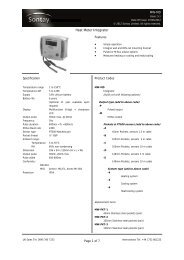
SD-821<br />
Issue: 5.1<br />
Date Of Issue: 25/05/2012<br />
© 2012 <strong>Sontay</strong> Limited. All rights reserved.<br />
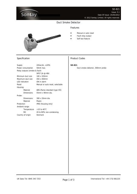
<strong>Duct</strong> <strong>Smoke</strong> <strong>Detector</strong><br />
Features<br />
<br />
<br />
<br />
Manual or auto reset<br />
Fault relay output<br />
Self test feature<br />
Specification<br />
Product Codes<br />
Supply 24Vac/dc, ±20%<br />
Power consumption 50mA max.<br />
Relay outputs (smoke & fault)<br />
SPST 2A @ 48V<br />
Minimum duct size 100 x 320mm<br />
Maximum duct size 450 x 450mm<br />
LED indication ON in alarm<br />
Reset<br />
Manual or auto reset, selectable<br />
Housing:<br />
Material ABS (flame retardant type VO)<br />
Dimensions 55mm x 90mm dia.<br />
Probe:<br />
Dimensions 300 x 20mm dia.<br />
Material Plastic<br />
Protection<br />
IP65 (housing only)<br />
Ambient range:<br />
Temperature +10 to 40°C<br />
RH<br />
20 to 80% non-condensing<br />
Country of origin Denmark<br />
SD-821<br />
<strong>Duct</strong> smoke detector, 300mm probe<br />
UK Sales Tel: 0845 345 7253 International Tel: +44 1732 861225<br />
Page 1 of 3
SD-821<br />
Issue: 5.1<br />
Date Of Issue: 25/05/2012<br />
© 2012 <strong>Sontay</strong> Limited. All rights reserved.<br />
Technical Overview<br />
The SD-821 duct smoke detector operates on the<br />
obscuration principle, using infrared technology and is<br />
designed specifically to cope with the difficult measurement<br />
conditions in air ducts, such as high velocity and levels of<br />
dirt accumulation. The relay output is either auto or manual<br />
reset relay output on detection of smoke.<br />
How It Works<br />
The sensor works by using an infra red transmitter and<br />
receiver fitted to the PCB inside of the housing. The<br />
transmitting device sends a beam, which is reflected from a<br />
mirror in the end of the 300mm long probe, and the<br />
receiving device then receives this beam when there is no<br />
obstacles, like smoke partials in the tube. If smoke is<br />
present, then this will disturb the beam, and the receiver will<br />
loose the signal and an alarm will be activated.<br />
On power up the SD-821 will start an automatic calibration<br />
procedure, the power from the TX device will increase in<br />
small steps, just until the RX device receives enough signal<br />
to validate the “link”. This is stored in the volatile memory<br />
for any further use, or until a new power on. Now any<br />
obstacles, like smoke will force an alarm.<br />
Recommendations<br />
Recommendations (continued)<br />
the position can arise where one duct is feeding smoke and<br />
nine are feeding clean air. The amount of smoke is therefore<br />
diluted by 90%, and if this is coupled with a high flow rate,<br />
the smoke may not be detected for the minimum operating<br />
period of 1 second, resulting in no alarm being generated. It<br />
may be necessary to mount 10 detectors in each of the<br />
small ducts to guarantee correct operation.<br />
Calibration<br />
While the detector is auto-calibrating, the internal LED will<br />
flash red 6 times a second.<br />
When calibration is finished, the LED will change to orange<br />
for a few seconds, the calibration is being stored in the<br />
volatile memory.<br />
The LED will then be continuously lit green, this also<br />
indicates that the sensor is powered correctly and not in<br />
alarm.<br />
Reset Modes<br />
The SD-821 is factory set as manual reset on alarm or fault,<br />
to change modes;<br />
The SD-821 has a probe length of 300mm and should NOT<br />
be used in ducts with a diameter or square size greater than<br />
450mm, as it will not monitor the whole of the duct and<br />
smoke may pass along the duct without being detected.<br />
Units should NOT be mounted where ambient sunlight will<br />
fall on the photocell.<br />
Units should never be mounted at or near sharp bends in<br />
ductwork, as turbulence and side currents can carry the<br />
smoke away from the probe.<br />
The SD-821 is an optical beam detector and therefore, air<br />
velocity has little effect on performance. However, careful<br />
positioning of the detector is required if optimum detection<br />
is to be achieved. The detector should always be fitted with<br />
the holes in the sensing tube parallel to the airflow.<br />
Units should not be mounted close to supply or extract fans.<br />
With large installations, where several ducts collect into a<br />
common duct, consideration must be given to dilution of<br />
smoke and rate of airflow. For example, 10 small ducts may<br />
feed at different points into one large main extract duct, and<br />
if only one smoke detector is fitted in the main extract duct,<br />
Auto reset<br />
Press and hold the PCB mounted button for approx. 5<br />
seconds, the internal LED will change from green to red.<br />
After approx. 5 seconds, the LED will go off for 1 second.<br />
Release the PCB mounted button. The device is now in auto<br />
reset mode, and the LED will be continuously lit green.<br />
Manual reset<br />
Press and hold the PCB mounted button for approx. 5<br />
seconds, the internal LED will change from green to red.<br />
After approx. 5 seconds, the LED will go orange for 1<br />
second. Release the PCB mounted button. The device is now<br />
in manual reset mode, and the LED will be continuously lit<br />
green.<br />
Alarm Condition<br />
If the detector is in alarm or a fault has occurred, the<br />
internal LED will change to red and the external LED will<br />
change to yellow.<br />
Under normal operating conditions the relay is energised.<br />
Therefore, if any fault develops the relay will de-energise<br />
shutting off the equipment connected to the relay, i.e burner<br />
or circulating fan, rendering the installation safe.<br />
UK Sales Tel: 0845 345 7253 International Tel: +44 1732 861225<br />
Page 2 of 3
SD-821<br />
Issue: 5.1<br />
Date Of Issue: 25/05/2012<br />
© 2012 <strong>Sontay</strong> Limited. All rights reserved.<br />
Installation<br />
Connections<br />
1. The SD-821 should only be installed by a competent,<br />
suitably trained technician, experienced in installation<br />
with hazardous voltages.<br />
(>50Vac & 75Vdc & 1500Vdc)<br />
2. Ensure that all power is disconnected before carrying out<br />
any work on the SD-821.<br />
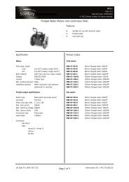
1 2 3 4 5 6<br />
COM NC COM NC +IN GND<br />
3. If the sensor is mounted outside, it is recommended<br />
that the unit be mounted with the cable entry at the<br />
bottom. If the cable is fed from above then into the<br />
cable gland at the bottom, it is recommended that a rain<br />
loop be placed in the cable before entry into the sensor.<br />
RELAY<br />
OUT<br />
FAULT<br />
RELAY<br />
OUT<br />
SMOKE DET.<br />
SUPPLY<br />
IN<br />
24Vac/dc<br />
TEST<br />
4. Drill a 22mm diameter hole, make sure to align the holes<br />
in the probe so that they point into the air flow, not at<br />
right angles to it. Drill two holes at 85mm centres and fix<br />
the IP65 housing to the duct with appropriate screws.<br />
Terminals;<br />
Test & Reset<br />
button<br />
LED<br />
5. Remove the front cover by twisting the lid and<br />
separating from the main body.<br />
6. Feed the cable through the waterproof gland and<br />
terminate the cores at the terminal block. Leaving some<br />
slack inside the unit, tighten the cable gland onto the<br />
cable to ensure water tightness.<br />
7. Maximum cable is 2.5mm², care must be taken not to<br />
over tighten terminals.<br />
1 Fault Output Common<br />
2 Fault Output Normally Closed<br />
3 <strong>Smoke</strong> Detection Output Common<br />
4 <strong>Smoke</strong> Detection Output Normally Closed<br />
5 Supply +24Vac/dc<br />
6 Supply 0V<br />
Manual Reset Button<br />
8. Ensure the supply voltage is within the specified<br />
tolerances.<br />
9. Replace the lid tightly.<br />
Self-Test<br />
The output of the SD-821 can be manually overridden, to<br />
check integrity of the field wiring.<br />
Manual rest button<br />
Press the PCB mounted button for no more than 4 seconds,<br />
otherwise it change the reset mode function. In test mode<br />
both relay outputs will open, the external led will be yellow<br />
and the internal LED red.<br />
Failure Mode<br />
The external LED will flash red if the detector fails.<br />
UK Sales Tel: 0845 345 7253 International Tel: +44 1732 861225<br />
Page 3 of 3<br />
For the latest information and product updates, register at www.sontay.com<br />
Whilst every effort has been made to ensure the accuracy of this specification, <strong>Sontay</strong> cannot accept responsibility for damage, injury, loss or<br />
expense resulting from errors or omissions. In the interest of technical improvement, this specification may be altered without notice.