
You also want an ePaper? Increase the reach of your titles
YUMPU automatically turns print PDFs into web optimized ePapers that Google loves.
SD-821<br />
Issue: 5.1<br />
Date Of Issue: 25/05/2012<br />
© 2012 <strong>Sontay</strong> Limited. All rights reserved.<br />
Technical Overview<br />
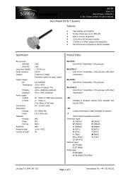
The SD-821 duct smoke detector operates on the<br />
obscuration principle, using infrared technology and is<br />
designed specifically to cope with the difficult measurement<br />
conditions in air ducts, such as high velocity and levels of<br />
dirt accumulation. The relay output is either auto or manual<br />
reset relay output on detection of smoke.<br />
How It Works<br />
The sensor works by using an infra red transmitter and<br />
receiver fitted to the PCB inside of the housing. The<br />
transmitting device sends a beam, which is reflected from a<br />
mirror in the end of the 300mm long probe, and the<br />
receiving device then receives this beam when there is no<br />
obstacles, like smoke partials in the tube. If smoke is<br />
present, then this will disturb the beam, and the receiver will<br />
loose the signal and an alarm will be activated.<br />
On power up the SD-821 will start an automatic calibration<br />
procedure, the power from the TX device will increase in<br />
small steps, just until the RX device receives enough signal<br />
to validate the “link”. This is stored in the volatile memory<br />
for any further use, or until a new power on. Now any<br />
obstacles, like smoke will force an alarm.<br />
Recommendations<br />
Recommendations (continued)<br />
the position can arise where one duct is feeding smoke and<br />
nine are feeding clean air. The amount of smoke is therefore<br />
diluted by 90%, and if this is coupled with a high flow rate,<br />
the smoke may not be detected for the minimum operating<br />
period of 1 second, resulting in no alarm being generated. It<br />
may be necessary to mount 10 detectors in each of the<br />
small ducts to guarantee correct operation.<br />
Calibration<br />
While the detector is auto-calibrating, the internal LED will<br />
flash red 6 times a second.<br />
When calibration is finished, the LED will change to orange<br />
for a few seconds, the calibration is being stored in the<br />
volatile memory.<br />
The LED will then be continuously lit green, this also<br />
indicates that the sensor is powered correctly and not in<br />
alarm.<br />
Reset Modes<br />
The SD-821 is factory set as manual reset on alarm or fault,<br />
to change modes;<br />
The SD-821 has a probe length of 300mm and should NOT<br />
be used in ducts with a diameter or square size greater than<br />
450mm, as it will not monitor the whole of the duct and<br />
smoke may pass along the duct without being detected.<br />
Units should NOT be mounted where ambient sunlight will<br />
fall on the photocell.<br />
Units should never be mounted at or near sharp bends in<br />
ductwork, as turbulence and side currents can carry the<br />
smoke away from the probe.<br />
The SD-821 is an optical beam detector and therefore, air<br />
velocity has little effect on performance. However, careful<br />
positioning of the detector is required if optimum detection<br />
is to be achieved. The detector should always be fitted with<br />
the holes in the sensing tube parallel to the airflow.<br />
Units should not be mounted close to supply or extract fans.<br />
With large installations, where several ducts collect into a<br />
common duct, consideration must be given to dilution of<br />
smoke and rate of airflow. For example, 10 small ducts may<br />
feed at different points into one large main extract duct, and<br />
if only one smoke detector is fitted in the main extract duct,<br />
Auto reset<br />
Press and hold the PCB mounted button for approx. 5<br />
seconds, the internal LED will change from green to red.<br />
After approx. 5 seconds, the LED will go off for 1 second.<br />
Release the PCB mounted button. The device is now in auto<br />
reset mode, and the LED will be continuously lit green.<br />
Manual reset<br />
Press and hold the PCB mounted button for approx. 5<br />
seconds, the internal LED will change from green to red.<br />
After approx. 5 seconds, the LED will go orange for 1<br />
second. Release the PCB mounted button. The device is now<br />
in manual reset mode, and the LED will be continuously lit<br />
green.<br />
Alarm Condition<br />
If the detector is in alarm or a fault has occurred, the<br />
internal LED will change to red and the external LED will<br />
change to yellow.<br />
Under normal operating conditions the relay is energised.<br />
Therefore, if any fault develops the relay will de-energise<br />
shutting off the equipment connected to the relay, i.e burner<br />
or circulating fan, rendering the installation safe.<br />
UK Sales Tel: 0845 345 7253 International Tel: +44 1732 861225<br />
Page 2 of 3