Passive Safety System Response to Postulated Events.pdf - UxC
Passive Safety System Response to Postulated Events.pdf - UxC
Passive Safety System Response to Postulated Events.pdf - UxC

Create successful ePaper yourself
Turn your PDF publications into a flip-book with our unique Google optimized e-Paper software.
Proceedings of ICAPP ‘12<br />
Chicago, USA, June 24-28, 2012<br />
Paper 12157<br />
Westinghouse Small Modular Reac<strong>to</strong>r<br />
<strong>Passive</strong> <strong>Safety</strong> <strong>System</strong> <strong>Response</strong> <strong>to</strong> <strong>Postulated</strong> <strong>Events</strong><br />
Matthew C. Smith<br />
Dr. Richard F. Wright<br />
Westinghouse Electric Company<br />
Westinghouse Electric Company<br />
600 Cranberry Woods Drive, Suite 679 600 Cranberry Woods Drive, Suite 679<br />
Tel: +1 (412) 374-4510 Tel: +1 (412) 374-4719<br />
Email: smithmc@westinghouse.com<br />
Email: wrightrf@westinghouse.com<br />
Abstract – The Westinghouse Small Modular Reac<strong>to</strong>r (SMR) is an 800 MWt (>225 MWe) integral<br />
pressurized water reac<strong>to</strong>r. This paper is part of a series of four describing the design and safety<br />
features of the Westinghouse SMR. This paper focuses in particular upon the passive safety<br />
features and the safety system response of the Westinghouse SMR.<br />
The Westinghouse SMR design incorporates many features <strong>to</strong> minimize the effects of, and in some<br />
cases eliminates the possibility of, postulated accidents. The small size of the reac<strong>to</strong>r and the low<br />
power density limits the potential consequences of an accident relative <strong>to</strong> a large plant. The<br />
integral design eliminates large loop piping, which significantly reduces the flow area of<br />
postulated loss of coolant accidents (LOCAs). The Westinghouse SMR containment is a highpressure,<br />
compact design that normally operates at a partial vacuum. This facilitates heat<br />
removal from the containment during LOCA events. The containment is submerged in water which<br />
also aides the heat removal and provides an additional radionuclide filter.<br />
The Westinghouse SMR safety system design is passive, is based largely on the passive safety<br />
systems used in the AP1000 ® reac<strong>to</strong>r, and provides mitigation of all design basis accidents without<br />
the need for AC electrical power for a period of seven days. Frequent faults, such as reactivity<br />
insertion events and loss of power events, are protected by first shutting down the nuclear reaction<br />
by inserting control rods, then providing cold, borated water through a passive, buoyancy-driven<br />
flow. Decay heat removal is provided using a layered approach that includes the passive removal<br />
of heat by the steam drum and independent passive heat removal system that transfers heat from<br />
the primary system <strong>to</strong> the environment.<br />
Less frequent faults such as loss of coolant accidents are mitigated by passive injection of a large<br />
quantity of water that is readily available inside containment. An au<strong>to</strong>matic depressurization<br />
system is used <strong>to</strong> reduce the reac<strong>to</strong>r pressure in a controlled manner <strong>to</strong> facilitate the passive<br />
injection. Long-term decay heat removal is accomplished using the passive heat removal systems<br />
augmented by heat transfer through the containment vessel <strong>to</strong> the environment. The passive<br />
injection systems are designed so that the fuel remains covered and effectively cooled throughout<br />
the event. Like during the frequent faults, the passive systems provide effective cooling without the<br />
need for ac power for seven days following the accident. Connections are available <strong>to</strong> add<br />
additional water <strong>to</strong> indefinitely cool the plant.<br />
The response of the safety systems of the Westinghouse SMR <strong>to</strong> various initiating faults has been<br />
examined. Among them, two accidents; an extended station blackout event, and a LOCA event<br />
have been evaluated <strong>to</strong> demonstrate how the plant will remain safe in the unlikely event that either<br />
should occur.<br />
AP1000 is a trademark or registered trademark in the United States of Westinghouse Electric Company LLC, its subsidiaries and/or its affiliates. This mark<br />
may be used and/or registered in other countries throughout the world. All rights reserved. Unauthorized use is strictly prohibited. Other names may be<br />
trademarks of their respective owners.<br />
1001
Proceedings of ICAPP ‘12<br />
Chicago, USA, June 24-28, 2012<br />
Paper 12157<br />
I. INTRODUCTION<br />
This paper is the final paper in a series of four papers<br />
designed <strong>to</strong> introduce the design and functionality of the<br />
Westinghouse SMR. This paper focuses on the<br />
functionality of the passive safety systems related <strong>to</strong><br />
postulated events.<br />
The design of the Westinghouse SMR enables<br />
inherently safe power operation while also allowing for a<br />
safe transition from normal operating conditions <strong>to</strong> a<br />
passive shutdown condition. The design includes the three<br />
main barriers of protection of traditional PWRs (fuel<br />
cladding, reac<strong>to</strong>r coolant system (RCS) pressure boundary<br />
and containment) with the added benefit of an external pool<br />
of water <strong>to</strong> filter out radionuclides that might escape from<br />
the containment pressure vessel. Additionally, the plant’s<br />
underground placement reduces the likelihood of external<br />
events affecting the safety of the plant.<br />
The integral design of the RCS contains no large bore<br />
piping, which significantly reduces the flow area of<br />
postulated loss of coolant accidents. The use of control rod<br />
drive mechanisms (CRDMs) internal <strong>to</strong> the pressure<br />
boundary eliminates the possibility that the ejection of a<br />
control rod will occur. The pump driven RCS flow during<br />
power operation results in a large thermal margin of safety<br />
that is predictable <strong>to</strong> a high level of confidence. The<br />
vertical arrangement of the plant allows for a safe transition<br />
<strong>to</strong> natural circulation in the event of a disruption <strong>to</strong> the<br />
forced reac<strong>to</strong>r coolant flow. Also, the vertical arrangement<br />
of the plant inherently places the majority of the RCS water<br />
directly above the core for use in cooling of the reac<strong>to</strong>r<br />
during an event. These design features set the stage for and<br />
augment the passive safety features of the plant.<br />
The Westinghouse SMR is equipped with passive<br />
safety features that draw heavily from the AP1000 plant<br />
design that is certified by the US NRC (Ref. 1).<br />
Specifically, these systems are designed <strong>to</strong> safely shut down<br />
the nuclear reaction, remove decay heat following<br />
shutdown, assure that the reac<strong>to</strong>r core remains covered with<br />
water <strong>to</strong> maintain effective cooling, and provide long-term<br />
cooling and shutdown.<br />
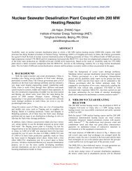
The key components of the passive core cooling<br />
systems are four core makeup tanks (CMTs), an<br />
in-containment pool (ICP) and associated ICP tanks, an<br />
au<strong>to</strong>matic depressurization system (ADS), an outside<br />
containment pool (OCP) and two ultimate heat sink (UHS)<br />
tanks. Integrated in<strong>to</strong> the CMTs are passive residual heat<br />
removal heat exchangers. The Westinghouse SMR reac<strong>to</strong>r<br />
coolant and passive core cooling systems are shown in<br />
Figure 1. Combined, these components provide the<br />
protection required <strong>to</strong> mitigate the various initiating faults<br />
required <strong>to</strong> be examined for PWRs. Among them, two<br />
accidents; an extended station blackout event, and a LOCA<br />
event have been evaluated <strong>to</strong> demonstrate how the plant<br />
will respond in the unlikely event that either should occur.<br />
UHS Tank (1<br />
of 2)<br />
CMT 3<br />
CMT 1<br />
CMT (1 of 4)<br />
RCP (1 of 8)<br />
DVI Line (1<br />
of 4)<br />
CMT Balance<br />
Line (1of 4)<br />
Sump Screen<br />
ICP<br />
IVR<br />
ADS (1 of 4)<br />
SCV<br />
Downcomer<br />
Steam Genera<strong>to</strong>r<br />
CV<br />
RV<br />
Pressurizer<br />
Hot Leg<br />
Steam Genera<strong>to</strong>r<br />
Upper<br />
Plenum<br />
Core<br />
Lower<br />
Plenum<br />
MSIV<br />
MFIV<br />
PORV (x2)<br />
Recirculation<br />
Pump (x2)<br />
Sump Injection<br />
Line (1 of 2)<br />
Outside<br />
Containment<br />
Pool<br />
Fig. 1. Reac<strong>to</strong>r Coolant and <strong>Passive</strong> Core Cooling <strong>System</strong>s<br />
SCV<br />
Sump Screen<br />
IVR<br />
ICP Tank (1 of 2)<br />
ICP<br />
II. REACTOR CONTROL<br />
Steam<br />
Drum<br />
During an event, the Westinghouse SMR relies on the<br />
natural forces of gravity and convection <strong>to</strong> shutdown and<br />
maintains the plant in a safe condition. The protection<br />
system of the Westinghouse SMR will diagnose that reac<strong>to</strong>r<br />
protection is necessary and send a signal <strong>to</strong> de-energize<br />
latches holding the control rods out of the core. A loss of<br />
power <strong>to</strong> these latches will also de-energize them. The<br />
control rods are then free <strong>to</strong> fall by gravity <strong>to</strong> rapidly shut<br />
down the nuclear reaction. In the unlikely event that the<br />
control rods do not fall in<strong>to</strong> the core or an event occurs<br />
while at a shutdown condition, diverse shutdown will be<br />
performed through the gravity-fed injection of highly<br />
borated water from the CMTs. The borated CMT water<br />
also provides long-term reactivity control of the plant. Both<br />
of these short-term and long-term reactivity control<br />
strategies for the Westinghouse SMR are similar <strong>to</strong> those of<br />
the AP1000 plant.<br />
1002
Proceedings of ICAPP ‘12<br />
Chicago, USA, June 24-28, 2012<br />
Paper 12157<br />
III. DECAY HEAT REMOVAL<br />
Like the AP1000 plant, the preferred source of decay<br />
heat removal of the Westinghouse SMR is through the<br />
steam genera<strong>to</strong>r. The unique configuration associated with<br />
the Westinghouse SMR steam genera<strong>to</strong>r tubes with external<br />
steam drum allows for the large water inven<strong>to</strong>ry of the<br />
steam drum <strong>to</strong> be au<strong>to</strong>matically available for decay heat<br />
removal during most accident scenarios but also for<br />
isolation of the steam genera<strong>to</strong>r tubes and containment<br />
from the drum during break scenarios. If available, natural<br />
circulation from the steam drum <strong>to</strong> the steam genera<strong>to</strong>r<br />
tubes and back again <strong>to</strong> the steam drum provides residual<br />
heat removal via steam dump. The capability <strong>to</strong> add<br />
additional inven<strong>to</strong>ry <strong>to</strong> the steam drum and the capability <strong>to</strong><br />
pump flow <strong>to</strong> the steam genera<strong>to</strong>r tubes are also available<br />
should AC power be available. However, neither is<br />
required <strong>to</strong> demonstrate that a safe shutdown condition is<br />
achieved for all design basis scenarios.<br />
Similar <strong>to</strong> the AP1000 plant, the Westinghouse SMR<br />
utilizes a heat exchanger <strong>to</strong> provide safety-grade passive<br />
decay heat removal. In the case of the Westinghouse SMR,<br />
the heat exchanger has been integrated in<strong>to</strong> each of the four<br />
CMTs. The <strong>to</strong>p of each CMT is attached <strong>to</strong> the reac<strong>to</strong>r<br />
coolant system via a balance line pipe connected <strong>to</strong> the<br />
upper internals region of the reac<strong>to</strong>r vessel. The bot<strong>to</strong>m of<br />
each CMT is connected <strong>to</strong> the reac<strong>to</strong>r vessel through direct<br />
vessel injection (DVI) lines in<strong>to</strong> the vessel downcomer.<br />
During normal operation, valves in these lines prevent flow<br />
from circulating through the CMTs. A heat exchanger<br />
within the CMTs allows for heat transfer <strong>to</strong> a secondary<br />
loop of cooling water. As a result of this heat exchanger,<br />
the CMT cooling water is initially much cooler than the<br />
RCS water. Upon opening of the valves, the cold water<br />
falls in<strong>to</strong> the RCS beginning a natural circulation cooling<br />
loop.<br />
The secondary side of each CMT is connected through<br />
a closed loop of piping <strong>to</strong> a heat exchanger that sits in one<br />
of two UHS tanks. The water in the secondary CMT piping<br />
is pressurized <strong>to</strong> ensure liquid water is available <strong>to</strong> remove<br />
heat. Each UHS tank is sized <strong>to</strong> accommodate decay heat<br />
removal from the core and spent fuel pool for at least 72<br />
hours. When combined with the water in the OCP, seven<br />
days of decay heat removal capability is available. The two<br />
UHS tanks are physically separated <strong>to</strong> inhibit an external<br />
event from compromising both tanks. Connections <strong>to</strong> each<br />
UHS tank allow for the addition of water <strong>to</strong> extend the<br />
decay heat removal indefinitely.<br />
The SMR containment is not pressurized during many<br />
frequent fault scenarios.<br />
IV. INVENTORY ADDITION<br />
Along with their role in reac<strong>to</strong>r control and decay heat<br />
removal, the four CMTs of the Westinghouse SMR provide<br />
the first safety-related inven<strong>to</strong>ry addition <strong>to</strong> the RCS. The<br />
CMTs contain a large volume of water that is au<strong>to</strong>matically<br />
delivered <strong>to</strong> the RCS as the water level in the reac<strong>to</strong>r vessel<br />
drops below the CMT balance lines. Additional water,<br />
which is borated and relatively cold, is available in the ICP<br />
tanks for injection <strong>to</strong> the RCS. These two additional<br />
inven<strong>to</strong>ry sources, along with the RCS volume, are<br />
sufficient <strong>to</strong> maintain effective core cooling and provide the<br />
elevation head required <strong>to</strong> transition <strong>to</strong> long-term<br />
recirculation cooling. This strategy is analogous <strong>to</strong> that of<br />
the AP1000 plant which uses two CMTs and an<br />
in-containment refueling water s<strong>to</strong>rage tank (iRWST) for<br />
inven<strong>to</strong>ry addition.<br />
In addition <strong>to</strong> the safety-related methods of inven<strong>to</strong>ry<br />
addition, the chemical and volume control system (if<br />
available) is capable of providing additional make up<br />
water <strong>to</strong> the reac<strong>to</strong>r coolant system should ac power be<br />
available.<br />
V. LONG-TERM COOLING<br />
A vent path for the energy in the RCS <strong>to</strong> the<br />
containment is established by the ADS. As the temperature<br />
in containment rises from the energy exiting the RCS<br />
through the ADS, steam will condense on the relatively<br />
cool inside wall of containment. Heat will be transferred <strong>to</strong><br />
the wall and through the wall <strong>to</strong> the OCP as the<br />
condensation occurs. The condensed water will collect in<br />
the containment sump. With sufficient head, the water in<br />
the sump will overcome the pressure differential in<strong>to</strong> the<br />
reac<strong>to</strong>r vessel and flow will be established. The flow will<br />
pass from the sump through check valves as it enters the<br />
ICP. Once in the ICP, the flow will pass through a screen <strong>to</strong><br />
filter any debris and another check valve just before<br />
entering the reac<strong>to</strong>r vessel. Heat is transferred from the<br />
containment external surface via free convection and<br />
boiling. This process will continue indefinitely as long as<br />
there is water in the OCP.<br />
As the water boils, the level in the pool will drop. Float<br />
valves, which are in lines connecting the OCP <strong>to</strong> the UHS<br />
tanks, will au<strong>to</strong>matically open allowing water from the<br />
UHS <strong>to</strong> refill the OCP. Connections <strong>to</strong> each UHS tank<br />
allow for the addition of water <strong>to</strong> maintain water in the pool<br />
indefinitely. This strategy is much like that of the AP1000<br />
plant in that water condenses on the inside of containment<br />
as a result of the wall being cooled by external water.<br />
1003
Proceedings of ICAPP ‘12<br />
Chicago, USA, June 24-28, 2012<br />
Paper 12157<br />
VI. ACCIDENT SCENARIOS<br />
The passive safety system functions described above<br />
work <strong>to</strong>gether during various initiating faults <strong>to</strong> safely<br />
shutdown the plant. The plant responses <strong>to</strong> an extended<br />
station blackout and a LOCA event have been evaluated;<br />
the sequence of events for each is discussed below. In both<br />
scenarios the fault occurs during normal full power<br />
operation (See Figure 2).<br />
Fig. 3. Initial <strong>Response</strong> <strong>to</strong> Station Blackout<br />
Fig. 2. Normal Full Power Operation<br />
VI.A. Extended Station Blackout<br />
In the unlikely event of an extended station blackout<br />
where both on-site and off-site power is lost, the control<br />
rods drop, as a result of the loss of power, shutting down<br />
bulk power production. The reac<strong>to</strong>r coolant pumps, the<br />
main feedwater pumps and recirculation pumps also lose<br />
power as well and coast down. Natural circulation is<br />
established in the RCS and secondary side of the steam<br />
genera<strong>to</strong>r with the loss of forced flow. Since no additional<br />
inven<strong>to</strong>ry is being added <strong>to</strong> the steam drum, the drum level<br />
begins <strong>to</strong> drop (see Figure 3).<br />
Eventually, the inven<strong>to</strong>ry in the secondary side of the<br />
steam genera<strong>to</strong>r boils off completely. Prior <strong>to</strong> this<br />
occurring, a protection system signal will actuate the valves<br />
below the CMTs. Cold CMT water is then free <strong>to</strong> flow in<strong>to</strong><br />
the RCS. Hot RCS water would enter the CMTs and be<br />
cooled as a result of heat transfer <strong>to</strong> the secondary side.<br />
The CMT heat exchangers receive cooling water via<br />
natural circulation from the above ground UHS tanks. As<br />
heat is added <strong>to</strong> the UHS tanks, temperature begins <strong>to</strong> rise<br />
<strong>to</strong> the boiling point. Each UHS tank is sized <strong>to</strong><br />
accommodate decay heat removal from the core and spent<br />
fuel pool for at least 72 hours. Connections <strong>to</strong> each UHS<br />
tank allow for the heat removal <strong>to</strong> continue indefinitely<br />
(See Figure 4).<br />
Fig. 4. CMT Heat Removal During Station Blackout<br />
1004
Proceedings of ICAPP ‘12<br />
Chicago, USA, June 24-28, 2012<br />
Paper 12157<br />
VI.B. Loss of Coolant Accident<br />
In the unlikely event of a loss of coolant accident (e.g.,<br />
DVI line break), the RCS inven<strong>to</strong>ry decreases and as a<br />
result the RCS pressure and pressurizer water level<br />
decrease. As pressure drops, the pressurizer heaters will<br />
actuate in an attempt <strong>to</strong> maintain pressure. Water level and<br />
pressure continue <strong>to</strong> drop until a protection system setpoint<br />
is reached. Upon expiration of applicable delays, the rods<br />
enter the core significantly reducing the heat generated.<br />
Shortly after reac<strong>to</strong>r trip, redundant isolation valves<br />
between the steam genera<strong>to</strong>r tubes and the steam drum are<br />
closed and a protection system signal would be generated<br />
<strong>to</strong> open the valve below the four CMTs.<br />
then drains cooling water <strong>to</strong> the reac<strong>to</strong>r vessel (See<br />
Figure 6).<br />
With the CMT valves open, the relatively cold, highly<br />
borated CMT water would flow in<strong>to</strong> the RCS. Hot RCS<br />
water would enter the CMT and be cooled as a result of<br />
heat transfer <strong>to</strong> the secondary side. The CMT heat<br />
exchanger receives cooling water via natural circulation<br />
from the above ground UHS tank.<br />
Some of the RCS inven<strong>to</strong>ry provided by the break <strong>to</strong><br />
containment will condense; the condensate will collect at<br />
the bot<strong>to</strong>m of containment. As the pressure in containment<br />
increases, a disk in the ICP tank will rupture <strong>to</strong> equalize the<br />
ICP and containment pressures (See Figure 5).<br />
Fig. 6. CMT Natural Circulation / Draining<br />
As the CMT drains, a protection system signal is<br />
generated <strong>to</strong> open the au<strong>to</strong>matic depressurization system<br />
(ADS) valves which are attached <strong>to</strong> lines off of the CMT.<br />
Valves at the <strong>to</strong>p of the ICP tanks and in<strong>to</strong> the reac<strong>to</strong>r<br />
vessel also open on the same signal. The opening of the<br />
ADS valves allows the RCS <strong>to</strong> equalize with the<br />
containment. As the pressures approach equilibrium, the<br />
head in the ICP tanks is high enough <strong>to</strong> allow injection<br />
through check valves in<strong>to</strong> the reac<strong>to</strong>r vessel (See Figure 7).<br />
Fig. 5. LOCA Blowdown<br />
As additional inven<strong>to</strong>ry is released <strong>to</strong> containment and<br />
CMT heat transfer occurs, the water in the UHS tanks and<br />
the OCP begins <strong>to</strong> boil. As RCS water level reaches the<br />
elevation of the CMT balance lines, steam enters the lines<br />
and breaks the natural circulation of liquid water. The CMT<br />
Fig. 7. ADS Actuation / ICP Tank Injection<br />
1005
Proceedings of ICAPP ‘12<br />
Chicago, USA, June 24-28, 2012<br />
Paper 12157<br />
With the ICP tanks and CMTs drained, the water level<br />
in the containment sump will be high enough <strong>to</strong> overcome<br />
the pressure differential in<strong>to</strong> the reac<strong>to</strong>r vessel and flow<br />
will be established. The water heated <strong>to</strong> steam by the core<br />
will exit the reac<strong>to</strong>r vessel through the vent path established<br />
through the ADS valves. Some steam will also condense in<br />
the CMT heat exchanger tubes and return <strong>to</strong> the reac<strong>to</strong>r<br />
vessel. Outside of the reac<strong>to</strong>r vessel, the steam will<br />
continue <strong>to</strong> condense on the containment wall with the<br />
condensate returning <strong>to</strong> the sump. This process will<br />
continue indefinitely as long as there is water in the OCP.<br />
The OCP will continue <strong>to</strong> boil, as it does, the water<br />
level will drop until the float valves in the lines connecting<br />
the OCP <strong>to</strong> the UHS tanks au<strong>to</strong>matically open. Once<br />
opened, water from the UHS will refill the OCP. Each<br />
UHS tank is sized <strong>to</strong> accommodate decay heat removal<br />
from the core and spent fuel pool for at least 72 hours.<br />
Connections <strong>to</strong> each UHS tank allow for the addition of<br />
water <strong>to</strong> maintain water in the pool indefinitely (See Figure<br />
8).<br />
TABLE I<br />
Comparison of Functions<br />
Function AP1000 Westinghouse SMR<br />
Short Term Control Rods Control Rods<br />
Reactivity Controls<br />
Long-Term 2 CMTs 4 CMTs<br />
Reactivity Controls<br />
Decay Heat<br />
Removal<br />
1 PRHR / PCS 4 CMTs w/ integral<br />
heat exchangers<br />
Long-Term Makeup 1 iRWST / Sump 2 ICP Tanks / Sump<br />
Water Supply<br />
Ultimate Heat Sink PCS (72 hours) 2 UHS Tanks<br />
(72 hours each)<br />
ACKNOWLEDGMENTS<br />
The authors would like <strong>to</strong> thank Ed Cummins,<br />
Stephanie Harsche and the SMR design team for their<br />
support.<br />
ACRONYMS<br />
ADS<br />
CMT<br />
CRDM<br />
DVI<br />
ICP<br />
iRWST<br />
LOCA<br />
OCP<br />
PCS<br />
PWR<br />
RCS<br />
SMR<br />
UHS<br />
Au<strong>to</strong>matic Depressurization <strong>System</strong><br />
Core Makeup Tank<br />
Control Rod Drive Mechanism<br />
Direct Vessel Injection<br />
In-Containment Pool<br />
In-Containment Refueling Water S<strong>to</strong>rage Tank<br />
Loss of Coolant Accident<br />
Outside Containment Pool<br />
<strong>Passive</strong> Containment Cooling <strong>System</strong><br />
Pressurized Water Reac<strong>to</strong>r<br />
Reac<strong>to</strong>r Coolant <strong>System</strong><br />
Small Modular Reac<strong>to</strong>r<br />
Ultimate Heat Sink<br />
Fig. 8. Long-Term Core Cooling<br />
Preliminary analysis results of a LOCA event for the<br />
Westinghouse SMR are described in detail in Ref. 2.<br />
VII. CONCLUSIONS<br />
The Westinghouse SMR is taking the passive safety<br />
principles of the AP1000 plant <strong>to</strong> the next level of safety<br />
(See Table I). As described, the systems safely shut down<br />
the nuclear reaction, remove decay heat following<br />
shutdown, assure that the reac<strong>to</strong>r core remains covered with<br />
water <strong>to</strong> maintain effective cooling and provide long-term<br />
cooling and shutdown during LOCA and Station Blackout<br />
events.<br />
REFERENCES<br />
1. ML113560390, “Federal Register Notice - AP1000<br />
Design Certification Amendment, 10 CFR Part 52<br />
(RIN 3150-AI81) NRC-2010-0131,” 12/22/2011.<br />
2. J. Liao, V. N. Kucukboyaci, L. Nguyen and C. Frepoli,<br />
“Preliminary LOCA Analysis of the Westinghouse<br />
Small Modular Reac<strong>to</strong>r Using the WCOBRA/TRAC-<br />
TF2 Thermal Hydraulics Code,” Proc. of ICAPP’12,<br />
Chicago, U.S.A. (2012)<br />
1006