EFIS-D6 Pilot's User - Dynon Avionics
EFIS-D6 Pilot's User - Dynon Avionics
EFIS-D6 Pilot's User - Dynon Avionics

Create successful ePaper yourself
Turn your PDF publications into a flip-book with our unique Google optimized e-Paper software.
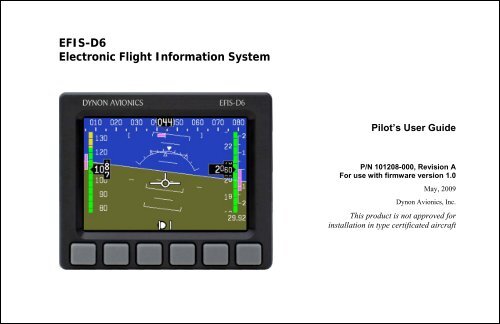
<strong>EFIS</strong>-<strong>D6</strong><br />
Electronic Flight Information System<br />
Pilot’s <strong>User</strong> Guide<br />
P/N 101208-000, Revision A<br />
For use with firmware version 1.0<br />
May, 2009<br />
<strong>Dynon</strong> <strong>Avionics</strong>, Inc.<br />
This product is not approved for<br />
installation in type certificated aircraft
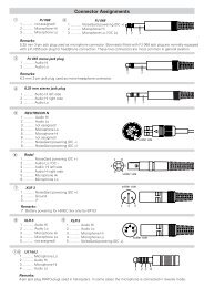
Contact Information<br />
<strong>Dynon</strong> <strong>Avionics</strong>, Inc.<br />
19825 141 st Place NE<br />
Woodinville, WA 98072<br />
Phone: (425) 402-0433 - 7:00 AM – 5:00 PM (Pacific Time) Monday - Friday<br />
Fax: (425) 984-1751<br />
<strong>Dynon</strong> <strong>Avionics</strong> offers online sales, extensive support, and continually-updated information on its products via its Internet sites:<br />
• www.dynonavionics.com –<strong>Dynon</strong> <strong>Avionics</strong> primary web site; including:<br />
• docs.dynonavionics.com – Current and archival documentation.<br />
• downloads.dynonavionics.com – Software downloads.<br />
• support.dynonavionics.com – Support resources.<br />
• store.dynonavionics.com – <strong>Dynon</strong>’s secure online store for purchasing all <strong>Dynon</strong> products 24 hours a day.<br />
• wiki.dynonavionics.com – <strong>Dynon</strong> <strong>Avionics</strong>’ Documentation Wiki provides enhanced, extended, continuously-updated online documentation<br />
contributed by <strong>Dynon</strong> employees and customers.<br />
• forum.dynonavionics.com – <strong>Dynon</strong> <strong>Avionics</strong>’ Internet forum where <strong>Dynon</strong> customers can interact and receive <strong>Dynon</strong> technical support<br />
outside of telephone support hours. A key feature of the forum is that it allows the exchange of diagrams, photos, and other types of files.<br />
• newsletter.dynonavionics.com – <strong>Dynon</strong>’s email newsletter.<br />
• blog.dynonavionics.com – <strong>Dynon</strong>’s blog where you can find new and interesting <strong>Dynon</strong>-related content.<br />
Copyright<br />
© 2003-2009 <strong>Dynon</strong> <strong>Avionics</strong>, Inc. All rights reserved. No part of this manual may be reproduced, copied, transmitted, disseminated or stored in any<br />
storage medium, for any purpose without the express written permission of <strong>Dynon</strong> <strong>Avionics</strong>. <strong>Dynon</strong> <strong>Avionics</strong> hereby grants permission to download a<br />
single copy of this manual and of any revision to this manual onto a hard drive or other electronic storage medium to be viewed for personal use,<br />
provided that such electronic or printed copy of this manual or revision must contain the complete text of this copyright notice and provided further<br />
that any unauthorized commercial distribution of this manual or any revision hereto is strictly prohibited.<br />
Information in this document is subject to change without notice. <strong>Dynon</strong> <strong>Avionics</strong> reserves the right to change or improve its products and to make<br />
changes in the content without obligation to notify any person or organization of such changes. Visit the <strong>Dynon</strong> <strong>Avionics</strong> website
(www.dynonavionics.com) for current updates and supplemental information concerning the use and operation of this and other <strong>Dynon</strong> <strong>Avionics</strong><br />
products.<br />
Limited Warranty<br />
<strong>Dynon</strong> <strong>Avionics</strong> warrants this product to be free from defects in materials and workmanship for three years from date of shipment. <strong>Dynon</strong> <strong>Avionics</strong><br />
will, at its sole option, repair or replace any components that fail in normal use. Such repairs or replacement will be made at no charge to the customer<br />
for parts or labor. The customer is, however, responsible for any transportation cost. This warranty does not cover failures due to abuse, misuse,<br />
accident, improper installation or unauthorized alteration or repairs.<br />
THE WARRANTIES AND REMEDIES CONTAINED HEREIN ARE EXCLUSIVE, AND IN LIEU OF ALL OTHER WARRANTIES<br />
EXPRESSED OR IMPLIED, INCLUDING ANY LIABILITY ARISING UNDER WARRANTY OF MERCHANTABILITY OR FITNESS FOR A<br />
PARTICULAR PURPOSE, STATUTORY OR OTHERWISE. THIS WARRANTY GIVES YOU SPECIFIC LEGAL RIGHTS, WHICH MAY<br />
VARY FROM STATE TO STATE.<br />
IN NO EVENT SHALL DYNON AVIONICS BE LIABLE FOR ANY INCIDENTAL, SPECIAL, INDIRECT OR CONSEQUENTIAL DAMAGES,<br />
WHETHER RESULTING FROM THE USE, MISUSE OR INABILITY TO USE THIS PRODUCT OR FROM DEFECTS IN THE PRODUCT.<br />
SOME STATES DO NOT ALLOW THE EXCLUSION OF INCIDENTAL OR CONSEQUENTIAL DAMAGES, SO THE ABOVE LIMITATIONS<br />
MAY NOT APPLY TO YOU.<br />
<strong>Dynon</strong> <strong>Avionics</strong> retains the exclusive right to repair or replace the instrument or firmware or offer a full refund of the purchase price at its sole<br />
discretion. SUCH REMEDY SHALL BE YOUR SOLE AND EXCLUSIVE REMEDY FOR ANY BREACH OF WARRANTY.<br />
These instruments are not intended for use in type certificated aircraft at this time. <strong>Dynon</strong> <strong>Avionics</strong> makes no claim as to the suitability of its products<br />
in connection with FAR 91.205.<br />
<strong>Dynon</strong> <strong>Avionics</strong>’ products incorporate a variety of precise, calibrated electronics. Except for replacing the optional internal backup battery in <strong>EFIS</strong>based<br />
products per the installation guide, our products do not contain any field/user-serviceable parts. Units that have been found to have been taken<br />
apart may not be eligible for repair under warranty. Additionally, once a <strong>Dynon</strong> <strong>Avionics</strong> unit is opened up, it will require calibration and verification<br />
at our Woodinville, WA offices before it can be considered airworthy.<br />
<strong>EFIS</strong>-<strong>D6</strong> Pilot’s <strong>User</strong> Guide<br />
iii
Table of Contents<br />
Contact Information..............................................................................................................................................................ii<br />
Copyright..............................................................................................................................................................................ii<br />
Limited Warranty ................................................................................................................................................................iii<br />
1. Introduction 1-1<br />
Before You Fly..................................................................................................................................................................1-1<br />
Warning .............................................................................................................................................................................1-1<br />
About this Guide................................................................................................................................................................1-1<br />
2. Product Overview 2-1<br />
<strong>EFIS</strong>-<strong>D6</strong> Hardware............................................................................................................................................................2-1<br />
ADAHRS Operation..........................................................................................................................................................2-2<br />
3. Product Operation 3-1<br />
Front Panel Layout ............................................................................................................................................................3-1<br />
Display...............................................................................................................................................................................3-2<br />
Menus ................................................................................................................................................................................3-2<br />
4. Display Elements 4-1<br />
Horizon line, pitch and roll indicators ...............................................................................................................................4-1<br />
Stabilized heading tape and digital readout .......................................................................................................................4-2<br />
Turn rate indicator .............................................................................................................................................................4-2<br />
Altitude tape, digital readout, and VSI ..............................................................................................................................4-3<br />
Angle of attack (AOA) indicator .......................................................................................................................................4-3<br />
<strong>EFIS</strong>-<strong>D6</strong> Pilot’s <strong>User</strong> Guide<br />
v
Table of Contents<br />
Airspeed tape, digital readout, and trend .......................................................................................................................... 4-4<br />
Slip/skid ball ..................................................................................................................................................................... 4-5<br />
Altimeter setting display................................................................................................................................................... 4-5<br />
5. Operation 5-1<br />
POWER – Power on/off ................................................................................................................................................... 5-1<br />
BARO – Changing Altimeter Setting ............................................................................................................................... 5-1<br />
SETUP – Setting Preferences ........................................................................................................................................... 5-2<br />
6. Alerts 6-1<br />
Alarm Indicators ............................................................................................................................................................... 6-1<br />
7. Appendix 7-1<br />
Appendix A: PC Support Program ................................................................................................................................... 7-1<br />
Appendix B: Troubleshooting .......................................................................................................................................... 7-1<br />
Appendix C: <strong>EFIS</strong>-<strong>D6</strong> Specifications............................................................................................................................... 7-5<br />
vi<br />
<strong>EFIS</strong>-<strong>D6</strong> Pilot’s <strong>User</strong> Guide
1. INTRODUCTION<br />
Thank you for purchasing the <strong>Dynon</strong> <strong>Avionics</strong> <strong>EFIS</strong>-<strong>D6</strong>. This section provides some important cautionary information<br />
and general usage instructions for this manual.<br />
Before You Fly<br />
We strongly recommended that you read this entire guide before attempting to use the <strong>EFIS</strong>-<strong>D6</strong> in an actual flying<br />
situation. Additionally, we encourage you to spend time on the ground familiarizing yourself with the operation of the<br />
product. While first learning to use the instrument in the air, we recommend you have a backup pilot with you in the<br />
aircraft. Finally, we encourage you to keep this manual in the aircraft with you at all times. This document is designed to<br />
give you quick access to information that might be needed in flight. CAUTION: in a flying situation, it is the pilot’s<br />
responsibility to use the product and the guide prudently.<br />
Warning<br />
<strong>Dynon</strong> <strong>Avionics</strong>’ products incorporate a variety of precise, calibrated electronics. Except for replacing the optional<br />
internal backup battery in <strong>EFIS</strong>-based products per the installation guide, our products do not contain any field/userserviceable<br />
parts. Units that have been found to have been taken apart may not be eligible for repair under warranty.<br />
Additionally, once a <strong>Dynon</strong> <strong>Avionics</strong> unit is opened up, it will require calibration and verification at our Woodinville,<br />
WA offices before it can be considered airworthy.<br />
About this Guide<br />
This guide serves two purposes. The first is to help you configure and get acquainted with the <strong>EFIS</strong>-<strong>D6</strong>’s many<br />
functions. The second is to give you quick access to vital information. For detailed technical and installation information,<br />
please refer to the <strong>EFIS</strong>-<strong>D6</strong> Installation Guide.<br />
<strong>EFIS</strong>-<strong>D6</strong> Pilot’s <strong>User</strong> Guide 1-1
Introduction<br />
In the electronic (.PDF) version of this manual, page and section references in the Table of Contents and elsewhere act as<br />
hyperlinks taking you to the relevant location in the manual. The latest version of this manual may be downloaded from<br />
our website at docs.dynonavionics.com.<br />
This guide discusses the most common operation scenarios. If you have an operational issue that is not discussed in this<br />
guide, you can find additional operational information on <strong>Dynon</strong>’s Internet sites:<br />
• wiki.dynonavionics.com – <strong>Dynon</strong>’s Documentation Wiki provides enhanced, extended, frequently updated online<br />
documentation contributed by <strong>Dynon</strong> employees and customers.<br />
• forum.dynonavionics.com – <strong>Dynon</strong>’s Online Customer Forum is a resource for <strong>Dynon</strong> <strong>Avionics</strong> customers to<br />
discuss installation and operational issues relating to <strong>Dynon</strong> <strong>Avionics</strong> products. The Forum is especially useful for<br />
pilots with uncommon aircraft or unusual installation issues. For customers that cannot call <strong>Dynon</strong> Technical<br />
Support during our normal business hours, the Forum is a convenient way to interact with <strong>Dynon</strong> <strong>Avionics</strong><br />
Technical Support. The Forum allows online sharing of wiring diagrams, photos, and other types of electronic files.<br />
Any text following this icon refers to a setting or situation which merits particularly close attention.<br />
1-2 <strong>EFIS</strong>-<strong>D6</strong> Pilot’s <strong>User</strong> Guide
2. PRODUCT OVERVIEW<br />
This section provides a general overview of the various parts of the <strong>EFIS</strong>-<strong>D6</strong> as well as a theory of operation. The<br />
information in this section serves as a reference only and helps familiarize you with the inner workings of the unit. It<br />
should not be used for diagnostic or reparative work.<br />
<strong>EFIS</strong>-<strong>D6</strong> Hardware<br />
The <strong>EFIS</strong>-<strong>D6</strong> uses solid-state sensors to provide accurate and reliable information about your flying environment in an<br />
easy-to-use interface.<br />
POWER<br />
The <strong>EFIS</strong>-<strong>D6</strong> requires between 10 and 30 volts DC for operation. It is acceptable to have the <strong>EFIS</strong>-<strong>D6</strong> turned on during<br />
engine start.<br />
The <strong>EFIS</strong>-<strong>D6</strong> can be ordered with an optional internal battery which allows the instrument to continue to operate in the<br />
event of an external power failure. This lithium-ion battery is rechargeable and is managed by the <strong>EFIS</strong>-<strong>D6</strong>. Under<br />
normal conditions, the internal battery should have a voltage between 13 and 16.8 volts. When the battery’s voltage<br />
drops below 13 volts, the <strong>EFIS</strong>-<strong>D6</strong> displays a low battery warning. When new, a fully charged internal battery is rated<br />
for a minimum of 2 hours of normal operation with the <strong>EFIS</strong>-<strong>D6</strong>. If the <strong>EFIS</strong>-<strong>D6</strong> has switched to its internal emergency<br />
battery due to a power loss in your aircraft, it is advised that you land as soon as possible.<br />
SENSORS AND INPUTS<br />
Attitude information is obtained from 3 solid-state gyrometers, 3 solid-state accelerometers, and the airspeed pressure<br />
sensor. Heading information is obtained from 3 solid-state magnetometers housed in the EDC-D10A. Airspeed, altitude<br />
and angle of attack are obtained from three separate pressure transducers.<br />
<strong>EFIS</strong>-<strong>D6</strong> Pilot’s <strong>User</strong> Guide 2-1
Product Overview<br />
OUTPUTS<br />
The <strong>EFIS</strong>-<strong>D6</strong> has an output to drive an external customer-supplied audible device for AOA (if installed) and altitude<br />
alerts.<br />
A serial output is also provided for serial altitude encoder data. An optional Serial-to-Gray Code Converter is available<br />
for connection to Mode C Gray Code transponders.<br />
DISPLAY<br />
The display is a 4-inch, 320 by 240 pixel, 450-nit LCD screen.<br />
BUTTONS AND KNOBS<br />
<strong>User</strong> interaction takes place via the six buttons along the bottom of the front panel of the unit.<br />
ADAHRS Operation<br />
The primary flight instruments on your <strong>EFIS</strong> display are generated using a group of calibrated sensors. All of them are<br />
solid state – that is, there are no moving parts. These sensors include accelerometers, which measure forces in all three<br />
directions; rotational rate sensors, which sense rotation about all three axes; pressure transducers for measuring air data;<br />
and magnetometers on all three axes for measuring magnetic heading. These sensors form the core of <strong>Dynon</strong>’s Air Data<br />
Attitude and Heading Reference System (ADAHRS).<br />
The table below describes which inputs and sensors are used within the <strong>EFIS</strong> to generate the different displayed<br />
instruments. It is not meant to enable in-flight troubleshooting, but is provided to convey how much of an integrated<br />
system your <strong>EFIS</strong> is.<br />
2-2 <strong>EFIS</strong>-<strong>D6</strong> Pilot’s <strong>User</strong> Guide
Product Overview<br />
GPS Pitot Static AOA Magnetometers Rate Sensors Accelerometers<br />
Ball<br />
X<br />
Altitude<br />
X<br />
Airspeed X X<br />
AOA X X X<br />
Turn Rate X* X X X X<br />
Heading X* X X X X X<br />
Attitude X* X X X X<br />
ATTITUDE CALCULATION<br />
The <strong>EFIS</strong>-<strong>D6</strong> artificial horizon display (attitude) is generated via a complex algorithm using a multitude of<br />
sensors. Your <strong>EFIS</strong> attitude is not reliant on any single external system. It can provide an accurate attitude -<br />
even in the event of airspeed loss (due to icing or other blockage) - via a redundant GPS aiding source. In<br />
normal operation the instrument uses airspeed to provide superior attitude accuracy. If a problem<br />
develops with your airspeed reading, a properly connected and configured GPS source acts as a<br />
substitute. When in this mode the instrument continues to provide accurate attitude.<br />
*If a GPS is present upon the loss of airspeed, the <strong>EFIS</strong>-<strong>D6</strong> uses the GPS ground speed in its attitude calculation. When<br />
in this mode, a magenta GPS ASSIST message is displayed over the horizon and the ground speed is displayed below the<br />
IAS indicator (as shown at right). If the connectivity with the GPS fails while in GPS assist<br />
mode, the attitude continues to be displayed, using the last known GPS ground speed as a<br />
reference. This mode is flagged on the horizon with a yellow CROSS CHECK ATTITUDE<br />
message. In the very rare case that this sequence of event occurs, the <strong>EFIS</strong>-<strong>D6</strong>’s attitude<br />
accuracy is reduced; use other references in the aircraft to cross-check against the <strong>EFIS</strong>-<strong>D6</strong>’s<br />
attitude.<br />
<strong>EFIS</strong>-<strong>D6</strong> Pilot’s <strong>User</strong> Guide 2-3
3. PRODUCT OPERATION<br />
After reading this section, you will be familiar with the basics of how to use your <strong>EFIS</strong>-<strong>D6</strong>. For details regarding specific<br />
procedures (e.g., adjusting display brightness, changing the altimeter setting, etc.) please refer to the Operation section.<br />
Front Panel Layout<br />
All normal operation of the <strong>EFIS</strong>-<strong>D6</strong> happens via the front panel. The<br />
front panel contains buttons and a display.<br />
• Buttons – There are six buttons on the front panel of the <strong>EFIS</strong>-<br />
<strong>D6</strong>. Throughout this guide, these buttons are referred to as one<br />
through six, with button one being the leftmost and button six<br />
being the rightmost. <strong>EFIS</strong>-<strong>D6</strong> buttons are used to turn the<br />
instrument on and off, scroll through menus, and adjust<br />
instrument parameters.<br />
• Display – The display shows <strong>EFIS</strong> information and menus.<br />
1 2 3 4 5 6<br />
<strong>User</strong> interaction takes place via the <strong>EFIS</strong>-<strong>D6</strong><br />
main display and the six buttons beneath.<br />
<strong>EFIS</strong>-<strong>D6</strong> Pilot’s <strong>User</strong> Guide 3-1
Product Operation<br />
Display<br />
The <strong>EFIS</strong>-<strong>D6</strong> display is the most obvious and commonly used output of the device.<br />
Menus<br />
All interaction with the <strong>EFIS</strong>-<strong>D6</strong> is accomplished through the use of its menu system. The menu system is accessed and<br />
navigated via the six buttons located on the front of the unit. With no menu displayed, press any button to display the<br />
main menu. With a menu displayed, pressing any one of these buttons performs the action – or enters the menu –<br />
described by the label above it.<br />
FUNCTIONALITY<br />
A menu consists of two rows of gray boxes containing text. The upper row contains one tab that denotes the currently<br />
displayed menu. The lower row contains six labels that denote the function of the button below it. Many of the onscreen<br />
elements move up to avoid the menu. This prevents the menu from obscuring useful data while it is up. Upon exiting the<br />
menu, the screen returns to its normal appearance.<br />
Pressing a button either displays another menu or adjusts a parameter. If there is no text above a button, then that button<br />
does not have a function in the context of that menu. Occasionally, a button label spans two or more buttons. In this case,<br />
any button below the label invokes the command.<br />
If a menu contains more options than there are buttons, the MORE label is displayed over button five. Pressing this<br />
button shows you the next set of options in the current menu.<br />
In any menu, press the BACK button to return to the previous menu and save any changes. In all top-level menus, button<br />
six is the EXIT button. Pressing EXIT removes the menu system and moves many of the onscreen elements down to<br />
their original positions.<br />
3-2 <strong>EFIS</strong>-<strong>D6</strong> Pilot’s <strong>User</strong> Guide
FLOW<br />
Each page has its own main menu, which may contain options for<br />
navigating to other menus or choosing and adjusting parameters. For<br />
example, the <strong>EFIS</strong> SETUP menu contains button labels for PITCH,<br />
UNITS, CLUTTR, MORE, and BACK. Pressing MORE reveals the rest<br />
of the SETUP menu. That menu contains options for VRSION, IASCLR,<br />
ALTENC, BARO, MORE, and BACK. Pressing MORE on the last menu<br />
of the series simply returns you to the first part of the <strong>EFIS</strong> menu.<br />
To exit the menu system, press the BACK button as many times as is<br />
needed to reach an EXIT button. This varies based upon how deep you<br />
are into the menu system.<br />
DESCRIPTIONS IN THIS GUIDE<br />
Product Operation<br />
Each menu consists of labels above each<br />
button denoting their function.<br />
Throughout this guide, the “>” character is used to indicate entering a deeper level of the menu system. For example,<br />
“SETUP > BARO” indicates entering the SETUP menu, pressing MORE, and then pressing BARO. Note that the<br />
MORE button is not included in the sequence, since pressing MORE reveals more options in the same level of the menu<br />
system.<br />
<strong>EFIS</strong>-<strong>D6</strong> Pilot’s <strong>User</strong> Guide 3-3
4. DISPLAY ELEMENTS<br />
The <strong>EFIS</strong> main pages use various tapes, digital displays, and other<br />
indicators overlaid on an artificial horizon.<br />
Some of the displayed items described below may not be onscreen,<br />
depending on whether or not they have been enabled in the SETUP ><br />
CLUTTR menu.<br />
The following sections provide detail on each onscreen display<br />
element.<br />
Horizon line, pitch and roll indicators<br />
Bounded on the top by blue, and on the bottom by brown, the horizon<br />
line behaves in much the same way as a traditional gyro-based artificial horizon. Unlike a<br />
mechanical artificial horizon, the <strong>EFIS</strong>-<strong>D6</strong>’s horizon has no roll or pitch limitation. The horizon<br />
line stays parallel to the Earth’s horizon line regardless of attitude. The parallel lines above and<br />
below the horizon line are the pitch indicator lines, with each line indicating 5 degrees of pitch.<br />
The end of each 10º pitch indicator line has a hooked barb that points towards the horizon line to<br />
aid attitude awareness.<br />
The roll scale has tic marks at 10, 20, 30, 45, 60, and 90 degrees of roll. In the CLUTTR menu<br />
(described on page 5-3), you can choose between a stationary roll indicator and one that rotates<br />
along with the horizon. The stationary roll indicator (type 1 in the SETUP > CLUTTR > ROLL menu) has an internal<br />
arrow which moves to stay perpendicular to the horizon, like a jet <strong>EFIS</strong> presentation. The moving roll indicator (type 2)<br />
rotates the scale about a stationary internal arrow which points to the current roll angle on the scale, like most<br />
mechanical attitude instrument presentations.<br />
<strong>EFIS</strong>-<strong>D6</strong> Pilot’s <strong>User</strong> Guide 4-1
Display Elements<br />
Stabilized heading tape and digital readout<br />
Located at the top of the <strong>EFIS</strong> page, the heading indicator<br />
functions much like a standard slaved directional gyro.<br />
North, East, South, and West directions are labeled on the tape, “N,” “E,” “S,” and “W,” respectively. The digital readout<br />
displays your current heading, while the surrounding tape scrolls beneath its arrow.<br />
Like a conventional gyro-stabilized magnetic compass, magnetic heading reacts immediately to turn rate so that heading<br />
changes are reflected immediately. It then uses magnetometer data over the long term to ensure that it remains correct.<br />
Additionally, heading is corrected for attitude so that it is accurate as you pitch and roll.<br />
Turn rate indicator<br />
Centered just below the heading digital readout, the turn rate indicator displays the<br />
aircraft’s current rate of turn with respect to the ground. The magenta bar grows in<br />
the direction that the aircraft is currently turning, and is anchored at a white<br />
vertical anchor line. The brackets on either side of the bar’s anchor line represent<br />
the turn rate which results in a standard rate turn. Turn rate takes attitude into<br />
account. This means that even when you are highly banked, it still shows rate of turn in relation to the aircraft’s heading.<br />
The turn rate indicator is scaled to indicate a 6-second heading trend. In the example above, the trend indicator is<br />
showing that the aircraft will be pointed at 40º in 6 seconds if the rate of turn does not change.<br />
4-2 <strong>EFIS</strong>-<strong>D6</strong> Pilot’s <strong>User</strong> Guide
Display Elements<br />
Altitude tape, digital readout, and VSI<br />
The altitude tape scrolls beneath the altitude digital readout and arrow. The digital readout’s digits scroll<br />
up and down, simulating an analog altimeter and giving a sense of the direction of movement. Thousands<br />
of feet are displayed using large numbers while hundreds of feet are displayed in smaller numbers. The<br />
<strong>EFIS</strong>-<strong>D6</strong> accurately displays altitudes from -1200 to 30,000 ft (-365 to 9144 m).<br />
The graphical Vertical Speed Indicator is located next to the altitude tape. The magenta bar grows in the<br />
direction of – and in proportion to – the rate of climb or descent. The numbers on the scale represent<br />
thousands of feet per minute. In the CLUTTR menu, the VSI scale can be set to display 1000 ft/min, 2000<br />
ft/min, and 4000 ft/min. The 2000 ft/min scale is linear throughout the range, while the 1000 ft/min and<br />
4000 ft/min are non-linear as shown on the scale. When set to display 2000 ft/min, the VSI bar is scaled to<br />
indicate a 6-second altitude trend based on its position with relation to the altitude bar. When set to display<br />
4000 ft/min, the VSI bar is scaled to indicate a 6-second trend only up to 1000 ft/min. When set to display<br />
1000 ft/min, the VSI bar is scaled to indicate a 12-second trend up to 500 ft/min.<br />
During the first 30 seconds of operation, the altitude tape and digital readout are not displayed as the unit<br />
needs a small amount of time before altitude measurements are deemed accurate.<br />
Angle of attack (AOA) indicator<br />
The angle of attack indicator – available only with <strong>Dynon</strong>’s AOA Pitot Probe – displays the aircraft’s current<br />
AOA relative to the stall AOA. The AOA calibration process should result in the lowest angle of attack stall<br />
(usually the “clean” configuration) occurring between the yellow and red lines and the higher angle-of-attack stall<br />
(usually the “dirty” configuration) occurring at the top of the red. As your aircraft’s angle of attack increases, the<br />
bars in the indicator disappear, leaving the empty outline. As your aircraft’s AOA approaches stall, downwardpointing<br />
arrows are left. Depending on your installation and configuration, an audible alarm may also occur when<br />
<strong>EFIS</strong>-<strong>D6</strong> Pilot’s <strong>User</strong> Guide 4-3
Display Elements<br />
near or in the stall. This audio alarm is accompanied by a flashing red triangle at the top of the AOA display. To judge<br />
when a stall will occur, remember that the AOA indicator is showing actual AOA, and the stall AOA changes with<br />
configuration. Because of this, a stall could occur anywhere inside the yellow range, but will occur at the same point<br />
every time given a specific configuration. Refer to the <strong>EFIS</strong>-<strong>D6</strong> Installation Guide for more information on calibrating<br />
the AOA indicator.<br />
Airspeed tape, digital readout, and trend<br />
The airspeed tape scrolls beneath the airspeed digital readout and arrow. The digital readout’s digits scroll<br />
up and down, simulating an analog airspeed indicator and giving a sense of the increase or decrease in<br />
speed. The <strong>EFIS</strong>-<strong>D6</strong> is factory-calibrated to be accurate for airspeeds between 15 and 325 knots (17 to 374<br />
mph). As airspeed increases from 0 knots, the indicator becomes active at 20 knots. The indicator remains<br />
active until airspeed drops below 15 knots. The <strong>EFIS</strong>-<strong>D6</strong> may display airspeeds above 325 knots, but it is<br />
not guaranteed to be accurate.<br />
The airspeed tape utilizes 4 colors to give you a graphical representation of your speed with relation to your<br />
aircraft’s limits. By default all of the color thresholds are set at 0, causing a grey tape to be displayed. You<br />
must set the values of the airspeed color thresholds via the SETUP menu. Refer to the <strong>EFIS</strong>-<strong>D6</strong> Installation<br />
Guide for more information on setting the airspeed color thresholds.<br />
The airspeed trend indicator is located to the left of the airspeed tape. The magenta bar grows in the<br />
direction of—and in proportion to—the rate of acceleration or deceleration. The trend indicator is scaled to indicate a 6-<br />
second airspeed trend. In the example at right, the trend indicator is showing that the aircraft will reach 119 knots in 6<br />
seconds if acceleration does not change.<br />
4-4 <strong>EFIS</strong>-<strong>D6</strong> Pilot’s <strong>User</strong> Guide
Display Elements<br />
Slip/skid ball<br />
The slip/skid ball works much like a standard mechanical gauge. It is a visual representation of lateral<br />
acceleration. If the ball is within the two vertical lines, then you are in coordinated flight.<br />
Altimeter setting display<br />
The current altimeter setting is displayed at the bottom right of the screen below the altitude tape. The value<br />
is shown in either inches of Mercury or millibars depending on your preference set in the BARO menu.<br />
<strong>EFIS</strong>-<strong>D6</strong> Pilot’s <strong>User</strong> Guide 4-5
5. OPERATION<br />
This section guides you through each of the <strong>EFIS</strong> main page menu selections and their sub-menus. To enter the <strong>EFIS</strong><br />
menu system, press any button.<br />
POWER – Power on/off<br />
When the <strong>EFIS</strong>-<strong>D6</strong> is turned off but still has a power source via Master switch power, Emergency backup power, or<br />
Internal battery, press Button 1 to turn the unit on. Likewise, once the unit is on and no menus are displayed, push and<br />
hold the leftmost button to turn it off. While power is still connected, the unit is never fully turned off. It simply enters an<br />
extremely low-power state (except when the backup battery is discharged; in that case the <strong>EFIS</strong> will charge the battery<br />
then return to the low-power state). It is acceptable to have the <strong>EFIS</strong>-<strong>D6</strong> on during engine crank. It immediately powers<br />
on upon application of external power.<br />
BARO – Changing Altimeter Setting<br />
In the <strong>EFIS</strong> > BARO menu, you can adjust the altimeter<br />
setting. When the BARO menu is displayed, the valuesetting<br />
box shows the current altimeter setting. The DECand<br />
INC+ buttons change the altimeter setting by 1/100 th<br />
inHg or 1 mbar, depending upon your selected units. As you change the altimeter setting, the altitude indicators change<br />
accordingly. Adjust the altimeter setting until the altitude indicators display the correct altitude for your location or the<br />
altimeter setting matches the current barometric pressure value.<br />
The altimeter setting can be set in units of inches of mercury (inHg) or millibars (mb). To change the units, simply press<br />
buttons 1 or 2, corresponding to the UNITS label. To reset the altimeter setting to standard day pressure (29.92 inHg),<br />
press button 3, corresponding to 29.92 (inHg) or 1013 (mb).<br />
<strong>EFIS</strong>-<strong>D6</strong> Pilot’s <strong>User</strong> Guide 5-1
Operation<br />
The current indicated altitude is preserved across a power cycle. When powered down, the instrument saves the indicated<br />
altitude. When it is powered up again, the instrument automatically adjusts the altimeter setting by exactly enough to<br />
preserve that saved value. This is not a replacement for modifying the altimeter setting by the pilot before takeoff; it<br />
makes it very close to the correct value, minimizing the amount of adjustment needed. To turn auto-set on or off, enter<br />
the SETUP > BARO menu and set the ADJUST AT BOOT option to ON or OFF.<br />
SETUP – Setting Preferences<br />
Enter the SETUP menu to make changes to preferences. Many of the settings in this menu should only be changed by the<br />
installer, and are described in the <strong>EFIS</strong>-<strong>D6</strong> Installation Guide. The preferences and settings that are relevant to the pilot<br />
and in-flight operation are explained below.<br />
CHANGE DISPLAYED UNITS<br />
In the UNITS submenu, you may change the system-wide<br />
displayed units for the following units. See the<br />
following table for a list of available units for<br />
Parameter<br />
each displayed parameter.<br />
Airspeed (IAS)<br />
Altitude (ALT)<br />
Barometric Pressure (BARO)<br />
Available units<br />
Knots, miles/hour, kilometers/hour<br />
Feet, meters<br />
inHg, mbar<br />
5-2 <strong>EFIS</strong>-<strong>D6</strong> Pilot’s <strong>User</strong> Guide
SHOW/HIDE DISPLAY ITEMS<br />
Operation<br />
In the SETUP > CLUTTR menu, you can turn on or off almost every item displayed on the <strong>EFIS</strong> page. As with all other<br />
menu items, these options are abbreviated to commands containing 6 letters or fewer. Pressing a button corresponding to<br />
one of these options turns the respective onscreen item on or off. The following table summarizes the display item<br />
abbreviations and their function.<br />
Abbreviation Display Item Function<br />
ALTBAR Altimeter Bar Toggles the display of the graphical altitude tape.<br />
ALTDIG Altimeter Digital Toggles the display of the digital altitude window.<br />
IASBAR Indicated Airspeed Bar Toggles the display of the graphical airspeed tape.<br />
IASDIG Indicated Airspeed Digital Toggles the display of the digital airspeed window.<br />
HDG Heading Toggles the display of the heading tape and digital display.<br />
BALL Slip/skid Ball Toggles the display of the slip/skid ball and associated center markers.<br />
TURNRT Turn Rate Toggles the display of the turn rate indicator and associated scale markers.<br />
AOABAR AOA Bar Toggles the display of the angle of attack indicator. The AOA indicator requires the<br />
use of a <strong>Dynon</strong> heated or unheated AOA probe.<br />
ASTRND Airspeed Trend Toggles the display of the 6-second airspeed trend indicator next to the IAS tape.<br />
BARO Altimeter Setting Toggles the display of the current altimeter setting (also known as the Kollsman<br />
setting). This display is not required to adjust the altimeter setting. While in the<br />
<strong>EFIS</strong> > BARO menu, a separate value-setting box appears, allowing adjustments to<br />
be made.<br />
ROLL Roll Scale Toggles and configures the display of the roll scale. When set to “N”, the roll scale<br />
is not displayed. When set to “1,” the roll scale stays fixed on the screen and the<br />
pointer moves along the scale, like a jet <strong>EFIS</strong> presentation. When set to “2”, the roll<br />
scale moves with the horizon, while the pointer stays fixed on the screen, like most<br />
mechanical attitude instrument presentations.<br />
<strong>EFIS</strong>-<strong>D6</strong> Pilot’s <strong>User</strong> Guide 5-3
Operation<br />
Abbreviation Display Item Function<br />
VSI Vertical Speed Indicator Toggles and configures the display of the VSI tape next to the altitude tape. The<br />
VSI can be hidden (“N”), or can be set to 1k, 2k, or 4k ft/min scaling. The 2000<br />
ft/min display is linear throughout the range, while the 1000 and 4000 ft/min<br />
displays incorporate a non-linear scale to increase low vertical speed resolution.<br />
VMETER Voltmeter Toggles the display of the Voltmeter, displaying the voltage of the Master power,<br />
External Backup power input, and the Internal battery, respectively.<br />
CHECK FIRMWARE VERSION<br />
The SETUP > VRSION menu gives you two important pieces of information: your <strong>EFIS</strong>-<strong>D6</strong>’s current firmware version;<br />
and the number of hours the <strong>EFIS</strong>-<strong>D6</strong> has been on. If you require technical support or other assistance from <strong>Dynon</strong>,<br />
please have your firmware version ready when you call or write.<br />
VOLTMETER DISPLAY<br />
The voltmeter displays 3 rows of information corresponding to the three power inputs on the <strong>EFIS</strong>-<br />
<strong>D6</strong>. The first row, labeled M, displays the Master Switch voltage. The second row, labeled E,<br />
displays your optional external backup voltage. The third row, labeled I, displays the <strong>EFIS</strong>-<strong>D6</strong><br />
internal battery voltage. If any of the 3 voltage inputs are not present, 00.0V is displayed for the<br />
respective voltage values. The letter V follows all three values, denoting the fact that voltages are being displayed. The<br />
<strong>EFIS</strong>-<strong>D6</strong> alerts you when the internal battery is low by displaying a low battery alert.<br />
DIM – CHANGING SCREEN BRIGHTNESS<br />
In the DIM menu, press BRITR or DRKR to change the brightness of the display. It is not possible to turn the screen<br />
completely black. Note that if power to the <strong>EFIS</strong>-<strong>D6</strong> is cycled, the screen is reset to full brightness.<br />
5-4 <strong>EFIS</strong>-<strong>D6</strong> Pilot’s <strong>User</strong> Guide
6. ALERTS<br />
Alarm Indicators<br />
Any time a built-in or preconfigured alarm set point is exceeded, you are alerted to the fact via the alarm bar and menu at<br />
the bottom of the screen.<br />
When an alarm is triggered, the following things occur:<br />
• A red alarm bar appears at the bottom of the screen with a message identifying the out of range measurement<br />
• Below the alarm bar, the alarm menu gives you options for what to do next. See the following subsections for<br />
more information<br />
Note that alarms may not be acknowledged during the initial two seconds of the first alarm.<br />
In an alarm condition, the <strong>EFIS</strong>-<strong>D6</strong> does not alert you audibly. The audio out connection on the <strong>EFIS</strong>-<strong>D6</strong> is for AOA<br />
alerts only.<br />
ALARM ACKNOWLEDGEMENT<br />
To acknowledge the alarm, press the ACK button. The ACK button has a number next to it indicating the number of<br />
currently posted alarms. If this number is higher than 1, after you press ACK, you will see the alarm text for the next<br />
posted alarm. Pressing ACK does the following:<br />
• Removes the alarm bar and alarm menu (if no other alarms are stacked up), and brings up the previous menu.<br />
• Stops the blinking of the relevant display<br />
The tic and numeric value remain red until the condition no longer exists. The alarm automatically rearms whenever the<br />
alarm condition is removed.<br />
<strong>EFIS</strong>-<strong>D6</strong> Pilot’s <strong>User</strong> Guide 6-1
7. APPENDIX<br />
This appendix contains information not covered in the main section of the manual. This section contains reference tools<br />
such as a detailed description of the serial data format output by the <strong>EFIS</strong>-<strong>D6</strong>, a specifications sheet, and a<br />
troubleshooting guide. This section also contains details regarding <strong>EFIS</strong>-<strong>D6</strong> servicing.<br />
Appendix A: PC Support Program<br />
<strong>Dynon</strong> offers a free PC Support Program which allows you to upload new firmware and checklists. The latest version of<br />
this program is available from the <strong>Dynon</strong> <strong>Avionics</strong> website at downloads.dynonavionics.com.<br />
Appendix B: Troubleshooting<br />
See the <strong>EFIS</strong>-<strong>D6</strong> Installation Guide Appendix for a variety of troubleshooting tips and solutions.<br />
Additional troubleshooting information can be found on <strong>Dynon</strong> <strong>Avionics</strong>’ Internet sites:<br />
• wiki.dynonavionics.com – <strong>Dynon</strong>’s Documentation Wiki provides enhanced, extended, continuously-updated online<br />
documentation contributed by <strong>Dynon</strong> employees and customers.<br />
• forum.dynonavionics.com – <strong>Dynon</strong>’s Online Customer Forum is a resource for <strong>Dynon</strong> <strong>Avionics</strong> customers to<br />
discuss installation and operational issues relating to <strong>Dynon</strong> <strong>Avionics</strong> products. The Forum is especially useful for<br />
pilots with uncommon aircraft or unusual installation issues. For customers that cannot call <strong>Dynon</strong> Technical<br />
Support during our normal business hours, the Forum is a convenient way to interact with <strong>Dynon</strong> <strong>Avionics</strong><br />
Technical Support. The Forum allows online sharing of wiring diagrams, photos, and other types of electronic files.<br />
Should you experience difficulty with your product that is not solved by reading the troubleshooting section or<br />
information in the wiki or forum, please call <strong>Dynon</strong> Technical Support at (425) 402-0433 7:00 AM - 5:00 PM (Pacific<br />
<strong>EFIS</strong>-<strong>D6</strong> Pilot’s <strong>User</strong> Guide 7-1
Appendix<br />
Time) Monday - Friday or email us at support@dynonavionics.com. Be sure to have the <strong>EFIS</strong>-<strong>D6</strong>’s firmware version<br />
number ready when you contact us. To locate your product’s firmware version, refer to the Check firmware version<br />
section on page 5-4.<br />
DISPLAYED ALERT MESSAGES<br />
The following table describes the alert messages that the <strong>EFIS</strong>-<strong>D6</strong> can display.<br />
Alert Message Description End condition<br />
INTERNAL ERROR<br />
SERVICE UNIT<br />
ATTITUDE<br />
RECOVERING…<br />
This error can occur for a few reasons, including<br />
an aborted upload. It signifies that the <strong>EFIS</strong>-<strong>D6</strong><br />
has detected internal problems in its firmware or<br />
calibration tables.<br />
This alert is displayed anytime the unit is rotated<br />
at a rate faster than 150 degrees/second or the unit<br />
is powered on with airspeed applied. Rotating the<br />
unit faster than this threshold will saturate the<br />
gyros, leading to potentially erroneous display.<br />
The blue/brown horizon indication will turn grey<br />
and black to indicate that the artificial horizon is<br />
not currently a trusted source. Note that this alert<br />
only appears when airspeed is non-zero; using the<br />
<strong>EFIS</strong>-<strong>D6</strong> on the bench will not trigger this alert.<br />
When this error appears, it may be possible to<br />
recover your unit in the field. The best way of<br />
ensuring this is to call <strong>Dynon</strong> <strong>Avionics</strong><br />
immediately. However, there is a good<br />
possibility that the unit will have to be returned<br />
for service.<br />
The grey/black horizon indication and onscreen<br />
message will remain until the unit has resumed<br />
normal operation. In the case of rotation rate<br />
greater than 150 degrees/second, the unit enters<br />
a fast recovery mode and usually recovers<br />
within 5 seconds of coordinated flight.<br />
7-2 <strong>EFIS</strong>-<strong>D6</strong> Pilot’s <strong>User</strong> Guide
Alert Message Description End condition<br />
TEMPERATURE<br />
UNSTABLE<br />
TEMPERATURE OUT<br />
OF SPEC<br />
INTERNAL BATTERY<br />
LOW<br />
When the unit is turned on after having been off<br />
for a long period, its internal temperature will rise<br />
above ambient at a fast rate. This fast change in<br />
temperature can sometimes reduce the reliability<br />
of the output of the sensors. Therefore, this alert<br />
is displayed and the horizon indication is changed<br />
from blue/brown to grey/black.<br />
The temperature inside the unit is outside of<br />
-30ºC to 50ºC.<br />
You will see this alert only when operating the<br />
unit solely off the internal backup battery. When<br />
its voltage has dropped below a certain threshold,<br />
you will see this alert. Additionally, the voltmeter<br />
will be displayed onscreen. When you see this<br />
alert, it is advisable that you turn the unit off by<br />
pressing the POWER button in Main Menu 1.<br />
Appendix<br />
The screen remains normal color, but the<br />
message is displayed until the temperature<br />
within the unit has stabilized. This temperature<br />
instability should last no longer than 2 minutes.<br />
For this reason, it is a good idea to turn the unit<br />
on before you run through any of the preflight<br />
procedures, so that it will be ready by the time<br />
you are ready to fly.<br />
The screen remains normal color, but the<br />
message is displayed until the temperature<br />
within the unit is within the specified range.<br />
This is most common in unventilated panels<br />
during hot periods. If you continue to see this<br />
alert, provide more airflow to the space around<br />
the <strong>EFIS</strong>-<strong>D6</strong>.<br />
The alert will disappear when you press any<br />
button; however, it is advised that you do not<br />
ignore this alert, as it appears when the unit’s<br />
internal battery has very little life left. This alert<br />
will also go away upon the application of either<br />
the external backup battery or Master Power. At<br />
that point, the battery will begin charging off the<br />
external power.<br />
<strong>EFIS</strong>-<strong>D6</strong> Pilot’s <strong>User</strong> Guide 7-3
Appendix<br />
Alert Message Description End condition<br />
REMOTE COMPASS<br />
NOT DETECTED<br />
The <strong>EFIS</strong>-<strong>D6</strong> is unable to communicate with the<br />
EDC-D10A. If you have an OAT connected to<br />
your EDC-D10A, you will lose this reading, as<br />
well.<br />
Ensure that you a) have an EDC-D10A installed<br />
and b) have verified that the wiring to the EDC-<br />
D10A is correct. Please see the <strong>EFIS</strong>-<strong>D6</strong><br />
Installation Guide for more information on<br />
verifying the installation of the EDC-D10A.<br />
This error also can appear if you have updated<br />
the firmware in your <strong>EFIS</strong>-<strong>D6</strong> while the remote<br />
compass was not connected. If this is the case,<br />
try uploading the new firmware again with the<br />
EDC-D10A connected. Attempt the connection<br />
within the first few seconds of operation.<br />
Note that the <strong>EFIS</strong>-<strong>D6</strong> does not have internal<br />
magnetic sensors and thus requires the EDC-<br />
D10A be connected.<br />
7-4 <strong>EFIS</strong>-<strong>D6</strong> Pilot’s <strong>User</strong> Guide
Appendix<br />
Appendix C: <strong>EFIS</strong>-<strong>D6</strong> Specifications<br />
Mechanical<br />
Mounting: Fits into standard 3 1/8” panel hole<br />
Optional flush mount bracket available<br />
Weight: 1 lb. 9 oz. (700 g)<br />
1 lb. 15 oz. (880 g) with internal battery<br />
Operating Temperature -22° to 122° F (-30° to 50° C)<br />
Power<br />
Voltage:<br />
Power:<br />
10 - 30 VDC<br />
8 watts typical; 13 watts maximum<br />
Connections Wiring: D-25 male<br />
Screen<br />
Type:<br />
Backlight:<br />
Size:<br />
Resolution:<br />
AMLCD, TFT (Thin Film Transistor)<br />
450 nits<br />
4.0” diagonal (101.6 mm)<br />
320 x 240 color pixels<br />
Inputs/Outputs<br />
1 - Audio Alarm<br />
1 - RS-232 bidirectional PC communication<br />
1 - RS-232 data input (GPS for airspeed failover)<br />
<strong>EFIS</strong>-<strong>D6</strong> Pilot’s <strong>User</strong> Guide 7-5