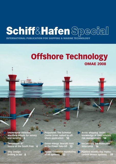
Offshore Technology
Offshore Technology
Offshore Technology

Create successful ePaper yourself
Turn your PDF publications into a flip-book with our unique Google optimized e-Paper software.
�<br />
�<br />
�<br />
Underwater Vehicles:<br />
Maritime robots for survey<br />
and security 3<br />
“Neumayer III”:<br />
Sauna at the South Pole 6<br />
Ship Design:<br />
Drilling in Ice 8<br />
<strong>Offshore</strong> <strong>Technology</strong><br />
�<br />
�<br />
�<br />
Propulsion: The Schottel<br />
Combi Drive: suited to offshore<br />
application 10<br />
Ocean energy: Rexroth rises<br />
to the Power Take-Off 12<br />
Hydac: Condition monitoring<br />
of oil systems 13<br />
�<br />
�<br />
�<br />
OMAE 2008<br />
Arctic shipping: Arctic<br />
knowledge at DNV informs<br />
risk management 14<br />
Ice barriers: Ice Protection<br />
Structures 16<br />
Pipeline monitoring: Hydrocarbon<br />
sensor systems 19
PUBLISHER<br />
DVV Media Group GmbH | Seehafen Verlag<br />
Postbox 10 16 09, D-20038 Hamburg<br />
Nordkanalstraße 36, D-20097 Hamburg<br />
Telefon: +49 (0) 40 2 37 14 - 02<br />
MANAGEMENT<br />
Dr. Dieter Flechsenberger (CEO)<br />
Detlev K. Suchanek<br />
(Publishing Director)<br />
detlev.suchanek@dvvmedia.com<br />
EDITOR<br />
Dr.-Ing. Silke Sadowski (resp.)<br />
Phone: +49 (0) 40 237 14 -143<br />
silke.sadowski@dvvmedia.com<br />
ADVERTISING<br />
Florian Visser (resp.)<br />
Phone: +49 (0) 40 2 37 14 - 117<br />
fl orian.visser@dvvmedia.com<br />
SUBSCRIPTION AND DISTRIBUTION<br />
Riccardo di Stefano<br />
riccardo.distefano@dvvmedia.com<br />
SERVICE<br />
Phone: +49 (0) 40 2 37 14 - 260<br />
Fax: +49 (0) 40 2 37 14 - 243<br />
E-Mail: Service@schiffundhafen.de<br />
������������������<br />
�������������������������<br />
�������������������<br />
�����<br />
��������������������<br />
������������<br />
��������������������������<br />
����������������������<br />
International Publication for Shipping and Marine <strong>Technology</strong><br />
REPRESENTATIVES:<br />
Germany, Austria, Switzerland: Con’Media GmbH<br />
Friedemann Stehr, Bad Hersfeld<br />
Telefon: (0 66 21) 9682930, Fax: (0 66 21) 9682933<br />
fs@friedemann-stehr.de<br />
France AD Presse, E. Costemend, Paris<br />
Telefon: +33 (0) 686646285,<br />
Fax: +33 (0) 1 45 25 14 28<br />
adpi@ad-presse.fr<br />
Great Britain, Ireland: UK Transport Press,<br />
Cuckfi eld<br />
Phone/Fax: +44 (0) 14 44 41 42 93<br />
bernardsteel@uktpl. com<br />
Poland, Russia, Baltic States: Promare Sp.z.o.o.,<br />
Gdynia Phone: +48 (0) 5 86 64 93 92,<br />
Fax: +48 (0) 5 86 64 90 69,<br />
promare@promare.com.pl<br />
Scandinavia, Finland: Örn Marketing AB, Ystad<br />
Phone: +46 (0) 411 1 84 00, Fax: +46 (0) 411 1 05 31<br />
marine.marketing@orn.nu<br />
USA, Canada: Weidner Communications,<br />
Matthew T. Weidner,<br />
Downingtown, PA, USA<br />
Phone: +1 610 486 6565, Fax: +1 610 486 6527<br />
mtw@weidcom.com<br />
SUBSCRIPTION RATES<br />
Germany: EUR 174,00 (incl. postage) plus VAT<br />
Europe: EUR 193,00 (incl. postage)<br />
������������������������������������������<br />
�����������������������������������������<br />
�����������������������������������������<br />
�����������������������������������������<br />
����������������������������<br />
���������������������������������������������<br />
�������������������������������������������<br />
��������������������������������������<br />
��������������������������������������<br />
���������������������������������<br />
�������������������������������������������<br />
��������florian.vi�sser@dvvmedia.com<br />
World: EUR 216,00 (incl. postage)<br />
Single copy: EUR 17,50 (incl. VAT)<br />
SUBSCRIPTION TERMS<br />
The minimum subscription period is one year.<br />
Subscriptions may be terminated at the end of any<br />
subscription period by giving six weeks‘ notice. The<br />
publishers accept no liability if it is impossible to<br />
publish the magazine due to force majeure or any<br />
other cause beyond their control.<br />
COPYRIGHT<br />
The magazine and all the individual articles and<br />
illustrations contained in it are protected by copyright.<br />
It is not permitted to reproduce or distribute<br />
any part of this magazine without the publishers‘<br />
prior written permission. This prohibition extends<br />
in particular to any form or commercial copying,<br />
inclusion in electronic databases or distribution on<br />
CD-ROM or DVD. The publishers are not liable for<br />
unsolicitedly sent manuscripts and images.<br />
PRINT:<br />
Druckerei Knipping, Düsseldorf, Germany<br />
WEB:<br />
ISSN 1436-8498<br />
www.schiffundhafen.de<br />
www.dvvmedia.com
Maritime robots for<br />
survey and security<br />
UNDERWATER VEHICLES Maritime investigations, measurements and inspections with autonomous<br />
underwater vehicles (AUV) are a core element of ATLAS Elektronik to discover the<br />
underwater resources for economic use as well as for the protection of maritime facilities. The<br />
operation under extreme and diffi cult environmental conditions requires the use of robots of<br />
the newest technology with high degree of automation and extreme navigation accuracy.<br />
Willi Hornfeld<br />
Economic use of the seas and<br />
oceans as well as protection of<br />
the ports and their access has a<br />
top-ranking position – the maritime<br />
market has reached world-wide an<br />
enormous order of magnitude. In this<br />
market a German company in general<br />
has not only a strong position, but in<br />
some special maritime engineering<br />
fi elds even a top place. In this environment<br />
the substantial target areas of the<br />
German maritime technologies are:<br />
� The strongly growing and important<br />
market segments such as oil and<br />
gas production from the sea bottom,<br />
underwater mining, exploration and<br />
exploitation of gas hydrates, etc..<br />
� Maritime Homeland Security, one<br />
of the highest priority missions around<br />
the world with the strategic objectives<br />
� Prevent terrorist attacks within and<br />
terrorist exploitation of the national<br />
domain<br />
� Reduce the countries vulnerability<br />
to terrorism within the maritime domain<br />
� Protect the population centres, critical<br />
infrastructure, maritime borders,<br />
ports, coastal approaches, and the<br />
boundaries and seams between them<br />
� Protect the marine transportation<br />
� Minimize the damage and recover<br />
from attacks that may occur in the maritime<br />
domain as either the lead federal<br />
agency or a supporting agency.<br />
One of the core elements for a Maritime<br />
Homeland Security is the protection of<br />
harbours, a razor edge of danger.<br />
Sea Ports and Sea Lanes are the primary<br />
gateways for global trade and<br />
commerce. Ports are the nerve centers<br />
of the international supply chain network.<br />
Operational drop-outs of any of<br />
such critical hubs and bottlenecks will<br />
hence generate consequential damages<br />
on a truly global scale.<br />
The European Sea Ports Organisation<br />
(ESPO) determines that “the Eu- �<br />
Fig. 1: ATLAS’ UUV family<br />
Schiff & Hafen | June 2008 | No. 6 3 Special
SPECIAL | OFFSHORE TECHNOLOGY<br />
Parameter SeaFox<br />
Length [m] 1.3<br />
Width [m] Ø 0.4 (max)<br />
Weight [kg]<br />
Speed [ktd]<br />
40<br />
•max<br />
6<br />
•min<br />
0.5 (backwards)<br />
Diving depth [m] 300/600<br />
Payload [kg] 5<br />
Obstacle avoidance yes<br />
Hover capability yes<br />
Tab.1: SeaFox parameter<br />
Parameter SeaWolf<br />
Length [m] 2.0<br />
Width [m] Ø 0.5 (max)<br />
Weight [kg]<br />
Speed [kts]<br />
110<br />
max<br />
8<br />
min<br />
Minus 0.5<br />
Turn radius < 3 m<br />
Diving depth [m] 3 to 300<br />
Payload [kg] > 30<br />
Obstacle avoidance yes<br />
Hover capability yes<br />
Navigation INS + DVL + (D)GPS +<br />
pressure sensor + compass<br />
Tab. 2: SeaWolf parameter<br />
Parameter SeaOtter Mk2<br />
Length [m] 3.45<br />
Width [m] .90<br />
Height [m] .48<br />
Weight [kg]<br />
Speed [kts]<br />
1000<br />
•max<br />
8<br />
•optimal<br />
4.0<br />
•min<br />
0.5 (backwards) hover<br />
Diving depth [m] 5 to 600<br />
Duration [h] 24 @ 4 kts<br />
Obstacle avoidance Yes<br />
Hoover capability Yes<br />
Navigation MARPOS II<br />
(INS+DVL+DGPS+CTD+ pressure<br />
sensor) & CML<br />
Tab.3 : SeaOtter parameter<br />
� TYPICAL USERS OF UUV´S<br />
�<br />
�<br />
�<br />
�<br />
�<br />
�<br />
�<br />
�<br />
Defence Forces<br />
Coast Guard<br />
Maritime Administration<br />
Customs and<br />
Immigration<br />
Port Authorities<br />
Environmental Agencies<br />
Commercial Operators<br />
Maritime Scientifi c Institutes<br />
Special 4 Schiff & Hafen | June 2008 | No. 6<br />
Fig.2: The SeaFox family<br />
ropean Union without its seas port<br />
cannot act directly. The entire foreign<br />
trade of the community and nearly<br />
half of their domestic trade are almost<br />
conducted via the more than 1,000 sea<br />
ports in the coastal member states of<br />
the European Union.”<br />
Autonomous underwater vehicles<br />
Maritime investigations, measurements<br />
and inspections with autonomous underwater<br />
vehicles (AUV) are a core element<br />
of the above mentioned market<br />
and growth fi elds. The fundamental<br />
pre-condition is however the ability for<br />
precise acting in unknown waters as<br />
well as the technologies for the protection<br />
of maritime facilities (e.g. inspection<br />
of berthing areas, piers and ship<br />
hulls) under extreme and diffi cult environmental<br />
condition. This requires<br />
the use of robots of newest technology<br />
with high degree of automation and<br />
extreme navigation accuracy with high<br />
manoeuvrability.<br />
Such unmanned underwater vehicles are<br />
one of the main product areas of ATLAS<br />
Elektronik. The company has been developing<br />
and delivering such vehicles for<br />
military and commercial applications for<br />
about thirty years. Current products to be<br />
noted are the SeaFox, the SeaWolf and the<br />
SeaOtter Mk II.<br />
The development of these AUVs respectively<br />
HAUVs (Hybrid Autonomous Underwater<br />
Vehicles) happens under consistent<br />
attention of as far as possible synergies<br />
between the individual systems. Beyond<br />
that the underwater vehicles are based substantially<br />
on dual use, i.e. they are designed<br />
for military and commercial missions, with<br />
that due to better serial production fi gures<br />
for the basic systems, a more attractive<br />
price for the customer can be reached. This<br />
philosophy shows Fig.1, the ATLAS UUV<br />
(Unmanned Underwater Vehicles) family<br />
which includes not only the Autonomous<br />
Underwater Vehicles (AUV) but also Remotely<br />
Operated Vehicles (ROV).<br />
A further characteristic of the here<br />
discussed underwater vehicles is their<br />
modularity which, depending on the<br />
specifi c payload capacity, will be realized<br />
by the possibility of plug and<br />
play integration of quasi any payload.<br />
Finally all ATLAS UUVs can be mission-specifi<br />
cally equipped by the user<br />
with a fi ber-optic cable (FOC), so that<br />
a wide-band, real time transmission to<br />
the surface of all sensor and status information<br />
can take place. Such hybrid<br />
AUVs (HAUVs) will open wider and<br />
completely new application areas.<br />
The UUVs SeaFox, SeaWolf and SeaOtter<br />
are characterised by most different<br />
users and several areas of application.<br />
With other the following applications<br />
are standing in the centre:<br />
�<br />
�<br />
�<br />
�<br />
�<br />
�<br />
�<br />
�<br />
�<br />
Mine counter measure<br />
Damage assessment<br />
Intelligence<br />
Rapid environmental assessment<br />
Route survey<br />
Maritime border control<br />
Waterways and port surveillance<br />
Passenger terminal protection<br />
Maritime science.<br />
The following features are, depending<br />
upon payload capacity, realized or will be<br />
realized in the systems:<br />
� Autonomous or operator supported inspection<br />
and classifi cation of all kinds<br />
of underwater areas, structures and objects<br />
� Adaptive autonomy in relation of the<br />
mission<br />
� On line data link via fi bre optic cable<br />
on request (hybrid)<br />
� Operation<br />
areas<br />
in confi ned and tidal<br />
� Inspection sensors of latest techno logies<br />
in underwater vehicles<br />
� Navigation/positioning of highest accuracy
�<br />
�<br />
�<br />
�<br />
�<br />
�<br />
�<br />
�<br />
Standard interfaces for simple integration<br />
of customer specifi ed sensors and<br />
software (plug and play)<br />
High-performance multi sensor image<br />
processing on board or in the surface<br />
console<br />
100% inspection of selected object assured<br />
CAD base inspection on request<br />
CAD object data creation during the inspection<br />
Alarm function in relation to the identifi<br />
ed anomaly<br />
Prepared for team operation<br />
Object oriented mission planning and<br />
control.<br />
The UUV SeaFox is a small and lightweight<br />
(see Tab. 1) vehicle with an endurance<br />
of more than one hour. The<br />
vehicle is available in several confi gurations<br />
from the military systems (SeaFoxC<br />
for mine disposal and SeaFoxI and T<br />
for inspection and training) till the<br />
modular one IQ, predominately used<br />
for commercial survey missions.<br />
Thanks to this modularity, missionadapted<br />
sensor suits with e.g. 360° and<br />
side looking sonar as well as a tiltable TV<br />
system are installable as shown in Fig. 2.<br />
The HAUV SeaWolf is a multirole system<br />
for all kinds of underwater inspection<br />
and anomaly identifi cation.<br />
The propulsion philosophy is comparable<br />
with the Seafox (four main propellers<br />
and one vertical thruster). Due to a<br />
special adjustment of the main motors<br />
a high effi ciency was achieved.<br />
The vehicle is equipped with the latest<br />
sensor and software technologies and<br />
therefore able to inspect autonomously<br />
even very complex 3D objects.<br />
For real time data transfer, the SeaWolf can<br />
be connected with the control console by<br />
a fi bre optic cable. In this case the mission<br />
will be executed autonomously but with a<br />
real time data transfer.<br />
SeaWolf achieves versatility and fl exibility<br />
of mission and payload confi guration<br />
by using plug and play modules<br />
for software, electronic and sensor devices<br />
within a generic architecture.<br />
The vehicle’s basic payload is a side<br />
scan and obstacle detection sonar as<br />
well as a TV camera with LED illumination.<br />
For operation in water with low visibility<br />
a three dimensional high frequency<br />
multibeam sonar and/or a laser projection<br />
unit are additional available. The<br />
navigation is of a very high accuracy and<br />
based on an IMU with DVL and differential<br />
GPS. Therefore the use of an acoustic<br />
positioning system is not necessary.<br />
Due to its relatively low weight, the system<br />
is easy to operate and applicable from all<br />
kind of vessels or from the shore.<br />
Fig.3: SeaWolf confi gurations<br />
Fig.4 : SeaOtter Mk II<br />
The mission planning, control and<br />
evaluation is done from a portable console,<br />
the same as used for the SeaFox.<br />
Tab.2 shows the SeaWolf parameter<br />
and Fig. 3 the system confi guration.<br />
The HAUV SeaOtter Mk II is based on<br />
the proven MARIDAN 600 and the Sea-<br />
Otter Mk I, which have been in operations<br />
throughout the world. Due to the<br />
design and the fl exible payload concept,<br />
the system is easily adaptable to<br />
various military and commercial missions.<br />
The SeaOtter Mk II also offers the benefi t<br />
of a real time data transfer to the operator<br />
consol through the fi bre optic link option.<br />
The standard version of the vehicle<br />
is equipped with side scan sonar, a<br />
multi-beam echo sounder, a sub-bottom<br />
profi ler, obstacle avoidance sonar,<br />
a TV camera and a precise navigation<br />
system.<br />
Due to its serious payload compartment<br />
(approx. 150 kg) the vehicle can<br />
per plug and play be adapted to nearly<br />
all kinds of required missions from<br />
scientifi c till maritime security applications.<br />
Tab. 3 gives the SeaOtter Mk II fi gures<br />
and Fig. 4 an impression of the design.<br />
Willi Hornfeld<br />
ATLAS ELEKTRONIK GmbH, Bremen<br />
Willi.hornfeld@atlas-elektronik.com<br />
www.atlas-elektronik.com<br />
Schiff & Hafen | June 2008 | No. 6 5 Special
SPECIAL | OFFSHORE TECHNOLOGY<br />
Sauna at the South Pole<br />
RESEARCH STATION “NEUMAYER III” Germanischer Lloyd’s Business Segment Oil and Gas<br />
offers its wide range of services all over the world. Just recently the experts also conquered<br />
the ‘sixth continent’: they certify the new research station “Neumayer III”<br />
Not a single ray of sunlight penetrates<br />
the darkness of the polar<br />
winter night. The thermometer<br />
drops below 50°C as storms whip across<br />
the icy landscape. In this environment,<br />
buildings must be designed to withstand<br />
extremely hostile climate conditions.<br />
Materials must be selected carefully and<br />
the functional fi tness of elements must<br />
be tested in realistic simulations.<br />
A house in Antarctica: In December<br />
2006, Germanischer Lloyd received an<br />
order from the Alfred Wegener Polar<br />
and Marine Research Institute (AWI) in<br />
Bremerhaven, Germany, to certify the institute’s<br />
new research station “Neumayer<br />
III” in Antarctica. Even for an experienced<br />
classifi cation society, this project<br />
Assembly of the “Neumayer III“ in<br />
Bremerhaven<br />
Special 6 Schiff & Hafen | June 2008 | No. 6<br />
is rather challenging. The station, named<br />
after the German polar explorer Georg<br />
von Neumayer (1826 to 1909), will consist<br />
of a structure supported by sixteen<br />
hydraulically operated posts. By moving<br />
up and down on these support legs, the<br />
building will adjust continuously to the<br />
changing level of the snow surface. As a<br />
consequence, the research station will<br />
not gradually disappear under masses of<br />
snow, as its predecessor did.<br />
Submerged in ice<br />
After 15 years of operation, the current<br />
Neumayer station has sunk twelve metres<br />
deep into the ice and will have to<br />
be abandoned in the near future. Built<br />
in 1992, the tube-type structure was state<br />
AWI-employees at the underwater<br />
acoustic measuring station “Palaoa“<br />
of the art at the time. But the two steel<br />
tubes that form its outer shell have been<br />
deformed over the years by the movement<br />
of the shelf ice and the constantly<br />
increasing load of snow. Today, the once<br />
elliptical shape of the station is no longer<br />
discernible. Time and again, bolts burst<br />
with a loud bang, unable to withstand<br />
the weight of tons of snow bearing down<br />
on the station. The engineering concept<br />
of the new station consists of a building<br />
to be erected on top of a platform above<br />
the snow surface. The building will accommodate<br />
rooms for research and operations<br />
as well as living quarters.<br />
To construct this unique facility, a pit eight<br />
metres deep will have to be excavated for<br />
the foundations of the hydraulic support<br />
pillars of the station. Later on, the pit will<br />
also be used as a parking area for tracked<br />
vehicles and snowmobiles. A workshop,<br />
the hydraulics centre, exercise rooms and<br />
food stores will be located directly below<br />
the cover of the pit. The station itself will<br />
be positioned on stilts six metres above<br />
snow level so even high winds and dense<br />
snowfall will not cause any major snowdrifts.<br />
The two-story building will be standing<br />
on a platform 68 by 24 metres large<br />
and provide space for common rooms, a<br />
kitchen, an infi rmary and operating theatre,<br />
15 bedrooms with 40 beds, as well as<br />
twelve laboratory and offi ce rooms. Nine<br />
so-called “overwinterers” – scientists, physicians<br />
and technicians – will have nearly<br />
twice as much space for their work as in the<br />
subterranean station “Neumayer II”. For<br />
leisure, there will be a lounge with a bar<br />
and a sauna. Once the basic structure has<br />
been completed, a protective shell 120 mm<br />
thick with a blue, white and red coating<br />
– the colours of the AWI – will be placed<br />
on top of it to reduce wind loading. The<br />
roof offers enough space to accommodate<br />
a chamber for helium sounding balloons,<br />
as well as antennas and other measuring<br />
equipment.<br />
Certified containers<br />
The entire building itself will be assembled<br />
from containers certifi ed by Germanischer<br />
Lloyd. GL has many years of experience<br />
in container certifi cation. Today, the society<br />
certifi es up to 360 000 containers each<br />
year. After the design review, GL subjected<br />
the thermally insulated containers to spe-
The model shows the hydraulic posts of the garage level<br />
cial tests to check their fi tness for transport.<br />
Those tests included stackability, as well as<br />
loading and unloading strength, which ensured<br />
that the containers were taken safely to<br />
Antarctica aboard a Danish freighter. Now,<br />
the GL experts main task is to review the<br />
documentation for safety-relevant equipment<br />
for the entire station – including evacuation<br />
and survival systems, fi re extinguishing<br />
and fi re alarm systems, automation and<br />
alert systems. “Due to the exposed location,<br />
the system as a whole has to meet the most<br />
stringent reliability requirements,” says An-<br />
�BACKGROUND:<br />
ANTARCTICA<br />
The Antarctic Zone comprises the land<br />
and sea areas of the South Pole region.<br />
It covers a surface of approximately 12.5<br />
million square kilometres. 98 percent of<br />
this area is permanently covered by ice.<br />
The continent of Antarctica is located in<br />
the centre of the region. The Antarctic<br />
was explored by various scientists and<br />
seafarers from 1920 onwards.<br />
The continent is characterized by an<br />
extreme climate: It is the coldest, driest<br />
and most wind-ridden part of the earth.<br />
There have been reports of temperature<br />
readings as low as – 89 °C and wind<br />
speeds exceeding 300 km/h. According<br />
to CONMAP (Council of Managers of<br />
National Antarctic Programs), there are<br />
currently more than sixty active research<br />
stations on the continent.<br />
dreas Mäscher, project manager of GL. “In<br />
this respect we can draw on our experience<br />
in offshore installations.”<br />
The AWI order also includes tests of the<br />
energy supply systems as well as the acceptance<br />
inspection of a combustion engine-based<br />
cogeneration plant at the manufacturer<br />
site. “Supplying the station with<br />
heat and energy is a particular challenge,<br />
considering the extreme climate conditions<br />
– low temperatures, large quantities of<br />
snow, high winds,” Andreas Mäscher emphasizes.<br />
Thanks to more effi cient generation<br />
of heat and electricity in the cogeneration<br />
plant, the future station will need only<br />
30 percent more polar diesel (diesel plus<br />
kerosene) than its predecessor although<br />
it is twice as large and will be exposed to<br />
greater wind loading.<br />
GL conducted the component acceptance<br />
tests for both, the diesel-operated<br />
generator and the hydraulically operated<br />
stilts. Last year, the lifting units were tested<br />
under low-temperature conditions to<br />
ensure fl awless operation in the extreme<br />
temperature environment (+4 to -50° C)<br />
of Antarctica.<br />
In November 2007, the components were<br />
loaded onto the Danish freight vessel “Naja<br />
Arctica”, which reached the Antarctic Atka<br />
Bay on schedule in mid-December. However,<br />
a sea ice barrier of several metres<br />
thickness prevented the vessel from moving<br />
ahead. The research icebreaker “Polarstern”<br />
was appointed to free a navigation channel<br />
to the ice edge and helped “Naja Arctica”<br />
to reach her planned unloading position at<br />
the edge of the ice shelf only in mid-January<br />
2008. Despite the one-month delay, the<br />
construction of Neumeyer Station III moved<br />
rapidly ahead in good weather conditions.<br />
In only eight weeks, the entire steelworks of<br />
the underground garage section with 16 hydraulically<br />
operated posts as well as the fi rst<br />
fl oor of the future station were erected. The<br />
unfi nished building is intended to be used<br />
as a store room for construction equipment<br />
and materials until the next Antarctic summer.<br />
The completion of the new station is<br />
scheduled for spring 2009. Then, a GL surveyor<br />
will join the construction site at 70°<br />
40.8‘ south and 8° 16.2‘ west, 6.5 km away<br />
from the old station, to inspect the construction<br />
of the Neumayer III station and<br />
conduct the acceptance tests.<br />
The new research station, which will<br />
cost about 36 million euros, is designed<br />
for a service life of at least 25 years. The<br />
Alfred Wegener Institute, the operator<br />
of “Neumayer III”, will continue its research<br />
activities in Antarctica, recording<br />
important meteorological data and taking<br />
measurements of the earth’s magnetic<br />
fi eld as well as atmospheric readings<br />
of climate-relevant gases. GL will<br />
continue to keep an eye on the station<br />
as well, says Andreas Mäscher: “There<br />
are plans for periodic inspections of the<br />
structure and its equipment.”<br />
Germanischer Lloyd, Hamburg<br />
www.gl-group.com<br />
Schiff & Hafen | June 2008 | No. 6 7 Special
SPECIAL | OFFSHORE TECHNOLOGY<br />
Drilling in ice<br />
SHIP DESIGN The challenge for discovering Arctic oil and gas reserves will be to fi nd solutions to<br />
produce gas and oil with the highest safety and environmental standards. For ice going drill vessels<br />
the Hamburg Ship Model Basin (HSVA) has done various innovative frontier developments.<br />
Karl-Heinz Rupp, Walter L. Kuehnlein<br />
It is estimated that the Arctic<br />
contains more than one third<br />
of the world’s undiscovered<br />
oil and gas reserves. Although<br />
some developments have already<br />
occurred, the region remains<br />
one of the last energy frontiers.<br />
But the region is also one of the<br />
most diffi cult areas in the world<br />
to work at, due to its remoteness,<br />
the extreme cold, dangerous sea<br />
ice and its fragile environment.<br />
Big energy companies are preparing<br />
to go into the Arctic, they<br />
are taking measures in order to<br />
ensure that they will operate<br />
safely and responsibly.<br />
This is not the fi rst run to the<br />
Arctic. Petroleum companies<br />
entered into the Arctic already<br />
half a century ago. Experiences<br />
from past Arctic developments<br />
show the potential hazards of<br />
further exploration. A key challenge<br />
will be developing and<br />
deploying solutions, which are<br />
currently at the cutting edge of<br />
technology. The Arctic Ocean is<br />
the only major sub-basin of the<br />
world’s oceans that has only occasionally<br />
been sampled by deep<br />
sea drilling. Today the properties<br />
of the Arctic Ocean are being<br />
focussed upon by both researchers<br />
and commercial oil and<br />
gas drilling companies. Research<br />
core drilling is of great impor-<br />
tance for the researchers because<br />
it allows them to increase their<br />
knowledge about that large ice<br />
covered area. And of course the<br />
present high prices for energy<br />
make it profi table to explore for<br />
reserves and to produce energy<br />
even in the ice covered waters of<br />
the High North.<br />
Drilling operations in ice have<br />
been already carried out at the<br />
ice border with “open water drill<br />
ships“, mainly with the support<br />
of icebreakers (e.g. “Joides Resolution”<br />
with “Maersk Master”).<br />
Some drill ships are reinforced<br />
for operation in ice, but this reinforcement<br />
is limited to the<br />
strengthening of the ship structure<br />
and does not include the propulsion<br />
and operational outfi tting.<br />
An ice-breaking drill ship should<br />
be capable of keeping its position<br />
so that the drilling operation can<br />
be continued, also when it is surrounded<br />
by drifting ice.<br />
Existing concepts and<br />
d esigns<br />
Some of the challenges which<br />
a drill ship in ice will experience,<br />
have been already described<br />
in 1983 (Dynamic<br />
Response of a Moored Drill<br />
ship to an Advancing Ice<br />
Cover, T. Kotras, A. Baird, E.<br />
Corona, Poac 83, Volume 3,<br />
Fig.1.: The cross section shows the sloped side of<br />
the HSVA drill ship design with ice accumulated<br />
Special 8 Schiff & Hafen | June 2008 | No. 6<br />
page 433, Helsinki, Finland,<br />
1983):<br />
� “The ability of a vessel to stay<br />
within a prescribed operational<br />
radius is greatly enhanced when<br />
impacting ice in a head-on condition.<br />
Beam-on collisions cause<br />
excursions from two to fi ve times<br />
larger as those occurring head-on.<br />
� The ability of a drill ship to<br />
quickly yaw into a heading inline<br />
with the advancing ice is<br />
directly related to the maximum<br />
excursion seen.<br />
� In the Bering Sea, an unassisted<br />
drill ship may not be capable<br />
of year round operation during<br />
the heavy ice periods, ...“.<br />
Almost 30 years ago, in 1980, a<br />
drill-platform from Gulf Canada<br />
(Conical Drilling Unit) was tested<br />
in ice by HSVA. It was found<br />
that the rig could operate in an<br />
environment up to about one<br />
meter level ice thickness. This<br />
platform, the “Kulluk“, was kept<br />
in position with a mooring system.<br />
The shape of the platform<br />
was circular in the plan view<br />
and the section was similar to<br />
an asymmetrical sandglass. The<br />
turret was placed in the centre of<br />
this fl oating island. This platform<br />
was not suitable for being moved<br />
over a long distance at sea.<br />
In the last decade improvements<br />
in manoeuvrability and<br />
Fig.2: Side view of “Aurora Borealis“ with two moonpools<br />
(as designed by HSVA)<br />
ice breaking performance have<br />
been achieved by applying<br />
azimuth propulsors. Nowadays<br />
several ice going and ice<br />
breaking vessels, e.g. icebreakers,<br />
supply vessels, tankers and<br />
multi-purpose container vessels<br />
are equipped with this type<br />
of propulsion system.<br />
New technical developments<br />
In 2000 contracted the Alfred-<br />
Wegener-Institut (AWI) in<br />
Bremerhaven Germany (www.<br />
awi-bremerhaven.de) the Hamburgische-SchiffbauVersuchsanstalt<br />
(HSVA) to carry out a<br />
draft design study for an Arctic<br />
Drilling Research Vessel with<br />
dynamic positioning capabilities<br />
in ice. The project was entitled<br />
“Aurora Borealis”.<br />
Drifting ice may change in both<br />
in speed and direction. Furthermore<br />
the ice conditions vary<br />
from easy to heavy (e.g. ice<br />
ridges), therefore the drill ship<br />
must be able to keep position<br />
within a very narrow margin. All<br />
of these requirements, as well as<br />
the technological developments<br />
described above have been taken<br />
into consideration for HSVA’s<br />
conceptual design for the “Aurora<br />
Borealis”.<br />
The technical features of the<br />
HSVA design are:
� Low ice resistance of the drill<br />
ship at both bow and stern. This<br />
was achieved with an optimized<br />
icebreaking hull shape, similar<br />
to that of an icebreaker.<br />
� High ability to turn the vessel<br />
in ice in order to follow changes<br />
in ice drift. This was achieved by<br />
implementing a strong slope at<br />
the side of the vessel (see cross<br />
sections). This hull shape allows<br />
the vessel to break ice over<br />
the entire ship length. In order<br />
to break the ice the azimuth<br />
propulsors deliver the required<br />
thrust for turning the drill ship.<br />
� The vessel is able to operate in<br />
ice without icebreaker assistance<br />
up to very severe ice conditions,<br />
far above of the capabilities of<br />
all existing ice going drill vessels.<br />
With icebreaker assistance the<br />
operational limits of the drilling<br />
vessel can be further extended.<br />
� Consequently, the HSVA<br />
design is the fi rst design world<br />
wide, which will allow drilling<br />
in ice with a dynamic positioning,<br />
i.e. no fi xed mooring system<br />
will be required.<br />
The HSVA design study for “Aurora<br />
Borealis” has been presented<br />
in several publications and presentations<br />
since 2001. The fi gures<br />
1 and 2 are from: European Polar<br />
Board (EPB), Aurora Borealis “A<br />
long term European Science Perspective<br />
for Deep Arctic Ocean<br />
Research 2006-2016”, June 2004.<br />
Logistics in ice management<br />
In addition to the technological<br />
improvements, the logistics in<br />
ice management are also of great<br />
importance.<br />
The use of modern satellite ice<br />
and weather data are a fi rst step<br />
for obtaining information about<br />
the ice conditions ,ice drift speed<br />
and drifting direction over a large<br />
area. Closer to the drill ship, ice<br />
drift speed and direction can<br />
be detected by sensors installed<br />
on board of the drill vessel. The<br />
ice thickness can be measured<br />
with electro magnetic ice thickness<br />
measurement devices and<br />
together with visual ice observations,<br />
severe ice conditions can<br />
be detected and traced, and the<br />
potential danger to the drill ship<br />
can be calculated and predicted.<br />
An example for excellent ice<br />
management was the core drilling<br />
research work of “Vidar Viking”<br />
in 2004 close to the North<br />
Pole. “Vidar Viking” was built<br />
as an ice breaking supply vessel<br />
and was equipped with a drilling<br />
rig. The vessel alone was not able<br />
to keep position during drilling<br />
in the Arctic ice, although<br />
it is equipped with a dynamic<br />
positioning system (DP) for ice<br />
free waters. Manual DP in ice<br />
was only possible in well managed<br />
ice. The Russian nuclear<br />
icebreaker “Sowjetski Sojus“ and<br />
the Swedish Icebreaker “Oden“<br />
broke the drifting ice into small<br />
pieces (well managed ice).<br />
Tests with a moored drilling<br />
vessel in drifting ice<br />
HSVA has tested several drilling,<br />
production and storage vessels in<br />
managed and in well managed<br />
ice. In these tests the ice drift is<br />
supposed to hit the vessel under<br />
different angles. Such “oblique<br />
towing tests” generate large deviations<br />
to the vessel’s position<br />
and the corresponding loads in<br />
the mooring systems. During<br />
the last few years HSVA has designed<br />
and/or optimized several<br />
of these vessels and consequently<br />
HSVA has gained a tremendous<br />
amount of expertise for such<br />
highly complex systems in ice.<br />
As an example: From 2006 until<br />
2008, HSVA carried out several<br />
ice model testing campaigns for<br />
a moored drilling vessel for the<br />
Norwegian engineering company<br />
LMG Marin in Bergen and<br />
Statoil (now StatoilHydro). The<br />
tests demonstrated the excellent<br />
ice breaking capabilities of the<br />
unit in level ice of up to 1.60m<br />
thickness, in ice ridges and in ice<br />
rubble fi elds. The main target of<br />
the investigations was to develop<br />
a concept for enabling the vessel<br />
to follow the ice drift change in<br />
order to keep the vessel within<br />
the range of the lowest ice resistance<br />
and therefore within the<br />
defi ned operational working<br />
area. The pictures 3–6 give an<br />
overview of several ice scenarios<br />
which have been tested.<br />
Dr. Karl-Heinz Rupp,<br />
Dr. Walter L. Kuehnlein<br />
Hamburg Ship Model Basin<br />
(HSVA), Hamburg<br />
Rupp@hsva.de<br />
Kuehnlein@hsva.de<br />
www.HSVA.de<br />
Fig. 3: The vessel is rotated around the centre of the turret<br />
using the thrust of the azimuth propulsors<br />
Fig. 4: The propeller wash is a useful tool for breaking ice or to<br />
wash ice away from the vessel<br />
Fig. 5: Track behind the drill ship after an ice drift course<br />
change of 20°<br />
Fig. 6: Tests in broken irregular thick ice<br />
Schiff & Hafen | June 2008 | No. 6 9 Special
SPECIAL | OFFSHORE TECHNOLOGY<br />
The Schottel Combi Drive:<br />
suited to offshore application<br />
PROPULSION Schottel which develops, designs, manufactures and sells propulsion and<br />
manoeuvring systems with power ratings of up to 30 MW for vessels of all<br />
types and sizes set new standards for the manoeuvrability in the<br />
early 1950s with their Schottel Rudderpropeller (SRP).<br />
The SCHOTTEL Combi Drive (SCD) combines the main technical<br />
and economic criteria of both mechanical Rudderpropellers<br />
and pod drives.<br />
Schottel builds combi drives both in<br />
a twin-propeller version and as a<br />
ducted single-propeller system, at<br />
present covering a power range from 2,100<br />
to 3,300 kW. In contrast to pod drives with<br />
an electric motor inside the underwater<br />
pod, the motor in the Combi Drive is integrated<br />
vertically into the support tube of<br />
the Rudderpropeller. Neither an above-water<br />
gearbox nor a cardan shaft is required,<br />
making the system extremely compact and<br />
easy for the shipyard to install in the vessel<br />
with very low space requirements.<br />
Since the market launch, 16 of these innovative<br />
propulsion systems have already<br />
successfully entered everyday service. Three<br />
double-ended ferries built for Fjord1<br />
Fylkesbaatane in Norway by the shipyard<br />
Aker Brattvaag AS are each equipped with<br />
four gas-electric powered Schottel Combi<br />
Drives of type SCD 2020 in twin-propeller<br />
confi guration (4 x 2,750 kW). The ferries<br />
operate between Bergen and Stavanger.<br />
An ecological and safety-oriented concept<br />
The SCD has a promising future in the offshore<br />
sector. The Norwegian Ulstein Verft,<br />
for example, has chosen it as the propulsion<br />
system for two platform supply vessels<br />
of type PX105. These 4700 dwt ships<br />
with the distinctive Ulstein X-Bow were<br />
built for the shipping company Bourbon<br />
<strong>Offshore</strong> Norway IS KS, a subsidiary of the<br />
French Group Bourbon, based in Marseille.<br />
With their new bow, they are “highly-developed,<br />
large and reliable multifunctional<br />
platform supply vessels, which distinguish<br />
themselves particularly in terms of fuel<br />
consumption, good sea-going characteristics,<br />
positioning, speed, stability and loading<br />
capacity”, as the shipyard emphasizes.<br />
Both vessels are equipped with two<br />
SCD 2020 twin-propeller systems (max.<br />
2,700 kW). The decision to combine a<br />
diesel-electric propulsion concept with<br />
an azimuth drive system means a signifi -<br />
cant improvement to the performance of<br />
Special 10 Schiff & Hafen | June 2008 | No. 6<br />
the vessels. The concept allows fl exible<br />
power distribution and offers a higher<br />
degree of redundant safety. The lower fuel<br />
consumption also makes the PSVs more<br />
environmentally friendly.<br />
The shipping company had stipulated that<br />
the vessels were to be equipped in accordance<br />
with the requirements of the DNV<br />
Clean Design Class. This means that<br />
the equipment had to meet strict<br />
criteria with regard to its environmental<br />
impact. BP Norway, the<br />
operator, also stressed that the<br />
ecological and safety-related<br />
concept of the new vessels had<br />
played a decisive role in the<br />
awarding of the contract.<br />
The economic expectations<br />
of Bourbon <strong>Offshore</strong> Norway<br />
with regard to these two innovative<br />
vessels were quickly confi rmed<br />
with the result that the company has<br />
mean while placed a further order with<br />
Ulstein Design for the design and technical<br />
equipment of four more vessels of the<br />
same type, also with Schottel SCD 2020<br />
Combi Drives. The construction contract<br />
was awarded to Zhejiang Shipbuilding Co.<br />
Ltd. in Zhejiang, China. The shipyard will<br />
be delivering the vessels in late 2009 or<br />
early 2010.<br />
Both Neptune <strong>Offshore</strong> in Norway and EDT<br />
on Cyprus have ordered two further vessels<br />
of the same design in the mean time.<br />
US owners such as Otto Candies LLC in<br />
New Orleans, a major offshore shipping<br />
company in the Gulf of Mexico, are also<br />
focussing on this innovative propulsion<br />
concept. For two of its new offshore supply<br />
vessels, built by Dakota Creek Industries<br />
(DCI), the company has chosen the Combi<br />
Drive. The ships are each to be equipped<br />
with two SCD 2020 systems (2 x 2,250 kW<br />
and 2 x 2,500 kW).<br />
Following the successful market launch of<br />
the twin-propeller version, intensive market<br />
research culminated in the decision to<br />
introduce a ducted variant of the SCD.<br />
Ducted variant of the SCD<br />
While the twin-propeller SCD is mostly<br />
used in vessels with an operating profi le<br />
in the transit range at medium to high<br />
speeds, the ducted propeller operates at<br />
its best in the lower speed range and at<br />
static thrust. Especially for vessels with<br />
an operating profi le characterized by dynamic<br />
positioning (DP) and partial-load<br />
operation, the ducted variant represents<br />
a particularly effi cient solution.<br />
Anchor Handling Tug Supply vessels<br />
(AHTS), seismic research vessels, cable<br />
ships and other work vessels are ideally<br />
suited to this propulsion solution. This<br />
presupposes, of course, that the vessels<br />
are equipped with a diesel-electric propulsion<br />
system. This is usually the case<br />
with cable ships or seismic research vessels;<br />
AHTS vessels, however, are still an<br />
exception – and not always with good<br />
reason, as investigations have shown.
Side view of a new <strong>Offshore</strong> Supply Vessel for Otto Candies LLC in New Orleans Design: MMC Ship Design & Marine Consulting, Ltd, Poland<br />
A diesel-electric propulsion system is<br />
endowed with a power management system<br />
that ensures that only the currently<br />
required power is generated and distributed<br />
to the various units in the vessel.<br />
The connected generators always run at<br />
the optimum operating point. In combination<br />
with a ducted fi xed-pitch propeller,<br />
as in the Schottel Combi Drive,<br />
such a system offers very high effi ciency,<br />
especially in the low-load range.<br />
In a diesel-electric fi xed-pitch system, the<br />
required thrust is regulated via the electric<br />
motor speed (frequency control).<br />
The connected generators run at the optimized<br />
operating point – as does the<br />
fi xed-pitch propeller if designed accordingly.<br />
Furthermore, for low to medium<br />
vessel speeds, a well-designed fi xed-pitch<br />
propeller with frequency control is more<br />
effi cient at the rated speed than a controllable-pitch<br />
propeller.<br />
Increased economic efficiency<br />
The space saved by the diesel-electric concept,<br />
together with the fl exible design of<br />
the vessel’s interior (the SCD requires no<br />
space-intensive shaft lines), result in a substantial<br />
increase in the usable volume. This<br />
is of particular importance with such complex<br />
vessels as AHTS, and increases their<br />
economic effi ciency.<br />
These arguments convinced the shipowner<br />
Great <strong>Offshore</strong> Ltd., based in Mumbai, India,<br />
so that it ordered for the fi rst time a<br />
150 t anchor handling tug with diesel-electric<br />
propulsion and two ducted SCD 3030s<br />
(2 x 3,300 kW) from Bharati Shipyard Ltd.<br />
in Mumbai. The newbuilding is scheduled<br />
to go into service at Great <strong>Offshore</strong> at the<br />
end of 2008.<br />
The trend towards diesel-electric powered<br />
vessels has sharply increased over the last<br />
few years. This is due to the fact that particularly<br />
work vessels in offshore operations<br />
are becoming ever more complex. Moreover,<br />
the leading seafaring nations in this<br />
segment, such as Norway or the USA, are<br />
enforcing more restrictive environmental<br />
and climate protection measures.<br />
Above all in harbours, the amount of pollutants<br />
emitted by conventional diesel engines<br />
is considerable, due to operation in<br />
the unfavourable partial-load range. Under<br />
the working title of “Green Tug”, dieselelectric<br />
concepts for harbour tugs have for<br />
the fi rst time now been developed in the<br />
USA for the harbours in Los Angeles and<br />
Houston. For example, in Los Angeles it<br />
is planned to allow tugs to operate only<br />
under battery power in the city area of the<br />
harbour. In the outer area of the harbour,<br />
the batteries can then be recharged via the<br />
generators. If such plans are implemented<br />
– and there are many arguments in their<br />
favour – the Schottel Combi Drive undoubtedly<br />
represents the optimal propulsion<br />
solution for harbour tugs meeting these<br />
requirements.<br />
Schottel GmbH<br />
Spay/Rhein<br />
www.schottel.de<br />
The platform supply vessel “Bourbon Mistral“ has already fulfi lled the shipping<br />
company´s economic expectation in just a short space of time. Photo: Tony Hall<br />
Schiff & Hafen | June 2008 | No. 6 11 Special
SPECIAL | OMAE 2008<br />
Wave ernergy utilisation<br />
Rexroth rises to the Power Take-Off<br />
UTILIZING OCEAN ENERGY One of the main challenges at the concept of ocean power stations<br />
which extract power from ocean energy lies in devising a suitable “power-take off“ system for<br />
converting the kinetic energy of the water into electrical power<br />
Nik Scharmann<br />
Experts tell us that within a few decades,<br />
innovative systems for the<br />
sustainable use of ocean energy may<br />
generate as much electricity as 150–200<br />
nuclear power stations.<br />
On the one hand the important advantages<br />
of utilizing ocean energy here is that around<br />
two third of the world‘s inhabitants live in<br />
coastal regions. The close proximity of ocean<br />
power stations to consumers simplifi es the<br />
infrastructure and minimizes power losses.<br />
On the other hand ocean energy is always<br />
available: tides, currents, and – to a certain<br />
extent – sea swells are ever present, thus enabling<br />
more long-term planning. As a result,<br />
ocean power stations are a much better option<br />
for providing the base load of the electricity<br />
networks.<br />
A number of companies are currently working<br />
on different concepts for large-scale facilities<br />
that will extract power from this renewable<br />
energy source. The main challenge lies<br />
in devising a suitable “power-take off“ system<br />
for converting the kinetic energy of the<br />
water to electrical power while ensuring that<br />
generation costs remain competitive. The<br />
development of the plants and the necessary<br />
PTOs is only in its infancy, but Rexroth is<br />
already supporting numerous projects with<br />
tailored solutions, just as it did for wind<br />
energy a few decades ago. These solutions<br />
Special 12 Schiff & Hafen | June 2008 | No. 6<br />
are based on Rexroth hydraulic components<br />
and cross-technology systems, which have<br />
already proven extremely robust and reliable<br />
in a range of maritime applications.<br />
The ocean energy industry currently consists<br />
of two main sectors: tidal energy and<br />
wave energy.<br />
Tidal energy<br />
Tidal power stations use the energy of currents<br />
to power rotors – be they tidal or natural<br />
sea currents. Water has a density one<br />
thousand times greater than air and can thus<br />
generate signifi cant power even from low<br />
fl ow velocities. This requires specifi cally tailored<br />
solutions.<br />
The diameter of underwater rotors does not<br />
have to be large for them to be able to con-<br />
Mechanic Power-Take-Off<br />
duct energy effectively. Even at low speeds,<br />
the forces acting on the entire system are<br />
signifi cant. Rexroth is currently pursuing a<br />
development concept that adopts the generator<br />
gearbox technology employed in the<br />
wind energy sector, an area in which the<br />
company has established itself as a worldleading<br />
supplier for renewable energies.<br />
Research is also being conducted into the<br />
use of hydraulic converters. This simple yet<br />
highly robust concept transforms rotary<br />
motion into hydraulic fl ow, which powers<br />
an adjustable hydraulic motor for the generator<br />
with great effi ciency. A slow-running<br />
radial piston motor with constant displacement<br />
is employed on the pump side. It<br />
generates a volumetric current based on the<br />
rotor speed. A fast-running axial piston dis-
placement motor is connected on the motor<br />
side, which can be fi tted directly to the<br />
generator shaft. The motor-generating set is<br />
then operated directly at mains frequency.<br />
There is no need for elaborate control electronics<br />
or frequency converters. It is also<br />
possible to implement a continuous transmission<br />
ratio. The system can thus be used<br />
to quench short-term peak demand while<br />
also enabling long-term adaptation to the<br />
changing current fl ow rates throughout the<br />
tide cycle. A pitch system is not required.<br />
Since the displacement motors employed<br />
can be operated in dual-quadrant mode, it<br />
is even possible to reverse the direction of<br />
the rotor when the tide changes. It is not<br />
necessary to rotate the system. Another advantage<br />
of this system is the positioning of<br />
the gearbox components: while the highly<br />
robust radial piston pump is installed under<br />
water, the motor-generating set remains<br />
above water.<br />
However, the high level of fl exibility of a<br />
hydrostatic power train over a mechanical<br />
gearbox results in lower effi ciency overall. It<br />
is not yet clear which power train technology<br />
will eventually prevail, but it will certainly<br />
depend on the activities of the plant suppliers.<br />
Increased effi ciency, particularly in the<br />
case of the fast-running displacement motors,<br />
could result in the hydraulic concept<br />
gaining the upper hand.<br />
Wave energy<br />
Fluid technology is particularly well suited<br />
to meeting the requirements of wave energy<br />
utilization. In a system with a nominal<br />
power of 150 kW, travel speeds will gener-<br />
ally range between 1 and 2 m/s at forces of<br />
500 kN to 1 MN. It should be noted that<br />
the maximum forces and speeds do not<br />
correlate: high travel speeds are usually the<br />
result of small waves over short periods,<br />
while high forces are produced by high<br />
waves over longer periods.<br />
The challenge for the PTO is posed by the<br />
specifi c attribute of waves: within a wave period,<br />
the input power of the machine fl uctuates<br />
twice between zero and the maximum<br />
value. A typical wave period lasts 10 s, i.e.<br />
0.1 Hz; the main frequency is between 50<br />
and 60 Hz. This effectively requires a transmission<br />
ratio of i = 500-600. Furthermore,<br />
the power of a wave increases approximately<br />
with the square of the signifi cant wave<br />
height. As a result, a power ratio of 1/100 can<br />
soon develop between the lower and upper<br />
operating window of the WEC (wave energy<br />
converter).<br />
Efficiency is not everything<br />
From a technical point of view, the effi -<br />
ciency of the PTO is the fi rst target variable<br />
Condition monitoring of oil systems<br />
HYDAC | One customer of Hydac AS competent<br />
clientele is Maskindynamikk AS in<br />
Spjelkavik, which develops complete solutions<br />
for periodic and continuous monitoring<br />
of rotating machinery with varying<br />
loads. Maskindynamikk has extensive experience<br />
with vibration analysis and have now<br />
implemented Hydac’s particle counter if oil<br />
cleanliness should be monitored as well.<br />
The hydraulic market shows great interest<br />
in monitoring oil cleanliness through online<br />
particle counting, relative humidity<br />
and pressure measurements. This makes<br />
it possible to use condition based maintenance<br />
instead of periodic solutions. The<br />
advantages are many, but of course to have<br />
maximum up-time on the machinery to a<br />
minimized price is the most important one.<br />
The fear of choosing an alarm point which<br />
could be wrong has been one of the most<br />
diffi cult obstacles in the way of condition<br />
based maintenance. If it is able to defi ne<br />
what is „normal“ it is also possible to defi ne<br />
Hydrostatic Power-Take-Off<br />
what is irregular. With continuous signals<br />
Maskindynamikk’s system is able to „learn“<br />
and defi ne what is normal and one is able<br />
to use all logic ( „OR“, „AND“, „THEN“ etc.)<br />
commands to interconnect different signals<br />
which give the basis for the alarm. This<br />
to catch the eye: the more effi ciently a PTO<br />
converts the energy, the more electricity<br />
is produced. However, the target variable<br />
that will ultimately overshadow all activities<br />
is the cost of electricity generation in<br />
c/kWh. As well as the afore mentioned<br />
system effi ciencies, this index also incorporates<br />
the facility costs, including operating<br />
and maintenance costs, as well as the<br />
service life of the installed systems. Only<br />
a comprehensive optimization of all variables<br />
will lead to the minimization of electricity<br />
production costs.<br />
The development of a WEC and PTO that<br />
generates competitively priced electricity<br />
under the described conditions is a challenge<br />
which the entire industry is currently<br />
tackling with great vigor.<br />
Nik Scharmann<br />
Bosch Rexroth AG, Lohr a. Main<br />
nik.scharmann@boschrexroth.de<br />
www.boschrexroth.com<br />
Example: Thruster systems for ships are a very good example of a system which is<br />
interesting to monitor. Both the manufacturers and the ship owners are very interested<br />
in online monitoring of the condition of the thruster system. If the monitoring<br />
system is approved by a classifi cation society, it is possible to reduce the amount of<br />
visual inspections of these systems.<br />
means an alarm triggers only if it’s real and<br />
important to act upon.<br />
HYDAC International GmbH,<br />
Sulzbach/Saar<br />
offshore@hydac.com<br />
www.hydac.com<br />
Schiff & Hafen | June 2008 | No. 6 13 Special
SPECIAL | OFFSHORE TECHNOLOGY<br />
Arctic knowledge at DNV<br />
informs risk management<br />
ARCTIC SHIPPING DNV has class notations covering the entire spectrum of cold climate operations<br />
ranging from control of icing in open waters to ice-breaking abilities in temperatures<br />
as low as -55˚C and in recognition of the rapidly changing physical and business environment in<br />
the Arctic. This offers now greater fl exibility in winterisation notations.<br />
Wendy Laursen<br />
As recently as two years ago, it was estimated<br />
that the north-eastern Arctic<br />
shipping route would be open for<br />
most of the year in ten to 15 years time, but<br />
the latest Norwegian research predicts that<br />
this may happen earlier than that. Icebergs<br />
forming in the region, some weighing over<br />
six million tonnes, are the largest moving<br />
objects on earth.<br />
Johan Tutturen, DNV business director for<br />
tankers, presented research results at the<br />
Mare Forum, Athens, in March 2008 that<br />
quantifi ed the value of the most important<br />
risk control options for Arctic shipping.<br />
Based on a shuttle tanker project intended<br />
for operation in Arctic waters, the research<br />
used known risk elements from worldwide<br />
operation but added additional risk elements<br />
for both cold climate and ice.<br />
The project revealed that redundant propulsion<br />
offers a 6 % reduction in the likelihood<br />
of accidents involving collision,<br />
grounding, fi re and explosion. Use of an<br />
automatic identifi cation system and electronic<br />
chart display as well as information<br />
systems offer a further 6 % reduction. Setting<br />
high standards in bridge resource management<br />
and the selection and trai ning of<br />
crew can reduce risk by 44 % and minimising<br />
noise and vibration levels when travelling<br />
through ice can reduce risk by a further<br />
12 %.<br />
Previous studies have shown that ships<br />
built with additional DNV class notations<br />
for nautical and bridge safety experience<br />
risk reductions of nearly 50 %. Most accidents<br />
at sea are caused by human error<br />
and harsh climatic conditions can result<br />
in poor quality rest, reduced alertness and<br />
concentration and poor speech intelligibility.<br />
The main objective of DNV’s NAUT notation<br />
is to reduce the risk of human failure<br />
in bridge operations by specifying requirements<br />
for workplace design, equipment<br />
standards and operational procedures.<br />
“There are many types of mitigating measures<br />
that can be introduced to reduce cold<br />
stress and they should be considered as<br />
safety investments,” says Tutturen. “It all<br />
boils down to risk management: identify-<br />
ing the hazards, measuring specifi c risk elements<br />
and the way they interact and then<br />
evaluating and implementing control options.”<br />
Oil and gas recovery in the Arctic is increasing<br />
and DNV undertakes feasibility studies<br />
and concept evaluations for these cold<br />
climate activities. They use integrated risk<br />
management tools that assess the total investment<br />
risk over the full project life cycle.<br />
Factors such as component reliability and<br />
production profi les are used to develop<br />
forecasting models and the use of probability<br />
distributions in simulation model<br />
input parameters allows uncertainty and<br />
variation to be used in the development<br />
of a quantifi ed risk picture for any revenue<br />
stream.<br />
“It is vitally important that ship owners<br />
contemplating Arctic operations are<br />
aware of the possible challenges connected<br />
with their intended trading patterns.<br />
Our research capability, extensive<br />
experience and state-of-the-art simulation<br />
techniques bring value to these of-<br />
“Arctic Discoverer“ will be trading out of Hammerfest close to the Barents Sea. The vessel is managed by K Line and classed to DNV. Photo: DNV<br />
Special 14 Schiff & Hafen | Juni 2008 | Nr. 6
ten multi-billion dollar decision making<br />
processes,” said Tutturen.<br />
Once a project is live, DNV can assist with<br />
quality control, maintenance and repair<br />
evaluations. Vessel category and availability<br />
can be an important consideration and<br />
limited accessibility for remedial action if<br />
incidents occur means extra planning effort<br />
is essential for safe Arctic operations.<br />
The protection of Arctic and sub-Arctic environments<br />
has been of increasing importance<br />
in recent years. Petroleum and shipping<br />
companies are facing rising demand<br />
for environmental safety. DNV participates<br />
in baseline studies and environmental<br />
monitoring. Their environmental risk<br />
analysis approach gives decision makers a<br />
transparent and effi cient tool for identifying<br />
and quantifying risk due to accidental<br />
oil spills. It includes probabilistic oil drift<br />
modelling and toxicity and impact assessments<br />
on sensitive environmental resources.<br />
Their contingency planning toolkit<br />
includes an electronic map interface for oil<br />
spill response operations that is distributed<br />
in real time to all involved parties.<br />
More tanker operators are looking to venture<br />
into the Arctic as a means of shortening voyage<br />
times from Europe to Japan and the US.<br />
“Allowing for changing climatic conditions<br />
is an important consideration on a day-today<br />
basis for ship operators but I believe that<br />
operating fl exibility will grow in importance<br />
in the future,” said Tutturen. “This is already<br />
the case with the newbuildings we are involved<br />
in. Hull fatigue damage accumulation<br />
is about twice as rapid in North Atlantic<br />
conditions compared to the comparatively<br />
more benign environment of traditional<br />
LNG routes, for example, and there is an increasing<br />
trend amongst owners to specify 40<br />
years of fatigue life in the North Atlantic to<br />
ensure trouble free operation in these more<br />
demanding cold climates.”<br />
Traditional open water accidents such as<br />
groundings and collisions are more likely<br />
to occur in cold climates. Fires are responsible<br />
for 10 % of all fatalities at sea and fi re<br />
fi ghting in severe weather is more complicated<br />
and therefore more likely to cause<br />
critical damage. In addition to this, new<br />
sources of accident are introduced in cold<br />
climates. Ice may damage a vessel or force<br />
it aground. Icebergs and ice fl oes can cause<br />
serious damage to a vessel in the zone between<br />
open sea and solid ice and sea spray<br />
can lead to severe icing and damage from<br />
the clogging of vents and the freezing of<br />
pipes.<br />
Extra notations<br />
DNV has been delivering standards for<br />
ice class shipping since 1881. Currently,<br />
over 1900 vessels carry DNV ice class<br />
notations, including the four highest<br />
specifi cation LNG carriers in operation.<br />
They incorporate Finnish and Swedish<br />
Maritime Authorities’ rules in their Baltic<br />
specifi cations and although unifi ed International<br />
Association of Classifi cation<br />
Society rules are under development,<br />
DNV’s extra notations offer a greater<br />
depth of operational security based on<br />
extensive experience and intimate local<br />
knowledge. Safe ship operations require<br />
more than just ice strengthening of the<br />
ship’s structure and propeller, says Tutturen,<br />
and DNV has developed technical<br />
standards for all ship’s equipment and<br />
structures where reliability is important.<br />
DNV’s latest Winterised notations have<br />
been expanded effective 1 January 2008.<br />
The notations recognise that some vessels<br />
spend shorter times in cold climates<br />
than others and the expanded rules defi ne<br />
three different levels of cold climate safety<br />
design. Each has separate designations for<br />
temperature in material selection and extreme<br />
temperature performance. Nevertheless,<br />
emergency features relating to escape<br />
exits, lifeboats, towing and evacuation play<br />
an important part in all notations.<br />
The highest level, Winterised Arctic, is<br />
for ships such as ice breakers that are<br />
operating in the harshest cold climate<br />
conditions and the notation calls for redundant<br />
propulsion. “A loss of power in<br />
extremely low temperatures can quickly<br />
lead to a critical situation and freezing of<br />
water and vital parts in the engine room<br />
may reduce the possibility of a re-start.<br />
Ideally, a blackout period longer than<br />
ten minutes should be avoided,” says<br />
Johan Tutturen. “Emergency generators<br />
should be located in a tempered location<br />
to avoid starting problems at low<br />
temperatures and additional heating arrangements<br />
ensure that temperatures in<br />
the engine room are maintained above<br />
freezing point during a blackout.”<br />
Winterised Basic and Winterised Cold cater<br />
for vessels operating in cold climates on a<br />
seasonal basis. Winterised Basic includes<br />
anti-icing precautions for communication<br />
and navigation equipment, sea chests,<br />
fi re fi ghting capacity and some vents and<br />
valves. Winterised Cold specifi es additional<br />
requirements including temperature<br />
protection for equipment and spaces, stability<br />
under ice loads and the use of low<br />
temperature steel for some of the structures<br />
above the waterline.<br />
Vessels travelling in the Arctic tend to try<br />
and follow the same ice channel as each<br />
other to navigate a path of least resistance<br />
and often the most favourable ice conditions<br />
will be close to shore. In practice,<br />
though, ships may sometimes operate under<br />
heavier ice conditions that those stipulated<br />
for their ice class. As well the safety<br />
risks associated, this can bring vessels into<br />
contact with the Russian authorities.<br />
“Arctic Discoverer“ will be crossing the<br />
Northern Atlantic where the weather<br />
condition will create challenges Photo: DNV<br />
DNV’s established relations with Russian<br />
institutions, means that they can offer valuable<br />
assistance in meeting local regulations.<br />
In Russian waters, it may be necessary for a<br />
vessel to have an ice passport. This is not<br />
a building standard but a description of<br />
safe operating modes for a particular vessel<br />
based on how the ship is actually built. It<br />
is based on the ship’s structure, hull lines,<br />
dimensions, displacement, propulsion<br />
power, propeller thrust, age and the state<br />
of the shell plating.<br />
DNV contributes actively to the development<br />
of technical and operational codes<br />
and directives for offshore petroleum activity<br />
in the Arctic and they proactively maintain<br />
their position at the forefront of research<br />
and risk management solutions for<br />
cold climate business. Over the next three<br />
to six years their strategic research initiatives<br />
are focusing on extreme ice shipping<br />
and human responses to the associated<br />
cold, noise and isolation. They will also research<br />
best practice emergency evacuation<br />
from ships and platforms in the Arctic and<br />
work on achieving a greater understanding<br />
of the ever-changing Arctic environment<br />
from a risk acceptance perspective.<br />
Wendy Laursen<br />
Det Norske Veritas<br />
wlaursen@bigpond.com<br />
www.dnv.com<br />
Schiff & Hafen | June 2008 | No. 6 15 Special
SPECIAL | OFFSHORE TECHNOLOGY<br />
Ice protection structures<br />
ICE BARRIERS For over 25 years IMPaC <strong>Offshore</strong> Engineering has gained substantial<br />
knowledge and experience in numerous ice engineering projects. One area of special expertise<br />
is the design of ice protection structures.<br />
Joachim Berger<br />
The increasing demand for<br />
hydrocarbons requires<br />
offshore exploration and<br />
production drilling activities<br />
in ice infested areas. In shallow<br />
water areas like the North Caspian<br />
Sea, purpose-designed ice<br />
protection structures also called<br />
ice barriers can lead to solutions<br />
that provide technical and economical<br />
advantages compared<br />
to fi eld developments without<br />
ice protection measures.<br />
For the protection of offshore<br />
production facilities in shallow<br />
water areas permanent ice<br />
barriers made from rock or<br />
concrete structures are often<br />
the appropriate solution. For<br />
drilling exploration facilities,<br />
which usually have to change<br />
their location after they have<br />
sunk the well, ice barriers made<br />
from steel are mostly the better<br />
solution as they are easier to install<br />
and de-install.<br />
Ice barriers can also be used to<br />
protect offshore wind parks or<br />
harbour installations.<br />
Advantages<br />
Ice barriers allow designing<br />
of an exploration platform or<br />
other offshore facility for re-<br />
duced ice loads. The ice load reduction<br />
is a function of the type<br />
and number of ice barriers.<br />
Less expenditure for the protected<br />
platform requires additional<br />
costs for the design<br />
construction, installation and<br />
operation of the ice barriers.<br />
However ice barrier structures<br />
also considerably improve the<br />
conditions under which supply<br />
of the offshore unit is possible.<br />
In some cases platforms<br />
can only be operated during<br />
the winter season with ice barriers<br />
in place. Also during the<br />
non-ice season ice barriers can<br />
improve the platform supply<br />
conditions by reducing wave<br />
heights in the vicinity of the<br />
offshore installation. Thus, ice<br />
barriers can considerably extend<br />
the availability of the platform<br />
with large positive effect<br />
on the overall economics of the<br />
offshore fi eld operation.<br />
Ice barriers can also be required<br />
to facilitate evacuation of the<br />
crew from the platform under<br />
ice conditions. Production on<br />
offshore platforms has to be<br />
stopped under extreme environmental<br />
conditions where rubble<br />
ice piles prevent the emergency<br />
evacuation of personnel. Therefore,<br />
ice barriers whilst protecting<br />
the integrity of the offshore<br />
platform structure also increase<br />
the availability of the platform’s<br />
production, thus improving the<br />
economics of the project.<br />
Requirements<br />
An ice protection structure has<br />
to be a simple, yet robust structure<br />
as it is exposed to harsh environmental<br />
conditions and has<br />
to withstand large ice loads. The<br />
main requirement on ice barriers<br />
is a high technical reliability at a<br />
minimum material expenditure.<br />
For the protection of mobile<br />
units like offshore exploration<br />
drilling rigs the de-installation<br />
and re-use of an ice barrier are<br />
also of importance.<br />
Full compliance with environmental<br />
protection requirements<br />
is mandatory for all ice barriers.<br />
Determination of design<br />
loads<br />
The technical reliability of<br />
an ice protection structure is<br />
strongly dependent on the correct<br />
ice load. In some cases especially<br />
in dee per water areas<br />
the hydrodynamic forces due to<br />
waves and current can become<br />
the dominating load situation.<br />
Deterministic methods are<br />
mostly applied to predict the<br />
ice loads as the data basis for a<br />
probabilistic approach is often<br />
insuffi cient.<br />
When the ice protection structure<br />
is of simple geometry analytical<br />
methods can be applied<br />
to establish the ice loads. When<br />
the shape of the ice barrier is<br />
too complicated for analytical<br />
methods ice model tests have<br />
to be carried out.<br />
In practice, the prediction of<br />
ice loads is not the major challenge<br />
but the determination<br />
of realistic full-scale ice conditions<br />
from which the ice loads<br />
will be derived. The uncertainty<br />
in the ice load conditions and<br />
the lack of full-scale data often<br />
require a conservative design<br />
approach and do not allow full<br />
design optimisation of the ice<br />
barrier structure.<br />
Due to the lack of ice data<br />
satellite imaging has been utilised<br />
to determine ice conditions.<br />
The satellite images allow<br />
a fairly good estimate of<br />
the ice coverage and the thickness<br />
of sheet ice. But in many<br />
Fig. 1: Drilling unit with driven piles as ice protection structure Fig. 2: Ice protection piles, view from drilling unit<br />
Special 16 Schiff & Hafen | June 2008 | No. 6
Fig. 3: Drilling unit with barge type ice barriers to protect against excessive ice loads<br />
cases the dominating ice loads<br />
for an ice protection structure<br />
result from the interaction<br />
with pressure ridges, which<br />
cannot be identifi ed from the<br />
satellite pictures. In such cases<br />
fi eld observations and surveys<br />
are of particular importance.<br />
Driven piles as ice protection<br />
structure<br />
Driven piles have been used as<br />
ice protection means at the fi rst<br />
two exploration sites of a mobile<br />
drilling barge, which has<br />
been operating since 1998 in<br />
the shallow water areas of the<br />
North Caspian Sea. The piles<br />
also serve as berthing and mooring<br />
piles for the supply vessels.<br />
The optimum pile arrangement<br />
has been determined in<br />
ice model tests. The main parameters<br />
infl uencing the ice<br />
load reduction for a given ice<br />
thickness are pile diameter<br />
and pile spacing. With the optimised<br />
pile arrangement the<br />
ice loads could be reduced by<br />
60 percent compared to the solution<br />
without any piles.<br />
Simple pontoons as ice protection<br />
structures<br />
As a larger number of wells<br />
had to be drilled as originally<br />
Fig. 4: Design options for optimised barge type ice barriers<br />
structures<br />
anticipated the piles have been<br />
replaced at later sites by pontoons,<br />
which have the advantage<br />
of easy re-usage.<br />
After de-ballasting and refl<br />
oating the ice barrier barge<br />
can be towed to the next exploration<br />
site of the drilling<br />
unit. At the drilling site the<br />
ice barrier barge needs to be<br />
ballasted with sea water in<br />
order to create suffi cient sliding<br />
resistance. In some cases<br />
concrete can be used as fi xed<br />
ballast. However, due to draft<br />
limitations fi xed ballast cannot<br />
always be used. Due to<br />
the simple geometrical form<br />
of the barge type ice barriers<br />
the ice loads could be established<br />
by analytical methods.<br />
How ever, for establishing the<br />
minimum number of ice barrier<br />
barges and their optimal<br />
arrangement relative to the<br />
drilling unit ice model tests<br />
have been carried out.<br />
In future, ice model tests may<br />
only be required for verifi cations<br />
purposes as latest developments<br />
of computer models<br />
allow a relatively good analytical<br />
simulation of the interaction<br />
of drifting ice with ice<br />
barriers of different arrangement.<br />
�<br />
Fig. 5: Ice barrier structure providing shelter for a supply<br />
vessel<br />
Schiff & Hafen | June 2008 | No. 6 17 Special
SPECIAL | OFFSHORE TECHNOLOGY<br />
Fig. 6: Sketch of a light-weight ice barrier © IMPaC<br />
Purpose-designed ice protection<br />
barges<br />
Various types of barges have<br />
been developed by IMPaC<br />
aimed to optimise performance<br />
as an ice barrier.<br />
The vertical wall design has<br />
been compared to sloped<br />
walls with different slope angles.<br />
For sheet ice the sloped<br />
surface has advantages but often<br />
the interaction with pressure<br />
ridges is the dominating<br />
load scenario for which the<br />
slope angle of the wall is of<br />
lesser importance.<br />
Ice protection barges with<br />
one vertical long wall have<br />
advantages during site installation<br />
and de-installation or<br />
when the barge needs to be<br />
moored in a harbour or yard<br />
for inspection purposes. During<br />
operation the vertical wall<br />
normally facing towards to the<br />
drilling unit has the advantage<br />
of providing a berthing and<br />
mooring place for marine<br />
boats and barges.<br />
Sloped walls also have the advantage<br />
of smaller local ice<br />
loads compared to vertical<br />
walls. The weight of the steel<br />
shell of a barge type ice barrier<br />
strongly depends on the size<br />
and distribution of the local<br />
ice loads. The smaller the ice<br />
load exposed area considered<br />
in the stress analysis the lar ger<br />
the local design ice load to be<br />
applied. The distribution of<br />
the local ice loads including<br />
so-called “ice background pressures”<br />
acting on the sloped or<br />
vertical shell usually leads to a<br />
vertical stiffening of the shell.<br />
For economical reasons plastic<br />
deformations of the outer<br />
steel plate and the stiffening<br />
bulb profi les are normally accepted<br />
while stresses in frames<br />
and bulkheads have to remain<br />
within the elastic range.<br />
In Figure 5, a barge type ice<br />
barrier with one sloped and<br />
one vertical wall is shown,<br />
providing shelter for an ice<br />
breaking supply vessel.<br />
While the local ice loads have a<br />
large impact on the design of the<br />
steel shell the global ice loads<br />
usually dictate the overall height<br />
and bottom width of barge type<br />
ice protection structure.<br />
Fig. 7: Light-weight ice barrier with accumulated rubble ice and<br />
indicated ice drift direction<br />
Special 18 Schiff & Hafen | June 2008 | No. 6<br />
The ice barrier has to provide<br />
suffi cient sliding and overturning<br />
resistance. In very<br />
shallow water areas sliding<br />
failure is more of a risk than<br />
overturning.<br />
When the seabed is of the<br />
non-cohesive type (sand)<br />
the overall design of the ice<br />
barrier is weight driven. The<br />
larger the contact pressure<br />
from the bottom plate to the<br />
top layer of the seabed, the<br />
larger the sliding resistance of<br />
the ice protection barge. The<br />
sliding resistance can be further<br />
improved by using skirts.<br />
Spray ice could also be used<br />
to increase the weight of the<br />
barrier. The larger weight of<br />
the barrier structure leads to<br />
larger sliding resistance.<br />
When the seabed is of the cohesive<br />
type (clay) the footprint<br />
of the ice barrier becomes important<br />
while the weight has<br />
less impact on the sliding resistance.<br />
At sites with cohesive<br />
seabed material, underwater<br />
berms or backberms can lead<br />
to an improvement of the sliding<br />
resistance.<br />
Light-weight ice protection<br />
structure<br />
IMPaC has developed a light<br />
weight ice barrier structure,<br />
which is based on the idea<br />
that the broken ice pieces will<br />
be collected and the mass of<br />
the accumulated rubble ice<br />
contributes to the overall resistance<br />
of the barrier.<br />
The principle of the lightweight<br />
ice barrier can be seen<br />
in Figure 6. It shows the fi rst<br />
stage of the interaction with<br />
drifting ice in early winter<br />
when relative thin ice has<br />
failed at the sloped wall and<br />
the broken ice piece start to<br />
accumulate.<br />
Various ice model tests have<br />
been carried out to verify the<br />
function of the light-weight<br />
ice barrier. The ice model<br />
tests were also performed to<br />
measure the ice forces acting<br />
on the structure during<br />
the different phases of the<br />
interaction with drifting ice<br />
features. Also the mass of the<br />
accumulated ice was determined<br />
which allowed checking<br />
the sliding stability of the<br />
light-weight barrier structure.<br />
Figure 7 shows the situation<br />
after the light-weight ice barrier<br />
has been fi lled-up with<br />
rubble ice.<br />
The research project was supported<br />
by the German Federal<br />
Ministry of Education and Research.<br />
Outlook<br />
Future exploration and production<br />
activities in the North<br />
Caspian Sea and other ice infested<br />
shallow water areas will<br />
require a considerable amount<br />
of ice protection structures,<br />
which need to be designed,<br />
built and operated.<br />
IMPaC <strong>Offshore</strong> Engineering<br />
will continue to play a leading<br />
role in the realisation of these<br />
projects and also in the future<br />
development of new ice protection<br />
technologies.<br />
Joachim Berger<br />
IMPaC <strong>Offshore</strong> Engineering<br />
Hamburg<br />
berger@impac.de<br />
www.impac.de
Hydrocarbon sensor systems<br />
PIPELINE MONITORING To improve detection effi ciency and to eliminate the need to introduce<br />
additional potential pollutants to underwater pipeline systems CONTROS has developed a new leak<br />
detection method, a “Hydrocarbon Sniffer System”, called HydroC.<br />
Daniel Esser<br />
The global demand for energy<br />
challenges the offshore<br />
oil & gas industry to go for<br />
deeper regions and the arctic<br />
areas. However, environmental<br />
awareness and concern puts the<br />
focus on effective and reliable<br />
monitoring systems to avoid leaks<br />
and spills of harmful fl uids.<br />
Subsea production systems are<br />
getting more and more common<br />
for these applications. Globally<br />
subsea pipelines and production<br />
systems are becoming a major<br />
concern as authorities are less tolerant<br />
to leaks of polluting material<br />
into the marine environment.<br />
In this respect, the ability to detect<br />
and also to locate any leakage of<br />
oil or gas to the surrounding water<br />
and environment is of utmost<br />
importance to safeguard a green<br />
and healthy planet.<br />
At a depth of 3,000 meters operation<br />
of a subsea production<br />
installation is a great challenge<br />
and a high risk. Not only are the<br />
costs for deep sea installation<br />
high, but the risk for the environment<br />
is evident – is it possible to<br />
detect or repair a leak?<br />
Subsea fi eld development and<br />
long pipeline transport may be<br />
the only alternative to develop a<br />
deep sea installation; if suffi cient<br />
water depths, infrastructure on<br />
the seafl oor can be advantageous.<br />
However, in Arctic areas where<br />
the surface ice and iceberg conditions<br />
can be problematic. Subsea<br />
processing is regarded as an effi -<br />
cient way to safe energy; reduce<br />
the use of chemicals and to reduce<br />
discharge of produced water.<br />
In the past three main methods<br />
of subsea leak detection have<br />
been used for leaks where obvious<br />
visual signs of large leaks<br />
such as bubbles, large clouds,<br />
etc. are either not present or have<br />
failed to locate these problems.<br />
These three main methods used<br />
are fl uorometric measurement,<br />
pig-systems (not useable for all<br />
types of pipelines of today) and<br />
passive acoustics, which listen<br />
for ultrasound created by fl uid<br />
leaking under pressure.<br />
The systems mostly used these<br />
days for permanent monitoring<br />
or pipeline inspection by ROV<br />
(Remotely Operated Vehicle) or<br />
AUV (Autonomous Underwater<br />
Vehicle) seem all to have disadvantages<br />
in detecting very small<br />
and non visible oil or gas leaks.<br />
In an effort to fi nd new leak detection<br />
methods that improve<br />
detection effi ciency and also<br />
eliminate the need to introduce<br />
additional potential pollutants to<br />
pipeline systems, CONTROS has<br />
been working on a “Hydrocarbon<br />
Sniffer System” called HydroC<br />
for the last fi ve years. This unique<br />
system which is now available<br />
has a worldwide patented optical<br />
analysing system. Hydrocarbon<br />
molecules diffuse through a special<br />
membrane (which keeps the<br />
water out) and enters into the detector<br />
chamber. The adsorption<br />
of light in gas leads to change<br />
of intensity which is measured<br />
electronically. The HydroC can<br />
detect the higher order chain<br />
of hydrocarbons or just CH 4 if<br />
Methane is of primary interest;<br />
which is a huge advantage as CH 4<br />
is the smallest molecule in nearly<br />
every crude oil and natural gas.<br />
A system can consist of one HydroC<br />
or an array of sniffers, current<br />
meters and other instrumentation<br />
required covering a large<br />
subsea installation or an area of<br />
manifolds. This HydroC system<br />
is unaffected by turbidity or<br />
other interferences such as H 2 S<br />
or any other gaseous substances<br />
in the environment. This system<br />
was developed specifi cally to allow<br />
fast, real-time and in-situ detection<br />
of dissolved and gaseous<br />
hydrocarbons/methane in water,<br />
whatever the source. It has been<br />
successful used in hydrocarbon<br />
surveys and pipeline inspections<br />
to water depth up to 3,000 metres<br />
worldwide.<br />
The very high sensitivity (down<br />
to 30 nmol/l) of the HydroC<br />
Monitoring of critical paths and pipelines<br />
system also makes it ideal for<br />
the detection of methane seepage<br />
from the seabed. Here it is<br />
also widely used for the exploration<br />
and the production process<br />
of methane hydrates in different<br />
projects around the world.<br />
CONTROS is also partner of the<br />
German Gashydrate Organisation<br />
(www.german-gashydrate.<br />
org) where another CONTROS<br />
HydroC instrument for CO2<br />
detection is used for the CO2<br />
sequestration process, which<br />
has become an important topic<br />
for the international oil companies.<br />
The calibrated HydroC<br />
(Hydrocarbon or CO 2 ) plug &<br />
play system records data ei ther<br />
internally or externally in units<br />
of hydrocarbon or methane concentration.<br />
By careful logging<br />
around an area of leakage from<br />
a pipeline, the seabed or a manifold,<br />
an estimate of the amount<br />
of leaking gas or oil can be made<br />
directly. HydroC is in use by<br />
several pipeline inspection companies<br />
and CONTROS has close<br />
cooperation with the leading<br />
ROV manufacturers to equip<br />
their inspection ROV’s with the<br />
latest leak detection technology.<br />
In summary CONTROS provides<br />
offshore pipeline inspection<br />
and long term monitoring solutions.<br />
HydroC leak detection<br />
product line, fi eld experience<br />
and advanced data management<br />
systems meet demanding regulatory<br />
requirements and enhancing<br />
safety during production from<br />
subsea production systems.<br />
Daniel Esser<br />
CONTROS Systems &<br />
Solutions GmbH, Kiel<br />
d.esser@contros.eu<br />
www.contros.eu<br />
Schiff & Hafen | June 2008 | No. 6 19 Special
Oil and Gas: a new perspective<br />
Your business is oil and gas – and our business is your safety. From industrial plant to pipelines, from planning to maintenance,<br />
whether its advice, testing or certification you require: Germanischer Lloyd Oil and Gas (GLO) is your reliable serviceprovider<br />
when it comes to verification, certification and quality assurance for your systems – anywhere in the world. Our range of services<br />
revolves around the safety and health of people, the protection of the environment, and the securing of investments.<br />
Welcome to GLO, your partner for the utmost safety, on- and offshore.<br />
Germanischer Lloyd Industrial Services GmbH<br />
Oil and Gas<br />
Steinhöft 9 · 20459 Hamburg, Germany<br />
Phone +49 40 36149-750 · Fax +49 40 36149-1707<br />
glo@gl-group.com · www.gl-group.com/glo