Offshore Technology
Offshore Technology
Offshore Technology

You also want an ePaper? Increase the reach of your titles
YUMPU automatically turns print PDFs into web optimized ePapers that Google loves.
SPECIAL | OFFSHORE TECHNOLOGY<br />
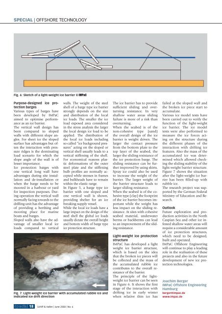
Fig. 6: Sketch of a light-weight ice barrier © IMPaC<br />
Purpose-designed ice protection<br />
barges<br />
Various types of barges have<br />
been developed by IMPaC<br />
aimed to optimise performance<br />
as an ice barrier.<br />
The vertical wall design has<br />
been compared to sloped<br />
walls with different slope angles.<br />
For sheet ice the sloped<br />
surface has advantages but often<br />
the interaction with pressure<br />
ridges is the dominating<br />
load scenario for which the<br />
slope angle of the wall is of<br />
lesser importance.<br />
Ice protection barges with<br />
one vertical long wall have<br />
advantages during site installation<br />
and de-installation or<br />
when the barge needs to be<br />
moored in a harbour or yard<br />
for inspection purposes. During<br />
operation the vertical wall<br />
normally facing towards to the<br />
drilling unit has the advantage<br />
of providing a berthing and<br />
mooring place for marine<br />
boats and barges.<br />
Sloped walls also have the advantage<br />
of smaller local ice<br />
loads compared to vertical<br />
walls. The weight of the steel<br />
shell of a barge type ice barrier<br />
strongly depends on the size<br />
and distribution of the local<br />
ice loads. The smaller the ice<br />
load exposed area considered<br />
in the stress analysis the lar ger<br />
the local design ice load to be<br />
applied. The distribution of<br />
the local ice loads including<br />
so-called “ice background pressures”<br />
acting on the sloped or<br />
vertical shell usually leads to a<br />
vertical stiffening of the shell.<br />
For economical reasons plastic<br />
deformations of the outer<br />
steel plate and the stiffening<br />
bulb profi les are normally accepted<br />
while stresses in frames<br />
and bulkheads have to remain<br />
within the elastic range.<br />
In Figure 5, a barge type ice<br />
barrier with one sloped and<br />
one vertical wall is shown,<br />
providing shelter for an ice<br />
breaking supply vessel.<br />
While the local ice loads have a<br />
large impact on the design of the<br />
steel shell the global ice loads<br />
usually dictate the overall height<br />
and bottom width of barge type<br />
ice protection structure.<br />
Fig. 7: Light-weight ice barrier with accumulated rubble ice and<br />
indicated ice drift direction<br />
Special 18 Schiff & Hafen | June 2008 | No. 6<br />
The ice barrier has to provide<br />
suffi cient sliding and overturning<br />
resistance. In very<br />
shallow water areas sliding<br />
failure is more of a risk than<br />
overturning.<br />
When the seabed is of the<br />
non-cohesive type (sand)<br />
the overall design of the ice<br />
barrier is weight driven. The<br />
larger the contact pressure<br />
from the bottom plate to the<br />
top layer of the seabed, the<br />
larger the sliding resistance of<br />
the ice protection barge. The<br />
sliding resistance can be further<br />
improved by using skirts.<br />
Spray ice could also be used<br />
to increase the weight of the<br />
barrier. The larger weight of<br />
the barrier structure leads to<br />
larger sliding resistance.<br />
When the seabed is of the cohesive<br />
type (clay) the footprint<br />
of the ice barrier becomes important<br />
while the weight has<br />
less impact on the sliding resistance.<br />
At sites with cohesive<br />
seabed material, underwater<br />
berms or backberms can lead<br />
to an improvement of the sliding<br />
resistance.<br />
Light-weight ice protection<br />
structure<br />
IMPaC has developed a light<br />
weight ice barrier structure,<br />
which is based on the idea<br />
that the broken ice pieces will<br />
be collected and the mass of<br />
the accumulated rubble ice<br />
contributes to the overall resistance<br />
of the barrier.<br />
The principle of the lightweight<br />
ice barrier can be seen<br />
in Figure 6. It shows the fi rst<br />
stage of the interaction with<br />
drifting ice in early winter<br />
when relative thin ice has<br />
failed at the sloped wall and<br />
the broken ice piece start to<br />
accumulate.<br />
Various ice model tests have<br />
been carried out to verify the<br />
function of the light-weight<br />
ice barrier. The ice model<br />
tests were also performed to<br />
measure the ice forces acting<br />
on the structure during<br />
the different phases of the<br />
interaction with drifting ice<br />
features. Also the mass of the<br />
accumulated ice was determined<br />
which allowed checking<br />
the sliding stability of the<br />
light-weight barrier structure.<br />
Figure 7 shows the situation<br />
after the light-weight ice barrier<br />
has been fi lled-up with<br />
rubble ice.<br />
The research project was supported<br />
by the German Federal<br />
Ministry of Education and Research.<br />
Outlook<br />
Future exploration and production<br />
activities in the North<br />
Caspian Sea and other ice infested<br />
shallow water areas will<br />
require a considerable amount<br />
of ice protection structures,<br />
which need to be designed,<br />
built and operated.<br />
IMPaC <strong>Offshore</strong> Engineering<br />
will continue to play a leading<br />
role in the realisation of these<br />
projects and also in the future<br />
development of new ice protection<br />
technologies.<br />
Joachim Berger<br />
IMPaC <strong>Offshore</strong> Engineering<br />
Hamburg<br />
berger@impac.de<br />
www.impac.de