Chapter 5 Part A: Ignition system - carburettor models
Chapter 5 Part A: Ignition system - carburettor models
Chapter 5 Part A: Ignition system - carburettor models

You also want an ePaper? Increase the reach of your titles
YUMPU automatically turns print PDFs into web optimized ePapers that Google loves.
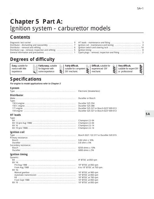
5A•1<br />
<strong>Chapter</strong> 5 <strong>Part</strong> A:<br />
<strong>Ignition</strong> <strong>system</strong> - <strong>carburettor</strong> <strong>models</strong><br />
Contents<br />
Diagnostic test socket . . . . . . . . . . . . . . . . . . . . . . . . . . . . . . . . . . . . 9<br />
Distributor - dismantling and reassembly . . . . . . . . . . . . . . . . . . . . . 7<br />
Distributor - removal and refitting . . . . . . . . . . . . . . . . . . . . . . . . . . . 6<br />
Distributor cap - removal, inspection and refitting . . . . . . . . . . . . . . 5<br />
General information and precautions . . . . . . . . . . . . . . . . . . . . . . . . 1<br />
HT leads - maintenance and fitting . . . . . . . . . . . . . . . . . . . . . . . . . . 3<br />
<strong>Ignition</strong> coil - maintenance and testing . . . . . . . . . . . . . . . . . . . . . . . 4<br />
<strong>Ignition</strong> switch and steering lock . . . . . . . . . . . . . . . . . . . . . . . . . . . . 10<br />
<strong>Ignition</strong> timing . . . . . . . . . . . . . . . . . . . . . . . . . . . . . . . . . . . . . . . . . . 8<br />
Spark plugs - removal, inspection and fitting . . . . . . . . . . . . . . . . . . 2<br />
Degrees of difficulty<br />
Easy, suitable for<br />
novice with little<br />
experience<br />
1<br />
Specifications<br />
Fairly easy, suitable<br />
for beginner with<br />
some experience<br />
For engine to model applications refer to <strong>Chapter</strong> 2<br />
System<br />
Type . . . . . . . . . . . . . . . . . . . . . . . . . . . . . . . . . . . . . . . . . . . . . . . . . . . .<br />
2<br />
Fairly difficult,<br />
suitable for competent<br />
DIY mechanic<br />
Electronic (breakerless)<br />
Difficult, suitable for<br />
experienced DIY<br />
mechanic<br />
Distributor<br />
Make . . . . . . . . . . . . . . . . . . . . . . . . . . . . . . . . . . . . . . . . . . . . . . . . . . . . Ducellier or Bosch<br />
Type:<br />
150 A engine . . . . . . . . . . . . . . . . . . . . . . . . . . . . . . . . . . . . . . . . . . . . Ducellier 525 354<br />
150 C engine . . . . . . . . . . . . . . . . . . . . . . . . . . . . . . . . . . . . . . . . . . . . Ducellier 525 388<br />
171 engine . . . . . . . . . . . . . . . . . . . . . . . . . . . . . . . . . . . . . . . . . . . . . Ducellier 525 327 or Bosch 0237 009 013<br />
159 engine . . . . . . . . . . . . . . . . . . . . . . . . . . . . . . . . . . . . . . . . . . . . . Ducellier 525 327 or Bosch 0237 009 013<br />
HT leads<br />
Type:<br />
BX . . . . . . . . . . . . . . . . . . . . . . . . . . . . . . . . . . . . . . . . . . . . . . . . . . . . Champion LS-04<br />
BX 14 (pre Aug 1988) . . . . . . . . . . . . . . . . . . . . . . . . . . . . . . . . . . . . . Champion LS-04<br />
BX 16 . . . . . . . . . . . . . . . . . . . . . . . . . . . . . . . . . . . . . . . . . . . . . . . . . Champion LS-14<br />
BX 19 (pre 1988) . . . . . . . . . . . . . . . . . . . . . . . . . . . . . . . . . . . . . . . . . Champion LS-14<br />
<strong>Ignition</strong> coil<br />
Type . . . . . . . . . . . . . . . . . . . . . . . . . . . . . . . . . . . . . . . . . . . . . . . . . . . . Bosch 0221 122 317 or Ducellier 520 015<br />
Primary resistance:<br />
Bosch . . . . . . . . . . . . . . . . . . . . . . . . . . . . . . . . . . . . . . . . . . . . . . . . . 0.82 ohm ± 10%<br />
Ducellier . . . . . . . . . . . . . . . . . . . . . . . . . . . . . . . . . . . . . . . . . . . . . . . 0.8 ohm ± 5%<br />
Secondary resistance:<br />
Bosch . . . . . . . . . . . . . . . . . . . . . . . . . . . . . . . . . . . . . . . . . . . . . . . . . 8250 ohms ± 10%<br />
Ducellier . . . . . . . . . . . . . . . . . . . . . . . . . . . . . . . . . . . . . . . . . . . . . . . 6000 ohms ± 5%<br />
<strong>Ignition</strong> timing<br />
Dynamic:<br />
BX . . . . . . . . . . . . . . . . . . . . . . . . . . . . . . . . . . . . . . . . . . . . . . . . . . . . 8º BTDC at 850 rpm<br />
BX 14:<br />
Pre Aug 1988 . . . . . . . . . . . . . . . . . . . . . . . . . . . . . . . . . . . . . . . . . 10º BTDC at 850 rpm<br />
From Aug 1988 . . . . . . . . . . . . . . . . . . . . . . . . . . . . . . . . . . . . . . . . 6 to 10º BTDC at 750 rpm<br />
BX 16:<br />
Manual gearbox . . . . . . . . . . . . . . . . . . . . . . . . . . . . . . . . . . . . . . . 10º BTDC at 900 rpm<br />
Automatic transmission . . . . . . . . . . . . . . . . . . . . . . . . . . . . . . . . . 10º BTDC at 850 rpm<br />
RE . . . . . . . . . . . . . . . . . . . . . . . . . . . . . . . . . . . . . . . . . . . . . . . . . . 10º BTDC at 700 rpm<br />
From Sept 1988 . . . . . . . . . . . . . . . . . . . . . . . . . . . . . . . . . . . . . . . 10º BTDC at 850 rpm<br />
BX 19 . . . . . . . . . . . . . . . . . . . . . . . . . . . . . . . . . . . . . . . . . . . . . . . . . 10º BTDC at 850 rpm<br />
3<br />
4<br />
Very difficult,<br />
suitable for expert DIY<br />
or professional<br />
5<br />
5A
5A•2 <strong>Ignition</strong> <strong>system</strong> - <strong>carburettor</strong> <strong>models</strong><br />
Spark plugs Type Electrode gap<br />
BX . . . . . . . . . . . . . . . . . . . . . . . . . . . . . . . . . . . . . . . . . . . . . . . . . . . . Champion S9YCC / S281YC 0.8 mm / 0.6 mm<br />
BX 14:<br />
Pre Aug 1988 . . . . . . . . . . . . . . . . . . . . . . . . . . . . . . . . . . . . . . . . . Champion S9YCC / S281YC 0.8 mm / 0.6 mm<br />
From Aug 1988 . . . . . . . . . . . . . . . . . . . . . . . . . . . . . . . . . . . . . . . . Champion RC9YCC / C9YCX 0.8 mm / 0.8 mm<br />
BX16:<br />
Pre Sept 1988 . . . . . . . . . . . . . . . . . . . . . . . . . . . . . . . . . . . . . . . . . Champion S7YCC / S279YC 0.8 mm / 0.6 mm<br />
From Sept 1988 . . . . . . . . . . . . . . . . . . . . . . . . . . . . . . . . . . . . . . . Champion RC7YCC / C7YCX 0.8 mm / 0.8 mm<br />
BX 19:<br />
Pre July 1987 . . . . . . . . . . . . . . . . . . . . . . . . . . . . . . . . . . . . . . . . . Champion S7YCC / S279YC 0.8 mm / 0.6 mm<br />
From July 1987 . . . . . . . . . . . . . . . . . . . . . . . . . . . . . . . . . . . . . . . . Champion RC7YCC / C7YCX 0.8 mm / 0.8 mm<br />
Torque wrench settings Nm lbf ft<br />
Spark plugs:<br />
Taper seat type . . . . . . . . . . . . . . . . . . . . . . . . . . . . . . . . . . . . . . . . . . 12 9<br />
Flat seat type (with washer) . . . . . . . . . . . . . . . . . . . . . . . . . . . . . . . . 25 18<br />
1 General information and<br />
precautions<br />
General information<br />
The ignition <strong>system</strong> fitted to all <strong>carburettor</strong><br />
equipped <strong>models</strong> is of the electronic type and<br />
comprises a 12 volt battery, a high output coil,<br />
a transistorised module, a distributor with a<br />
magnetic impulser generator and spark plugs<br />
(see illustration).<br />
The <strong>system</strong> relies on the distributor to<br />
produce an electrical pulse at each firing<br />
point. This pulse is produced by magnetic<br />
induction and is amplified by the ignition<br />
module which supplies LT current to the coil.<br />
HT voltage is generated and distributed in the<br />
traditional fashion.<br />
Electronic ignition <strong>system</strong>s are normally<br />
very reliable. Because the effects of contact<br />
breaker wear have been eliminated, the<br />
<strong>system</strong> will not go ‘off tune’.<br />
Precautions<br />
It is necessary to take extra care when<br />
working on the electrical <strong>system</strong> to avoid<br />
damage to semi-conductor devices (diodes<br />
and transistors), and to avoid the risk of<br />
personal injury. Take note of the following<br />
points:<br />
a) Before disconnecting any wiring, or<br />
1.1 <strong>Ignition</strong> <strong>system</strong> circuit diagram<br />
1 <strong>Ignition</strong> switch<br />
2 Earth/condenser (radio)<br />
3 Coil<br />
4 Distributor<br />
5 Module<br />
6 Tachometer<br />
7 Diagnostic socket<br />
If the code is preceded by the letter F, it denotes the wire colour. Otherwise it denotes the sleeve colour
<strong>Ignition</strong> <strong>system</strong> - <strong>carburettor</strong> <strong>models</strong> 5A•3<br />
removing components, always ensure that<br />
the ignition is switched off.<br />
b) Always remove rings, watches, etc.<br />
before working on the ignition <strong>system</strong>.<br />
Even with the battery disconnected,<br />
capacitive discharge could occur if a<br />
component live terminal is earthed<br />
through a metal object. This could cause<br />
a shock or nasty burn.<br />
c) Do not reverse the battery connections.<br />
Components such as the alternator or any<br />
other having semi-conductor circuitry<br />
could be irreparably damaged.<br />
d) If the engine is being started using jump<br />
leads and a slave battery, connect the<br />
batteries positive to positive and negative<br />
to negative. This also applies when<br />
connecting a battery charger.<br />
e) Never disconnect the battery terminals, or<br />
alternator multi-plug connector, when the<br />
engine is running.<br />
f) The battery leads and alternator multiplug<br />
must be disconnected before<br />
carrying out any electric welding on the<br />
vehicle.<br />
g) Never use an ohmmeter of the type<br />
incorporating a hand cranked generator<br />
for circuit or continuity testing.<br />
h) The HT voltage generated by an<br />
electronic ignition <strong>system</strong> is extremely<br />
high, and in certain circumstances could<br />
prove fatal. Persons with surgicallyimplanted<br />
cardiac pacemaker devices<br />
should keep well clear of the ignition<br />
circuits, components and test equipment.<br />
i) Do not handle HT leads, or touch the<br />
distributor or coil when the engine is<br />
running. If tracing faults in the HT circuit,<br />
use well insulated tools to manipulate live<br />
leads.<br />
j) When carrying out welding operations on<br />
the vehicle using electric welding<br />
equipment, disconnect the battery and<br />
alternator.<br />
2 Spark plugs - removal,<br />
inspection and fitting<br />
2<br />
Note: From July 1987, the engines of BX 19<br />
<strong>models</strong> are fitted with conventional flat-seat<br />
spark plugs with washers, instead of the<br />
taper-seat plugs without washer used<br />
previously. BX 14 and BX 16 <strong>models</strong> followed<br />
suit in August and September of 1988<br />
respectively.<br />
1 The correct functioning of the spark plugs is<br />
vital for the correct running and efficiency of<br />
the engine. It is essential that the plugs fitted<br />
are appropriate for the engine. If the correct<br />
type is used and the engine is in good<br />
condition, the plugs should not need attention<br />
between scheduled replacement intervals.<br />
Cleaning is rarely necessary and should not<br />
be attempted unless specialised equipment is<br />
available as damage can easily be caused to<br />
the firing ends.<br />
Removal<br />
2 Pull the HT lead from each plug. Grip the<br />
rubber end fitting not the lead, otherwise the<br />
lead connection may be fractured (see<br />
illustration).<br />
3 The plugs are deeply recessed in the cylinder<br />
head. It is recommended that dirt is removed<br />
from the recesses using a vacuum cleaner or<br />
compressed air before removing the plugs, to<br />
prevent dirt dropping into the cylinders.<br />
4 Unscrew each plug.<br />
Inspection<br />
5 Examination of the spark plugs will give a<br />
good indication of the condition of the engine.<br />
6 If the insulator nose of the spark plug is<br />
clean and white with no deposits, this is<br />
indicative of a weak mixture, or too hot a plug.<br />
7 If the top and insulator nose are covered<br />
with hard black-looking deposits, this is<br />
indicative that the mixture is too rich. Should<br />
the plug be black and oily then it is likely that<br />
the engine is fairly worn, as well as the mixture<br />
being too rich,<br />
8 If the insulator nose is covered with light tan<br />
to greyish brown deposits, then the mixture is<br />
correct and it is likely that the engine is in<br />
good condition.<br />
Gap setting<br />
9 The spark plug gap is of considerable<br />
importance as if it is too large or too small, the<br />
size of the spark and its efficiency will be<br />
seriously impaired.<br />
10 To set the gap, measure it with a feeler<br />
blade. Bend open, or close, the outer plug<br />
electrode until the correct gap is achieved, see<br />
Specifications. The centre electrode should<br />
never be bent as this may crack the insulation<br />
and cause plug failure if nothing worse.<br />
11 Special gap adjusting tools are available<br />
from most motor accessory stores.<br />
Fitting<br />
12 Screw each plug in by hand. This will<br />
make sure that there is no chance of<br />
cross-threading.<br />
13 Tighten to the specified torque. If a torque<br />
wrench is not available, just nip up each plug.<br />
It is better to slightly undertighten rather than<br />
overdo it and strip the threads from the light<br />
alloy cylinder head.<br />
2.2 HT lead removal from spark plug -<br />
do not pull on lead<br />
14 Overtightening plugs of the tapered seat<br />
type can make them extremely difficult to<br />
remove.<br />
15 When reconnecting the plug leads, make<br />
sure that they are refitted in their correct<br />
order, 1 - 3 - 4 - 2. No 1 cylinder being at the<br />
flywheel end of the engine.<br />
3 HT leads - maintenance and<br />
fitting 2<br />
1 Ensure that the HT leads are numbered<br />
before removal, to avoid confusion when<br />
refitting.<br />
2 Pull each lead from its plug by gripping its<br />
end fitting, not the lead, otherwise the lead<br />
connection may become fractured.<br />
3 Check inside the end fitting for signs of<br />
corrosion, which will look like a white crusty<br />
powder. Remove any corrosion found.<br />
4 Push the end fitting back onto the spark<br />
plug, ensuring that it is a tight fit. If not,<br />
remove the lead again and use pliers to<br />
carefully crimp the metal connector inside the<br />
end fitting until it fits securely to the plug.<br />
5 Using a clean rag, wipe the entire length of<br />
the lead to remove any built-up dirt and grease.<br />
Once the lead is clean, check for burns, cracks<br />
and other damage. Do not bend the lead<br />
excessively or pull the lead lengthways - the<br />
conductor inside might break.<br />
4 <strong>Ignition</strong> coil - maintenance<br />
and testing 5<br />
Maintenance<br />
1 Maintenance of the coil is minimal and is<br />
limited to periodically wiping its surfaces<br />
clean and dry and ensuring that the lead<br />
connectors are secure and free from<br />
corrosion (see illustration).<br />
2 High voltages generated by the coil can<br />
easily leak to earth over its surface and<br />
prevent the spark plugs from receiving the<br />
electrical pulses. Water repellent sprays are<br />
now available to prevent dampness causing<br />
this type of malfunction.<br />
4.1 The ignition coil<br />
5A
5A•4 <strong>Ignition</strong> <strong>system</strong> - <strong>carburettor</strong> <strong>models</strong><br />
Testing<br />
3 Special equipment is required to test a coil<br />
and is best left to an auto-electrician.<br />
Substitution of another coil is an alternative<br />
method of fault tracing.<br />
5 Distributor cap - removal,<br />
inspection and refitting<br />
2<br />
Removal<br />
1 Ensure that the HT leads connected to the<br />
distributor cap are numbered before removal,<br />
to avoid confusion when refitting.<br />
2 Pull each lead from the cap by gripping its<br />
end fitting, not the lead, otherwise the lead<br />
connection may become fractured.<br />
3 Unclip the distributor cap. Alternatively,<br />
remove the two screws securing the cap in<br />
position (see illustration).<br />
Inspection<br />
4 Check inside the HT lead end fittings of the<br />
cap for signs of corrosion, which will look like<br />
a white crusty powder. Remove any corrosion<br />
found.<br />
5 Wipe the cap clean and carefully inspect it<br />
inside and out for signs of cracks, carbon<br />
tracks (tracking) and worn, burned or loose<br />
contacts.<br />
6 Check that the central carbon brush is<br />
unworn, free to move against spring pressure<br />
and making good contact with the rotor arm.<br />
7 Clean and inspect the rotor arm.<br />
8 If defects are found, then renew the cap or<br />
arm.<br />
Refitting<br />
9 Refitting is a reversal of removal. Push the<br />
end fitting of each HT lead firmly into the<br />
distributor cap, ensuring that it is a tight fit.<br />
6 Distributor - removal and<br />
refitting<br />
3<br />
Removal<br />
1 Disconnect the HT leads from the spark<br />
5.3 Removing the distributor cap - BX 16<br />
plugs by pulling on their end connectors (not<br />
the leads).<br />
2 Unclip the distributor cap. Alternatively,<br />
remove the two screws securing the cap in<br />
position.<br />
3 Release the HT leads from their location<br />
clips and position the leads and cap out of the<br />
way.<br />
4 Disconnect the LT wiring at the plug<br />
connector by releasing the spring retaining<br />
clip.<br />
5 Clean the area around the distributor<br />
mounting flange and look for a timing<br />
alignment mark.<br />
6 On BX and BX 14 <strong>models</strong>, this alignment<br />
mark is normally between the distributor and<br />
the cylinder head. On BX 16 and BX 19<br />
<strong>models</strong>, the mark is between the distributor<br />
and fuel pump/thermostat/distributor<br />
combined housing (see illustration).<br />
7 If no timing alignment mark is visible, scribe<br />
a mark across the two faces.<br />
8 Undo the retaining nuts and withdraw the<br />
distributor.<br />
Refitting<br />
9 Refit in the reverse order of removal. The<br />
distributor drive is offset so there is no<br />
possibility of incorrect assembly (see<br />
illustration).<br />
10 Use the alignment marks noted during<br />
removal if refitting the old distributor. If fitting<br />
a new unit, set it to the middle of the travel<br />
allowed by the slotted holes.<br />
11 Check the ignition timing and adjust if<br />
necessary.<br />
7 Distributor - dismantling and<br />
reassembly 3<br />
Note: Before commencing dismantling, check<br />
that spares are available. If the mechanical<br />
components of the distributor are worn it will<br />
be necessary to renew the complete<br />
distributor.<br />
Ducellier<br />
1 Remove the screws which hold together the<br />
upper and lower halves of the distributor<br />
body. The lugs are offset to guarantee correct<br />
reassembly. Separate the body sections (see<br />
illustration).<br />
2 The pick-up coil and vacuum unit can now<br />
be removed from the upper body section.<br />
Note into which hole the vacuum unit link<br />
engages.<br />
3 The rotor and centrifugal advance weights<br />
can be removed after extracting the circlip<br />
from the shaft. The drive dog is secured to the<br />
shaft by a pin.<br />
4 Reassemble in the reverse order to<br />
dismantling.<br />
6.6 Distributor timing alignment mark -<br />
BX 16<br />
6.9 Distributor drive engagement dog is<br />
offset - BX 16<br />
7.1 Exploded view of Ducellier breakerless<br />
distributor
<strong>Ignition</strong> <strong>system</strong> - <strong>carburettor</strong> <strong>models</strong> 5A•5<br />
7.5 Remove top plate for access to rotor - Bosch distributor 7.6 Bosch distributor drive dogs and O-ring seal (arrowed)<br />
Bosch<br />
5 This procedure is similar to that given for<br />
the Ducellier distributor but the distributor<br />
body is in one piece (see illustration).<br />
6 Before refitting the distributor, fit a new<br />
O-ring seal into the groove in its base (see<br />
illustration).<br />
8 <strong>Ignition</strong> timing<br />
3<br />
Note: The ignition timing can only be checked<br />
dynamically. A stroboscopic timing light and<br />
HT type tachometer will be needed.<br />
1 Start the engine and run it up to its normal<br />
operating temperature (cooling fan cuts in).<br />
Switch off the engine.<br />
2 Turn the engine over slowly by hand so that<br />
the timing mark on the flywheel periphery can<br />
be seen through the aperture in the clutch<br />
housing. Highlight the timing mark with white<br />
chalk or paint (see illustration).<br />
3 Disconnect the distributor vacuum advance<br />
hose.<br />
4 Connect up the timing light and tachometer<br />
in accordance with the manufacturer’s<br />
instructions.<br />
5 Restart the engine and run it at the<br />
recommended idle speed. Point the timing<br />
light at the timing marks. They should appear<br />
stationary and in alignment. If they are not in<br />
alignment, loosen the distributor retaining<br />
nuts just enough to allow the distributor to be<br />
rotated by hand. Turn the distributor body in<br />
the required direction to bring the timing<br />
marks in alignment, then retighten the<br />
distributor retaining nuts.<br />
6 Switch off the engine and remove the<br />
timing light and tachometer. Reconnect the<br />
ignition vacuum advance hose.<br />
7 Once the timing has been reset, make a<br />
timing alignment mark across the faces of the<br />
distributor flange and the cylinder head or<br />
distributor housing. This will then act as a<br />
timing position guide when the distributor is<br />
next removed.<br />
9 Diagnostic test socket<br />
5<br />
The Citroën BX range of <strong>models</strong> is fitted<br />
with a diagnostic test socket for electronic<br />
monitoring of engine performance and ignition<br />
<strong>system</strong> condition. Although this facility is of no<br />
use to the home mechanic, it does enable a<br />
suitably equipped garage to make a quick<br />
assessment and with greater accuracy than<br />
the usual procedures (see illustration).<br />
With the appropriate equipment the<br />
following checks or adjustments can be made:<br />
a) Primary (LT) circuit condition<br />
b) Setting of initial advance<br />
c) Centrifugal and vacuum advance curves<br />
d) Engine speed<br />
5A<br />
8.2 Flywheel timing mark aligned with advance timing mark on<br />
timing plate - BX 16<br />
9.1 Diagnostic test socket - BX 16
5A•6 <strong>Ignition</strong> <strong>system</strong> - <strong>carburettor</strong> <strong>models</strong><br />
10 <strong>Ignition</strong> switch and steering<br />
lock 2<br />
Removal and separation of the switch and<br />
lock is described in <strong>Chapter</strong> 11 (see<br />
illustration).<br />
10.1 <strong>Ignition</strong> switch positions<br />
S Off. Steering locked when key removed<br />
A <strong>Ignition</strong> off, accessories on<br />
M <strong>Ignition</strong> on<br />
D Starter motor energised