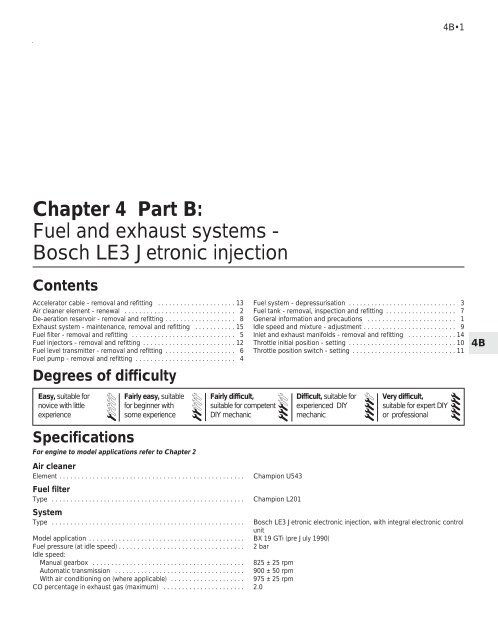
Chapter 4 Part B: Fuel and exhaust systems - Bosch LE3 Jetronic ...
Chapter 4 Part B: Fuel and exhaust systems - Bosch LE3 Jetronic ...
Chapter 4 Part B: Fuel and exhaust systems - Bosch LE3 Jetronic ...
You also want an ePaper? Increase the reach of your titles
YUMPU automatically turns print PDFs into web optimized ePapers that Google loves.
4B•1<br />
<strong>Chapter</strong> 4 <strong>Part</strong> B:<br />
<strong>Fuel</strong> <strong>and</strong> <strong>exhaust</strong> <strong>systems</strong> -<br />
<strong>Bosch</strong> <strong>LE3</strong> <strong>Jetronic</strong> injection<br />
Contents<br />
Accelerator cable - removal <strong>and</strong> refitting . . . . . . . . . . . . . . . . . . . . . 13<br />
Air cleaner element - renewal . . . . . . . . . . . . . . . . . . . . . . . . . . . . . . 2<br />
De-aeration reservoir - removal <strong>and</strong> refitting . . . . . . . . . . . . . . . . . . . 8<br />
Exhaust system - maintenance, removal <strong>and</strong> refitting . . . . . . . . . . . 15<br />
<strong>Fuel</strong> filter - removal <strong>and</strong> refitting . . . . . . . . . . . . . . . . . . . . . . . . . . . . 5<br />
<strong>Fuel</strong> injectors - removal <strong>and</strong> refitting . . . . . . . . . . . . . . . . . . . . . . . . . 12<br />
<strong>Fuel</strong> level transmitter - removal <strong>and</strong> refitting . . . . . . . . . . . . . . . . . . . 6<br />
<strong>Fuel</strong> pump - removal <strong>and</strong> refitting . . . . . . . . . . . . . . . . . . . . . . . . . . . 4<br />
Degrees of difficulty<br />
Easy, suitable for<br />
novice with little<br />
experience<br />
1<br />
Specifications<br />
Fairly easy, suitable<br />
for beginner with<br />
some experience<br />
For engine to model applications refer to <strong>Chapter</strong> 2<br />
Air cleaner<br />
Element . . . . . . . . . . . . . . . . . . . . . . . . . . . . . . . . . . . . . . . . . . . . . . . . . .<br />
<strong>Fuel</strong> filter<br />
Type . . . . . . . . . . . . . . . . . . . . . . . . . . . . . . . . . . . . . . . . . . . . . . . . . . . .<br />
System<br />
Type . . . . . . . . . . . . . . . . . . . . . . . . . . . . . . . . . . . . . . . . . . . . . . . . . . . .<br />
Champion U543<br />
Champion L201<br />
Model application . . . . . . . . . . . . . . . . . . . . . . . . . . . . . . . . . . . . . . . . . . BX 19 GTi (pre July 1990)<br />
<strong>Fuel</strong> pressure (at idle speed) . . . . . . . . . . . . . . . . . . . . . . . . . . . . . . . . . . 2 bar<br />
Idle speed:<br />
Manual gearbox . . . . . . . . . . . . . . . . . . . . . . . . . . . . . . . . . . . . . . . . . 825 ± 25 rpm<br />
Automatic transmission . . . . . . . . . . . . . . . . . . . . . . . . . . . . . . . . . . . 900 ± 50 rpm<br />
With air conditioning on (where applicable) . . . . . . . . . . . . . . . . . . . . 975 ± 25 rpm<br />
CO percentage in <strong>exhaust</strong> gas (maximum) . . . . . . . . . . . . . . . . . . . . . . 2.0<br />
2<br />
Fairly difficult,<br />
suitable for competent<br />
DIY mechanic<br />
<strong>Fuel</strong> system - depressurisation . . . . . . . . . . . . . . . . . . . . . . . . . . . . . 3<br />
<strong>Fuel</strong> tank - removal, inspection <strong>and</strong> refitting . . . . . . . . . . . . . . . . . . . 7<br />
General information <strong>and</strong> precautions . . . . . . . . . . . . . . . . . . . . . . . . 1<br />
Idle speed <strong>and</strong> mixture - adjustment . . . . . . . . . . . . . . . . . . . . . . . . . 9<br />
Inlet <strong>and</strong> <strong>exhaust</strong> manifolds - removal <strong>and</strong> refitting . . . . . . . . . . . . . 14<br />
Throttle initial position - setting . . . . . . . . . . . . . . . . . . . . . . . . . . . . . 10<br />
Throttle position switch - setting . . . . . . . . . . . . . . . . . . . . . . . . . . . . 11<br />
3<br />
Difficult, suitable for<br />
experienced DIY<br />
mechanic<br />
Very difficult,<br />
suitable for expert DIY<br />
or professional<br />
<strong>Bosch</strong> <strong>LE3</strong> <strong>Jetronic</strong> electronic injection, with integral electronic control<br />
unit<br />
4<br />
5<br />
4B
4B•2 <strong>Fuel</strong> <strong>and</strong> <strong>exhaust</strong> <strong>systems</strong> - <strong>Bosch</strong> <strong>LE3</strong> <strong>Jetronic</strong> injection<br />
1.1 <strong>Bosch</strong> <strong>LE3</strong> <strong>Jetronic</strong> fuel injection system components<br />
1 General information <strong>and</strong><br />
precautions<br />
General information<br />
Operation of the <strong>Bosch</strong> <strong>LE3</strong> <strong>Jetronic</strong> fuel<br />
injection system is as follows. A roller-type<br />
electric fuel pump draws fuel from the tank<br />
<strong>and</strong> pumps it through a filter to the injectors<br />
via a distribution pipe. The electronic control<br />
unit, which is triggered by the ignition circuit,<br />
sends impulses to the injectors, which<br />
operate simultaneously <strong>and</strong> inject fuel in the<br />
vicinity of the inlet valves. The electronic<br />
control unit is provided with sensors to<br />
determine engine temperature, speed <strong>and</strong><br />
load, <strong>and</strong> the quantity of air entering the<br />
engine. This information is computed to<br />
determine the period of injection (see<br />
illustration).<br />
For cold starting, additional air is provided<br />
by a supplementary air device. This excess air<br />
“tricks” the system into providing more fuel.<br />
A fuel vapour recirculation system is<br />
integrated into the fuel system (see<br />
illustration). The fuel tank is vented via the<br />
charcoal filter canister. When the engine is<br />
started, any fuel vapour in the de-aerating<br />
reservoir <strong>and</strong> charcoal canister is drawn<br />
through the airflow meter <strong>and</strong> into the throttle<br />
housing by the normal induction method, it is<br />
then burnt in the engine.<br />
Precautions<br />
<strong>Fuel</strong> warning<br />
Many of the procedures in this <strong>Chapter</strong><br />
require the removal of fuel lines <strong>and</strong><br />
1.3 <strong>Fuel</strong> vapour recirculation system<br />
connections which may result in some fuel<br />
spillage. Before carrying out any operation on<br />
the fuel system refer to the precautions given<br />
in Safety first! at the beginning of this Manual<br />
<strong>and</strong> follow them implicitly. Petrol is a highly<br />
dangerous <strong>and</strong> volatile liquid <strong>and</strong> the<br />
precautions necessary when h<strong>and</strong>ling it<br />
cannot be overstressed.<br />
1 <strong>Fuel</strong> tank<br />
2 <strong>Fuel</strong> tank filler<br />
3 De-aeration<br />
reservoir<br />
4 Charcoal canister<br />
5 Airflow meter<br />
(throttle butterfly<br />
housing)
<strong>Fuel</strong> <strong>and</strong> <strong>exhaust</strong> <strong>systems</strong> - <strong>Bosch</strong> <strong>LE3</strong> <strong>Jetronic</strong> injection 4B•3<br />
4.4 <strong>Fuel</strong> pump (1), fuel filter (2), insulator (3) <strong>and</strong> heat shield (4)<br />
pivoted towards centre for removal<br />
4.5 <strong>Fuel</strong> pump wiring connections<br />
System maintenance<br />
Residual fuel pressure will remain in the<br />
system lines long after the vehicle is used.<br />
Before disconnecting any fuel line,<br />
depressurise the fuel system.<br />
In order to prevent damage to the electrical<br />
components of the system, observe the<br />
following precautions:<br />
a) Never disconnect the battery with the<br />
engine running<br />
b) Never disconnect the electronic control<br />
unit with the ignition on<br />
c) Never use a test light for checking system<br />
circuits<br />
Tamperproof adjustment screws<br />
Certain adjustment points in the fuel system<br />
are protected by “tamperproof” caps, plugs or<br />
seals. The purpose of such tamperproofing is<br />
to discourage, <strong>and</strong> to detect, adjustment by<br />
unqualified operators.<br />
In some EEC countries (though not yet in<br />
the UK), it is an offence to drive a vehicle with<br />
missing or broken tamperproof seals. Before<br />
disturbing a seal, satisfy yourself that you will<br />
not be breaking local or national anti-pollution<br />
regulations by doing so. Fit a new seal when<br />
adjustment is complete, when this is required<br />
by law.<br />
Do not break tamperproof seals on a<br />
vehicle which is still under warranty.<br />
Unleaded petrol - usage<br />
Models equipped with the <strong>Bosch</strong> <strong>LE3</strong><br />
<strong>Jetronic</strong> injection system should be run on 97<br />
RON leaded petrol only. However, it is<br />
possible to run on 95 RON unleaded fuel if<br />
suitable adjustments are first carried out.<br />
Consult your Citroën dealer for further<br />
information. Note that the use of unleaded fuel<br />
in a vehicle not suitably adjusted will lead to<br />
serious damage of the valve seats.<br />
2 Air cleaner element - renewal<br />
Refer to <strong>Chapter</strong> 1, Section 28.<br />
1<br />
3 <strong>Fuel</strong> system -<br />
depressurisation 2<br />
Note: Depressurise the fuel system before<br />
carrying out any work on its component parts<br />
Warning: The following procedure<br />
will merely relieve the<br />
pressure in the fuel system.<br />
Remember that fuel will still be<br />
present in system components, so take<br />
precautions accordingly before disconnecting<br />
them<br />
1 The fuel system is defined as the fuel pump,<br />
filter, injectors <strong>and</strong> pressure regulator, also<br />
the metal pipes <strong>and</strong> flexible hoses of the lines<br />
between these components. All these<br />
components contain fuel which will be under<br />
pressure while the engine is running <strong>and</strong>/or<br />
while the ignition is switched on. Pressure will<br />
remain for some time after the ignition has<br />
been switched off <strong>and</strong> must be released<br />
before any of these components are disturbed<br />
for servicing work. Proceed as follows:<br />
2 Disconnect the battery earth lead.<br />
3 Place a suitable container beneath the<br />
relevant union to be disconnected <strong>and</strong> have a<br />
large rag ready to soak up any escaping fuel<br />
not being caught by the container.<br />
4 Slowly loosen the union to avoid a sudden<br />
release of pressure <strong>and</strong> position the rag<br />
around the connection to catch any fuel spray<br />
which may be expelled.<br />
5 Once pressure is released, disconnect the<br />
union <strong>and</strong> insert plugs into its open ends to<br />
minimise fuel loss <strong>and</strong> to prevent the entry of<br />
contamination into the system.<br />
4 <strong>Fuel</strong> pump - removal <strong>and</strong><br />
refitting 3<br />
Removal<br />
1 The fuel pump is located on the underside<br />
of the vehicle, at the rear on the right-h<strong>and</strong><br />
side, just to the rear of the fuel tank. The<br />
pump unit is housed in a rubber insulator,<br />
together with the fuel filter unit which is<br />
located directly above it.<br />
2 For access to the pump (<strong>and</strong>/or filter), raise<br />
<strong>and</strong> support the vehicle at the rear.<br />
3 Disconnect the battery earth lead.<br />
4 Unclip <strong>and</strong> swing the heat shield, insulator,<br />
pump <strong>and</strong> filter units towards the centre (see<br />
illustration).<br />
5 Pull back the rubber protective gaiter from<br />
the end of the fuel pump <strong>and</strong> then detach the<br />
wiring connectors. Note that, whilst both<br />
wires are yellow, one has a white connector<br />
sleeve for identification. Note which has the<br />
sleeve <strong>and</strong> its connection (see illustration).<br />
6 Bearing in mind the information given on<br />
depressurising the fuel system, loosen the<br />
clips <strong>and</strong> remove the fuel lines from the front<br />
<strong>and</strong> rear of the pump unit.<br />
7 Carefully pull <strong>and</strong> withdraw the pump unit<br />
from the insulator.<br />
Refitting<br />
8 Refitting is a reversal of the removal<br />
procedure. Ensure that all connections are<br />
correctly <strong>and</strong> securely made. On completion,<br />
check for satisfactory operation, <strong>and</strong> for any<br />
signs of fuel leaks from the pump<br />
connections.<br />
5 <strong>Fuel</strong> filter - removal <strong>and</strong><br />
refitting 2<br />
Refer to <strong>Chapter</strong> 1, Section 36.<br />
4B
4B•4 <strong>Fuel</strong> <strong>and</strong> <strong>exhaust</strong> <strong>systems</strong> - <strong>Bosch</strong> <strong>LE3</strong> <strong>Jetronic</strong> injection<br />
6 <strong>Fuel</strong> level transmitter -<br />
removal <strong>and</strong> refitting 2<br />
Refer to Section 9 in <strong>Part</strong> A of this <strong>Chapter</strong>.<br />
7 <strong>Fuel</strong> tank - removal,<br />
inspection <strong>and</strong> refitting 3<br />
The fuel tank is of similar design to that<br />
fitted to carburettor models.<br />
Note the information given for<br />
depressurising the fuel system when<br />
disconnecting the tank fuel lines (see<br />
illustration) before following the procedure<br />
given in Section 10 in <strong>Part</strong> A of this <strong>Chapter</strong>.<br />
8 De-aeration reservoir -<br />
removal <strong>and</strong> refitting 2<br />
Removal<br />
1 The de-aeration reservoir is located at the<br />
rear of the car, under the right-h<strong>and</strong> rear<br />
wheel arch (see illustration). It is connected<br />
to the fuel filler pipe <strong>and</strong> the charcoal filter<br />
canister, their function being to vent the fuel<br />
tank. Any fuel vapour stored in them is drawn<br />
into the throttle housing when the engine is<br />
started.<br />
8.1 De-aeration reservoir location - GTi<br />
7.2 <strong>Fuel</strong> tank supply <strong>and</strong> return hoses -<br />
GTi<br />
2 If removing the de-aeration reservoir, take<br />
the same precautions as those mentioned for<br />
fuel tank removal. Detach the hoses from the<br />
reservoir, undo the retaining strap <strong>and</strong><br />
mounting bolts, then lower <strong>and</strong> remove it (see<br />
illustration).<br />
3 A vent valve is also fitted <strong>and</strong> is located<br />
near the de-aeration reservoir. This can be<br />
removed by detaching the hoses <strong>and</strong><br />
unclipping the valve (see illustration).<br />
Refitting<br />
4 Refitting is a reversal of the removal<br />
procedure. Renew any hoses or clips as<br />
necessary <strong>and</strong> check for leakage <strong>and</strong> security<br />
on completion.<br />
9 Idle speed <strong>and</strong> mixture -<br />
adjustment 3<br />
1 Before making any adjustments to the fuel<br />
system, the following conditions must be met:<br />
a) The ignition system must be in good<br />
condition <strong>and</strong> correctly adjusted<br />
b) The air cleaner element must be clean<br />
c) The throttle initial position must be<br />
correctly set, as must the throttle butterfly<br />
spindle switch<br />
d) The engine must be at its normal<br />
operating temperature, the cooling fan<br />
having cut in <strong>and</strong> then out<br />
Idle speed adjustment<br />
2 Refer to <strong>Chapter</strong> 1, Section 23.<br />
Mixture adjustment<br />
3 To adjust the mixture setting, you will need<br />
to punch a hole in the tamperproof plug over<br />
the mixture screw <strong>and</strong> prise out the plug. Turn<br />
the mixture adjustment screw to give a<br />
maximum CO reading of 2.0%. If required,<br />
readjust the idle speed as described<br />
previously (see illustration).<br />
4 Recheck the CO reading <strong>and</strong> readjust the<br />
mixture setting <strong>and</strong> idle speed settings as<br />
necessary.<br />
5 On completion, a new tamperproof plug<br />
should be fitted over the mixture screw.<br />
Disconnect the tachometer <strong>and</strong> the <strong>exhaust</strong><br />
gas analyser to complete.<br />
10 Throttle initial position -<br />
setting<br />
2<br />
Note: This is not a routine adjustment. It<br />
should only be necessary if new components<br />
have been fitted, or if the setting has been<br />
accidentally disturbed.<br />
1 Remove the tamperproof plug from the<br />
throttle butterfly stop screw (located on the<br />
other side of the throttle housing from the idle<br />
speed adjuster screw).<br />
2 Unscrew the throttle butterfly stop screw<br />
until it is no longer in contact with its stop <strong>and</strong><br />
the butterfly is fully closed. Screw it in again<br />
until it just contacts the stop. From this<br />
position, screw it in exactly one quarter of a<br />
turn.<br />
3 Fit a new tamperproof plug, when required.<br />
4 Check the throttle butterfly switch setting.<br />
11 Throttle position switch -<br />
setting<br />
3<br />
1 Disconnect the multi-plug from the throttle<br />
position switch. Connect an ohmmeter or<br />
continuity tester between switch terminals 2<br />
<strong>and</strong> 18.<br />
2 Insert a 0.30 mm feeler blade between the<br />
butterfly stop screw <strong>and</strong> its stop.<br />
3 Slacken the switch mounting screws. Turn<br />
the switch in either direction until the contacts<br />
8.2 De-aeration reservoir retaining strap<br />
<strong>and</strong> mounting bolt (arrowed)<br />
8.3 Vent valve location (arrowed) - GTi 9.3 Mixture adjustment screw (arrowed)
<strong>Fuel</strong> <strong>and</strong> <strong>exhaust</strong> <strong>systems</strong> - <strong>Bosch</strong> <strong>LE3</strong> <strong>Jetronic</strong> injection 4B•5<br />
12.2 Disconnecting a fuel injector wiring connector 12.3a Prising fuel rail free from injectors<br />
are just closed (continuity or zero resistance).<br />
Tighten the screws in this position.<br />
4 Remove the feeler blade <strong>and</strong> insert another<br />
of 0.70 mm thickness. With this blade<br />
inserted, the contacts must be open (no<br />
continuity, or infinite resistance). If not, repeat<br />
the adjustment. Remove the feeler blade.<br />
5 Transfer the ohmmeter to terminals 3 <strong>and</strong><br />
18. Have an assistant depress the throttle<br />
pedal to the floor. At full-throttle, the contacts<br />
must be closed.<br />
6 Disconnect the test equipment <strong>and</strong><br />
reconnect the multi-plug.<br />
12.3b <strong>Fuel</strong> rail/injector clip<br />
12 <strong>Fuel</strong> injectors - removal <strong>and</strong><br />
refitting<br />
3<br />
Removal<br />
1 Disconnect the battery earth lead.<br />
2 Detach the wiring connections from the<br />
injectors by prising open the wire retaining<br />
clip in the connector (see illustration).<br />
3 Prise free the injector-to-fuel supply rail<br />
(tube) retaining clip, using a screwdriver as a<br />
lever (see illustrations).<br />
4 Bearing in mind the information given on<br />
depressurising the fuel system, undo the<br />
retaining bolts <strong>and</strong> remove the fuel supply rail.<br />
The hoses <strong>and</strong> pressure regulator can be left<br />
attached (see illustrations).<br />
5 Withdraw the injectors. Ensure that no<br />
contamination is allowed to enter the fuel<br />
system whilst disconnected.<br />
Refitting<br />
6 Refitting is a reversal of the removal<br />
procedure. Use new injector seals. To ease<br />
fitting of the injectors to their cylinder head<br />
ports, lubricate the seals with a small amount<br />
of soapy solution. Check for signs of fuel<br />
leakage on completion.<br />
13 Accelerator cable - removal<br />
<strong>and</strong> refitting<br />
2<br />
This procedure is similar to that described<br />
in Section 23 in <strong>Part</strong> A of this <strong>Chapter</strong>.<br />
However, the cable connection to the throttle<br />
housing differs (see illustration).<br />
Cable adjustment is the same as for the<br />
carburettor type. Whenever the cable has<br />
been disturbed, check the idle speed.<br />
14 Inlet <strong>and</strong> <strong>exhaust</strong> manifolds -<br />
removal <strong>and</strong> refitting<br />
3<br />
1 The basic procedures are much the same<br />
as those given in <strong>Part</strong> A of this <strong>Chapter</strong>.<br />
2 When removing the inlet manifold, items<br />
such as the injectors <strong>and</strong> ignition coil will need<br />
to be detached. The manifold can either be<br />
removed together with, or separate from, the<br />
throttle housing. Disconnect as appropriate<br />
but note the hose connections.<br />
3 Always use new gaskets when refitting.<br />
4B<br />
12.4a <strong>Fuel</strong> supply rail retaining bolt<br />
(arrowed)<br />
12.4b Pressure regulator attached to fuel<br />
rail<br />
13.1 Accelerator cable adjustment ferrule<br />
(arrowed)
4B•6 <strong>Fuel</strong> <strong>and</strong> <strong>exhaust</strong> <strong>systems</strong> - <strong>Bosch</strong> <strong>LE3</strong> <strong>Jetronic</strong> injection<br />
15 Exhaust system -<br />
maintenance, removal <strong>and</strong><br />
refitting<br />
2<br />
Note the information given in <strong>Part</strong> A of this<br />
<strong>Chapter</strong>. The <strong>exhaust</strong> system fitted to fuel<br />
injection models differs from that fitted to<br />
carburettor models, the main difference being<br />
that the front pipe section incorporates an<br />
expansion chamber. All other components in<br />
the system are also specific to model type<br />
<strong>and</strong> this must be considered when ordering<br />
replacement parts (see illustration).<br />
15.1 Exhaust system - BX 19 GTi


