A touch of Class, The Windom and the J-POLE
A touch of Class, The Windom and the J-POLE
A touch of Class, The Windom and the J-POLE

You also want an ePaper? Increase the reach of your titles
YUMPU automatically turns print PDFs into web optimized ePapers that Google loves.
Serving HAM Radio since 1959, On <strong>the</strong> Web Since 1995<br />
Order Toll Free Monday through Friday, 9 am to 5 pm, 1 800 726 2919 or 1 866 300 1969, All Times, Eastern<br />
NO MINIMUM ORDERS, Same Day Shipping, except Sunday <strong>and</strong> Holidays BUXCOMM Corporation 115<br />
LUENBURG DRIVE EVINGTON, VIRGINIA 24550<br />
BUXCOMM Tech Support is by expert ARO's, Technicians <strong>and</strong> Engineers. *Tech Support; Email; support@buxcomm.com<br />
A <strong>touch</strong> <strong>of</strong> <strong>Class</strong>, <strong>The</strong> <strong>Windom</strong> <strong>and</strong> <strong>the</strong> J-<strong>POLE</strong><br />
By Glynn E. "Buck" Rogers Sr (68 years as K4ABT)<br />
<strong>The</strong> J-<strong>POLE</strong> has been around since <strong>the</strong> early days <strong>of</strong> HAM Radio, <strong>and</strong> is a direct descendant <strong>of</strong> <strong>the</strong> "<strong>Windom</strong>"<br />
Like <strong>the</strong> <strong>Windom</strong> or ZEPP, <strong>the</strong> J-<strong>POLE</strong> is a spin-<strong>of</strong>f, or a modified WINDOM for VHF <strong>and</strong> UHF. One <strong>of</strong> <strong>the</strong><br />
first articles I wrote about <strong>the</strong> J-Pole was in HRC magazine in 1958. Since 1958, I've written several j-pole<br />
articles in o<strong>the</strong>r HAM Radio publications.<br />
Here, my references are to <strong>the</strong> early, 1923 (version) <strong>Windom</strong> (Article by Loren G. <strong>Windom</strong> September 1929,<br />
QST magazine) . If you look at <strong>the</strong> feed <strong>of</strong> <strong>the</strong> early <strong>Windom</strong> that was fed with a single wire, you may soon<br />
see <strong>the</strong> similarity between <strong>the</strong> <strong>Windom</strong>, ZEPP, <strong>and</strong> <strong>the</strong> J-Pole.<br />
Look close at <strong>the</strong> configuration <strong>of</strong> <strong>the</strong> Jpole <strong>and</strong> <strong>the</strong> <strong>Windom</strong>, <strong>and</strong> you will underst<strong>and</strong> why in many <strong>of</strong> my<br />
articles in CQ Magazine <strong>and</strong> o<strong>the</strong>r publications, that I <strong>of</strong>ten refer to <strong>the</strong> Jpole as a <strong>Windom</strong>, with <strong>the</strong> short<br />
section folded back on itself to form <strong>the</strong> parasitic element. It is for this reason that I feel <strong>the</strong>se are two <strong>of</strong> <strong>the</strong><br />
best antennas ever designed. Having said this, you will also note that <strong>the</strong> <strong>Windom</strong> (<strong>and</strong> <strong>the</strong> Jpole) are powerful<br />
antennas that provide outst<strong>and</strong>ing performance on all b<strong>and</strong>s above <strong>the</strong> b<strong>and</strong> for which <strong>the</strong>y are cut or designed<br />
for.<br />
<strong>The</strong> reason <strong>the</strong>se two antennas perform so well (as Multi-B<strong>and</strong> antennas; <strong>Windom</strong> for HF & lo VHF, Jpole<br />
VHF & UHF), is because <strong>the</strong>y operate at harmonics <strong>of</strong> <strong>the</strong> fundamental or lowest frequency for which <strong>the</strong>y are<br />
cut/designed. To add additional feeders (ladder-line), o<strong>the</strong>r than 50 ohm coax or UNUNs is a waste <strong>of</strong> RF<br />
energy. Only 50 ohm coaxial cable <strong>and</strong> a BALUN at <strong>the</strong> feed-point is all that is necessary. Anything more,<br />
adds losses into <strong>the</strong> equation that cannot be overcome after-<strong>the</strong>-fact.<br />
Remember <strong>the</strong> axiom:<br />
"When you have reached perfection, anything more becomes a point <strong>of</strong> diminishing returns." Enough said!<br />
Trust me on <strong>the</strong> above paragraph, as I have experimented with every <strong>Windom</strong> <strong>and</strong> Jpole concept or design that<br />
can be imagined. Having built <strong>and</strong> sold thous<strong>and</strong>s <strong>of</strong> <strong>the</strong>se two antennas, I've found that It's difficult to improve<br />
on perfection.
For now, let's look at some <strong>of</strong> <strong>the</strong> features <strong>of</strong> our J-Pole, whe<strong>the</strong>r for; 140-150 mHz, or 430-450 mHz<br />
<strong>the</strong> J-Pole is easy to erect<br />
<strong>the</strong> J-Pole needs no radials<br />
<strong>the</strong> J-Pole has low angle radiation<br />
<strong>the</strong> J-<strong>POLE</strong> has greater b<strong>and</strong>width.<br />
<strong>the</strong> J-Pole has greater immunity to terrestrial noise<br />
<strong>the</strong> J-Pole is great for local nets or distant repeaters<br />
<strong>the</strong> J-Pole has more gain than most Ground Planes<br />
<strong>the</strong> J-Pole is more durable than most Ground Planes<br />
<strong>the</strong> J-Pole meets most "stealth" antenna restriction agreements<br />
<strong>the</strong> J-Pole has less static-charge noise, <strong>and</strong> static-charge build-up.<br />
In <strong>the</strong> mid-fifties, <strong>and</strong> early sixties, ridged copper was difficult to find, <strong>and</strong> even if we were fortunate<br />
enough to locate ridged copper, <strong>the</strong> cost was prohibitive. Most <strong>of</strong> our VHF (don't even think about UHF)<br />
operating was AM (for <strong>the</strong> late model HAM, "Amplitude Modulation"), <strong>and</strong> on two meters, operating was<br />
centered around 144 MHz. We ei<strong>the</strong>r opt'd for a bamboo spreader cubical quad, or folded "zepp," as we<br />
called it in those days (now-a-days, called a "J-Pole.")<br />
Ano<strong>the</strong>r variation to this antenna construction was to use electrical thin-wall conduit or "EMT." EMT actually<br />
means "electrical metallic thin-wall" but somehow early acronyms had a way <strong>of</strong> getting turned around, or inverted,<br />
. . . or perverted.. hi.<br />
Using metal EMT instead <strong>of</strong> copper, we learned to use <strong>the</strong> brazing rods <strong>and</strong> torch to fabricate our "folded (zepp) Jay."<br />
In any case, we were able to make <strong>the</strong> J-Pole happen. For VHF, <strong>the</strong> J-Pole became <strong>the</strong> antenna <strong>of</strong> choice,<br />
just as <strong>the</strong> <strong>Windom</strong> took its place as <strong>the</strong> antenna <strong>of</strong> choice for <strong>the</strong> lower (HF) b<strong>and</strong>s. As a matter <strong>of</strong> interest,<br />
look close at both <strong>the</strong> J-pole <strong>and</strong> <strong>the</strong> <strong>Windom</strong>, <strong>and</strong> you might find a close resemblance <strong>and</strong> maybe even some<br />
relationships in <strong>the</strong> <strong>of</strong>f-center method used to feed each <strong>of</strong> <strong>the</strong>m.<br />
I've heard <strong>of</strong> J-poles stacked, collinearized, <strong>and</strong> some with weird fitted, 1955 Ford fender-skirts. Depending on<br />
who's telling <strong>the</strong> story, <strong>the</strong>y might have more gain than a yagi on a helicopter at 1200 feet, or <strong>the</strong>y won't reach a h<strong>and</strong>-held<br />
across <strong>the</strong> backyard. I try to make it a personal point to stay out <strong>of</strong> <strong>the</strong>se CB<br />
University fences. You can put a "mini-skirt" on it, you can even place a "tutu" on<br />
<strong>the</strong> J-Pole, but <strong>the</strong> truth is, it remains a Jpole.<br />
As a personal observation throughout my 64 years as a HAM; Mistakes,<br />
Experience, <strong>and</strong> Knowledge has given this ole HAM <strong>the</strong> Wisdom to know <strong>the</strong><br />
difference. Don't try to build a <strong>Windom</strong> for two meters, <strong>and</strong> for<br />
heavens sake, DO NOT attempt building a J-Pole for seventy-five (75) meters.<br />
As <strong>the</strong>y say, "do <strong>the</strong> math;" Just <strong>the</strong> long, vertical section <strong>of</strong> a 75 meter J-pole<br />
would near 200 feet.<br />
TO THE POINT OF OUR SUBJECT:<br />
I've had many requests for a ready-made J-pole design that will enable <strong>the</strong> Amateur<br />
Radio user to print <strong>the</strong> image from a web page <strong>and</strong> go directly to <strong>the</strong> construction<br />
table <strong>and</strong> build a J-Pole antenna for <strong>the</strong>ir HAM Radio station.<br />
On this page you will find many illustrations I've drawn to help you underst<strong>and</strong> <strong>the</strong><br />
manner in which a J Pole is built.<br />
Fabrication can sometimes be a problem for <strong>the</strong> apartment dweller, or <strong>the</strong> HAM<br />
with limited facilities for this kind <strong>of</strong> project.<br />
For <strong>the</strong>se reasons, you may wish to purchase <strong>the</strong> "direct fed Jpole"<br />
ready to install. We <strong>of</strong>fer this BUXCOMM J POL<br />
in two versions;
A VARIATION ON A THEME:<br />
Let's look first at FIGURE 1a; This is <strong>the</strong> overview <strong>and</strong> pr<strong>of</strong>ile <strong>of</strong> <strong>the</strong> J-Pole we will be working with. <strong>The</strong>re are two different b<strong>and</strong>s<br />
we will be building <strong>the</strong> J-Pole antennas for. NO, we will not build a two b<strong>and</strong> antenna on one mast. I've been <strong>the</strong>re, done that.. <strong>and</strong> it<br />
is an exercise in futility.<br />
For openers, I would like to show you that all J-poles are not created equal. By that statement; I mean, we will modify our<br />
construction techniques a bit <strong>and</strong> apply a variation to <strong>the</strong> <strong>the</strong>me. Notice in <strong>the</strong> exploded view at FIGURE 1b, I've deviated from <strong>the</strong><br />
usual RF feed technique that we normally use to attach our coaxial cable to <strong>the</strong> J-pole.<br />
Where we usually attach <strong>the</strong> shield <strong>and</strong> center conductor to <strong>the</strong> tuning stub <strong>and</strong> <strong>the</strong> driven element with aero-seal (hose) clamps, here<br />
we've made a slight change in <strong>the</strong> design by exchanging <strong>the</strong> elbow for a tee. Below <strong>the</strong> short (1/4 wave tuning stub) section, we<br />
(carefully) soldered an SO-239 (Chassi-mount) coax (female) connector.<br />
But notice that we must first attach a piece <strong>of</strong> number 12 or 14 insulated, copper wire to <strong>the</strong> SO-239. <strong>The</strong> length <strong>of</strong> this wire<br />
depends on <strong>the</strong> spacing between <strong>the</strong> stub <strong>and</strong> (Fig 1A "D") long section <strong>of</strong> our antenna.<br />
If <strong>the</strong> antenna is for six meters, <strong>the</strong> wire length will need to be about, 10 to 12 inches long. If our antenna is for two meters, <strong>the</strong> wire<br />
length will be less than 8 inches overall.<br />
I am careful when I (Benz-O-Matic torch) solder <strong>the</strong> SO-239 to <strong>the</strong> copper tee, since I don't want to heat <strong>the</strong> SO-239 to <strong>the</strong> point <strong>the</strong><br />
solder on <strong>the</strong> wire melts <strong>and</strong> I have to begin <strong>the</strong> process again.<br />
Shown below & above are our direct feed J-Poles.<br />
For 2 meters (145.000 to 146.000 MHz) <strong>the</strong> EXACT dimensions are:<br />
A = 58 inches overall (Long, driven element).<br />
B = 19.5 Inches<br />
C = 2 Inches<br />
D = 1.8 Inches (space)<br />
For 6 meters (50.500 to 51.500 MHz) <strong>the</strong> EXACT dimensions are:<br />
A = 166-3/4 inches overall (long, driven element).<br />
B = 58-3/4 inches (short, tuning stub).<br />
C = 5.5 Inches<br />
D = 5 inches<br />
USE BUX "VBALUN" withJ-Poles 1 kw VHF & UHF<br />
BALUN, BUX VBALUN<br />
> CLICK HERE for on-line CATALOG<br />
Hi-Q, toroid design, wound with teflon covered, silver wire.<br />
For VHF beams, J-Pole matching applications, <strong>and</strong> construction.
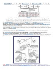
FIGURE 1a<br />
Figure 1b<br />
NOTE: Coax center conductor attaches to <strong>the</strong> "Long section" feed point.<br />
Shield attaches to <strong>the</strong> short section feed point.
USE BUX "VBALUN" withJ-Poles 1 kw VHF Balun, BUX VBALUN<br />
> CLICK HERE for on-line CATALOG<br />
Hi-Q, toroid design, wound with teflon covered, silver wire.<br />
For VHF beams <strong>and</strong> J-Pole matching applications, <strong>and</strong> construction.<br />
An adjustable VSWR, 2 meter J-Pole<br />
BUX VBALUN should be installed at <strong>the</strong> antenna feed point, or where <strong>the</strong> coax or feedline<br />
attaches to <strong>the</strong> J-Pole antenna. BUX BALUNs are used to connect balanced<br />
antennas to unbalanced transmission lines, such as coax cable. <strong>The</strong>ir primary purpose is<br />
to prevent antenna (RF) currents from flowing down <strong>the</strong> outside <strong>of</strong> <strong>the</strong> cable<br />
(VSWR). Ano<strong>the</strong>r function <strong>of</strong> <strong>the</strong> BUX BALUN41 is to match <strong>the</strong> impedance <strong>of</strong> an<br />
unbalanced coax to <strong>the</strong> antenna feed point. BUX LISO BALUNS may also be used as<br />
“line isolators” anywhere along <strong>the</strong> cable to prevent <strong>the</strong> destructive influence <strong>of</strong> induced<br />
RF currents (VSWR). BUX 1:1 BALUNs are current BALUNs. <strong>The</strong>y consist <strong>of</strong> several<br />
large, number 73, ferrite cores.
CLOSE UP <strong>of</strong> <strong>the</strong> alternative coax feed method.<br />
Use BUX VBALUN to couple coaxial cable to J-Pole.<br />
My Hardware J-Poles from 1959 & BUXCOMM J2JAY (1995)<br />
In <strong>the</strong> early days <strong>of</strong> packetRadio, we used this Jpole as an Indoor antenna to<br />
hit <strong>the</strong> local Packet Nodes (PacketRepeater). Unbelievable performance when<br />
suspended vertically near a window or <strong>of</strong>f <strong>the</strong> patio. Gain is 3.7 dbi MOL.
A=Benz-O-Matic propane torch; B=Lead-Free solder; C=Tape measure: D=Tubing cutter; E=Sharpie marking<br />
pen; F=Solder Paste; G=1/2 inch copper caps; H=Hardcopy <strong>of</strong> <strong>the</strong> above drawing; I=Wet Towel; J=PreCut,<br />
ready to assemble parts <strong>of</strong> <strong>the</strong> 2 meter J-Pole.
BUXCOMM J Pole Calculation by BucK4ABT (C) 1992<br />
Center conductor to "Long Element" <strong>and</strong> Shield to "Short Element."<br />
One is for 144 to 148 mHz (model JPOL2) <strong>and</strong> <strong>the</strong> o<strong>the</strong>r is for 430-450 mHz (model JPOL4).<br />
Both models are shown in <strong>the</strong> following illustration:
2 meter version: 144 to 150<br />
mHz<br />
(model JPOL2)<br />
> CLICK HERE for on-line<br />
CATALOG<br />
70cm version: 430-450 mHz<br />
(model JPOL4)<br />
> CLICK HERE for on-line<br />
CATALOG<br />
<strong>The</strong> object is to eliminate <strong>the</strong> need to go through all <strong>the</strong> calculations on ano<strong>the</strong>r page <strong>of</strong> this website.
For all type <strong>of</strong> outdoor antenna<br />
connections, BALUNS, Coax<br />
connectors, coax bulkhead<br />
entry panels <strong>and</strong> more. Use<br />
Coax-Seal® to protect any<br />
outdoor connection or<br />
connector. Coax-Seal is made<br />
<strong>of</strong> a non-conductive, noncontaminating<br />
waterpro<strong>of</strong><br />
material that remains flexible at<br />
any temperature from -30° to<br />
180°F. Coax connectors that<br />
are not waterpro<strong>of</strong> or have<br />
exposed solder joints can<br />
weaken from oxidation ! Coax-<br />
Seal is superior to electrical<br />
tape or vinyl sealants for<br />
moisture protection. Each box<br />
<strong>of</strong> Coax-Seal contains (60<br />
inches x 1/2 inch) five feet <strong>and</strong><br />
will protect ten (10) connectors.<br />
CAT#, CS104, For<br />
all type <strong>of</strong> outdoor<br />
antenna<br />
connections,<br />
BALUNS, Coax<br />
connectors, coax<br />
bulkhead entry<br />
panels <strong>and</strong> more.<br />
Serving HAM Radio since 1959, On <strong>the</strong> Web Since 1992<br />
Order Toll Free Monday through Friday, 9 am to 5 pm, 1 800 726 2919 or 1 866 300 1969, Saturday 9 AM to 2 PM<br />
Eastern Time<br />
NO MINIMUM ORDERS, Same Day Shipping, except Sunday <strong>and</strong> Holidays<br />
BUXCOMM Corporation 115 LUENBURG DRIVE EVINGTON, VIRGINIA 24550<br />
BUXCOMM Tech Support is by expert Technicians <strong>and</strong> Engineers. *Tech Support; Email; support@buxcomm.com<br />
Web Page Design <strong>and</strong> HTML By<br />
G. E. 'Buck' Rogers Sr K4ABT d/b/a BUX CommCo tm ® & © <strong>and</strong> is a trademark <strong>of</strong>; G.E. "Buck" Rogers Sr., Communications Consultants<br />
All text <strong>and</strong> graphics on <strong>the</strong>se pages are ©® <strong>of</strong> G. E. Rogers Sr <strong>and</strong> BUX COMM Corp 1958 - 2011