Set-3 Final by Jahangir (27-36)R.p65 - SIA GROUP
Set-3 Final by Jahangir (27-36)R.p65 - SIA GROUP
Set-3 Final by Jahangir (27-36)R.p65 - SIA GROUP

You also want an ePaper? Increase the reach of your titles
YUMPU automatically turns print PDFs into web optimized ePapers that Google loves.
S.34 Spectrum ALL-IN-ONE Journal for Engineering Students, 2013<br />
as,<br />
Total torque required to turn the hand wheel is given<br />
d ⎛ D 60 ⎞<br />
T = P × + µ cWR<br />
⎜Q R = = = 30 mm ⎟<br />
2 ⎝ 2 2 ⎠<br />
= 23<strong>27</strong> .935×<br />
50<br />
+ (0.18×<br />
10×<br />
10<br />
3 30)<br />
2<br />
×<br />
T = 112.198 × 10 3 N-mm<br />
Torque applied to hand wheel is given as,<br />
D1<br />
T = 2P 1 ×<br />
2<br />
D 1<br />
112.198 × 10 3 = 2×<br />
100×<br />
2<br />
∴<br />
D 1<br />
=<br />
2×<br />
112.198×<br />
10<br />
2×<br />
100<br />
D 1<br />
= 1121.98 ~ 1122 mm<br />
D 1<br />
= 1122 mm or 1.122 m<br />
∴ Diameter of hand wheel is 1.122 m.<br />
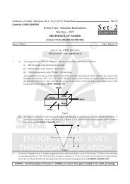
Q7. (a) Explain the following terms of the<br />
spring,<br />
(i) Free length<br />
(ii) Solid height<br />
(iii) Spring rate<br />
(iv) Active and inactive coils<br />
(v) Spring index and<br />
(vi) Stress factor.<br />
Answer :<br />
April/May-12, <strong>Set</strong>-3, Q7(a)<br />
(i) Free Length<br />
It is defined as the total length of helical compressed<br />
spring when it is unloaded. When the spring is loaded or<br />
compressed completely then it is given as,<br />
l f<br />
= Solid length + Maximum deflection + Clearance<br />
between adjacent coils.<br />
Clearance between adjacent coil is usually taken as<br />
0.15 × Maximum deflection.<br />
i.e., 0.15 (δ max<br />
)<br />
∴ l f<br />
= n 1<br />
× d + δ max<br />
+ 0.15 (δ max<br />
)<br />
(ii) Solid Height<br />
When a helical spring is compressed axially along<br />
the helical axis, till the coils comes in contact with each other<br />
then solid length is given as the product of total number of<br />
coils and the diameter of wire. It is denoted <strong>by</strong> l s<br />
.<br />
= n 1<br />
× d<br />
l s<br />
3<br />
(iii) Spring Rate<br />
It is defined as the ratio of applied load to deflection<br />
of spring. It is also known as stiffness or spring constant. It<br />
is denoted <strong>by</strong> ‘k’ and given as,<br />
k = δ<br />
W<br />
Where,<br />
W = Applied load in Newtons<br />
δ = Deflection of spring in mm.<br />
(iv) Active and Inactive Coils<br />
It is defined as the coils which are actively<br />
participating in spring action when the load is applied. In<br />
squared and grounded ends, the bottom most does not<br />
participate in spring action and hence, it is called as inactive<br />
coil. The number of inactive turns increases from the bottom<br />
side as the load increases. The coils other than inactive<br />
coils are known as active number of coils.<br />
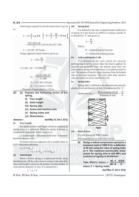
(v) Spring Index<br />
Spring index is defined as the ratio between mean diameter<br />
of coil and diameter of wire. It is represented <strong>by</strong> ‘C’.<br />
(vi)<br />
Mathematically, C =<br />
D<br />
Mean diameter of coil<br />
Diameter of wire<br />
d<br />
=<br />
D<br />
d<br />
Figure<br />
Stress Factor<br />
It is also known as Wahl’s factor.<br />
For remaining answer refer Unit-VII, Q5.<br />
(b) Design a helical compression spring for a<br />
maximum load of 1000 N for a deflection<br />
of 25 mm using the value of spring index<br />
as 5. The maximum permissible shear<br />
stress for spring wire is 420 MPa and<br />
modulus of rigidity is 84 kN/mm 2 .<br />
4C -1 0.615<br />
Take Wahl’s factor = +<br />
4C - 4 C ,<br />
where C = Spring index.<br />
April/May-12, <strong>Set</strong>-3, Q7(b)<br />
B.Tech. III-Year II-Sem.<br />
( JNTU-Anantapur)
![Set-2 Final by Mudassir [10-22] N.p65 - SIA GROUP](https://img.yumpu.com/50708500/1/184x260/set-2-final-by-mudassir-10-22-np65-sia-group.jpg?quality=85)
![Set-1 Final by Mudassir [1-4].p65 - SIA GROUP](https://img.yumpu.com/49027305/1/184x260/set-1-final-by-mudassir-1-4p65-sia-group.jpg?quality=85)
![Set-1 Final by Mudassir [1-16] (M).p65 - SIA GROUP](https://img.yumpu.com/36090047/1/184x260/set-1-final-by-mudassir-1-16-mp65-sia-group.jpg?quality=85)