Set-1 Final by Nazeef (8) (M).p65 - SIA GROUP
Set-1 Final by Nazeef (8) (M).p65 - SIA GROUP
Set-1 Final by Nazeef (8) (M).p65 - SIA GROUP

You also want an ePaper? Increase the reach of your titles
YUMPU automatically turns print PDFs into web optimized ePapers that Google loves.
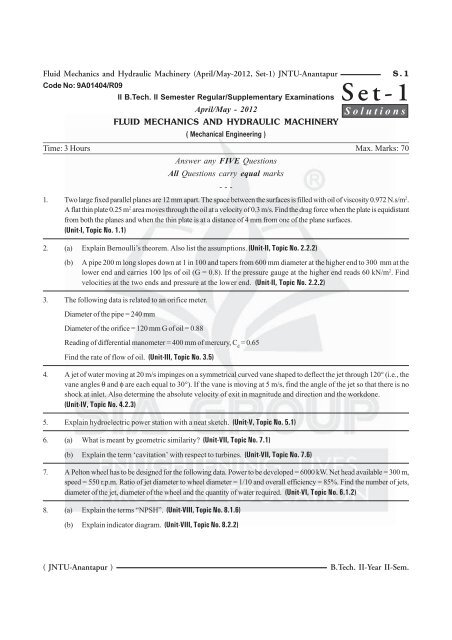
Fluid Mechanics and Hydraulic Machinery (April/May-2012, <strong>Set</strong>-1) JNTU-Anantapur<br />
Code No: 9A01404/R09<br />
II B.Tech. II Semester Regular/Supplementary Examinations<br />
April/May - 2012<br />
FLUID MECHANICS AND HYDRAULIC MACHINERY<br />
( Mechanical Engineering )<br />
S.1<br />
Time: 3 Hours Max. Marks: 70<br />
Answer any FIVE Questions<br />
All Questions carry equal marks<br />
- - -<br />
1. Two large fixed parallel planes are 12 mm apart. The space between the surfaces is filled with oil of viscosity 0.972 N.s/m 2 .<br />
A flat thin plate 0.25 m 2 area moves through the oil at a velocity of 0.3 m/s. Find the drag force when the plate is equidistant<br />
from both the planes and when the thin plate is at a distance of 4 mm from one of the plane surfaces.<br />
(Unit-I, Topic No. 1.1)<br />
2. (a) Explain Bernoulli’s theorem. Also list the assumptions. (Unit-II, Topic No. 2.2.2)<br />
<strong>Set</strong>-1<br />
Solutions<br />
(b)<br />
A pipe 200 m long slopes down at 1 in 100 and tapers from 600 mm diameter at the higher end to 300 mm at the<br />
lower end and carries 100 lps of oil (G = 0.8). If the pressure gauge at the higher end reads 60 kN/m 2 . Find<br />
velocities at the two ends and pressure at the lower end. (Unit-II, Topic No. 2.2.2)<br />
3. The following data is related to an orifice meter.<br />
Diameter of the pipe = 240 mm<br />
Diameter of the orifice = 120 mm G of oil = 0.88<br />
Reading of differential manometer = 400 mm of mercury, C d<br />
= 0.65<br />
Find the rate of flow of oil. (Unit-III, Topic No. 3.5)<br />
4. A jet of water moving at 20 m/s impinges on a symmetrical curved vane shaped to deflect the jet through 120° (i.e., the<br />
vane angles θ and φ are each equal to 30°). If the vane is moving at 5 m/s, find the angle of the jet so that there is no<br />
shock at inlet. Also determine the absolute velocity of exit in magnitude and direction and the workdone.<br />
(Unit-IV, Topic No. 4.2.3)<br />
5. Explain hydroelectric power station with a neat sketch. (Unit-V, Topic No. 5.1)<br />
6. (a) What is meant <strong>by</strong> geometric similarity (Unit-VII, Topic No. 7.1)<br />
(b) Explain the term ‘cavitation’ with respect to turbines. (Unit-VII, Topic No. 7.6)<br />
7. A Pelton wheel has to be designed for the following data. Power to be developed = 6000 kW. Net head available = 300 m,<br />
speed = 550 r.p.m. Ratio of jet diameter to wheel diameter = 1/10 and overall efficiency = 85%. Find the number of jets,<br />
diameter of the jet, diameter of the wheel and the quantity of water required. (Unit-VI, Topic No. 6.1.2)<br />
8. (a) Explain the terms “NPSH”. (Unit-VIII, Topic No. 8.1.6)<br />
(b) Explain indicator diagram. (Unit-VIII, Topic No. 8.2.2)<br />
( JNTU-Anantapur ) B.Tech. II-Year II-Sem.
S.2 Spectrum ALL-IN-ONE Journal for Engineering Students, 2013<br />
SOLUTIONS TO APRIL/MAY-2012, SET-1, QP<br />
Q1. Two large fixed parallel planes are 12 mm apart. The space between the surfaces is filled with oil<br />
of viscosity 0.972 N.s/m 2 . A flat thin plate 0.25 m 2 area moves through the oil at a velocity of 0.3 m/<br />
s. Find the drag force when the plate is equidistant from both the planes and when the thin plate<br />
is at a distance of 4 mm from one of the plane surfaces.<br />
Answer :<br />
April/May-12, <strong>Set</strong>-1, Q1<br />
Given that,<br />
Distance between fixed parallel planes, x = 12 mm = 0.012 m<br />
Area of thin plate, A = 0.25 m 2<br />
Viscosity of oil, µ = 0.972 Ns/m 2<br />
Velocity of plate, u = 0.3 m/sec<br />
12 mm<br />
6 mm<br />
6 mm<br />
.<br />
.<br />
.<br />
.<br />
.<br />
.<br />
. .<br />
. . .<br />
. .. . . .<br />
. .<br />
. .<br />
. . .<br />
.<br />
. . .<br />
.<br />
. . .<br />
.<br />
.<br />
. . . .<br />
.<br />
1<br />
. . . .<br />
. ..<br />
.<br />
.<br />
. .<br />
..<br />
. .<br />
.<br />
. .<br />
F s1<br />
8 . mm.<br />
. .<br />
. . . . .<br />
.<br />
. . . . .<br />
. . .<br />
. . .<br />
. . . . .<br />
Thin plate<br />
. . .<br />
. . .<br />
. .<br />
. . .<br />
. .<br />
. .<br />
. .. . . . . . . . . . . .<br />
F<br />
.<br />
. . . .<br />
.<br />
2 . . . .<br />
. .<br />
..<br />
. .<br />
0.3 m/sec<br />
. .<br />
. . . . . . . .<br />
.<br />
.<br />
.<br />
. .<br />
. . .<br />
. .<br />
. . . .<br />
..<br />
. .<br />
. . .<br />
.<br />
. . . . .<br />
.<br />
. . . . .<br />
. . 0.3 m/sec<br />
4 mm . .<br />
. .<br />
.<br />
. .<br />
.<br />
.<br />
F s2<br />
Figure<br />
Case (i)<br />
When the plate is equidistant from both the planes.<br />
Let,<br />
F s 1<br />
and s2<br />
F be the shear force acting on the top and bottom side of the plate as shown in the figure.<br />
Resultant force required to drag the plate, F = F s + F<br />
1 s 2<br />
Change in velocity, du = u – 0 = 0.3 – 0<br />
= 0.3 m/sec<br />
Distance between top plane and thin plate, dy = 6 mm = 0.006 m<br />
Shear force can be calculated <strong>by</strong> using following equation,<br />
⎛ du⎞<br />
⎛ 0.3 ⎞<br />
τ 1<br />
= µ<br />
⎜<br />
⎟ = 0.972⎜<br />
⎟<br />
⎝ dy⎠<br />
⎝ 0.006 ⎠<br />
1<br />
τ 1<br />
= 48.6 N/m 2<br />
Therefore, shear stress on the top side of thin plate is 48.6 N/m 2 .<br />
Shear force,<br />
B.Tech. II-Year II-Sem.<br />
F s<br />
= τ<br />
1 1<br />
× A<br />
= 48.6 × 0.25<br />
= 12.15 N<br />
( JNTU-Anantapur)
Fluid Mechanics and Hydraulic Machinery (April/May-2012, <strong>Set</strong>-1) JNTU-Anantapur<br />
Similarly, shear stress on bottom side of thin plate is<br />
given <strong>by</strong>,<br />
⎛ du⎞<br />
⎛ 0.3 ⎞<br />
τ 2<br />
= µ<br />
⎜<br />
⎟ = 0.972 × ⎜ ⎟<br />
⎝ dy⎠<br />
⎝ 0.006 ⎠<br />
2<br />
τ 2<br />
= 48.6 Ns/m 2<br />
Shear stress on the bottom side of thin plate is<br />
48.6 Ns/m 2<br />
∴ Shear force, F<br />
s 2<br />
F s 2<br />
Total force, F =<br />
= τ 2<br />
× A<br />
= 48.6 × 0.25<br />
= 12.15 N<br />
F +<br />
s 1<br />
F s2<br />
= 12. 15 + 12.15<br />
F = 24.30 N<br />
Case (ii)<br />
When the thin plate is at a distance of 40 mm from<br />
one of the plane surfaces.<br />
In this case, dy 1<br />
= 8 mm = 0.008 m<br />
dy 2<br />
= 4 mm = 0.00 4 m<br />
Shear force on the top side of thin plate,<br />
F s 1<br />
F s 1<br />
= τ 1<br />
× A<br />
⎛ du⎞<br />
= µ<br />
⎜<br />
⎟ × A<br />
⎝ dy⎠<br />
1<br />
⎛ 0.3 ⎞<br />
= 0.972 × ⎜ ⎟ × 0.25<br />
⎝ 0.008 ⎠<br />
= 9.113 N<br />
Shear force on the bottom side of thin plate,<br />
F s 2<br />
F s 2<br />
Total force,<br />
∴ F =<br />
= τ 2<br />
× A<br />
⎛ 0.3 ⎞<br />
= 0.972 × ⎜ ⎟ × 0.25<br />
⎝ 0.004 ⎠<br />
= 18.225 N<br />
F +<br />
s 1<br />
F s2<br />
= 9.113 + 18.225<br />
S.3<br />
Q2. (a) Explain Bernoulli’s theorem. Also list the<br />
assumptions.<br />
Answer :<br />
April/May-12, <strong>Set</strong>-1, Q2(a)<br />
Bernoulli’s Theorem<br />
For answer refer Unit-II, Q31.<br />
Assumptions of Bernoulli’s Theorem<br />
For answer refer Unit-II, Q32, Topic: Assumptions<br />
made in the Derivation Bernoulli’s Equation.<br />
(b) A pipe 200 m long slopes down at 1 in<br />
100 and tapers from 600 mm diameter<br />
at the higher end to 300 mm at the lower<br />
end and carries 100 lps of oil (G = 0.8).<br />
If the pressure gauge at the higher end<br />
reads 60 kN/m 2 . Find velocities at the<br />
two ends and pressure at the lower end.<br />
Answer :<br />
April/May-12, <strong>Set</strong>-1, Q2(b)<br />
Given that,<br />
F = 27.338 N<br />
( JNTU-Anantapur ) B.Tech. II-Year II-Sem.<br />
2<br />
200 mm<br />
Slope 1 in 100<br />
Z 1<br />
P V 2 , d 2 , Z 2 P 1 , V 1 , d 1 , Z 1<br />
1<br />
Figure<br />
Diameter at higher end, d 1<br />
= 600 mm = 0.6 m<br />
Diameter at lower end, d 2<br />
= 300 mm = 0.3 m<br />
Pressure at higher end, P 1<br />
= 60 kN/m 2<br />
∴ Density of oil, ρ oil<br />
= 0.8<br />
Rate of flow, Q = 100 lps = 0.1 m 3 /sec<br />
Length of pipe = 200 m<br />
Area at higher end,<br />
⇒ a 1<br />
= 4<br />
π (d1 ) 2 = π 4 × (0.6)2<br />
a 1<br />
= 0.283 m 2<br />
Discharge, Q = a 1<br />
V 1<br />
⇒ V 1<br />
=<br />
Q 0.1 =<br />
0. 283<br />
a 1<br />
∴ Velocity at higher end, V1<br />
= 0.353 m/sec
S.4 Spectrum ALL-IN-ONE Journal for Engineering Students, 2013<br />
Answer :<br />
1<br />
Datum head, Z 1<br />
= × 200 = 2 m<br />
Given that,<br />
100<br />
Diameter of pipe, D P<br />
= 240 mm = 0.24 m<br />
Area at lower end, a 2<br />
= π 4 (d 2 )2 = π 4 × Diameter of orifice, D o<br />
= 120 mm = 0.12 m<br />
(0.3)2<br />
Manometer reading, x = 400 mm = 0.4 m<br />
a 2<br />
= 0.071 m 2<br />
Coefficient of discharge, C d<br />
= 0.65<br />
Discharge, Q = a 2<br />
V Specific gravity of oil, S<br />
2<br />
o<br />
= 0.88<br />
Area of pipe cross-section,<br />
Q 0.1<br />
⇒ V 2<br />
= =<br />
0. 071<br />
A p<br />
= π 4 (D p )2 = π 4 (0.24)2<br />
a 2<br />
∴Velocity at lower end, V2 = 1.408m/sec<br />
Datum head, Z 2<br />
= 0 (datum level)<br />
According to Bernoulli’s equation,<br />
2<br />
P 1<br />
ρ g<br />
+ V1<br />
2g<br />
60<br />
+<br />
0.8 × 9.81<br />
+ Z 1<br />
=<br />
P 2<br />
ρg<br />
2<br />
V2<br />
+ + Z<br />
2g<br />
2<br />
2<br />
(0.354) P2<br />
+ 2 =<br />
+<br />
2 × 9.81 0.8 × 9.81<br />
2<br />
(1.408)<br />
P2<br />
7.645 + 0.006 + 2 =<br />
+ 0.101 + 0<br />
0.8 × 9.81<br />
P2<br />
9.651 =<br />
+ 0.101<br />
0.8 × 9.81<br />
P2<br />
= 9.651 – 0.101<br />
0.8 × 9.81<br />
P2<br />
= 9.55 m of oil.<br />
0.8 × 9.81<br />
∴ P 2<br />
= 0.8 × 9.81 × 9.55<br />
+ 0<br />
2 × 9.81<br />
P 2<br />
= 74.948 kN/m 2 2<br />
= 0.65 ×<br />
A p<br />
= 0.045 m 2<br />
Area of orifice cross-section,<br />
A o<br />
= π 4 (D o )2 = π 4 (0.12)2<br />
A o<br />
= 0.011 m 2<br />
Differential head,<br />
⎡Sm<br />
⎤<br />
h = x × ⎢ −1⎥<br />
⎣So<br />
⎦<br />
(Q S m<br />
– Specific gravity of mercury = 13.6)<br />
⎡13.6<br />
⎤<br />
= 0.4 × ⎢ −1⎥ ⎣0.88<br />
⎦<br />
h = 5.782 m of oil<br />
We have,<br />
Q = C d<br />
×<br />
2<br />
A ⋅ A<br />
A<br />
o<br />
2<br />
p<br />
0.011×<br />
0.045<br />
(0.045)<br />
p<br />
− A<br />
− (0.011)<br />
2<br />
2<br />
o<br />
× 2gh<br />
× 2 × 9.81×<br />
5. 782<br />
Pressure at lower end, P2 = 74.948 kN/m<br />
Q3. The following data is related to an orifice<br />
meter,<br />
Diameter of the pipe = 240 mm<br />
Diameter of the orifice = 120 mm G of oil = 0.88<br />
Reading of differential manometer = 400 mm<br />
of mercury, C d<br />
= 0.65.<br />
Find the rate of flow of oil.<br />
April/May-12, <strong>Set</strong>-1, Q3<br />
B.Tech. II-Year II-Sem.<br />
Q = 0.079 –~ 0.08 m<br />
3<br />
/sec<br />
Q4. A jet of water moving at 20 m/s impinges on<br />
a symmetrical curved vane shaped to deflect<br />
the jet through 120° (i.e., the vane angles θ<br />
and φ are each equal to 30°). If the vane is<br />
moving at 5 m/s, find the angle of the jet so<br />
that there is no shock at inlet. Also determine<br />
the absolute velocity of exit in magnitude<br />
and direction and the workdone.<br />
April/May-12, <strong>Set</strong>-1, Q4<br />
( JNTU-Anantapur)
Fluid Mechanics and Hydraulic Machinery (April/May-2012, <strong>Set</strong>-1) JNTU-Anantapur<br />
Answer :<br />
Given that,<br />
Symmetrical curved vane<br />
Velocity of jet, V 1<br />
= 20 m/sec<br />
Angle of deflection = 120°<br />
Vane angle at inlet, θ = 30°<br />
Vane angle at outlet, φ = 30°<br />
Velocity of vane, u = u 1<br />
= u 2<br />
= 5 m/sec<br />
From the above data, the velocity triangles for inlet and outlet are as shown in the following figure,<br />
S.5<br />
F<br />
u 2 V w<br />
2<br />
G<br />
φ<br />
β<br />
E<br />
(180-β)<br />
φ<br />
θ<br />
120°<br />
(θ – α) B<br />
V 1<br />
V 1<br />
r 1<br />
α<br />
θ<br />
A C D<br />
V f<br />
u 1 1<br />
V w<br />
1. Angle of Jet so That There is no Shock at Inlet<br />
Considering the inlet velocity triangle ABC.<br />
On applying sine rule, we get,<br />
Figure<br />
AB AC<br />
=<br />
sin( 180°<br />
– θ)<br />
sin( θ – α)<br />
(or)<br />
V 1<br />
sinθ<br />
20<br />
sin 30°<br />
=<br />
=<br />
u1<br />
sin( θ – α)<br />
5<br />
sin(30°<br />
– α)<br />
( JNTU-Anantapur ) B.Tech. II-Year II-Sem.
S.6 Spectrum ALL-IN-ONE Journal for Engineering Students, 2013<br />
5 × sin 30°<br />
sin (30° – α) =<br />
= 0.125<br />
20<br />
30° – α = sin –1 (0.125)<br />
30° – α = 7.180°<br />
∴ α= 30° – 7.180º<br />
α = 22. 82°<br />
Again consider the inlet velocity ∆ le ABC.<br />
On applying sine rule, we get,<br />
V1<br />
V r 1<br />
=<br />
sin(180°<br />
– θ)<br />
sin α<br />
(or)<br />
20 V r<br />
=<br />
1<br />
sin θ sin(22.82 ° )<br />
(Q sin (180 – θ) = sinθ)<br />
20×<br />
sin(22.82°<br />
)<br />
V r 1<br />
=<br />
sin 30°<br />
V r 1<br />
= 15.513 m/sec<br />
Consider ∆ le ABD, we have,<br />
V w 1<br />
= V 1<br />
cos α = 20 cos (22.82°)<br />
= 18.435 m/sec<br />
∴ V r = V<br />
1 r = 15.513 m/sec<br />
2<br />
(Q Vanes are smooth)<br />
Now, consider the outlet velocity ∆ le EFG.<br />
We have,<br />
V r 2<br />
cosφ = u 2<br />
+ V W 2<br />
V w 2<br />
= r 2<br />
V w 2<br />
V cosφ – u 2<br />
( Q V = V )<br />
= 15.513 (cos 30°) – 5<br />
= 8.435 m/sec<br />
V f 2<br />
= V r2<br />
sinφ<br />
= 15.513 sin (30°)<br />
V f 2<br />
= 7.757 m/sec<br />
V f 7.757<br />
2<br />
∴ tan β = = = 0.920<br />
V 8. 435<br />
W2<br />
r<br />
1 r 1<br />
∴ Angle of jet at outlet, β = tan –1 (0.920) = 42.614°<br />
β = 42.614° (< 90°)<br />
Hence, the angle made <strong>by</strong> ‘V 2<br />
’ at outlet with direction<br />
of motion of vane is,<br />
= 180° – β<br />
= 180° – 42.614°<br />
= 137.386°<br />
2. Absolute Velocity of Jet at Outlet<br />
2 2<br />
V 2<br />
= Vw<br />
+ V<br />
2 f2<br />
=<br />
2<br />
( 8.435) + (7.757)<br />
V 2 =11.46m/s<br />
3. Workdone per Second per ‘N’ of Water<br />
The expression for workdone per second per N of<br />
water is,<br />
1<br />
WD = ( V u V u )<br />
g<br />
w<br />
+ (Q u = u 1<br />
= u 2<br />
)<br />
1 1 w2<br />
1<br />
= ( )<br />
V w<br />
+ V<br />
1 w u<br />
2<br />
g<br />
1<br />
= (18.435 + 8.435) × 5<br />
9.81<br />
WD/s = 13.695 ~ 13.7 N-m<br />
∴ WD/S = 13.7 Nm<br />
Q5. Explain hydroelectric power station with a<br />
neat sketch.<br />
Answer :<br />
April/May-12, <strong>Set</strong>-1, Q5<br />
For answer refer Unit-V, Q1.<br />
Q6. (a) What is meant <strong>by</strong> geometric similarity<br />
Answer :<br />
April/May-12, <strong>Set</strong>-1, Q6(a)<br />
A model and its prototype are said to have geometric<br />
similarity when the ratio of their linear dimensions are equal.<br />
This ratio is known as scale ratio and is given as,<br />
Length scale ratio,<br />
L r<br />
=<br />
L<br />
L<br />
m<br />
p<br />
Area scale ratio,<br />
A r<br />
=<br />
=<br />
b<br />
b<br />
⎛<br />
m<br />
p<br />
2<br />
=<br />
d<br />
d<br />
m<br />
A m = ⎜<br />
Lm<br />
× bm<br />
A<br />
⎟ p ⎝<br />
Lp<br />
× bp<br />
⎠<br />
p<br />
2<br />
⎞<br />
2<br />
= L r<br />
B.Tech. II-Year II-Sem.<br />
( JNTU-Anantapur)
Fluid Mechanics and Hydraulic Machinery (April/May-2012, <strong>Set</strong>-1) JNTU-Anantapur<br />
Volume scale ratio,<br />
V m<br />
Am<br />
× Lm<br />
V r<br />
= =<br />
V Ap<br />
× Lp<br />
p<br />
P<br />
Overall efficient, η 0<br />
=<br />
ρQgh<br />
1000<br />
S.7<br />
2<br />
= L r × Lr<br />
3<br />
= L r<br />
Where subscripts m, p corresponds to model and<br />
prototype respectively.<br />
(b) Explain the term ‘cavitation’ with<br />
respect to turbines.<br />
Answer :<br />
April/May-12, <strong>Set</strong>-1, Q6(b)<br />
For answer refer Unit-VII, Q34, Topic: Cavitation.<br />
Q7. A pelton wheel has to be designed for the<br />
following data,<br />
Power to be developed = 6000 kW. Net head<br />
available = 300 m, speed = 550 r.p.m. Ratio<br />
of jet diameter to wheel diameter = 1/10 and<br />
overall efficiency = 85%. Find the number of<br />
jets, diameter of the jet, diameter of the<br />
wheel and the quantity of water required.<br />
Answer :<br />
April/May-12, <strong>Set</strong>-1, Q7<br />
Given that,<br />
Net head, h = 300 m<br />
Power developed, P = 6000 kW = 6000 × 10 3 W<br />
Speed, N = 550 r.p.m<br />
d 1<br />
Ratio of jet diameter to wheel diameter = =<br />
D 10<br />
Where,<br />
d = Jet diameter<br />
D = Wheel diameter<br />
Overall efficiency, η 0<br />
= 85%<br />
Velocity of jet, V 1<br />
= C V<br />
2gh<br />
Where,<br />
C V<br />
= Coefficient of velocity = 0.985 (Assume)<br />
V 1<br />
= 0.985 × 2 × 9.81×<br />
300<br />
V 1<br />
–~ 75.57 m/sec<br />
Velocity of wheel, U = U 1<br />
= U 2<br />
=<br />
Where,<br />
k u<br />
= Speed ratio<br />
= 0.45 (assume)<br />
U = 0.45 × 2 × 9.81×<br />
300<br />
U = 34.524 m/sec<br />
k u<br />
⋅ 2gh<br />
3<br />
6000×<br />
10<br />
0.85 =<br />
1000×<br />
Q × 9.81×<br />
3000<br />
Q = 2.399m /sec<br />
The quantity of water required is 2.399 m 3 /s.<br />
∴ Velocity of wheel, U =<br />
πDN<br />
60<br />
π × D ×550<br />
34.524 =<br />
60<br />
34.524 × 60 = π × D × 550<br />
34.524 × 60<br />
D =<br />
π × 550<br />
D =1.199 m<br />
∴ The diameter of wheel is 1.199 m.<br />
d 1<br />
∴ = D 10<br />
d<br />
1.199<br />
( JNTU-Anantapur ) B.Tech. II-Year II-Sem.<br />
=<br />
10<br />
1<br />
∴ d = 0.119 m ~ − 0.12 m<br />
The diameter of each jet is 0.12 m.<br />
Totaldischarge<br />
Number of jets=<br />
Discharge of one jet<br />
2.399<br />
=<br />
V<br />
1<br />
× A1<br />
Where,<br />
V 1<br />
= Velocity of jet<br />
A 1<br />
= Area of jet<br />
2.399<br />
=<br />
π<br />
75.57 × × (0.12)<br />
4<br />
−~ 3 jets<br />
Hence, 3 jets are required.<br />
3<br />
2<br />
= 2.807
S.8 Spectrum ALL-IN-ONE Journal for Engineering Students, 2013<br />
Q8. (a) Explain the terms “NPSH”.<br />
Answer :<br />
April/May-12, <strong>Set</strong>-1, Q8(a)<br />
For answer refer Unit-VIII, Q26, (Excluding Losses in Centrifugal Pumps).<br />
(b) Explain indicator diagram.<br />
Answer :<br />
April/May-12, <strong>Set</strong>-1, Q8(b)<br />
For answer refer Unit-VIII, Q52, [1 st Para + figure (1)].<br />
B.Tech. II-Year II-Sem.<br />
( JNTU-Anantapur)
![Set-2 Final by Mudassir [10-22] N.p65 - SIA GROUP](https://img.yumpu.com/50708500/1/184x260/set-2-final-by-mudassir-10-22-np65-sia-group.jpg?quality=85)
![Set-1 Final by Mudassir [1-4].p65 - SIA GROUP](https://img.yumpu.com/49027305/1/184x260/set-1-final-by-mudassir-1-4p65-sia-group.jpg?quality=85)
![Set-1 Final by Mudassir [1-16] (M).p65 - SIA GROUP](https://img.yumpu.com/36090047/1/184x260/set-1-final-by-mudassir-1-16-mp65-sia-group.jpg?quality=85)