Example final exam
Example final exam
Example final exam

You also want an ePaper? Increase the reach of your titles
YUMPU automatically turns print PDFs into web optimized ePapers that Google loves.
Name: ________________________<br />
CoE 1502 Final Exam December 2001<br />
You are given 2 hours for the <strong>exam</strong>. This is your own effort, therefore no communication with other<br />
students is allowed. Direct any questions to the professor or the TAs. All <strong>exam</strong> ques tion sheets must be<br />
turned in along with the printouts.<br />
Complete the following <strong>exam</strong> by implementing the design in Renoir and simulating in ModelSim. You<br />
should turn in hard copies of all design source files and a printout of the wave file output from the do-file<br />
included in “<strong>exam</strong>lib”.<br />
Stepping Motor Controller<br />
Computer controlled mechanical positioning systems often use devices called stepping motors. For this<br />
<strong>exam</strong> you will implement a controller for a linear stepping motor device that operates as follows.<br />
The motor has two inputs: STEP and DIRECTION. The motor arm is moved in or out in a fixed unit, “a<br />
step”, for each pulse received on the STEP input. There are 16 possible positions for the motor. The<br />
direction of movement is determined by the value of the direction input (0=out, 1= in). For <strong>exam</strong>ple,<br />
operating the signals as shown below would cause the motor to move 4 steps outward, followed by 4 steps<br />
ininward.<br />
DIRECTION<br />
STEP<br />
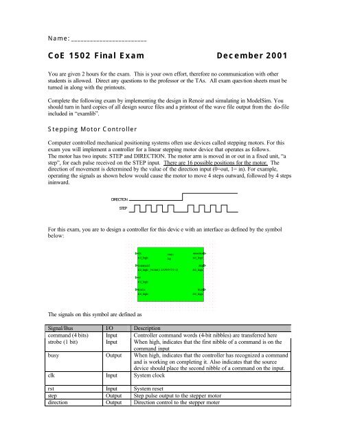
For this <strong>exam</strong>, you are to design a controller for this devic e with an interface as defined by the symbol<br />
below:<br />
The signals on this symbol are defined as<br />
Signal/Bus I/O Description<br />
command (4 bits) Input Controller command words (4-bit nibbles) are transferred here<br />
strobe (1 bit) Input When high, indicates that the first nibble of a command is on the<br />
command input<br />
busy Output When high, indicates that the controller has recognized a command<br />
and is working on completing it. Also indicates that the source<br />
device should place the second nibble of a command on the input.<br />
clk Input System clock<br />
rst Input System reset<br />
step Output Step pulse output to the stepper motor<br />
direction Output Direction control to the stepper moter
There are three commands defined for the controller as defined in the table below<br />
Command Nibble 1 Nibble 2 Effect<br />
STEP IN 1000 <br />
(4-bits)<br />
Causes the controller to step the motor in “step<br />
amount” number of steps<br />
STEP OUT 0100 <br />
(4-bits)<br />
Causes the controller to step the motor out “step<br />
amount” number of steps<br />
HOME 0010 None Causes the controller to return the motor to the zero<br />
position.<br />
The STEP IN and STEP out command are two nibbles (4 bits) long and require two transfers on the<br />
command inputs. The HOME command requires only a single nibble. In the case of two nibble<br />
commands, the source device will place the second nibble on the bus after the controller makes the<br />
BUSY/ACK signal high.<br />
The following timing is an <strong>exam</strong>ple STEP OUT 2 command.<br />
clock<br />
command (4 bits)<br />
strobe<br />
busy/ack<br />
direction<br />
pulse<br />
xxxx 0100 0010 xxxx<br />
Figure 4: ModelSim results for correct solution
Implementation Notes<br />
Your top level block diagram MUST BE NAMED ‘top’. Create a new library called ‘<strong>exam</strong>’, mapped in<br />
your HOME DIRECTORY on the H drive. You will do your design in this library.<br />
In order to implement this system, you will need access to the up/down counter component and a<br />
testbench that we have designed for you. It is in the <strong>exam</strong>lib library (at I:\1502\<strong>exam</strong>lib) and you’ll have<br />
to set this up.<br />
Submission<br />
When you’re done with your project, open the top_tb component in the <strong>exam</strong>lib library and simulate it.<br />
When Modelsim opens, simply run the “<strong>exam</strong>.do” file which is located in I:\1502\<strong>exam</strong>lib directory. This<br />
is the testbench for your design.<br />
Components We Provide<br />
The counter has the following symbol:<br />
Figure 5: Up/down counter symbol<br />
Signal/Bus I/O Description<br />
en, clk, rst input Standard register en, clk, rst<br />
load input Assert to load counter from D (counter must be enabled)<br />
D input Value to be loaded<br />
updown input Deassert to count down, assert to count up (load must be low and<br />
counter must be enabled)<br />
Q output Current value of counter<br />
zero output Asserted when counter value is 0<br />
Note: This counter is rising edge activated. If you’re unsure about the operation of the counter, you can<br />
view its VHDL code.<br />
Hints<br />
• The total design must have exactly one state machine controller (which you will design) and two<br />
of the up/down counters. These three components will be wired up in your block diagram.