OPTISONIC 6300
OPTISONIC 6300
OPTISONIC 6300

You also want an ePaper? Increase the reach of your titles
YUMPU automatically turns print PDFs into web optimized ePapers that Google loves.
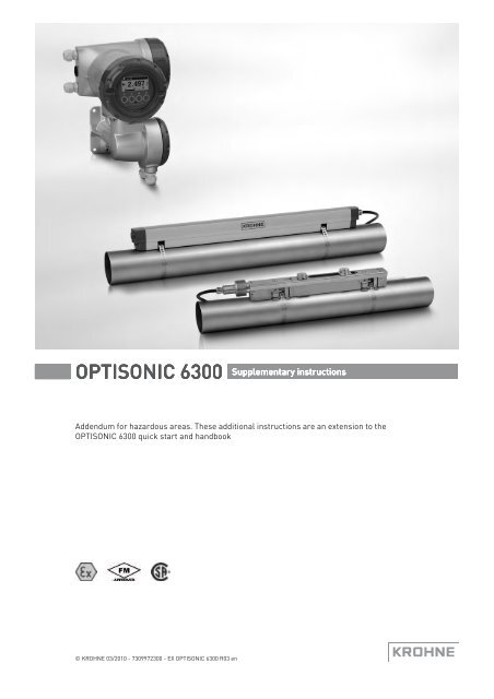
<strong>OPTISONIC</strong> <strong>6300</strong> Supplementary instructions<br />
Addendum for hazardous areas. These additional instructions are an extension to the<br />
<strong>OPTISONIC</strong> <strong>6300</strong> quick start and handbook<br />
© KROHNE 03/2010 - 7309972300 - EX <strong>OPTISONIC</strong> <strong>6300</strong> R03 en
CONTENTS<br />
<strong>OPTISONIC</strong> <strong>6300</strong><br />
1 Introduction 3<br />
1.1 Safety instructions from the manufacturer ..................................................................... 3<br />
1.1.1 Copyright and data protection ................................................................................................ 3<br />
1.1.2 Disclaimer ............................................................................................................................... 3<br />
1.1.3 Product liability and warranty ................................................................................................ 4<br />
1.1.4 Information concerning the documentation........................................................................... 4<br />
1.1.5 Warnings and symbols used................................................................................................... 5<br />
1.1.6 Manufacturer .......................................................................................................................... 5<br />
1.2 Safety instructions for the operator................................................................................. 6<br />
1.3 Approval............................................................................................................................ 7<br />
1.4 <strong>OPTISONIC</strong> 6000 xxxxxx-Ex .............................................................................................. 7<br />
1.5 UFC 300 F(/i)-Ex ............................................................................................................... 8<br />
1.6 Marking labels.................................................................................................................. 9<br />
2 Temperature limits 11<br />
2.1 General ........................................................................................................................... 11<br />
2.2 UFC 300 F(/i)-Ex ............................................................................................................. 12<br />
2.3 <strong>OPTISONIC</strong> 6000 xxxxxx-Ex ............................................................................................ 12<br />
3 Connection of separate systems 13<br />
3.1 General ........................................................................................................................... 13<br />
3.2 Cable marking ................................................................................................................ 13<br />
3.3 Cable parameters...........................................................................................................13<br />
3.4 Equipotential bonding..................................................................................................... 13<br />
3.4.1 Signal converter.................................................................................................................... 13<br />
3.4.2 Flow sensor........................................................................................................................... 13<br />
3.5 Signal cable connections................................................................................................ 14<br />
4 Electrical connections 16<br />
4.1 General ........................................................................................................................... 16<br />
4.2 Non-"Ex i" I/O connections............................................................................................. 18<br />
4.3 "Ex i" I/O connections .....................................................................................................19<br />
5 Maintenance 21<br />
5.1 Maintenance ................................................................................................................... 21<br />
5.2 Before and after opening................................................................................................ 21<br />
5.3 Replacement of mains fuse............................................................................................ 22<br />
5.4 Exchange of electronics unit .......................................................................................... 23<br />
5.4.1 Field version.......................................................................................................................... 24<br />
5.5 Service / repair information ........................................................................................... 26<br />
5.6 Form (for copying) to accompany a returned device ..................................................... 27<br />
5.7 Disposal .......................................................................................................................... 27<br />
2 www.krohne.com 03/2010 - 7309972300 - EX <strong>OPTISONIC</strong> <strong>6300</strong> R03 en
<strong>OPTISONIC</strong> <strong>6300</strong><br />
INTRODUCTION 1<br />
1.1 Safety instructions from the manufacturer<br />
1.1.1 Copyright and data protection<br />
1.1.2 Disclaimer<br />
The contents of this document have been created with great care. Nevertheless, we provide no<br />
guarantee that the contents are correct, complete or up-to-date.<br />
The contents and works in this document are subject to German copyright. Contributions from<br />
third parties are identified as such. Reproduction, processing, dissemination and any type of use<br />
beyond what is permitted under copyright requires written authorisation from the respective<br />
author and/or the manufacturer.<br />
The manufacturer tries always to observe the copyrights of others, and to draw on works created<br />
in-house or works in the public domain.<br />
The collection of personal data (such as names, street addresses or e-mail addresses) in the<br />
manufacturer's documents is always on a voluntary basis whenever possible. Whenever<br />
feasible, it is always possible to make use of the offerings and services without providing any<br />
personal data.<br />
We draw your attention to the fact that data transmission over the Internet (e.g. when<br />
communicating by e-mail) may involve gaps in security. It is not possible to protect such data<br />
completely against access by third parties.<br />
We hereby expressly prohibit the use of the contact data published as part of our duty to publish<br />
an imprint for the purpose of sending us any advertising or informational materials that we have<br />
not expressly requested.<br />
The manufacturer will not be liable for any damage of any kind by using its product, including,<br />
but not limited to direct, indirect, incidental, punitive and consequential damages.<br />
This disclaimer does not apply in case the manufacturer has acted on purpose or with gross<br />
negligence. In the event any applicable law does not allow such limitations on implied warranties<br />
or the exclusion of limitation of certain damages, you may, if such law applies to you, not be<br />
subject to some or all of the above disclaimer, exclusions or limitations.<br />
Any product purchased from the manufacturer is warranted in accordance with the relevant<br />
product documentation and our Terms and Conditions of Sale.<br />
The manufacturer reserves the right to alter the content of its documents, including this<br />
disclaimer in any way, at any time, for any reason, without prior notification, and will not be liable<br />
in any way for possible consequences of such changes.<br />
03/2010 - 7309972300 - EX <strong>OPTISONIC</strong> <strong>6300</strong> R03 en<br />
www.krohne.com<br />
3
1 INTRODUCTION<br />
<strong>OPTISONIC</strong> <strong>6300</strong><br />
1.1.3 Product liability and warranty<br />
Ultrasonic flowmeters are designed solely for measuring the flow rate and the velocity of sound<br />
of process liquids.<br />
Responsibility as to suitability and intended use of these ultrasonic flowmeters rests solely with<br />
the operator. The supplier does not accept any liability resulting from misuse by the operator.<br />
Improper installation and operation of the flowmeters (systems) may lead to loss of warranty. In<br />
addition, the “General conditions of sale“ which forms the basis of the purchase agreement are<br />
applicable.<br />
1.1.4 Information concerning the documentation<br />
To prevent any injury to the user or damage to the device it is essential that you read the<br />
information in this document and observe applicable national standards, safety requirements<br />
and accident prevention regulations.<br />
If this document is not in your native language and if you have any problems understanding the<br />
text, we advise you to contact your local office for assistance. The manufacturer can not accept<br />
responsibility for any damage or injury caused by misunderstanding of the information in this<br />
document.<br />
This document is provided to help you establish operating conditions, which will permit safe and<br />
efficient use of this device. Special considerations and precautions are also described in the<br />
document, which appear in the form of underneath icons.<br />
4<br />
www.krohne.com<br />
03/2010 - 7309972300 - EX <strong>OPTISONIC</strong> <strong>6300</strong> R03 en
<strong>OPTISONIC</strong> <strong>6300</strong><br />
INTRODUCTION 1<br />
1.1.5 Warnings and symbols used<br />
Safety warnings are indicated by the following symbols.<br />
DANGER!<br />
This information refers to the immediate danger when working with electricity.<br />
DANGER!<br />
This warning refers to the immediate danger of burns caused by heat or hot surfaces.<br />
DANGER!<br />
This warning refers to the immediate danger when using this device in a hazardous atmosphere.<br />
DANGER!<br />
These warnings must be observed without fail. Even partial disregard of this warning can lead to<br />
serious health problems and even death. There is also the risk of seriously damaging the device<br />
or parts of the operator's plant.<br />
WARNING!<br />
Disregarding this safety warning, even if only in part, poses the risk of serious health problems.<br />
There is also the risk of damaging the device or parts of the operator's plant.<br />
CAUTION!<br />
Disregarding these instructions can result in damage to the device or to parts of the operator's<br />
plant.<br />
INFORMATION!<br />
These instructions contain important information for the handling of the device.<br />
LEGAL NOTICE!<br />
This note contains information on statutory directives and standards.<br />
• HANDLING<br />
This symbol designates all instructions for actions to be carried out by the operator in the<br />
specified sequence.<br />
i<br />
RESULT<br />
This symbol refers to all important consequences of the previous actions.<br />
1.1.6 Manufacturer<br />
This instrument is developed and manufactured by:<br />
KROHNE Altometer<br />
Kerkeplaat 12<br />
3313 LC Dordrecht<br />
The Netherlands<br />
03/2010 - 7309972300 - EX <strong>OPTISONIC</strong> <strong>6300</strong> R03 en<br />
www.krohne.com<br />
5
1 INTRODUCTION<br />
<strong>OPTISONIC</strong> <strong>6300</strong><br />
For information, maintenance or service please contact your nearest local KROHNE<br />
representative.<br />
1.2 Safety instructions for the operator<br />
WARNING!<br />
• Do not change the device. Unauthorized changes affect the explosion safety of the devices.<br />
• The prescriptions and regulations as well as the electrical data described in the EC type<br />
examination certificate must be obeyed.<br />
• Beside the instructions for electrical installations in non-hazardous locations according to<br />
the applicable national standard (equivalent to HD 384 or IEC 364, e.g. VDE 0100), especially<br />
the regulations in EN 60079-14 "Electrical installations in hazardous locations" or equivalent<br />
national standard (e.g. DIN VDE 0165 Part 1) must be strictly followed.<br />
• Installation, establishment, utilization and maintenance are only allowed to be executed by<br />
personnel with an education in explosion safety!<br />
These additional instructions are an extension to the installation and operating instructions and<br />
only apply tot the Ex-versions of the <strong>OPTISONIC</strong> 6000 and UFC 300 F(/i) ultrasonic flowmeters.<br />
All technical information as described in the Installation and Operating Instructions is<br />
applicable, when not specifically excluded, completed or replaced by the instructions in these<br />
additional instructions.<br />
6<br />
www.krohne.com<br />
03/2010 - 7309972300 - EX <strong>OPTISONIC</strong> <strong>6300</strong> R03 en
<strong>OPTISONIC</strong> <strong>6300</strong><br />
INTRODUCTION 1<br />
1.3 Approval<br />
The ultrasonic flowmeters are manufactured according to the European Directive 94/9 EC (ATEX<br />
100a). These flowmeters are approved for installation and use in hazardous classified locations<br />
of Zone 1 and 2 by the PTB and are in accordance with the European Standards of the EN 60079<br />
series. They have approval number:<br />
<strong>OPTISONIC</strong> 6000 xxxxxx-Ex sensor: PTB 06 ATEX 2045 X<br />
UFC 300 F(/i)-Ex converter: PTB 06 ATEX 2046 X<br />
The FM approval original project ID is 3029326.<br />
The CSA approval certificate is 1956404 (LR 105802).<br />
1.4 <strong>OPTISONIC</strong> 6000 xxxxxx-Ex<br />
The <strong>OPTISONIC</strong> 6000 xxxxxx-Ex is a clamp-on ultrasonic flow sensor and has intrinsically safe<br />
transducer circuits. It is available in three sizes (xxxxxx = small, medium or large), designed for<br />
the size of the pipeline on which the flow sensor is installed.<br />
It is marked with the explosion safety code:<br />
II 2 G Ex ia IIC T6...T4<br />
II 2 G Ex ia IIC T6...T2 (XT versions)<br />
The intrinsically safe transducer connections of the <strong>OPTISONIC</strong> 6000 xxxxxx-Ex are connected to<br />
an associated device and have the following maximum values:<br />
U i = 8,5 V I i = 250 mA P i ≤ 0,625 W C i ≤ 4,5 nF L i ≤ 400 µH<br />
03/2010 - 7309972300 - EX <strong>OPTISONIC</strong> <strong>6300</strong> R03 en<br />
www.krohne.com<br />
7
1 INTRODUCTION<br />
<strong>OPTISONIC</strong> <strong>6300</strong><br />
1.5 UFC 300 F(/i)-Ex<br />
The UFC 300 F(/i)-Ex is the separate version of the ultrasonic signal converter and has<br />
intrinsically safe connections to the ultrasonic flow sensor in separate version. The ultrasonic<br />
signal converter is either provided with increased safety or intrinsically safe in-/outputs that are<br />
located in the terminal compartment, which can either be configured as “Ex d” or “Ex e”.<br />
The converter is marked with one of the following codes:<br />
• II 2(1) G Ex de [ia] IIC T6 or II 2 G Ex de [ia] IIC T6 for the terminal compartment of the signal<br />
converter housing in type of protection increased safety "Ex e" in accordance with EN 60079-<br />
7.<br />
• II 2(1) G Ex d [ia] IIC T6 or II 2 G Ex d [ia] IIC T6 for the terminal compartment of the signal<br />
converter housing designed as flameproof enclosure "Ex d" according to EN 60079-1. The<br />
customer must provide "Ex d" approved cable glands in accordance with the European<br />
Directive 94/9 EC (ATEX 100a).<br />
The terminal compartment contains the connecting terminals for the mains supply and in-<br />
/outputs. It has three M20 x 1,5 - 6H cable/conduit entry holes for use with appropiate cable<br />
glands, blind plugs or conduit adapters ("Ex e" or "Ex d" approved).<br />
WARNING!<br />
"Ex d" approved cable glands / blind plugs are not part of the standard delivery package and<br />
must be provided by the customer or explicitly ordered at the manufacturer.<br />
When conduits are used, the terminal compartment must be a flameproof enclosure "Ex d"<br />
according to EN 60079-1. The conduits must be sealed by "Ex d" approved sealing devices, e.g. a<br />
stopping box with setting compound, directly at the conduit entrances.<br />
The intrinsically safe transducer output connections have the following values:<br />
U o = 8,2 V I o = 210 mA P o = 435 mW C o = 1,3 μF or 0,8 μF L o = 0,5 mH or 1,2 mH<br />
8<br />
www.krohne.com<br />
03/2010 - 7309972300 - EX <strong>OPTISONIC</strong> <strong>6300</strong> R03 en
<strong>OPTISONIC</strong> <strong>6300</strong><br />
INTRODUCTION 1<br />
1.6 Marking labels<br />
See the marking labels (i.e. data stickers) below of respectively the rail, the cover, the splitter<br />
box (only for large version) and the UFC 300 F(/i)-Ex ultrasonic signal converter.<br />
Figure 1-1: <strong>OPTISONIC</strong> 6000 xxxxxx-Ex rail<br />
Figure 1-2: <strong>OPTISONIC</strong> 6000 xxxxxx / XT-Ex rail<br />
Figure 1-3: <strong>OPTISONIC</strong> 6000 xxxxxx-Ex cover<br />
Figure 1-4: <strong>OPTISONIC</strong> 6000 xxxxxx-Ex splitter box<br />
03/2010 - 7309972300 - EX <strong>OPTISONIC</strong> <strong>6300</strong> R03 en<br />
www.krohne.com<br />
9
1 INTRODUCTION<br />
<strong>OPTISONIC</strong> <strong>6300</strong><br />
Figure 1-5: UFC 300 F(/i)-Ex<br />
The typeplates of the FM approved flowmeters look similar, but they bear the FM logo and the<br />
project ID number.<br />
The typeplates of the CSA approved flowmeters look similar, but they bear the CSA logo and the<br />
certificate number.<br />
INFORMATION!<br />
Stainless steel and XT versions are not availabe with FM or CSA approval.<br />
10<br />
www.krohne.com<br />
03/2010 - 7309972300 - EX <strong>OPTISONIC</strong> <strong>6300</strong> R03 en
<strong>OPTISONIC</strong> <strong>6300</strong><br />
TEMPERATURE LIMITS 2<br />
2.1 General<br />
Due to the influence of the process temperature, ultrasonic flow sensors in separate version<br />
with type designation <strong>OPTISONIC</strong> 6000 xxxxxx-Ex are not allocated to any fixed temperature<br />
class. For the temperature classification table refer to <strong>OPTISONIC</strong> 6000 xxxxxx-Ex on page 12.<br />
The temperature limits apply under the following conditions:<br />
• The instrument is installed and operated in accordance with the installation directions given<br />
in the quickstart and handbook.<br />
• The instrument is not heated up by any additional heat radiation (direct solar radiation, heat<br />
from adjacent plant parts) so causing it to operate above the permissible ambient<br />
temperature range.<br />
• Insulation is not hindering free ventilation of the ultrasonic signal converter housing.<br />
03/2010 - 7309972300 - EX <strong>OPTISONIC</strong> <strong>6300</strong> R03 en<br />
www.krohne.com<br />
11
2 TEMPERATURE LIMITS<br />
<strong>OPTISONIC</strong> <strong>6300</strong><br />
2.2 UFC 300 F(/i)-Ex<br />
The UFC 300 F(/i)-Ex ultrasonic signal converter in separate version is not influenced by the<br />
temperature of the process medium, because it is installed on a distance of the pipe-line and<br />
thus not physically connected to the pipe-line. The UFC 300 F(/i)-Ex signal converter has a<br />
temperature classification of T6 (85°C). The permissible ambient temperature is dependent on<br />
the material that the electronics housing is made of, namely:<br />
• die-casted aluminum: -40...+60ºC<br />
• die-casted stainless steel: -40...+55ºC<br />
2.3 <strong>OPTISONIC</strong> 6000 xxxxxx-Ex<br />
The <strong>OPTISONIC</strong> 6000 xxxxxx-Ex clamp-on ultrasonic flow sensor has the following maximum<br />
process temperatures at the maximum ambient temperature T a of 70°C.<br />
Temperature class Maximum process temperature [ºC] [<br />
at T a = 70ºC<br />
T6 80<br />
T5 95<br />
T4 120 1<br />
T3 195 2<br />
T2 200 2<br />
1 XT version: 130°C<br />
2 XT versions only<br />
12<br />
www.krohne.com<br />
03/2010 - 7309972300 - EX <strong>OPTISONIC</strong> <strong>6300</strong> R03 en
<strong>OPTISONIC</strong> <strong>6300</strong><br />
CONNECTION OF SEPARATE SYSTEMS 3<br />
3.1 General<br />
The electrical connection between the ultrasonic flow sensor and the signal converter is<br />
established with MR 02 - RGX 316 triax signal cable. The ends of the coaxial cables are provided<br />
with SMB plugs. The signal cable is provided with the system.<br />
3.2 Cable marking<br />
Please refer to Signal cable connections on page 14 for the connection of the different versions.<br />
3.3 Cable parameters<br />
The maximum permitted total capacitance and inductance for the connecting cable is:<br />
C L = 1,29 μF or 0,79 μF<br />
L L = 0,1 mH or 0,8 mH<br />
The cable supplied with the instrument has the following parameters:<br />
distributed capacitance C C (core/screen) = 94 pF/m<br />
distributed inductance L C (core/screen) = 0,24 μH/m<br />
INFORMATION!<br />
The standard length of the signal cable is 5 m. In case a longer length is required, please contact<br />
your local representative for detailed information.<br />
3.4 Equipotential bonding<br />
3.4.1 Signal converter<br />
The UFC 300 F(/i)-Ex ultrasonic signal converter must always be incorporated within the<br />
equipotential bonding system of the installation in the hazardous classified location. For this<br />
purpose it must be connected to the external U-clamp screw terminal (size M5) on the wallmounting<br />
device.<br />
3.4.2 Flow sensor<br />
The separate bonding conductor must be at least 4 mm 2 (11 AWG) or 2.5 mm 2 (14 AWG) in case it<br />
is mechanically protected, see Clause 413 of HD 384.4.41 or IEC 364-4-41. Make sure that the<br />
core of the bonding wire is properly mounted under the U-clamp of the external M5 terminal and<br />
that the screw is tightly fixed.<br />
The intrinsically safe transducer circuits of the flow sensor are galvanically isolated from earth,<br />
therefore an equipotential bonding conductor between the flow sensor and the signal converter<br />
does not have to be connected.<br />
03/2010 - 7309972300 - EX <strong>OPTISONIC</strong> <strong>6300</strong> R03 en<br />
www.krohne.com<br />
13
3 CONNECTION OF SEPARATE SYSTEMS<br />
<strong>OPTISONIC</strong> <strong>6300</strong><br />
3.5 Signal cable connections<br />
See the pictures below for details.<br />
Figure 3-1: Connecting the signal cable to the rail (small and medium version)<br />
1 Connect the green cable to "DOWN"<br />
2 Connect the blue cable to "UP"<br />
3 Turn the screws clockwise to secure the cap<br />
Figure 3-2: Connections in cable box (large version)<br />
1 Connect the blue cable to the UP rail.<br />
2 Connect the green cable to the DOWN rail.<br />
3 Make connections in cable box.<br />
4 Cable to converter<br />
5 Turn the screws clockwise to secure the caps.<br />
14<br />
www.krohne.com<br />
03/2010 - 7309972300 - EX <strong>OPTISONIC</strong> <strong>6300</strong> R03 en
<strong>OPTISONIC</strong> <strong>6300</strong><br />
CONNECTION OF SEPARATE SYSTEMS 3<br />
Figure 3-3: Construction (field version)<br />
1 Cover, electronics compartment<br />
2 Cover, terminal compartment for power supply and inputs/outputs<br />
3 Cable entry for power<br />
4 Cable entry for inputs/outputs<br />
5 Cable entry for sensor cable<br />
6 Cover, sensor terminal compartment<br />
Figure 3-4: Connect the signal cable in case of stainless steel / XT version.<br />
1 Put in the connector.<br />
2 Turn knob to secure the connector.<br />
03/2010 - 7309972300 - EX <strong>OPTISONIC</strong> <strong>6300</strong> R03 en<br />
www.krohne.com<br />
15
4 ELECTRICAL CONNECTIONS<br />
<strong>OPTISONIC</strong> <strong>6300</strong><br />
4.1 General<br />
The display cover seals the electronics compartment of the converter housing and provides type<br />
of protection “flameproof enclosure”. The terminal compartment is default in type of protection<br />
“increased safety” ("Ex e") and can optionally be performed as flameproof enclosure ("Ex d"). The<br />
threaded joints formed by the covers and housing are a tight fit due to the requirements for type<br />
of protection “flameproof enclosure”. Screw the covers on and off with care and never use<br />
excessive force !<br />
Keep the screw-threads free of dirt and well-greased (e.g. with PTFE grease). The grease will<br />
help to prevent the threads from locking due to corrosion.<br />
To unscrew the covers, first release the interlocking devices (one at each cover). Therefore<br />
unscrew the M4 head screw with internal hexagon socket set using a No. 3 Allen key until the<br />
interlocking device can be turned. After the covers are screwed back onto the housing, make<br />
sure that the interlocking devices are properly refitted.<br />
WARNING!<br />
Allow the electronics to de-energize before opening the electronics compartment of the flow<br />
converter housing. Wait at least 35 minutes for T6 and 10 minutes for T5 before opening.<br />
Figure 4-1: Electrical connections<br />
Terminals<br />
L, N<br />
L+, L-<br />
A, A-, A+<br />
B, B-<br />
C, C-<br />
D, D-<br />
Function, electrical data<br />
Connections for mains supply, always non-Ex i<br />
100...230 V AC, +10%/-15%, 22 VA, 50/60 Hz<br />
12...24 V DC, +30%/-10%, 12W<br />
24 V AC, +10%/-15%, 22 VA, 50/60 Hz<br />
24 V DC, +30%/-25%, 12 W<br />
U m = 253 V<br />
Connections for signal I/Os (PELV circuits), non-“Ex<br />
i” or “Ex i”, are dependent on the specific version of<br />
the UFC 300 converter ordered. Consult the tables<br />
with CG34 numbers for details.<br />
16<br />
www.krohne.com<br />
03/2010 - 7309972300 - EX <strong>OPTISONIC</strong> <strong>6300</strong> R03 en
<strong>OPTISONIC</strong> <strong>6300</strong><br />
ELECTRICAL CONNECTIONS 4<br />
The exact I/O-configuration for circuits A, B, C and D is order-specific and can be determined by<br />
the CG34 number shown on the I/O sticker inside the terminal compartment. Therefore check<br />
the data on the back of the UFC 300 electronics unit. The CG34 number contains 10 characters of<br />
which the last three characters (XYZ) determine the configuration of the I/O circuits:<br />
CG34 * * * X Y Z<br />
Pos 1...4 5 6 7 8 9 10<br />
determine I/O circuits<br />
For schematic overviews of the CG34 numbers, refer to "Ex i" I/O connections on page 19 and<br />
refer to Non-"Ex i" I/O connections on page 18. These overviews do not show all details. The<br />
exact connection diagram of a specific UFC 300 signal converter can be found on the sticker<br />
inside the terminal compartment.<br />
For use in gaseous hazardous areas: The chosen cable glands must have the appropriate type of<br />
protection for the terminal compartment that is increased safety (Ex e) or flameproof enclosure<br />
(Ex d). They MUST be suitable for the conditions of use and correctly installed.<br />
The flowmeter with the terminal compartment in type of protection increased safety “Ex e” is<br />
factory supplied with two “Ex e” approved cable glands and one “Ex e” approved blanking element<br />
(i.e. stopping plug).<br />
WARNING!<br />
The flowmeter with the terminal compartment performed as flameproof enclosure “Ex d” is<br />
supplied with one “Ex d” approved stopping plug and two temporary plugs. The temporary plugs<br />
are only intended for sealing the housing against entry of dust, moisture or else during<br />
transport, handling and storage. These temporary plugs must be replaced by suitable “Ex d”<br />
approved cable glands, stopping plugs or conduit adapters with sealing devices before the<br />
flowmeter is put into operation. Unused openings must be sealed by suitable certified plugs.<br />
The wiring of instruments has to be in accordance with the requirements as specified in the<br />
relevant national or international standard for electrical installations in hazardous areas, e.g.<br />
EN 60079-14. Section 9 (wiring systems) of this standard applies to all types of protection.<br />
Section 10 (additional requirements for type of protection “d” - flameproof enclosures), section<br />
11 (additional requirements for type of protection “e” - increased safety) and section 12<br />
(additional requirements for type of protection “i” - intrinsic safety) apply to respectively “Ex d”,<br />
“Ex e” and “Ex i” performed connection (terminal) compartments.<br />
03/2010 - 7309972300 - EX <strong>OPTISONIC</strong> <strong>6300</strong> R03 en<br />
www.krohne.com<br />
17
4 ELECTRICAL CONNECTIONS<br />
<strong>OPTISONIC</strong> <strong>6300</strong><br />
4.2 Non-"Ex i" I/O connections<br />
The following non-intrinsically safe I/O (inputs/outputs) are available:<br />
I/O PCB<br />
Input/output functions, U n < 32 V DC, I n < 100 mA,<br />
U m = 253 V<br />
Basic I/O<br />
Current Output, active or passive, with HART<br />
Status Output / Control Input<br />
Status Output<br />
Pulse / Status Output<br />
Modular I/O<br />
Current Output, active or passive, with HART<br />
Pulse / Status Output, active or passive, highC or<br />
Namur<br />
Modular carrier with 1 or 2 I/O modules<br />
Each module: 1 out of following 3 in-/output<br />
functions:<br />
Current Output, active or passive<br />
Pulse / Status Output, active or passive, highC or<br />
Namur<br />
Control Input, active or passive, highC or Namur<br />
The options separated by “/” are software selectable (can be changed by the user)<br />
The options separated by “or” are hardware versions (must be ordered as such)<br />
All outputs are passive unless otherwise indicated<br />
HighC means High Current input/output, Namur means that the in-/outputs are according to the NAMUR<br />
NE43 standard<br />
Overview of the possible combinations, defined by characters XYZ of the CG34 number<br />
Characters XYZ<br />
Name of I/O<br />
Terminals<br />
Terminals<br />
Terminals<br />
circuits<br />
A, A-, A+<br />
B, B-<br />
C, C-<br />
Terminals<br />
D, D-<br />
SO/CI SO PO/SO<br />
100 Basic I/O CO<br />
CO(a) over A+<br />
488 to 4LL Modular I/O Many combinations possible<br />
588 to 5LL<br />
688 to 6LL<br />
788 to 7LL<br />
888 to 8LL<br />
A88 to ALL<br />
B88 to BLL<br />
C88 to CLL<br />
or<br />
Modular<br />
Carrier with 1<br />
or 2 I/O<br />
modules<br />
Used abbreviations for in-/output functions: CO = Current Output, PO = Pulse Output, SO = Status Output,<br />
CI = Control Input, PA = Profibus PA, FF = Foundation Fieldbus, DP = Profibus DP, RS485 = RS485 Modbus,<br />
n.c. = not connected.<br />
All in-/outputs are passive unless otherwise noted as active with extension (a).<br />
18<br />
www.krohne.com<br />
03/2010 - 7309972300 - EX <strong>OPTISONIC</strong> <strong>6300</strong> R03 en
<strong>OPTISONIC</strong> <strong>6300</strong><br />
ELECTRICAL CONNECTIONS 4<br />
4.3 "Ex i" I/O connections<br />
The following intrinsically safe I/O connections are available:<br />
I/O PCB<br />
Exi-IO<br />
Exi-Option<br />
I/O functions<br />
Current Output + HART<br />
communication<br />
Pulse / Status Output<br />
Current Output, active + HART<br />
communication<br />
Current Output<br />
Pulse / Status Output / Control<br />
Input<br />
Current Output, active<br />
Ex ia IIC<br />
U i = 30 V, I i = 100 mA, P i = 1,0 W<br />
C i = 10 nF, L i = negligibly low<br />
Ex ia IIC<br />
U o = 21 V, I o = 90 mA, P o = 0,5 W<br />
Lineair characteristics<br />
C o = 90 nF, L o = 2,0 mH<br />
C o = 110 nF, L o = 0,5 mH<br />
Ex ia IIC<br />
U i = 30 V, I i = 100 mA, P i = 1,0 W<br />
C i = 10 nF, L i = negligibly low<br />
Ex ia IIC<br />
U o = 21 V, I o = 90 mA, P o = 0,5 W<br />
Lineair characteristics<br />
C o = 90 nF, L o = 2,0 mH<br />
C o = 110 nF, L o = 0,5 mH<br />
The I/O circuits titled “Exi-IO” and “Exi-Option” are always provided with type of protection<br />
Intrinsic Safety (Ex ia).<br />
Up to a maximum of 4 intrinsically safe (Ex ia) in-/outputs are possible. All intrinsically safe<br />
circuits are galvanically isolated with respect to earth and each other. To avoid summation of<br />
voltages and current, the wiring of these “Ex ia”-circuits must be sufficiently separated, e.g. in<br />
accordance with the requirements of standard EN 60079-14, clause 12.2.<br />
The “Ex ia” in-/outputs may only be connected to other “Ex ia” or “Ex ib” approved devices (e.g.<br />
intrinsically safe isolation amplifiers), even if such devices are installed in a non-hazardous<br />
location !<br />
Connection to non-“Ex i” devices cancels the “Ex ia” properties of the flowmeter.<br />
Terminals L and N (or L+ and L-) for connection of the mains supply are not available with type of<br />
protection “intrinsic safety”. To achieve the necessary separation distances according to EN<br />
60079-11 between the non-”Ex i” and “Ex i” circuits, the mains terminals are provided with a<br />
semi-circular protection cover with a “snap-in” lock. This cover MUST be closed before<br />
establishing the power supply to the converter.<br />
03/2010 - 7309972300 - EX <strong>OPTISONIC</strong> <strong>6300</strong> R03 en<br />
www.krohne.com<br />
19
4 ELECTRICAL CONNECTIONS<br />
<strong>OPTISONIC</strong> <strong>6300</strong><br />
INFORMATION!<br />
For converters with an “Ex e” terminal compartment, the compartment can be opened in an<br />
energized state for short periods of time, to access the intrinsically safe terminals for possible<br />
checks. However, the semi-circular insulation cover over the non-intrinsically safe mains supply<br />
terminals L and N (or L+ and L-) MUST be kept closed.<br />
Overview of possible "Ex ia" in-/outputs, defined by characters XYZ of the CG 34 numbers<br />
Characters XYZ<br />
Name of I/O<br />
circuits<br />
Terminals<br />
A, A-, A+<br />
Terminals<br />
B, B-<br />
Terminals<br />
C, C-<br />
Terminals<br />
D, D-<br />
200 Exi-IO n.c. n.c. CO(a) PO/SO<br />
300 n.c. n.c. CO PO/SO<br />
210 Exi-IO with Exi- CO(a) PO/SO/CI CO(a) PO/SO<br />
220<br />
Option<br />
CO PO/SO/CI CO(a) PO/SO<br />
310 CO(a) PO/SO/CI CO PO/SO<br />
320 CO PO/SO/CI CO PO/SO<br />
Used abbreviations for in-/output functions: CO = Current Output, PO = Pulse Output, SO = Status Output,<br />
CI = Control Input, n.c. = not connected<br />
All in-outputs are passive unless otherwise noted as active with extension (a).<br />
20<br />
www.krohne.com<br />
03/2010 - 7309972300 - EX <strong>OPTISONIC</strong> <strong>6300</strong> R03 en
<strong>OPTISONIC</strong> <strong>6300</strong><br />
MAINTENANCE 5<br />
5.1 Maintenance<br />
The flowmeters are maintenance free with respect to the flowmetering properties. Within the<br />
scope of periodic inspections required for electrical equipment installed in hazardous areas it is<br />
recommended to check the flameproof converter housing and covers for signs of damage or<br />
corrosion.<br />
5.2 Before and after opening<br />
WARNING!<br />
the following instructions must always be carefully followed, if the housing of the signal<br />
converter has to be opened respectively closed again.<br />
Before opening:<br />
• Make absolutely sure that there is no explosion hazard!<br />
• Gas-free certificate!<br />
• Make sure that all connecting cables are safely isolated from all external sources!<br />
• Allow the electronics to de-energize before opening the electronics compartment of the<br />
converter housing. Wait at least 35 minutes for T6 and 10 minutes for T5 before opening.<br />
When the instructions above are strictly followed, the display cover (includes glass window) of<br />
the electronics compartment may be removed. First unscrew the head screw with internal<br />
hexagon socket set (size M4) of the interlocking device by a No. 3 Allen key, until the cover can<br />
rotate freely.<br />
After opening:<br />
• Before the cover is screwed back onto the housing, the screw-thread must be clean and wellgreased<br />
with an acid and resin-free grease, e.g. PTFE grease.<br />
• Screw the cover as tight as possible onto the housing by hand, until it cannot be opened by<br />
hand anymore. Fixate the screw of the interlocking device tight with the No. 3 Allen key.<br />
03/2010 - 7309972300 - EX <strong>OPTISONIC</strong> <strong>6300</strong> R03 en<br />
www.krohne.com<br />
21
5 MAINTENANCE<br />
<strong>OPTISONIC</strong> <strong>6300</strong><br />
5.3 Replacement of mains fuse<br />
WARNING!<br />
Before commencing the work, refer to Before and after opening on page 21, then continue as<br />
follows:<br />
• Pull the display unit of the mounting frame and turn display unit carefully aside.<br />
• Unscrew the two screws size M4 that hold the mounting frame with the electronics unit.<br />
• Carefully pull the mounting frame with electronics unit out of the housing, until the small<br />
printed circuit board with the six soldered coaxial cables can be pulled off of the sensor driver<br />
PC-board. Now carefully remove the unit from the housing, while keeping the small printed<br />
circuit board with coaxial cables down, close to the housing wall.<br />
• The mains fuse is located in a fuse holder at the back-end of the electronics unit on the top<br />
printed circuit board (power supply PCB). The specifications must be as follows:<br />
Fuse type: 5 x 20 mm (H) according to IEC 60127-2/V<br />
Power supply<br />
Electrical data<br />
12...24 V DC 250 V / 2 A<br />
24 V AC/DC 250 V / 2 A<br />
100...230 V AC 250 V / 0,8 A<br />
WARNING!<br />
Before reassembling the unit, refer to Before and after opening on page 21, then:<br />
• Reassemble the unit in reverse order.<br />
22<br />
www.krohne.com<br />
03/2010 - 7309972300 - EX <strong>OPTISONIC</strong> <strong>6300</strong> R03 en
<strong>OPTISONIC</strong> <strong>6300</strong><br />
MAINTENANCE 5<br />
5.4 Exchange of electronics unit<br />
Before opening the converter housing:<br />
DANGER!<br />
All work on the electrical connections may only be carried out with the power disconnected. Take<br />
note of the voltage data on the nameplate!<br />
WARNING!<br />
Observe without fail the local occupational health and safety regulations. Any work done on the<br />
electrical components of the measuring device may only be carried out by properly trained<br />
specialists.<br />
INFORMATION!<br />
Make notes of important specific data, before exchanging the electronics.<br />
Menu settings are stored on the circuit board (or backplane), that is fixed to the housing. After<br />
exchange of electronics unit and power-up, the following start up screen appears:<br />
Load all data?<br />
• Select yes<br />
i - if in the screen appears “load sensor data”, the electronics units were not fully<br />
compatible. You can proceed by selecting yes. Note that all settings need to be checked and<br />
changed. Only the sensor calibration data are loaded.<br />
- if in the screen appears “load no data”, all data have been lost. Contact your local<br />
representative.<br />
03/2010 - 7309972300 - EX <strong>OPTISONIC</strong> <strong>6300</strong> R03 en<br />
www.krohne.com<br />
23
5 MAINTENANCE<br />
<strong>OPTISONIC</strong> <strong>6300</strong><br />
5.4.1 Field version<br />
DANGER!<br />
All work on the electrical connections may only be carried out with the power disconnected. Take<br />
note of the voltage data on the nameplate!<br />
Figure 5-1: Unscrew the cover and remove the display<br />
Figure 5-2: Pull off printed circuit board<br />
Perform the following procedures:<br />
• Unscrew the display cover of the electronics compartment by hand, by turning it counter<br />
clockwise 1.<br />
• Remove the display by using two screwdrivers 2.<br />
• Unscrew the two M4 screws 3 at the electronics unit 4.<br />
• Pull the two metal pullers 5 at the left and right of the display, using a screwdriver or similar<br />
tool and partially pull out the electronics unit.<br />
CAUTION!<br />
Please pay attention that the same amount of force is applied on both pullers, otherwise the<br />
connector at the backside can be damaged.<br />
24<br />
www.krohne.com<br />
03/2010 - 7309972300 - EX <strong>OPTISONIC</strong> <strong>6300</strong> R03 en
<strong>OPTISONIC</strong> <strong>6300</strong><br />
MAINTENANCE 5<br />
Figure 5-3: Small printed circuit board and electronics unit<br />
DANGER!<br />
Electrostatic discharge (ESD) can damage electronic parts. Make sure to discharge yourself by<br />
wearing a wrist strap. If no wrist strap is available, ground yourself by touching a metal surface<br />
that is grounded.<br />
• Remove the printed circuit board 6 from the electronics unit 4.<br />
• Check compatibility between the removed and new electronics unit 4, by checking the power<br />
voltage.<br />
• Slide the new electronics unit 4 partially back into the housing.<br />
• Mount the small printed circuit board back onto the electronics unit 4.<br />
• Push the metal pullers 5 back to their original position.<br />
Don't use excessive force, otherwise the connector at the backside can be damaged!<br />
• Screw the electronics unit back to the housing.<br />
• Re-install the display and make sure not to kink the display's flat ribbon cable.<br />
• Replace cover and tighten by hand.<br />
• Connect power.<br />
03/2010 - 7309972300 - EX <strong>OPTISONIC</strong> <strong>6300</strong> R03 en<br />
www.krohne.com<br />
25
5 MAINTENANCE<br />
<strong>OPTISONIC</strong> <strong>6300</strong><br />
5.5 Service / repair information<br />
This device has been carefully manufactured and tested. If installed and operated in accordance<br />
with these operating instructions, it will rarely present any problems.<br />
CAUTION!<br />
Should you nevertheless need to return a device for inspection or repair, please pay strict<br />
attention to the following points:<br />
• Due to statutory regulations on environmental protection and safeguarding the health and<br />
safety of our personnel, the manufacturer may only handle, test and repair returned devices<br />
that have been in contact with products without risk to personnel and environment.<br />
• This means that the manufacturer can only service this device if it is accompanied by the<br />
following certificate (see next section) confirming that the device is safe to handle.<br />
CAUTION!<br />
If the device has been operated with toxic, caustic, flammable or water-endangering products,<br />
you are kindly requested:<br />
• to check and ensure, if necessary by rinsing or neutralizing, that all cavities are free from<br />
such dangerous substances,<br />
• to enclose a certificate with the device confirming that is safe to handle and stating the<br />
product used.<br />
26<br />
www.krohne.com<br />
03/2010 - 7309972300 - EX <strong>OPTISONIC</strong> <strong>6300</strong> R03 en
<strong>OPTISONIC</strong> <strong>6300</strong><br />
MAINTENANCE 5<br />
5.6 Form (for copying) to accompany a returned device<br />
Company:<br />
Address:<br />
Department:<br />
Name:<br />
Tel. no.:<br />
Fax no.:<br />
Manufacturer's order no. or serial no.:<br />
The device has been operated with the following medium:<br />
This medium is:<br />
water-hazardous<br />
toxic<br />
caustic<br />
flammable<br />
We checked that all cavities in the device are free from such<br />
substances.<br />
We have flushed out and neutralized all cavities in the<br />
device.<br />
We hereby confirm that there is no risk to persons or the environment through any residual media<br />
contained in the device when it is returned.<br />
Date:<br />
Signature:<br />
Stamp:<br />
5.7 Disposal<br />
CAUTION!<br />
Disposal must be carried out in accordance with legislation applicable in your country.<br />
03/2010 - 7309972300 - EX <strong>OPTISONIC</strong> <strong>6300</strong> R03 en<br />
www.krohne.com<br />
27
KROHNE product overview<br />
© KROHNE 03/2010 - 7309972300 - EX <strong>OPTISONIC</strong> <strong>6300</strong> R03 en - Subject to change without notice.<br />
• Electromagnetic flowmeters<br />
• Variable area flowmeters<br />
• Ultrasonic flowmeters<br />
• Mass flowmeters<br />
• Vortex flowmeters<br />
• Flow controllers<br />
• Level meters<br />
• Temperature meters<br />
• Pressure meters<br />
• Analysis products<br />
• Measuring systems for the oil and gas industry<br />
• Measuring systems for sea-going tankers<br />
Head Office KROHNE Messtechnik GmbH<br />
Ludwig-Krohne-Str. 5<br />
D-47058 Duisburg (Germany)<br />
Tel.:+49 (0)203 301 0<br />
Fax:+49 (0)203 301 10389<br />
info@krohne.de<br />
The current list of all KROHNE contacts and addresses can be found at:<br />
www.krohne.com