Installation and Operating Instructions R.O.C.O.F ... - Crompton
Installation and Operating Instructions R.O.C.O.F ... - Crompton
Installation and Operating Instructions R.O.C.O.F ... - Crompton

You also want an ePaper? Increase the reach of your titles
YUMPU automatically turns print PDFs into web optimized ePapers that Google loves.
Section 2<br />
Technical<br />
Theoretical Considerations<br />
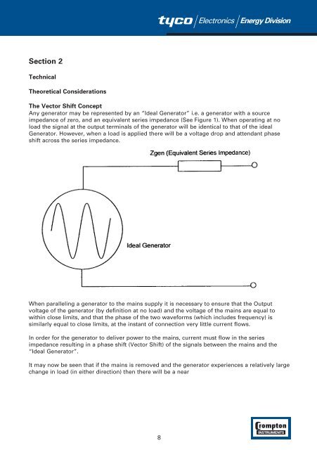
The Vector Shift Concept<br />
Any generator may be represented by an “Ideal Generator” i.e. a generator with a source<br />
impedance of zero, <strong>and</strong> an equivalent series impedance (See Figure 1). When operating at no<br />
load the signal at the output terminals of the generator will be identical to that of the ideal<br />
Generator. However, when a load is applied there will be a voltage drop <strong>and</strong> attendant phase<br />
shift across the series impedance.<br />
When paralleling a generator to the mains supply it is necessary to ensure that the Output<br />
voltage of the generator (by definition at no load) <strong>and</strong> the voltage of the mains are equal to<br />
within close limits, <strong>and</strong> that the phase of the two waveforms (which includes frequency) is<br />
similarly equal to close limits, at the instant of connection very little current flows.<br />
In order for the generator to deliver power to the mains, current must flow in the series<br />
impedance resulting in a phase shift (Vector Shift) of the signals between the mains <strong>and</strong> the<br />
“Ideal Generator”.<br />
It may now be seen that if the mains is removed <strong>and</strong> the generator experiences a relatively large<br />
change in load (in either direction) then there will be a near<br />
8