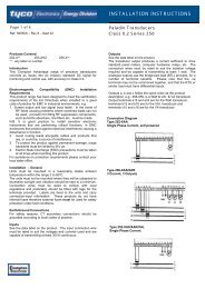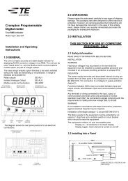
Installation and Operating Instructions R.O.C.O.F ... - Crompton
Installation and Operating Instructions R.O.C.O.F ... - Crompton
Installation and Operating Instructions R.O.C.O.F ... - Crompton

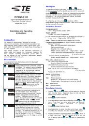
Create successful ePaper yourself
Turn your PDF publications into a flip-book with our unique Google optimized e-Paper software.
Section 3<br />
Interfacing<br />
<strong>Installation</strong><br />
For reliable operation the unit’s signal connections should be connected as close to the<br />
generator as is practical. The unit uses the vector shift produced by the generators characteristic<br />
impedance when the generator load changes. Any additional impedance introduced by bus bars<br />
etc., which could introduce vector shifts during normal operation (not mains failure) should be<br />
avoided in the connection to the unit as it may be necessary to “de-sensitise” the vector shift<br />
trip point to avoids nuisance trips.<br />
EMC <strong>Instructions</strong><br />
While all practical measures have been taken to avoid the susceptibility to Radio Frequency<br />
Interference (R.F.I) when used in particularly noisy environments, consideration must be given<br />
to providing a screened environment for the product. The unit has been designed to comply<br />
with Industrial Immunity Specification EN 50082-2, to withst<strong>and</strong> voltage surges of 4kV peak <strong>and</strong><br />
to comply with the limits of emissions detail din EN50081-2.<br />
It is recommended that external Surge Suppression Barriers are introduced into the Auxiliary<br />
<strong>and</strong> Signal connections in situations where 4kV surges are anticipated, as a guide the surge<br />
protection barrier should limit the output voltage to 2kV.<br />
The “Inhibit” <strong>and</strong> Reset” connections are not electrically isolated from one another <strong>and</strong> should<br />
be connected using cable incorporating a common screen to prevent differential signals entering<br />
the unit along these lines. The screened cable used for the Inhibit <strong>and</strong> Reset connections should<br />
be segregated from sources of electrical noise.<br />
Low Voltage Directive<br />
This product complies with BS EN 61010-1: 1993 AMD 8961:1995 for:<br />
Permanently connected use<br />
Normal Condition<br />
Basic Insulation<br />
<strong>Installation</strong> Category III<br />
Pollution Degree 2<br />
Warning: All terminals are for use only with equipment which has no live parts which are<br />
“Accessible” <strong>and</strong> that the insulation for external circuits is suitable for “Single Fault Conditions”.<br />
18