DALI manual - Tridonic
DALI manual - Tridonic
DALI manual - Tridonic

You also want an ePaper? Increase the reach of your titles
YUMPU automatically turns print PDFs into web optimized ePapers that Google loves.
luxCONTROL<br />
<strong>DALI</strong> <strong>manual</strong>
c<br />
.<br />
<strong>Tridonic</strong> GmbH & Co KG<br />
Färbergasse 15<br />
6851 Dornbirn<br />
Austria<br />
Version 3.0<br />
www.tridonic.com<br />
Subject to change without prior notice. All information is subject to change<br />
2 / 93
.<br />
c<br />
Table of contents<br />
Table of contents<br />
Introduction: <strong>DALI</strong> standard . . . . . . . . . . . . . . . . . . . . . . . . . . . . . . . . . . . . . . . . . . . . . . . . . . . . . . . . . . . . . . 4<br />
History . . . . . . . . . . . . . . . . . . . . . . . . . . . . . . . . . . . . . . . . . . . . . . . . . . . . . . . . . . . . . . . . . . . . . . . . . . . . . . . . . . . . 4<br />
Features of <strong>DALI</strong> . . . . . . . . . . . . . . . . . . . . . . . . . . . . . . . . . . . . . . . . . . . . . . . . . . . . . . . . . . . . . . . . . . . . . . . . . . . . 5<br />
Technical features of a <strong>DALI</strong> circuit . . . . . . . . . . . . . . . . . . . . . . . . . . . . . . . . . . . . . . . . . . . . . . . . . . . . . . . . . . . . . . 5<br />
Scene and group concept . . . . . . . . . . . . . . . . . . . . . . . . . . . . . . . . . . . . . . . . . . . . . . . . . . . . . . . . . . . . . . . . . . . . . 6<br />
Positioning of <strong>DALI</strong> . . . . . . . . . . . . . . . . . . . . . . . . . . . . . . . . . . . . . . . . . . . . . . . . . . . . . . . . . . . . . . . . . . . . . . . . . . 7<br />
Overview of <strong>DALI</strong> controllers and <strong>DALI</strong> control gear . . . . . . . . . . . . . . . . . . . . . . . . . . . . . . . . . . . . . . . . . . . 8<br />
<strong>DALI</strong> controllers of comfortDIM product series . . . . . . . . . . . . . . . . . . . . . . . . . . . . . . . . . . . . . . . . . . . . . . . . . . . . . 8<br />
<strong>DALI</strong> interface modules . . . . . . . . . . . . . . . . . . . . . . . . . . . . . . . . . . . . . . . . . . . . . . . . . . . . . . . . . . . . . . . . . . . . . . 14<br />
<strong>DALI</strong> devices . . . . . . . . . . . . . . . . . . . . . . . . . . . . . . . . . . . . . . . . . . . . . . . . . . . . . . . . . . . . . . . . . . . . . . . . . . . . . . 15<br />
Miscellaneous . . . . . . . . . . . . . . . . . . . . . . . . . . . . . . . . . . . . . . . . . . . . . . . . . . . . . . . . . . . . . . . . . . . . . . . . . . . . . 20<br />
comfortDIM product series in detail . . . . . . . . . . . . . . . . . . . . . . . . . . . . . . . . . . . . . . . . . . . . . . . . . . . . . . . 21<br />
<strong>DALI</strong> power supply . . . . . . . . . . . . . . . . . . . . . . . . . . . . . . . . . . . . . . . . . . . . . . . . . . . . . . . . . . . . . . . . . . . . . . . . . 21<br />
<strong>DALI</strong> group controllers: <strong>DALI</strong> GC & GC-A . . . . . . . . . . . . . . . . . . . . . . . . . . . . . . . . . . . . . . . . . . . . . . . . . . . . . . . . 23<br />
<strong>DALI</strong> scene controllers: <strong>DALI</strong>-SC & SC-A . . . . . . . . . . . . . . . . . . . . . . . . . . . . . . . . . . . . . . . . . . . . . . . . . . . . . . . . 31<br />
<strong>DALI</strong> multi controller: <strong>DALI</strong> MC . . . . . . . . . . . . . . . . . . . . . . . . . . . . . . . . . . . . . . . . . . . . . . . . . . . . . . . . . . . . . . . . 35<br />
Configuration by masterCONFIGURATOR . . . . . . . . . . . . . . . . . . . . . . . . . . . . . . . . . . . . . . . . . . . . . . . . . . . . . . . 36<br />
<strong>DALI</strong> TOUCHPANEL 02 . . . . . . . . . . . . . . . . . . . . . . . . . . . . . . . . . . . . . . . . . . . . . . . . . . . . . . . . . . . . . . . . . . . . . 42<br />
<strong>DALI</strong> x/e-touchPANEL 02 . . . . . . . . . . . . . . . . . . . . . . . . . . . . . . . . . . . . . . . . . . . . . . . . . . . . . . . . . . . . . . . . . . . . 46<br />
<strong>DALI</strong> sequencer module: <strong>DALI</strong> SQM . . . . . . . . . . . . . . . . . . . . . . . . . . . . . . . . . . . . . . . . . . . . . . . . . . . . . . . . . . . . 51<br />
<strong>DALI</strong> MSensor 02 . . . . . . . . . . . . . . . . . . . . . . . . . . . . . . . . . . . . . . . . . . . . . . . . . . . . . . . . . . . . . . . . . . . . . . . . . . 53<br />
<strong>DALI</strong> USB . . . . . . . . . . . . . . . . . . . . . . . . . . . . . . . . . . . . . . . . . . . . . . . . . . . . . . . . . . . . . . . . . . . . . . . . . . . . . . . . 57<br />
Designing a <strong>DALI</strong> application . . . . . . . . . . . . . . . . . . . . . . . . . . . . . . . . . . . . . . . . . . . . . . . . . . . . . . . . . . . . 58<br />
Conventional wiring or <strong>DALI</strong> . . . . . . . . . . . . . . . . . . . . . . . . . . . . . . . . . . . . . . . . . . . . . . . . . . . . . . . . . . . . . . . . . . 58<br />
Design considerations . . . . . . . . . . . . . . . . . . . . . . . . . . . . . . . . . . . . . . . . . . . . . . . . . . . . . . . . . . . . . . . . . . . . . . . 58<br />
Sample applications . . . . . . . . . . . . . . . . . . . . . . . . . . . . . . . . . . . . . . . . . . . . . . . . . . . . . . . . . . . . . . . . . . . . . . . . 63<br />
Start-up . . . . . . . . . . . . . . . . . . . . . . . . . . . . . . . . . . . . . . . . . . . . . . . . . . . . . . . . . . . . . . . . . . . . . . . . . . . . 70<br />
Before you get started . . . . . . . . . . . . . . . . . . . . . . . . . . . . . . . . . . . . . . . . . . . . . . . . . . . . . . . . . . . . . . . . . . . . . . . 70<br />
Sample set-up for a conference room . . . . . . . . . . . . . . . . . . . . . . . . . . . . . . . . . . . . . . . . . . . . . . . . . . . . . . . . . . . 71<br />
Maintenance and troubleshooting . . . . . . . . . . . . . . . . . . . . . . . . . . . . . . . . . . . . . . . . . . . . . . . . . . . . . . . . 82<br />
Failure of a <strong>DALI</strong> ballast . . . . . . . . . . . . . . . . . . . . . . . . . . . . . . . . . . . . . . . . . . . . . . . . . . . . . . . . . . . . . . . . . . . . . 82<br />
Exceeding the maximum cable length or short-circuits in the <strong>DALI</strong> circuit . . . . . . . . . . . . . . . . . . . . . . . . . . . . . . . 82<br />
Double addressing problem at set-up . . . . . . . . . . . . . . . . . . . . . . . . . . . . . . . . . . . . . . . . . . . . . . . . . . . . . . . . . . . 85<br />
Annex . . . . . . . . . . . . . . . . . . . . . . . . . . . . . . . . . . . . . . . . . . . . . . . . . . . . . . . . . . . . . . . . . . . . . . . . . . . . . . 86<br />
Technical features of a <strong>DALI</strong> circuit . . . . . . . . . . . . . . . . . . . . . . . . . . . . . . . . . . . . . . . . . . . . . . . . . . . . . . . . . . . . . 86<br />
Important <strong>DALI</strong> parameters and <strong>DALI</strong> commands . . . . . . . . . . . . . . . . . . . . . . . . . . . . . . . . . . . . . . . . . . . . . . . . . 87<br />
Current draw of the comfortDIM products in the <strong>DALI</strong> circuit . . . . . . . . . . . . . . . . . . . . . . . . . . . . . . . . . . . . . . . . . 89<br />
<strong>DALI</strong> MSensor 02 broadcast commands and luminaire group commands . . . . . . . . . . . . . . . . . . . . . . . . . . . . . . . 91<br />
Reference list . . . . . . . . . . . . . . . . . . . . . . . . . . . . . . . . . . . . . . . . . . . . . . . . . . . . . . . . . . . . . . . . . . . . . . . . . . . . . . 93<br />
<strong>DALI</strong> Manual | 08-2013 | en<br />
3 / 93
.<br />
c<br />
Introduction: <strong>DALI</strong> standard<br />
Introduction: <strong>DALI</strong> standard<br />
History<br />
The agreement by the lighting industry to adopt a common protocol for digital addressable control of luminaires has<br />
opened up a virtually unlimited number of options for regulating artificial lighting in all applications. This common<br />
protocol is the <strong>DALI</strong> protocol (Digital Addressable Lighting Interface), which has now been internationally standardised<br />
through the IEC.<br />
With the right choice of individual <strong>DALI</strong> components an extremely wide range of requirements can be met, from<br />
operating the lighting system from a simple light switch to lighting management systems for entire office complexes<br />
with thousands of light sources. The new standardisation means that there are no longer any restrictions on the<br />
application of this technology. Any light source, including incandescent lamps, fluorescent lamps, high-intensity<br />
discharge lamps and even LEDs, can be controlled irrespective of whether they are installed in an office, a restaurant<br />
or a street light.<br />
The <strong>DALI</strong> system is based on simplicity of operation. However the demands on electrical system designers and<br />
electricians have increased enormously.<br />
The purpose of this technical <strong>manual</strong> is to describe how the <strong>DALI</strong> system components offered by <strong>Tridonic</strong> operate and<br />
illustrate their functionality by looking at how they can be used in actual practice.<br />
<strong>DALI</strong> stands for “Digital Addressable Lighting Interface” and is an interface protocol for digital communication between<br />
electronic lighting equipment (electronic ballasts, transformers, etc.).<br />
The <strong>DALI</strong> standard was developed by <strong>Tridonic</strong> together with renowned manufacturers of operating and control<br />
equipment. Today, these manufacturers belong to the <strong>DALI</strong> Activity Group which promotes the use of <strong>DALI</strong> and<br />
safeguards its further development.<br />
The <strong>DALI</strong> standard was defined in EN 60929 Annex E until 2009 but is now defined in IEC 62386. This standard also<br />
describes the differences between the various types of device. As a result, long-term compatibility among<br />
manufacturers is guaranteed and the <strong>DALI</strong> standard is ensured a secure future. In addition, compatibility between<br />
products from different manufacturers is supported by a test procedure standardised by the <strong>DALI</strong> Activity Group. All<br />
products that carry the logo of the <strong>DALI</strong> Activity Group have successfully passed this standardised test. <strong>Tridonic</strong><br />
products meet these requirements in full.<br />
<strong>DALI</strong> Manual | 08-2013 | en<br />
4 / 93
.<br />
c<br />
Introduction: <strong>DALI</strong> standard<br />
Features of <strong>DALI</strong><br />
Simplified Installation<br />
No polarity<br />
Stable dimming<br />
function<br />
Distributed<br />
intelligence<br />
Status feedback<br />
Flexibility<br />
Logarithmic dimming<br />
curve<br />
Power lines and control lines can be laid together in the same cable. The wiring may be in<br />
series, in a star arrangement or in mixed form.<br />
There is no need to worry about the polarity (+/-) of the <strong>DALI</strong> control line.<br />
All the luminaires receive the same interference-free digital signal and therefore the same<br />
dimmer value.<br />
<strong>DALI</strong> uses a system of distributed intelligence; multiple controllers (e.g. <strong>DALI</strong> GC)<br />
communicate with intelligent ballasts. Each controller operates as a “master” and controls<br />
communication on the control line. Ballasts react only as “slaves” at the request of the<br />
“master”. Certain parameters are stored directly in the <strong>DALI</strong> unit (e.g. scene values, group<br />
address).<br />
Status reports can be issued by the <strong>DALI</strong> units. Information on faulty lamps for example<br />
can therefore be transferred directly to a higher-ranking system.<br />
Group assignment is set up by means of parameters and not by hard wiring. Lighting<br />
scene values are stored in the <strong>DALI</strong> unit.<br />
The dimming curve is matched to the sensitivity of the eye.<br />
Technical features of a <strong>DALI</strong> circuit<br />
Maximum no. of <strong>DALI</strong><br />
groups<br />
Maximum no. of <strong>DALI</strong><br />
scenes<br />
<strong>DALI</strong> voltage<br />
<strong>DALI</strong> system current<br />
Data transfer rate<br />
Maximum cable length<br />
16<br />
16<br />
9.5 V - 22.5 V, typically 16 V<br />
Max. 250 mA (depending on the installed <strong>DALI</strong> power supply)<br />
1200 baud<br />
The maximum cable length depends on the maximum permitted voltage drop along the<br />
<strong>DALI</strong> cable; this is defined as 2 V max. This corresponds to a maximum cable length of<br />
300 m for a line cross-section of 1.5 mm².<br />
<strong>DALI</strong> Manual | 08-2013 | en<br />
5 / 93
.<br />
c<br />
Introduction: <strong>DALI</strong> standard<br />
½ CAUTION!<br />
When the maximum cable length is calculated the contact resistance must also be taken into account.<br />
A voltage drop of 2 V must not be exceeded!<br />
Scene and group concept<br />
<strong>DALI</strong> scenes<br />
With <strong>DALI</strong> it is possible to store 16 different lighting scenarios in each <strong>DALI</strong> unit so that predefined lighting moods can<br />
be called up for a room (for example the "presentation" scene in a conference room, or a "morning" scene in a<br />
wellness centre). The values of the 16 scenes are stored in the control gear. As soon as the unit receives the<br />
command "Go to scene 1" for example it fades up or down to the value stored in memory. The cross-fade time for the<br />
scene call is also stored in the unit and can be set in steps between 0.7 and 90.5 seconds with the "Fade Time"<br />
parameter.<br />
Figure: Examples of light scenes<br />
"Daytime showroom" scene<br />
"Night-time showroom" scene<br />
<strong>DALI</strong> groups<br />
With <strong>DALI</strong> it is possible to define 16 groups in a <strong>DALI</strong> circuit.<br />
A group is a meaningful collection of luminaires. Group assignment can be edited in <strong>DALI</strong>. It is possible for one <strong>DALI</strong><br />
unit to belong to several groups. This reduces the amount of wiring needed and greatly increases flexibility compared<br />
with non-addressable systems because in these systems the groupings are hard-wired.<br />
<strong>DALI</strong> Manual | 08-2013 | en<br />
6 / 93
.<br />
c<br />
Introduction: <strong>DALI</strong> standard<br />
Positioning of <strong>DALI</strong><br />
<strong>DALI</strong> is not a new system for building control such as LON, KNX and other building management systems but a useful<br />
addition for the practical application of lighting controllers. <strong>DALI</strong> provides ideal support for building control systems and<br />
enables each light source to be individually addressed. Even small installations in which a building control system<br />
would not be economical need not forego the convenience of digital technology. <strong>DALI</strong> can be used in such installations<br />
as an independent lighting management system.<br />
Digital technology has taken over from analogue technology in lighting control systems because of the universal<br />
application of <strong>DALI</strong> units and their reliable control.<br />
...<br />
<strong>DALI</strong> Manual | 08-2013 | en<br />
7 / 93
.<br />
c<br />
<strong>DALI</strong> controllers of comfortDIM product series<br />
Overview of <strong>DALI</strong> controllers and <strong>DALI</strong> control gear<br />
<strong>DALI</strong> controllers of comfortDIM product series<br />
The unique comfortDIM concept is the basis for extremely user-friendly lighting solutions with enormous flexibility for<br />
future expansion. It uses the <strong>DALI</strong> protocol (Digital Addressable Lighting Interface). This is a standardised protocol that<br />
ensures maximum investment protection and future-proofing. It also guarantees security of planning and high levels of<br />
flexibility even after set-up.<br />
<strong>DALI</strong> Manual | 08-2013 | en<br />
8 / 93
.<br />
c<br />
<strong>DALI</strong> controllers of comfortDIM product series<br />
Table: Functional overview comfortDIM<br />
<strong>DALI</strong> GC<br />
<strong>DALI</strong> SC<br />
<strong>DALI</strong> MC<br />
<strong>DALI</strong><br />
TOUCH-<br />
PANEL<br />
02<br />
<strong>DALI</strong> SQM<br />
x-touch-<br />
PANEL 02<br />
<strong>DALI</strong><br />
MSensor 02<br />
Manual group / scene control<br />
Groups and scenes can be easily<br />
switched and dimmed with the group<br />
and scene control modules.<br />
Multi-functional control<br />
These control modules ensure<br />
maximum flexibility. The inputs and<br />
buttons can be freely programmed for<br />
a wide range of functions.<br />
Automatic scene control (sequence)<br />
Predefined lighting scenes can be<br />
easily combined into a self-executing<br />
sequence.<br />
Automatic color control (sequence)<br />
Predefined light colours can be easily<br />
combined into a self-executing<br />
sequence.<br />
Time-controlled daily processes<br />
(scheduler)<br />
Predefined scenes, sequences or<br />
colours can be controlled or recalled<br />
via a real-time clock.<br />
Automatic daylight and presence<br />
control<br />
<strong>DALI</strong> lighting controls supplemented<br />
with a sensor module enable<br />
energy-efficient solutions to be<br />
provided.<br />
Remote control of the <strong>DALI</strong> circuit<br />
Functions can be controlled from an<br />
infrared remote control.<br />
Convenient operation and<br />
programming<br />
Simple set-up of the <strong>DALI</strong> circuit and<br />
convenient operation of the control<br />
functions.<br />
<strong>DALI</strong> Manual | 08-2013 | en<br />
9 / 93
.<br />
c<br />
<strong>DALI</strong> controllers of comfortDIM product series<br />
Convenient configuration with a PC<br />
<strong>DALI</strong> systems can be easily configured<br />
by means of an interface module and<br />
PC software. Even complex systems<br />
can be easily set up.<br />
Manual color temperature control<br />
Tunable white devices can be<br />
controlled.<br />
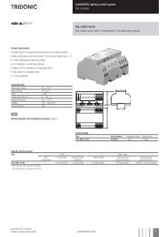
<strong>DALI</strong> power supply <strong>DALI</strong> PS / <strong>DALI</strong> PS1 / <strong>DALI</strong> PS2<br />
<strong>DALI</strong> PS, <strong>DALI</strong> PS1 and <strong>DALI</strong> PS2 are <strong>DALI</strong> power supply modules with a rated current of 200 mA (240 mA in the<br />
case of <strong>DALI</strong> PS2). The modules differ in their casing design; <strong>DALI</strong> PS and <strong>DALI</strong> PS2 are suitable for installation in<br />
switching cabinets; <strong>DALI</strong> PS1 is suitable for installation in suspended ceilings or cavities.<br />
<strong>DALI</strong> group controllers<strong>DALI</strong> GC / GC-A<br />
Two lighting groups can be controlled with the group controller (ON/OFF/DIM). Set-up (addressing) and assignment to<br />
the <strong>DALI</strong> groups can be performed by means of a simple switch sequence. In the case of the GC-A version,<br />
configuration via the switches is disabled to prevent unintentional reprogramming. The compact design enables the<br />
unit to be installed in a standard switch box.<br />
<strong>DALI</strong> scene controllers <strong>DALI</strong> SC / SC-A<br />
The scene controller enables four lighting scenes to be programmed and recalled.<br />
<strong>DALI</strong> Manual | 08-2013 | en<br />
10 / 93
.<br />
c<br />
<strong>DALI</strong> controllers of comfortDIM product series<br />
The scene controller enables four lighting scenes to be programmed and recalled.<br />
In the case of the SC-A version, configuration via the switches is disabled to prevent unintentional reprogramming.<br />
The compact design enables the unit to be installed in a standard switch box.<br />
<strong>DALI</strong> multicontroller<strong>DALI</strong> MC<br />
<strong>DALI</strong> MC has 4 inputs, the functions of which can be freely edited. Via the settable switching modes (short, long press;<br />
toggle; relay mode) a maximum of two options can be assigned to each input, of which one function can be activated in<br />
each case. Customer-specific programming is possible via the masterCONFIGURATOR (see Reference list)<br />
configuration software. The compact design enables the unit to be installed in a standard switch box.<br />
<strong>DALI</strong> TOUCHPANEL<br />
The <strong>DALI</strong> TOUCHPANEL 02 has selectable control panel functions for <strong>manual</strong> control of <strong>DALI</strong> lighting groups and<br />
<strong>DALI</strong> lighting scenes. Customer-specific programming is possible via the masterCONFIGURATOR (since version 2.6)<br />
(see Reference list) .<br />
<strong>DALI</strong> x/e-touchPANEL 02<br />
The x/e-touchPANEL 02 with its 7 inch colour touch screen is a lighting management system for up to 128 <strong>DALI</strong> units.<br />
The x/e-touchPANEL 02 contains user-friendly application software with a mode optimised for RGB colour lighting<br />
management.<br />
<strong>DALI</strong> Manual | 08-2013 | en<br />
11 / 93
.<br />
c<br />
<strong>DALI</strong> controllers of comfortDIM product series<br />
<strong>DALI</strong> sequencer module<strong>DALI</strong>-SQM<br />
The sequencer module sends broadcast-addressed scene calls at user-defined intervals (up to 16 different scenes).<br />
The factory-setting is that a sequence comprises 8 scenes. When the last scene is reached the cycle starts again from<br />
the beginning.<br />
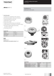
<strong>DALI</strong> MSensor 02<br />
The <strong>DALI</strong> MSensor 02 is a <strong>DALI</strong>-based sensor with ambient light control and presence detection. The <strong>DALI</strong> MSensor<br />
02 also has a receiver for infrared remote control. There are versions for installation in luminaires, ceilings and boxes<br />
and also for surface mounting.<br />
<strong>DALI</strong> RC and IR smart Controller<br />
These two remote controls extend the functionality of the <strong>DALI</strong> MSensor 02.<br />
With the user-friendly <strong>DALI</strong> RC remote control it is also possible to perform all the basic functions of the <strong>DALI</strong> MSensor<br />
<strong>DALI</strong> Manual | 08-2013 | en<br />
12 / 93
.<br />
c<br />
<strong>DALI</strong> controllers of comfortDIM product series<br />
With the user-friendly <strong>DALI</strong> RC remote control it is also possible to perform all the basic functions of the <strong>DALI</strong> MSensor<br />
02.<br />
<strong>DALI</strong> USB<br />
The <strong>DALI</strong> USB interface module enables the <strong>DALI</strong> installation to be set up and parametrised with the aid of a PC.<br />
<strong>Tridonic</strong> offers therefore the software masterCONFIGURATOR (see Reference list) to make it easier to put even<br />
complex <strong>DALI</strong> installations into operation.<br />
<strong>DALI</strong> RS232 Interface PS/S<br />
The <strong>DALI</strong> RS232 Interface PS/S combines a <strong>DALI</strong> interface module and a power supply module in one and the same<br />
device. The rated current of the power supply is 240 mA. Via the RS232 interface it is possible to put the <strong>DALI</strong> system<br />
into operation and to set its parameters. During normal operation the interface can be used for service purposes. The<br />
RS232 interface is accessed via an RJ45 socket. An optional connecting cable from the RJ45 socket to an RS232 plug<br />
is available as an accessory.<br />
Additional adapters (to USB for example) are available from various manufacturers.<br />
...<br />
<strong>DALI</strong> Manual | 08-2013 | en<br />
13 / 93
.<br />
c<br />
<strong>DALI</strong> interface modules<br />
<strong>DALI</strong> interface modules<br />
<strong>DALI</strong> DSI / DSI II<br />
The <strong>DALI</strong> DSI converter converts <strong>DALI</strong> commands into DSI signals so that DSI-based units can be integrated in <strong>DALI</strong><br />
lighting control systems.<br />
<strong>DALI</strong> Somfy animeo interface<br />
With this interface Somfy animeo IB+ motor controllers can be integrated in the <strong>DALI</strong> circuit. The <strong>DALI</strong> Somfy animeo<br />
interface can control up to four blinds independently. The blind positions (height and angle) are stored like lighting<br />
scenes. The lighting and the blind positions can be stored under one and the same scene.<br />
<strong>DALI</strong> 3-RM-C<br />
The <strong>DALI</strong>-3-RM-C relay module controller enables up to 3 standard contactors (24 V DC) to be controlled so that<br />
different loads can be switched via <strong>DALI</strong> commands.<br />
<strong>DALI</strong> RM<br />
The <strong>DALI</strong> RM relay module controller enables a contactor (12/24 V or 230V ) to be controlled so that different loads<br />
DC<br />
AC<br />
can be switched via <strong>DALI</strong> commands.<br />
<strong>DALI</strong> Manual | 08-2013 | en<br />
14 / 93
.<br />
c<br />
<strong>DALI</strong> devices<br />
<strong>DALI</strong> devices<br />
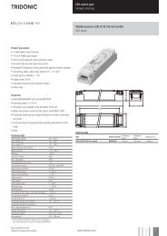
Electronic LED control gear<br />
LCAU 2x020/0048 L0x0 one4all<br />
LCAU 2x020/0048 L0x0 one4all control gear is digital dimmable electronic control gear for PREMIUM modules (SLE<br />
and DLE). LCAU 2x020/0048 L0x0 onel4all control gear offers control options via <strong>DALI</strong>, DSI and switchDIM. The<br />
control gear supports <strong>DALI</strong> Device Type 8 for tunable white. Colours can be set via xy coordinates or via the colour<br />
temperature. There are 16 scenes (predefined colour temperatures) preprogrammed in the control gear. These can be<br />
reprogrammed with the aid of the masterCONFIGURATOR.<br />
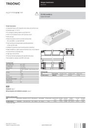
LCAI ECO one4all, C003. K350<br />
The LED control gear in the LCAI ECO one4all series are dimmable constant current devices with adjustable output<br />
currents. There are built-in versions (Linear and Compact) and remote versions (Compact with tool-less strain relief).<br />
LCAI ECO one4all has the option of control via <strong>DALI</strong>, DSI or switchDIM and automatically adjusts to the control signal.<br />
The control gear has various functions that can be set via <strong>DALI</strong>. Details can be found in the product data sheet or in<br />
the <strong>manual</strong>.<br />
LED control gear C003<br />
LED control gear C003 has three independent output channels for dimming light emitting diodes with 24 V.<br />
<strong>DALI</strong> Manual | 08-2013 | en<br />
15 / 93
.<br />
c<br />
<strong>DALI</strong> devices<br />
LED control gear K350<br />
LED control gear K350 is a constant current device for 350 mA LEDs and has three independent output channels.<br />
Electronic Fluorescent control gear<br />
PCA EXCEL one4all xitec II<br />
PCA EXCEL one4all lp xitec II and PCA ECO lp xitec II are digital dimmable electronic control gear for fluorescent<br />
lamps. PCA EXCEL one4all lp xitec II has the option of control via <strong>DALI</strong>, DSI, switchDIM or SMART and automatically<br />
adjusts to the control signal.<br />
It also has a large number of intelligent functions and is therefore suitable for a wide range of applications. PCA ECO lp<br />
xitec II has the option of control via <strong>DALI</strong>, DSI, switchDIM and SMART and is designed for use in building management<br />
systems.<br />
PCA ECO lp xitec II<br />
PCA ECO lp xitec II is digital dimmable electronic control gear for fluorescent lamps.<br />
PCA ECO lp xitec II has the option of control via <strong>DALI</strong>, DSI, switchDIM and SMART and is designed for use in building<br />
management systems.<br />
<strong>DALI</strong> Manual | 08-2013 | en<br />
16 / 93
.<br />
c<br />
<strong>DALI</strong> devices<br />
Electronic HID control gear<br />
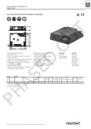
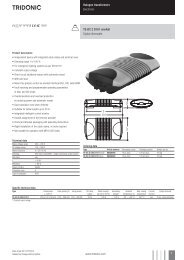
PCIS outdoor DIM B011<br />
Very durable HID ballasts designed for outdoor applications. The Interface of the PCIS outdoor DIM B011 ballasts<br />
enables <strong>DALI</strong>, DSI and StepDIM functionality. Depending on the used lamp these ballasts can dim down to 40% to<br />
save energy. Fixed output HID ballast with <strong>DALI</strong> / DSI interface.<br />
Electronic transformers<br />
TE one4all<br />
The TE one4all is an electronic safety transformer for low-voltage halogen lamps. It enables low-voltage halogen lamps<br />
to be integrated directly in the <strong>DALI</strong> circuit and can also fade them up and down.<br />
TE-DC 2 one4all<br />
The TE DC 2 one4all is an electronic safety transformer for low-voltage halogen lamps. It enables low-voltage halogen<br />
lamps to be integrated directly in the <strong>DALI</strong> circuit and can also fade them up and down.<br />
<strong>DALI</strong> Manual | 08-2013 | en<br />
17 / 93
.<br />
c<br />
<strong>DALI</strong> devices<br />
Phase dimmers<br />
<strong>DALI</strong> PCD 300 one4all<br />
<strong>DALI</strong> PCD 300 one4all is a digital leading-edge and trailing-edge phase dimmer for ceiling installation.<br />
They enable equipment such as electronic or magnetic transformers for low-voltage halogen lamps or incandescent<br />
lamps to be integrated in a <strong>DALI</strong> system.<br />
Connected load for <strong>DALI</strong> PCD 300 one4all: 30 VA – 300 VA.<br />
<strong>DALI</strong> PCD/S<br />
<strong>DALI</strong> PCD/S is a digital leading-edge and trailing-edge phase dimmer for mounting in switching cabinets.<br />
They enable equipment such as electronic or magnetic transformers for low-voltage halogen lamps or incandescent<br />
lamps to be integrated in a <strong>DALI</strong> system.<br />
Connected load for <strong>DALI</strong> PCD/S: 40 VA – 1000 VA.<br />
LED and Fluorescent control gear for emergency lighting<br />
EM PRO EZ-3<br />
LED emergency control gear for a wide range of fluorescent lamps with <strong>DALI</strong> interface and automatic test function.<br />
<strong>DALI</strong> Manual | 08-2013 | en<br />
18 / 93
.<br />
c<br />
<strong>DALI</strong> devices<br />
EM powerLED PRO EZ-3 1-2W<br />
Maintained LED emergency control gear 1 – 2W with <strong>DALI</strong> interface and automatic test function.<br />
EM powerLED PRO EZ-3 4W<br />
Non-maintained LED emergency control gear 4W with <strong>DALI</strong> interface and automatic test function.<br />
...<br />
<strong>DALI</strong> Manual | 08-2013 | en<br />
19 / 93
.<br />
c<br />
Miscellaneous<br />
Miscellaneous<br />
<strong>DALI</strong> Repeater<br />
The <strong>DALI</strong> Repeater is an amplifier module for refreshing the <strong>DALI</strong> signal. With the <strong>DALI</strong> Repeater it is possible to<br />
increase the maximum length of the <strong>DALI</strong> control line from 300 m to 600 m.<br />
...<br />
<strong>DALI</strong> Manual | 08-2013 | en<br />
20 / 93
.<br />
c<br />
comfortDIM product series in detail<br />
comfortDIM product series in detail<br />
This chapter provides details of the various comfortDIM products. The topics covered here include functions,<br />
connections and programming. For further information on the products please refer to the data sheets and the<br />
installation instructions.<br />
<strong>DALI</strong> power supply<br />
<strong>DALI</strong> PS / PS1/ PS2<br />
<strong>DALI</strong> PS, <strong>DALI</strong> PS1 and <strong>DALI</strong> PS2 are <strong>DALI</strong> power supply modules with a rated current of 200 mA or 240 mA (<strong>DALI</strong><br />
PS2). The modules differ in their casing design; <strong>DALI</strong> PS and <strong>DALI</strong> PS2 are suitable for installation in switching<br />
cabinets; <strong>DALI</strong> PS1 is suitable for installation in suspended ceilings or cavities.<br />
The interface of a <strong>DALI</strong> ballast needs a maximum of 2 mA; for 64 individual addresses this means a current of 128 mA.<br />
The remaining 72 mA (or 112 mA in the case of <strong>DALI</strong> PS2) can be used for supplying <strong>DALI</strong> control modules without<br />
their own power supply (<strong>DALI</strong> GC, <strong>DALI</strong> SC etc.).<br />
<strong>DALI</strong> PS2 Standby<br />
<strong>DALI</strong> PS2 Standby also has a built-in relay contact. To reduce standby losses, the built-in relay disconnects the<br />
ballasts from the power supply as soon as all the luminaires have been switched off.<br />
As soon as the <strong>DALI</strong> PS2 Standby detects that all the luminaires have been switched off it changes to standby mode<br />
after a user-definable delay and controls a built-in relay. With the aid of this relay the connected units can be<br />
disconnected from the power supply via a contactor. Only the <strong>DALI</strong> control modules are then still in the <strong>DALI</strong> circuit.<br />
As soon as a <strong>DALI</strong> control module sends a “Light ON” command the <strong>DALI</strong> PS2 Standby reverts to normal operating<br />
mode and connects the units back to the power supply. The parameters of the <strong>DALI</strong> PS2 Standby, such as delay,<br />
monitoring interval etc. can be set using the masterCONFIGURATOR configuration software (V1.12 or higher) (see<br />
Reference list).<br />
<strong>DALI</strong> Manual | 08-2013 | en<br />
21 / 93
.<br />
c<br />
<strong>DALI</strong> power supply<br />
Figure: Delay and monitoring intervals<br />
( 1 ) ( 2 ) ( 3 ) ( 4 ) ( 5 )<br />
Status request for<br />
the units from the<br />
<strong>DALI</strong> PS2 Standby<br />
Power<br />
Supply<br />
detects all<br />
units off<br />
Switch-off delay<br />
expires<br />
(parameter: Switch<br />
off delay)<br />
Power Supply<br />
switches to standby<br />
mode (relay is<br />
opened)<br />
"ON" command from a control<br />
module; Power Supply leaves<br />
standby mode (relay closes)<br />
...<br />
<strong>DALI</strong> Manual | 08-2013 | en<br />
22 / 93
.<br />
c<br />
<strong>DALI</strong> group controllers: <strong>DALI</strong> GC & GC-A<br />
<strong>DALI</strong> group controllers: <strong>DALI</strong> GC & GC-A<br />
Description<br />
<strong>DALI</strong>-GC is a module that enables dimming commands to be sent to two groups (groups A and B) on the <strong>DALI</strong> circuit.<br />
Any standard momentary switch can be connected to the module. Its compact design means that <strong>DALI</strong>-GC can be<br />
installed together with the standard momentary switches in a flush-mounted box, so set-up of the <strong>DALI</strong> circuit can be<br />
decentralised. Either individual switches or UP/DOWN switches can be used for controlling the groups. The controlled<br />
groups are set on a rotary switch on the module.<br />
The <strong>DALI</strong> GC module is multi-master-compatible so several control modules can be used in a <strong>DALI</strong> circuit. It is also<br />
possible to address and group simple <strong>DALI</strong> circuits with the aid of <strong>DALI</strong>-GC.<br />
<strong>DALI</strong>-GC-A is similar to <strong>DALI</strong>-GC. The only difference is that the programming mode is not activated in <strong>DALI</strong>-GC-A.<br />
This prevents the <strong>DALI</strong> units from being reprogrammed unintentionally via the switches.<br />
Connection<br />
The <strong>DALI</strong>-GC switch module is connected directly to the <strong>DALI</strong> control line and does not need a separate power supply.<br />
It is powered via the <strong>DALI</strong> circuit (current draw = 6 mA). It can be connected to the <strong>DALI</strong> circuit with either polarity.<br />
Either single momentary switches or UP/DOWN momentary switches can be used for controlling a group. If a single<br />
switch is used the UP/DOWN connections are simply connected in parallel. It is also possible to operate the two<br />
groups (A and B) with different types of momentary switch; for example group A with UP/DOWN switches and group B<br />
with a single switch.<br />
Figure: <strong>DALI</strong>-GC momentary switch connection<br />
Single switch connection<br />
UP/DOWN switch connection<br />
<strong>DALI</strong> Manual | 08-2013 | en<br />
23 / 93
.<br />
c<br />
<strong>DALI</strong> group controllers: <strong>DALI</strong> GC & GC-A<br />
½ CAUTION!<br />
The <strong>DALI</strong> circuit is not SELV. This means that the switches and cabling must be suitable for mains voltage.<br />
The connection leads between the momentary switches and the <strong>DALI</strong>-GC must not be lengthened!<br />
Basic functions<br />
Switch group on<br />
Connect standard momentary switch (single switch or double switch) to the <strong>DALI</strong> GC<br />
Press single momentary switch or UP button of double momentary switch briefly<br />
→ Luminaires will be dimmed to maximum<br />
→ Group is switched on<br />
Switch group off<br />
Press single momentary switch or UP button of double momentary switch<br />
→ Luminaires will be switched off<br />
→ Group is switched off<br />
Dimm groups<br />
Hold down single momentary switch or UP/DOWN button of double momentary switch<br />
→ Luminaires will be switched on (if they were switched off before)<br />
→ Luminaires will be dimmed<br />
Overview of switch functions<br />
Table: Momentary switch functions double momentary switch<br />
Depress time UP button Depress time DOWN button Function<br />
40 to 300 ms On to max<br />
40 to 300 ms Off<br />
> 300 ms > 300 ms On (if necessary) / dim<br />
<strong>DALI</strong> Manual | 08-2013 | en<br />
24 / 93
.<br />
c<br />
<strong>DALI</strong> group controllers: <strong>DALI</strong> GC & GC-A<br />
Table: Momentary switch functions single switch<br />
Depress time single switch<br />
Function<br />
40 to 300 ms On to max / Off<br />
> 300 ms On (if necessary) / dim<br />
Group assignment<br />
A rotary switch on the back of the module is used for group assignment. The switch setting shown corresponds to<br />
group A. Group B is the group immediately following group A.<br />
Table: Group assignment<br />
Rotary switch setting Group switch 1 Group switch 2<br />
0 Broadcast 1<br />
1 1 2<br />
2 2 3<br />
3...9 3...9 4...10<br />
A...F 10...15 11...16<br />
Example:<br />
Rotary switch setting = 3, therefore:<br />
Switch 1 = group 3, switch 2 = group 4<br />
Programming<br />
With the <strong>DALI</strong>-GC it is also possible to address and configure simple <strong>DALI</strong> installations. The programming mode is not<br />
integrated in <strong>DALI</strong>-GC-A so there is no chance of reprogramming the <strong>DALI</strong> units by mistake via the momentary<br />
switches.<br />
<strong>DALI</strong> Manual | 08-2013 | en<br />
25 / 93
.<br />
c<br />
<strong>DALI</strong> group controllers: <strong>DALI</strong> GC & GC-A<br />
Start programming mode without deletion of addresses (expansion of the system)<br />
Connect standard momentary switch to <strong>DALI</strong> GC<br />
Choose a button and hold down (>10 s)<br />
→ A beep will sound<br />
Release button briefly (1s)<br />
→ A beep will sound again<br />
Hold button down (1s)<br />
→ Two beeps will sound<br />
Release button<br />
→ Device switches to programming mode<br />
→ Current settings (group assignment) won't be deleted<br />
Figure: Programming mode without deleting the addresses<br />
Start programming mode with deletion of addresses (new installation)<br />
Connect standard momentary switch to <strong>DALI</strong> GC<br />
Choose a button and hold down (>10 s)<br />
→ A beep will sound<br />
Release button briefly (1s)<br />
→ A beep will sound again<br />
Hold button down (>3s)<br />
→ Two beeps will sound (after 1s)<br />
→ Three more beeps will sound (after 3s)<br />
Release button<br />
→ Device switches to programming mode<br />
→ Current settings (group assignment) will be deleted<br />
<strong>DALI</strong> Manual | 08-2013 | en<br />
26 / 93
.<br />
c<br />
<strong>DALI</strong> group controllers: <strong>DALI</strong> GC & GC-A<br />
Figure: Programming mode with deletion of addresses<br />
I NOTICE<br />
In programming mode the system first searches for available <strong>DALI</strong> devices in the <strong>DALI</strong> circuit. The devices are<br />
addressed as follows:<br />
In programming mode with deletion all devices will be automatically addressed<br />
In programming mode without deletion only newly detected devices are addressed<br />
During the search operation all the detected luminaires are faded to maximum. When the search has been<br />
completed one luminaire (the one selected) will remain at maximum and all the others will be faded to the lowest<br />
value.<br />
Selecting luminaires<br />
To attach a luminaire to a group, the luminaire must be selected first.<br />
Choose a button of the momentary switch<br />
Press button briefly to select a luminaire<br />
→ Selected luminaire is faded to maximum<br />
→ All other luminaires are dimmed to minimum<br />
Press button again to select another luminaire<br />
I NOTICE<br />
A single luminaire can contain more than one device. If this is the case all devices in the luminaire must be selected<br />
separately.<br />
The luminaires are selected in the sequence in which they are found. When you come to the last luminaire in the<br />
sequence, the next one selected will be the first luminaire in the sequence again. A selected luminaire can now be<br />
assigned to a group.<br />
Assigning a selected luminaire to a group<br />
If a luminaire is assigned to a certain group it reacts to fade commands that come from momentary switches of the<br />
same group. The group assigned can be stored in the selected <strong>DALI</strong> device.<br />
Make sure that the right luminaire is selected<br />
Choose a button that is assigned to the right group<br />
<strong>DALI</strong> Manual | 08-2013 | en<br />
27 / 93
.<br />
c<br />
<strong>DALI</strong> group controllers: <strong>DALI</strong> GC & GC-A<br />
Choose a button that is assigned to the right group<br />
Hold button down (>3s)<br />
→ A beep will sound<br />
→ The group assigned will be stored in the <strong>DALI</strong> device<br />
→ Luminaire will react to fade commands coming from the chosen button<br />
The group assigned to a switch (rotary switch setting) can be stored in the selected <strong>DALI</strong> device by pressing the<br />
appropriate momentary switch (for longer than 3 seconds; you will hear a beep). This means that the luminaire will then<br />
react to fade commands from this momentary switch.<br />
Figure: Group assignment<br />
Removing a luminaire from a group<br />
Make sure that the right luminaire is selected<br />
Choose a button that is assigned to the right group<br />
Hold button down (>6s)<br />
→ First beep will sound (after 3s)<br />
→ Second beep will sound (after another 3s)<br />
→ The group assigned of the button will be deleted<br />
→ Luminaire will not react anymore to fade commands coming from the chosen button<br />
Figure: Removing a luminaire from a group<br />
<strong>DALI</strong> Manual | 08-2013 | en<br />
28 / 93
.<br />
c<br />
<strong>DALI</strong> group controllers: <strong>DALI</strong> GC & GC-A<br />
Finish programming mode<br />
Hold button down (>9s)<br />
→ First beep will sound (after 3s)<br />
→ Second beep will sound (after another 3s)<br />
→ Third beep will sound (after another 3s)<br />
Release button<br />
→ Programming mode is finished<br />
→ All buttons in the system are back in their normal state<br />
Figure: Finish programming mode<br />
Example: Multiple independent small offices on the same <strong>DALI</strong> line<br />
Requirement<br />
On/off switching via switches<br />
Dimming of two groups (window luminaires and corridor luminaires)<br />
<strong>DALI</strong> Manual | 08-2013 | en<br />
29 / 93
.<br />
c<br />
<strong>DALI</strong> group controllers: <strong>DALI</strong> GC & GC-A<br />
Figure: Overview of a small office set-up (left room A / right room B)<br />
Table: <strong>DALI</strong>-GC assignment<br />
Room A<br />
Room B<br />
Window group Group 1 Group 3<br />
Corridor group Group 2 Group 4<br />
<strong>DALI</strong>-GC Rotary switch setting 1 (Groups 1+2):<br />
Group 1 => Switch for window row<br />
Group 2 => Switch for corridor row<br />
Rotary switch setting 3 (Groups 3+4):<br />
Group 3 => Switch for window row<br />
Group 4 => Switch for corridor row<br />
...<br />
<strong>DALI</strong> Manual | 08-2013 | en<br />
30 / 93
.<br />
c<br />
<strong>DALI</strong> scene controllers: <strong>DALI</strong>-SC & SC-A<br />
<strong>DALI</strong> scene controllers: <strong>DALI</strong>-SC & SC-A<br />
Description<br />
<strong>DALI</strong>-SC is a module that enables scene selection commands for up to four scenes (A, B, C, D) to be sent to the <strong>DALI</strong><br />
circuit. Any standard momentary switch can be connected to the module. Its compact design means that <strong>DALI</strong>-SC can<br />
be installed together with the standard momentary switches in a flush-mounted box, so set-up of the <strong>DALI</strong> circuit can<br />
be decentralised.<br />
The scenes are set on a rotary switch on the module.<br />
The <strong>DALI</strong> SC module is multi-master-compatible so several control modules can be used in a <strong>DALI</strong> circuit.<br />
<strong>DALI</strong>-SC-A is similar to <strong>DALI</strong>-SC. The only difference is that the programming mode is not activated in <strong>DALI</strong>-SC-A.<br />
This prevents the <strong>DALI</strong> units from being reprogrammed unintentionally via the momentary switches.<br />
Connection<br />
The <strong>DALI</strong>-SC scene module is connected directly to the <strong>DALI</strong> circuit and does not need a separate power supply. It is<br />
powered via the <strong>DALI</strong> circuit (current draw = 6 mA). It can be connected to the <strong>DALI</strong> circuit with either polarity.<br />
Figure: <strong>DALI</strong>-SC switch connection<br />
½ CAUTION!<br />
The connection leads between the momentary switches and the <strong>DALI</strong>-SC must not be lengthened. The <strong>DALI</strong> circuit<br />
is not SELV. This means that the switches and cabling must be suitable for mains voltage.<br />
<strong>DALI</strong> Manual | 08-2013 | en<br />
31 / 93
.<br />
c<br />
<strong>DALI</strong> scene controllers: <strong>DALI</strong>-SC & SC-A<br />
Basic functions<br />
Press momentary switch briefly<br />
→ The scene which is assigned to the momentary switch will be retrieved<br />
A scene is assigned to each of the four momentary switches. The scene selections are broadcast to all the luminaires<br />
on the <strong>DALI</strong> circuit.<br />
Table: Switch function<br />
Switch depression<br />
Function<br />
40 ms...1 s Selection of the scene assigned to the switch<br />
Scene assignment<br />
A rotary switch on the back of the module is used for scene assignment. The switch setting shown corresponds to<br />
scene A. Scenes B, C and D immediately follow scene A.<br />
Table: Scene assignment<br />
Rotary switch setting Scene switch 1 Scene switch 4 Scene switch 3 Scene switch 4<br />
1 1 2 3 4<br />
2 2 3 4 5<br />
3 3 4 5 6<br />
4...9 4...9 5...10 6...11 7...12<br />
A...F 10...15 11...16 12...1 13...2<br />
0 16 1 2 3<br />
Example:<br />
Switch setting = 3, therefore:<br />
Switch 1 = scene 3, switch 2 = scene 4, switch 3 = scene 5, switch 4 = scene 6<br />
<strong>DALI</strong> Manual | 08-2013 | en<br />
32 / 93
.<br />
c<br />
<strong>DALI</strong> scene controllers: <strong>DALI</strong>-SC & SC-A<br />
Switch 1 = scene 3, switch 2 = scene 4, switch 3 = scene 5, switch 4 = scene 6<br />
Programming<br />
Save scene<br />
Hold down momentary switch (>10s)<br />
→ A beep will sound<br />
Press momentary switch (1s)<br />
→ Current light value of all luminaires will be stored as scene value<br />
→ Scene number of the momentary switch will be assigned to the scene<br />
→ Scene can be activated with the chosen momentary switch<br />
I NOTICE<br />
The light value can be changed with any <strong>DALI</strong> control (e.g. <strong>DALI</strong> GC).<br />
The programming mode is not integrated in <strong>DALI</strong>-SC-A so there is no chance of reprogramming the <strong>DALI</strong> units by<br />
mistake via the switches.<br />
Figure: Scene assignment<br />
Example: Conference room<br />
Requirement<br />
On/off switching via switches<br />
Dimming of two groups (linear luminaires and low-voltage halogen spotlights)<br />
Retrieval of user-defined lighting scenes (e.g. the presentation scene)<br />
<strong>DALI</strong> Manual | 08-2013 | en<br />
33 / 93
.<br />
c<br />
<strong>DALI</strong> scene controllers: <strong>DALI</strong>-SC & SC-A<br />
Figure: Overview of a conference room set-up<br />
Table: <strong>DALI</strong>-GC and SC assignment<br />
...<br />
Linear luminaires Group 1<br />
Halogen spotlights Group 2<br />
Conference room<br />
<strong>DALI</strong>-GC Rotary switch setting 1 (Groups 1+2):<br />
Group 1 => Switch for linear luminaires<br />
Group 2 => Switch for halogen spotlights<br />
<strong>DALI</strong>-SC Rotary switch setting 1 (Scenes 1-4):<br />
Scene 1 => Light off<br />
Scene 2 => Light 100%<br />
Scene 3 => Presentation<br />
Scene 4 => Meeting<br />
<strong>DALI</strong> Manual | 08-2013 | en<br />
34 / 93
.<br />
c<br />
<strong>DALI</strong> multi controller: <strong>DALI</strong> MC<br />
<strong>DALI</strong> multi controller: <strong>DALI</strong> MC<br />
Description<br />
The <strong>DALI</strong> MC is a multifunctional control module for the <strong>DALI</strong> circuit. It has four independent inputs with freely<br />
configurable functions. Any standard switches compatible with mains voltage can be connected to the module. It is also<br />
possible to control the inputs of the <strong>DALI</strong> MC via relays.<br />
There is also the option of providing a power supply monitoring system with the <strong>DALI</strong> MC. When the power supply<br />
returns a predefined lighting status is retrieved by the <strong>DALI</strong> MC. Its compact design means that the <strong>DALI</strong> MC can be<br />
installed together with standard switches in a flush-mounted box. The <strong>DALI</strong> circuit can therefore be decentralised.<br />
The four inputs are configured by means of masterCONFIGURATOR (see Reference list).<br />
The <strong>DALI</strong> MC module is multi-master-compatible so several control modules can be used in a <strong>DALI</strong> circuit.<br />
Connection<br />
The <strong>DALI</strong> MC switch module is connected directly to the <strong>DALI</strong> control line and does not need a separate power supply.<br />
It is powered via the <strong>DALI</strong> circuit (current draw = 6 mA). It can be connected to the <strong>DALI</strong> circuit with either polarity.<br />
½ CAUTION!<br />
The connection leads between the switch or button and the <strong>DALI</strong> MC must not be longer than 50 cm.<br />
The <strong>DALI</strong> circuit is not SELV. This means that the switches and cabling must be suitable for mains voltage.<br />
<strong>DALI</strong> Manual | 08-2013 | en<br />
35 / 93
.<br />
c<br />
<strong>DALI</strong> multi controller: <strong>DALI</strong> MC<br />
Function<br />
The behaviour of each of the four inputs can be defined with the aid of the masterCONFIGURATOR software. Possible<br />
settings are:<br />
The input functions as<br />
a push to make switch<br />
a standard switch<br />
a changeover switch<br />
a stairwell switch<br />
a push to make switch that calls up a predefined sequence of <strong>DALI</strong> commands (macro)<br />
In addition to defining the function you can set further parameters to select the destination address for which the<br />
function is intended (broadcast, group or individual address) and the type of <strong>DALI</strong> command to be performed.<br />
Example: On/off switch<br />
Destination address Group 1<br />
Function<br />
<strong>DALI</strong> command<br />
Switch<br />
“Recall max. Level” when switched on and “OFF” when switched off<br />
Configuration by masterCONFIGURATOR<br />
The masterCONFIGURATOR has its own separate documentation (see Reference list).<br />
<strong>DALI</strong> Manual | 08-2013 | en<br />
36 / 93
.<br />
c<br />
<strong>DALI</strong> multi controller: <strong>DALI</strong> MC<br />
Table: Explanation of parameters for functions<br />
Function<br />
1) Push-button:<br />
short or long = 1 * command X<br />
2) Push-button:<br />
short = 1 * command X,<br />
long = 1 * command X then 1 *<br />
command Y<br />
3) Push-button:<br />
short = 1 * command X,<br />
long = 1 * command X then<br />
repeatedly command Y<br />
Description<br />
Briefly pressing or holding down the push-button will send command X one<br />
time.<br />
» Briefly pressing the push-button will send command X one time.<br />
» Holding down the push-button will send command X once, and then<br />
command Y once.<br />
» Briefly pressing the push-button will send command X one time.<br />
» Holding down the push-button will send command X once, and then<br />
command Y repeatedly.<br />
4) Push-button:<br />
short = 1* command X,<br />
long = repeatedly command Y<br />
»<br />
»<br />
Briefly pressing the push-button will send command X one time.<br />
Holding down the push-button will repeatedly send command Y.<br />
5) Push-button (toggle):<br />
short or long = toggle between<br />
command X and Y<br />
6) Push-button (toggle):<br />
short or long = toggle between<br />
command X and Y,<br />
lighting-based<br />
7) Push-button (dimming key):<br />
short = toggle between command<br />
X and Y,<br />
long = dimming, lighting-based<br />
Briefly pressing or holding down the push-button will alternate between sending<br />
commands X and Y.<br />
Briefly pressing or holding down the push-button will alternate between sending<br />
commands X and Y. The command sent in each case depends on the status of<br />
the lighting:<br />
» If the lighting was previously switched off, command X is sent.<br />
» If the lighting was previously switched on, command Y is sent.<br />
SwitchDIM mode<br />
» Briefly pressing on the dimming key will alternate between sending<br />
commands X and Y. The command sent in each case depends on the<br />
status of the lighting.<br />
» If the lighting was previously switched off, command X is sent.<br />
» If the lighting was previously switched on, command Y is sent. Holding<br />
down the dimmer switch dims or brightens the lighting.<br />
8) Switch:<br />
close = command X,<br />
open = command Y<br />
»<br />
»<br />
When the switch is closed, command X is sent.<br />
When the switch is opened, command Y is sent.<br />
9) Changeover switch:<br />
close = command X,<br />
open = command Y,<br />
lighting-based<br />
Each time the switch is pressed, the commands X and Y are sent in alternating<br />
order. The command sent in each case depends on the status of the lighting:<br />
» If the lighting was previously switched off, command X is sent.<br />
» If the lighting was previously switched on, command Y is sent.<br />
<strong>DALI</strong> Manual | 08-2013 | en<br />
37 / 93
.<br />
c<br />
<strong>DALI</strong> multi controller: <strong>DALI</strong> MC<br />
10) Stairwell function:<br />
close = command X, start run-on<br />
time, run-on time elapsed =<br />
command Y<br />
If the push-button is pressed, command X is sent and the run-on time starts.<br />
Once the run-on time has elapsed, command Y is sent.<br />
Table: Macro description<br />
Macro<br />
Macro 1: Go home<br />
Macro 2: MSensor<br />
automatic<br />
Macro 3:<br />
Sequential scene<br />
recall<br />
Macro 4: Dynamic<br />
scene<br />
Macro 5:<br />
<strong>DALI</strong>-Reset<br />
Macro 6: e-Power<br />
ON Level<br />
Macro 7: PCA<br />
compatibility<br />
Macro 8:<br />
User-defined <strong>DALI</strong><br />
commands<br />
Description<br />
Delayed light off (slow fade down)<br />
Lighting control for the selected <strong>DALI</strong> MSensor is activated<br />
The next scene is called up each time button connected to the input is pressed. At the end of<br />
the sequence the process starts again from the beginning.<br />
Pressing the button calls up a sequence of four scenes. The cross-fade time and dwell time<br />
can be freely defined for each scene.<br />
Reset for the defined devices. As an option all the <strong>DALI</strong> addresses can be deleted<br />
Sets the Power ON Level of the <strong>DALI</strong> ballast to the predefined value. <strong>DALI</strong> devices that do<br />
not support this function ignore the command<br />
Sets the “PCA compatibility” parameter in PCA EXCEL lp devices of generation xitec I to the<br />
predefined value. <strong>DALI</strong> devices that do not support this function ignore the command<br />
This macro executes a COT file that can be created by the user.<br />
For an explanation of the commands see Appendix / Important <strong>DALI</strong> parameters and <strong>DALI</strong> commands.<br />
Default setting<br />
The <strong>DALI</strong> MC has the following factory default input settings:<br />
<strong>DALI</strong> Manual | 08-2013 | en<br />
38 / 93
.<br />
c<br />
<strong>DALI</strong> multi controller: <strong>DALI</strong> MC<br />
Table 3: Default settings<br />
Input 1 Input 2 Input 3 Input 4<br />
Destination<br />
address<br />
Broadcast Broadcast Broadcast Broadcast<br />
Function<br />
Button:<br />
CmdX on press,<br />
repeats CmdY on long<br />
press<br />
Button:<br />
CmdX on press,<br />
repeats CmdY on long<br />
press<br />
Button:<br />
sends CmdX<br />
Macro 2:<br />
MSensor automatic<br />
CmdX RECALL MAX OFF RECALL<br />
SCENE 1<br />
-<br />
CmdY STEP UP STEP DOWN - -<br />
<strong>DALI</strong> Manual | 08-2013 | en<br />
39 / 93
.<br />
c<br />
<strong>DALI</strong> multi controller: <strong>DALI</strong> MC<br />
Example: Conference room with <strong>DALI</strong> MSensor and <strong>DALI</strong> MC<br />
Requirement<br />
Switch on via momentary switch<br />
Switch off via motion detector (off-only function)<br />
Daylight-dependent control of illuminance<br />
Retrieval of user-defined lighting scenes (e.g. the presentation scene)<br />
<strong>DALI</strong> Manual | 08-2013 | en<br />
40 / 93
.<br />
c<br />
<strong>DALI</strong> multi controller: <strong>DALI</strong> MC<br />
Figure: Overview of a conference room set-up<br />
Table: Assignment of <strong>DALI</strong> MSensor and <strong>DALI</strong> MC<br />
Controls<br />
Assignment<br />
...<br />
<strong>DALI</strong> MSensor Luminaire group: Group 1<br />
Rotary switch setting 1 (Groups 1):<br />
<strong>DALI</strong> MC Input 1:<br />
Destination address: Broadcast<br />
Function: Macro 2: MSensor automatic<br />
Inputs 2-4:<br />
Destination address: Broadcast<br />
Function: Button<br />
Command: Go to Scene 1-3<br />
<strong>DALI</strong> Manual | 08-2013 | en<br />
41 / 93
.<br />
c<br />
<strong>DALI</strong> TOUCHPANEL 02<br />
<strong>DALI</strong> TOUCHPANEL 02<br />
Description<br />
The <strong>DALI</strong>-TOUCHPANEL 02 is a multi-functional device for the <strong>DALI</strong> circuit. It combines the functions of <strong>DALI</strong>-GC and<br />
<strong>DALI</strong>-SC in a single module and has six freely definable buttons. The six buttons are configured using the<br />
masterCONFIGURATOR (since V2.6) (see Reference list).<br />
The following configurations are possible:<br />
On/off switching of individual addresses, groups or broadcast<br />
Up/down fading of individual addresses, groups or broadcast<br />
Scene selections<br />
The <strong>DALI</strong> TOUCHPANEL 02 offers a high degree of design flexibility. The user interface can be customized with<br />
interchangeable layout cards.<br />
The <strong>DALI</strong> TOUCHPANEL 02 is multi-master-compatible, which means that several control modules can be installed in<br />
parallel in a <strong>DALI</strong> system.<br />
Via the software masterCONFIGURATOR (since V2.6) it is possible to configure the panel for tunable white<br />
applications. The layout is configurable to control individual addresses, groups or broadcast.<br />
<strong>DALI</strong> Manual | 08-2013 | en<br />
42 / 93
.<br />
c<br />
<strong>DALI</strong> TOUCHPANEL 02<br />
Connection<br />
The <strong>DALI</strong> TOUCHPANEL 02 is connected directly to the <strong>DALI</strong> circuit and does not need a separate power supply. It is<br />
powered via the <strong>DALI</strong> circuit (current draw = 6 mA in normal operation and 10 mA in service mode). It can be<br />
connected to the <strong>DALI</strong> circuit with either polarity.<br />
Basic functions<br />
Figure: Button assignments of the factory layout<br />
1) Scene buttons:<br />
Calling up scenes 1-3<br />
2) Group buttons:<br />
Controlling assigned <strong>DALI</strong> devices or <strong>DALI</strong> groups.<br />
Short press: ON, OFF<br />
Long press: Dimming<br />
3) Finder LED:<br />
Red LED to find the panel in the dark.<br />
Long press: LED on/off<br />
Figure: Button assignments of the tunable white layout<br />
1) On-/Off button:<br />
Turning the Light on or OFF<br />
2) Dim whell:<br />
Recall of discrete dim calues by pressing on any position of the dim wheel.<br />
Dimming by sliding along the dim wheel.<br />
3) Finder LED:<br />
Red LED to find the panel in the dark.<br />
Long press: LED on/off<br />
4) Tunable White button:<br />
Change of the color temperature along the planckian locus via the buttons on<br />
the right and left side. Adjusting to 4,500 K by pressing the button in the middle.<br />
Configuration by software<br />
The masterCONFIGURATOR (since V2.6) software can be used to assign each of the buttons on the<br />
<strong>DALI</strong>-TOUCHPANEL 02. The <strong>DALI</strong> circuit can also be configured with the masterCONFIGURATOR (addressing,<br />
grouping, etc.). In addition to the masterCONFIGURATOR (since V2.6) software you will need a <strong>DALI</strong> USB for the<br />
connection between the computer and the <strong>DALI</strong> circuit.<br />
The masterCONFIGURATOR has its own separate documentation (see Reference list).<br />
<strong>DALI</strong> Manual | 08-2013 | en<br />
43 / 93
.<br />
c<br />
<strong>DALI</strong> TOUCHPANEL 02<br />
Table: Parameters for the dimming mode<br />
Dimming mode selection Short press Long press<br />
Toggle ON/OFF<br />
Toggles between the selected ON command and<br />
OFF command<br />
Dim up only Ignored On (if necessary) / fade up<br />
Dim up and on for short press Perform the selected ON command On (if necessary) / fade up<br />
Dim down only Ignored Fade down<br />
Dim down and off for short<br />
press<br />
Perform the selected OFF command<br />
Fade down<br />
Toggle up/down Ignored Toggle between fade up and<br />
fade down<br />
Toggle up/down and on/off for<br />
short press<br />
Toggles between the selected ON command and<br />
OFF command<br />
Toggle between fade up and<br />
fade down<br />
I NOTICE<br />
Selecting ON or OFF in dimming mode not only allows you to switch the lighting on or off, you can also select which<br />
specific command for ON or OFF will be sent. ON and OFF are therefore variables.<br />
Example: Configuring the scene 1 button<br />
Logical address<br />
Dimming mode<br />
Broadcast<br />
toggle ON/OFF<br />
ON/OFF command ON command: “Go to scene 1” / OFF command: “Go to scene 1”<br />
Each time the button is pressed the command “Go to scene 1” is sent.<br />
Example: Conference room Requirement<br />
Requirements<br />
On/off switching at the door<br />
Dimming of all the lights (broadcast) at the control panel near the window<br />
Retrieval of user-defined lighting scenes (e.g. the presentation scene) at the control panel near the window<br />
<strong>DALI</strong> Manual | 08-2013 | en<br />
44 / 93
.<br />
c<br />
<strong>DALI</strong> TOUCHPANEL 02<br />
Figure: Overview of a conference room set-up<br />
Table: <strong>DALI</strong>-SC and TOUCHPANEL assignment<br />
Linear luminaires Group 1<br />
Halogen spotlights Group 2<br />
Conference room<br />
<strong>DALI</strong>-SC<br />
(control panel near door)<br />
<strong>DALI</strong>-TOUCHPANEL<br />
(control panel near window)<br />
Rotary switch position 1 (scene 1-4):<br />
Scene 1 => Light off<br />
Scene 2 => Light 100%<br />
Scenes 3 and 4 => not used<br />
Touchpanel layout 1:<br />
Scene 1 => Light off<br />
Scene 2 => Light 100%<br />
Scene 3 => Presentation<br />
Up button => Fade up both groups<br />
Down button => Fade down both groups<br />
OFF button => Switch off the lighting<br />
...<br />
<strong>DALI</strong> Manual | 08-2013 | en<br />
45 / 93
.<br />
c<br />
<strong>DALI</strong> x/e-touchPANEL 02<br />
<strong>DALI</strong> x/e-touchPANEL 02<br />
Basic, Colour, Plug Operating Modes<br />
Design and functions<br />
In the Basic, Colour and Plug operating mode the x/e-touchPANEL is an operating device and controller for <strong>DALI</strong><br />
lighting systems. The x-touch software that is controlled using a colour touch-screen is integrated into the<br />
x/e-touchPANEL. It is possible to use it in combination with comfortDIM series controllers.<br />
The x-touch software provides the following functions:<br />
Operating modes<br />
» Basic for white light applications<br />
» Colour for RGBW applications<br />
» Plug for simple RGBW applications with preconfigured operating devices where the addressing is already<br />
set using coded connectors<br />
Configuration of<br />
» 16 scenes<br />
» 99 light sources<br />
» 7 time-controlled schedules<br />
» 1 calendar-controlled schedule list<br />
» DT 8 (Tunable White)<br />
Real-time clock/calendar<br />
Configuration of the buttons for <strong>manual</strong> call-up<br />
Design of the buttons for <strong>manual</strong> call-up<br />
Manual switching and dimming<br />
Frame light and adjustable display light<br />
Communication via interfaces:<br />
» USB<br />
» Ethernet (TCP/IP)<br />
Table: Properties x/e-touchPANEL<br />
Property<br />
x/e-touchPANEL<br />
Number of <strong>DALI</strong> lines 2<br />
Connection<br />
Bus supply<br />
Interfaces<br />
Frame light<br />
Display light<br />
Maximum 128 <strong>DALI</strong> operating devices<br />
External<br />
USB, Ethernet<br />
yes<br />
Always ON or automatically dimmed 2 min. after last activation.<br />
<strong>DALI</strong> Manual | 08-2013 | en<br />
46 / 93
.<br />
c<br />
<strong>DALI</strong> x/e-touchPANEL 02<br />
x-touch software<br />
The following explanations will help you understand the x-touch<br />
software.<br />
Tale: Designation x-touch software<br />
Designation<br />
Operating<br />
device<br />
Group (G)<br />
Zone (Z)<br />
Scene (S)<br />
Sequence<br />
(SQ)<br />
Day plan<br />
(SDL)<br />
Week plan<br />
(SDLL)<br />
Scheduler<br />
Meaning<br />
<strong>DALI</strong> operating device<br />
The x-touch software communicates with the operating devices (max. 64 per <strong>DALI</strong> line) via groups<br />
(max. 16).<br />
A group can be switched and dimmed individually. Groups can also include EM, HID, LV, INC,<br />
CONF, LED or Somfy operating devices.<br />
Zones are only used in the Colour operating mode. One zone consists of four predefined groups<br />
representing the colours red, green, blue and white.<br />
A scene is used to save a lighting situation defined by the setting of one or several groups.<br />
Several scenes are saved in a time-specific order in a sequence.<br />
One or several sequences and/or scenes are saved in a time-specific order in a schedule. A<br />
schedule starts automatically every 24 hours at a preset time of the day.<br />
Each schedule is assigned to one weekday. In this way, a schedule list is created for the<br />
calendar-controlled, uninterruptible automation of lighting situations.<br />
When Scheduler is activated, it appears in the Home menu and enables a sequence, schedule list<br />
and schedule to be controlled <strong>manual</strong>ly (Start, Pause, Stop and Off).<br />
Basic operating mode<br />
Typical application examples for the Basic operating mode are rooms where mostly white light is used, e.g. public<br />
rooms, production halls, restaurants and hotels.<br />
You can define a maximum of<br />
16 groups with a total of 128 devices<br />
16 scenes<br />
99 sequences<br />
7 schedules<br />
1 schedule list<br />
<strong>DALI</strong> Manual | 08-2013 | en<br />
47 / 93
.<br />
c<br />
<strong>DALI</strong> x/e-touchPANEL 02<br />
Colour operating mode<br />
All colours of the RGB colour space are the result of the addition of the basic colours red, green and blue (RGB). For a<br />
better representation of white light an additional white light source is used (RGBW colour mixing).The colour control of<br />
a lighting system is performed in the Colour operating mode. The Colour operating mode is different from the standard<br />
Basic operating mode with respect to the grouping of the operating devices.<br />
In the x-touch software, each RGB-/RGBW operating device is assigned to the colour scale (red, green, blue, white) of<br />
a zone. Four zones with 4 colour scales are available. The colour scale of a zone corresponds to a group. In the Home<br />
menu, the white light can be switched and dimmed via groups 1 to 4.<br />
The table shows the assignment of the 16 groups to the four colours of the individual zones. Zone assignment is<br />
automatically controlled by the software.<br />
W(hite) R(ed) G(reen) B(lue)<br />
Zone 1 1 5 6 7<br />
Zone 2 2 8 9 10<br />
Zone 3 3 11 12 13<br />
Zone 4 4 14 15 16<br />
Typical application examples for the Colour operating mode are rooms where mainly RGBW operating devices are<br />
used to implement freely design colour changes and colour effects, e.g. in shop windows, bars and exhibition spaces.<br />
You can define a maximum of<br />
4 zones with the 4 colours red, green, blue and white with a total of 128 devices<br />
16 scenes for white light<br />
8 colour scenes<br />
99 sequences<br />
7 schedules<br />
1 schedule list<br />
Plug operating mode<br />
With the Plug operating mode only one zone is used with the groups 1-4. The groups represent the colours red, green,<br />
blue and white. The assignment to a group is done via a connector on the operating device. The classification into<br />
scenes is not possible.<br />
<strong>DALI</strong> Manual | 08-2013 | en<br />
48 / 93
.<br />
c<br />
<strong>DALI</strong> x/e-touchPANEL 02<br />
Emergency Operating Mode<br />
Design and functions<br />
Up to 120 <strong>DALI</strong> emergency units can be controlled and monitored with the x/e-touchPANEL in Emergency operating<br />
mode. In addition, the emergency lighting tests prescribed in the relevant standards can be performed automatically.<br />
The test results are recorded in a log file for verification.<br />
The x/e-touchPANEL with a colour touch-screen provides the following functions for operating the emergency units:<br />
Addressing and grouping<br />
Identification<br />
Manual tests<br />
Time-controlled function and duration tests<br />
User-friendly software<br />
A frame light is integrated in the x/e-touchPANEL. It supports the status line of the system.<br />
Use with Emergency operating mode<br />
The x/e-touchPANEL in Emergency operating mode may only be used for controlling the emergency lighting of single<br />
battery powered emergency lighting systems. It can control a maximum of 120 emergency units.<br />
Only the following emergency lighting modules may be connected:<br />
EM PRO<br />
EM powerLED PRO<br />
Connection<br />
The x/e-touchPANEL 02 is directly connected to the <strong>DALI</strong> circuit. The <strong>DALI</strong> x/e-touchPANEL02 has a current draw of 2<br />
mA in the <strong>DALI</strong> circuit. The unit must be connected to the ac power supply via the supplied power supply unit.<br />
Wiring diagram. Basic, Colour, Plug Operating Modes<br />
<strong>DALI</strong> Manual | 08-2013 | en<br />
49 / 93
.<br />
c<br />
<strong>DALI</strong> x/e-touchPANEL 02<br />
Wiring diagram: Emergency Operating Mode<br />
I NOTICE<br />
...<br />
For more information on x-touchBOX and x-touchPANEL see the relevant operating instructions and data sheets<br />
(see Reference list).<br />
<strong>DALI</strong> Manual | 08-2013 | en<br />
50 / 93
.<br />
c<br />
<strong>DALI</strong> sequencer module: <strong>DALI</strong> SQM<br />
<strong>DALI</strong> sequencer module: <strong>DALI</strong> SQM<br />
Description<br />
The SQM sequencer module enables a predefined time-controlled sequence to run automatically. The <strong>DALI</strong> SQM<br />
constantly sends <strong>DALI</strong> signals with the set “step time”. These are broadcast-addressed scene calls. <strong>DALI</strong> scenes 0 to<br />
15 can be called up. The end scene, after which scene 0 is called up again, can be programmed and set to <strong>DALI</strong> scene<br />
7 on delivery. This means that a sequence of eight scenes is recalled.<br />
Connection<br />
The <strong>DALI</strong> SQM is connected directly to the <strong>DALI</strong> circuit and does not need a separate power supply. It is powered via<br />
the <strong>DALI</strong> circuit (current draw = 9 mA).<br />
It can be connected to the <strong>DALI</strong> circuit with either polarity.<br />
Basic functions<br />
Start sequence <strong>DALI</strong> SQM<br />
Connect a floating contact / switch<br />
Press switch<br />
→ Sequence is started<br />
Set delay time<br />
Turn rotary switch to desired position (shortest time: 1 second, longest time: 30 minutes)<br />
<strong>DALI</strong> Manual | 08-2013 | en<br />
51 / 93
.<br />
c<br />
<strong>DALI</strong> sequencer module: <strong>DALI</strong> SQM<br />
Set number of scenes in the sequence<br />
Press UP button to increase number of scenes in the sequence by one<br />
Press DOWN button to decrease number of scenen in the sequence by one<br />
Hold DOWN button down to save number of scenes<br />
I NOTICE<br />
By default 8 scenes are preset. A maximum of 16 scenes can be set.<br />
Switch off light<br />
Hold DOWN button down to switch off the connected luminaires<br />
The <strong>DALI</strong> SQM is activated via a floating contact. When the contact is closed the module is active and continually<br />
sends <strong>DALI</strong> scene calls. The delay time between the scene calls (step time) can be set on a rotary switch on the<br />
module (shortest time 1 second, longest time 30 minutes). A switch on the module allows you to select the scene after<br />
which the sequence starts from the beginning again. The brightness values for the different scenes are set with the<br />
<strong>DALI</strong> GC and SC or via the masterCONFIGURATOR.<br />
Cross-fade the <strong>DALI</strong> SQM<br />
Cross-fading from scene to scene is determined by the fade time of the <strong>DALI</strong> ballasts. The range is from 0.7 seconds<br />
to 90.5 seconds and is set via the masterCONFIGURATOR software. For more information on setting the fade time<br />
please refer to the operating instructions for the masterCONFIGURATOR (see Reference list).<br />
Figure: <strong>DALI</strong> SQM cross-fade<br />
I NOTICE<br />
...<br />
If the step time is less than the fade time the next scene will be selected even if the scene has not been completed.<br />
<strong>DALI</strong> Manual | 08-2013 | en<br />
52 / 93
.<br />
c<br />
<strong>DALI</strong> MSensor 02<br />
<strong>DALI</strong> MSensor 02<br />
Description<br />
The <strong>DALI</strong> MSensor 02 is a digital controller in the comfortDIM product range that can be used to control the control<br />
gear of a <strong>DALI</strong> group collectively. The sensor combines three functions in one control device:<br />
Constant light control<br />
Presence-based control<br />
Remote control<br />
The <strong>DALI</strong> MSensor 02 is is available in four different housing designs:<br />
Fitted in luminaire Recessed into ceiling Surface-mounted Box-mounted<br />
The <strong>DALI</strong> MSensor 02 is designed for the following principal applications:<br />
Individual offices<br />
Open-plan offices<br />
Training/presentation rooms<br />
Corridors, passageways and garages<br />
The <strong>DALI</strong> MSensor 02 either controls all the units on the <strong>DALI</strong> circuit or a <strong>DALI</strong> group. The <strong>DALI</strong> MSensor 02 is<br />
Multi-master compatible, i.e. it can be used in conjunction with other <strong>DALI</strong> controllers in the comfortDIM product range.<br />
This allows the <strong>DALI</strong> MSensor 02 to be addressed and grouped in the same way as <strong>DALI</strong> control gear and makes it<br />
easy to configure the system.<br />
The <strong>DALI</strong> MSensors 02 is configured in the masterCONFIGURATOR software (V2.02. or later) (see Reference list).<br />
Connection<br />
The <strong>DALI</strong> MSensor 02 is connected directly to the <strong>DALI</strong> circuit and does not need a separate power supply. It is<br />
powered via the <strong>DALI</strong> circuit (current draw = 6 mA). It can be connected to the <strong>DALI</strong> circuit with either polarity.<br />
Functions<br />
The <strong>DALI</strong> MSensor 02 has the following functions and user interfaces:<br />
Constant light control by means of ambient light sensor<br />
<strong>DALI</strong> Manual | 08-2013 | en<br />
53 / 93
.<br />
c<br />
<strong>DALI</strong> MSensor 02<br />
Constant light control by means of ambient light sensor<br />
Presence-based control by means of PIR motion sensor or presence detector<br />
Remote control via an infrared input for two different IR remote controls<br />
Individual office rooms<br />
Requirements<br />
Switch on and switch off by means of momentary-action switch<br />
Switch off by means of motion sensor<br />
Ambient light control of illuminance<br />
Figure: Overview of individual office rooms<br />
<strong>DALI</strong> Manual | 08-2013 | en<br />
54 / 93
.<br />
c<br />
<strong>DALI</strong> MSensor 02<br />
Table: Grouping/configuration<br />
Room A<br />
MSensor Group 0 (switch position 1)<br />
Configuration:<br />
Scene 0: Automatic control<br />
Room B<br />
Group 1 (switch position 2)<br />
Configuration:<br />
Scene 1: Automatic control<br />
<strong>DALI</strong> MC<br />
The <strong>DALI</strong> MC is used to switch on light control and<br />
to switch off the lighting<br />
» Activation of light control with scene recall<br />
» Switch off with OFF<br />
Configuration of input 1:<br />
Target: Group 0<br />
Function: Momentary-action switch<br />
Command X: Recall scene 0<br />
Configuration of input 2:<br />
Target: Group 0<br />
Function: Momentary-action switch<br />
Command X: OFF<br />
The <strong>DALI</strong> MC is used to switch on light control and<br />
to switch off the lighting<br />
» Activation of light control with scene recall<br />
» Switch off with OFF<br />
Configuration of input 1:<br />
Target: Group 1<br />
Function: Momentary-action switch<br />
Command X: Recall scene 1<br />
Configuration of input 2:<br />
Target: Group 1<br />
Function: Momentary-action switch<br />
Command X: OFF<br />
Corridor<br />
Requirements<br />
Switch on and switch off using motion sensor<br />
Ambient light control of illuminance<br />
Corridor and staircase are separately controlled<br />
<strong>DALI</strong> Manual | 08-2013 | en<br />
55 / 93
.<br />
c<br />
<strong>DALI</strong> MSensor 02<br />
Figure: Overview of a corridor set-up<br />
Table: Grouping<br />
Corridor<br />
Staircase<br />
MSensor Group 0 (switch position 1) Group 1 (switch position 2)<br />
I NOTICE<br />
In order to enlarge the presence detection area, several <strong>DALI</strong> MSensors 02 are installed in the corridor. All these<br />
sensors must be assigned to the same luminaire group. If there are multiple <strong>DALI</strong> MSensors 02 in a group, light<br />
control behaves as follows:<br />
...<br />
the light value is raised until it is no longer less than the setpoint value at any of the sensors.<br />
<strong>DALI</strong> Manual | 08-2013 | en<br />
56 / 93
.<br />
c<br />
<strong>DALI</strong> USB<br />
<strong>DALI</strong> USB<br />
The <strong>DALI</strong> USB is used as an interface between a standard computer (PC) with a USB port and the <strong>DALI</strong> circuit. It<br />
enables complex <strong>DALI</strong> installations to be addressed and programmed via configuration tools such as<br />
masterCONFIGURATOR.<br />
Connection<br />
The <strong>DALI</strong> USB is connected directly to the <strong>DALI</strong> circuit and does not need a separate power supply. It is powered via<br />
the <strong>DALI</strong> circuit (current draw = 6 mA). It can be connected to the <strong>DALI</strong> circuit with either polarity.<br />
...<br />
<strong>DALI</strong> Manual | 08-2013 | en<br />
57 / 93
.<br />
c<br />
Designing a <strong>DALI</strong> application<br />
Designing a <strong>DALI</strong> application<br />
This section is intended to simplify the planning and configuration of <strong>DALI</strong> installations. Using examples from the<br />
Application Guide it discusses the typical requirements of a <strong>DALI</strong> system and the special features of <strong>Tridonic</strong> products.<br />
The following two aspects deserve special attention when designing a <strong>DALI</strong> application.<br />
The conceptual aspect: What characteristics must the application have? Should there be daylight-dependent<br />
control? Are special lighting scenes or colour applications required? ...<br />
The technical aspect: What is possible with <strong>DALI</strong>? What are the limitations of <strong>DALI</strong> and how do these affect the<br />
application? ...<br />
In most cases, the prime consideration will be the conceptual aspect. What are the characteristics of the lighting<br />
application and what requirements and criteria should they meet? You will then consider the technical aspect and<br />
attempt to find the right products to meet these criteria.<br />
The technical aspect of the <strong>DALI</strong> installation is closely associated with the planning process.<br />
The key to a successful <strong>DALI</strong> installation starts with the installation plan. The installation plan should contain the<br />
following points:<br />
The position of all the <strong>DALI</strong> devices (including the device type and device name)<br />
The grouping of the <strong>DALI</strong> devices<br />
The <strong>DALI</strong> short address (optional); in some installations it makes sense to define the address at the planning<br />
stage<br />
The wiring of the <strong>DALI</strong> circuit including the junction boxes (if there are multiple <strong>DALI</strong> circuits it is best to colour<br />
code them)<br />
The cable lengths for each <strong>DALI</strong> circuit<br />
Conventional wiring or <strong>DALI</strong><br />
If a requirement profile calls for flexible lighting control in which the assignment of the luminaires and control gear can<br />
be changed this must be defined in every detail before the installation phase. For conventional lighting management<br />
(without <strong>DALI</strong>) planners have to take into account all the possible lighting control options before work actually<br />
commences. Conventional planning would provide for multiple control lines per room section to cover all the possible<br />
options.<br />
With <strong>DALI</strong> all the lighting control options remain open even after the installation is complete and changes are needed<br />
to a particular control variant (planning security). There are no additional costs for multiple control lines or rewiring<br />
control lines. The decision to opt for <strong>DALI</strong> or a conventional control system depends on the functionality required and<br />
the flexibility with which the lighting system is to be controlled.<br />
Design considerations<br />
A number of points deserve special attention when designing a <strong>DALI</strong> application.<br />
Maximum of 64 <strong>DALI</strong> devices per <strong>DALI</strong> circuit<br />
Maximum of 16 <strong>DALI</strong> groups per <strong>DALI</strong> circuit<br />
Maximum of 16 <strong>DALI</strong> scenes per <strong>DALI</strong> circuit<br />
<strong>DALI</strong> Manual | 08-2013 | en<br />
58 / 93
.<br />
c<br />
Designing a <strong>DALI</strong> application<br />
Maximum of 16 <strong>DALI</strong> scenes per <strong>DALI</strong> circuit<br />
The current on the <strong>DALI</strong> circuit must not exceed the maximum current of the power supply (<strong>DALI</strong> PS/PS1 =<br />
200mA or <strong>DALI</strong> PS2 = 240mA).<br />
The maximum cable length depends on the maximum permitted voltage drop along the <strong>DALI</strong> cable; this is<br />
defined as 2 V max. This corresponds to a maximum cable length of 300 m for a line cross-section of 1.5 mm²;<br />
contact resistance must also be taken into account. A voltage drop of 2V must not be exceeded.<br />
The recommended minimum cable cross-section is 1.5 mm²<br />
Current draw of the <strong>DALI</strong> circuit<br />
Each device in the <strong>DALI</strong> circuit consumes current via the <strong>DALI</strong> circuit. The total current draw on the <strong>DALI</strong> circuit must<br />
not exceed the maximum current of the <strong>DALI</strong> power supply.<br />
To determine the current draw of a <strong>DALI</strong> circuit both the current draw of the <strong>DALI</strong> devices and the current draw of the<br />
<strong>DALI</strong> controllers must be taken into consideration. The current draw of a <strong>DALI</strong> device is defined in the <strong>DALI</strong> standard<br />
as 2 mA. The current draw of the individual <strong>DALI</strong> controllers (ComfortDIM devices) is shown in the relevant data<br />
sheets.<br />
It is important that the current draw of the <strong>DALI</strong> circuit does not exceed the maximum current of the power supply. In<br />
the case of <strong>DALI</strong>-PS and <strong>DALI</strong>-PS1 this is 200 mA.<br />
Example: <strong>DALI</strong> circuit with 24 dimmable ballasts (PCA EXCEL), 3 <strong>DALI</strong>-GC and 3 <strong>DALI</strong>-SC<br />
Current draw of the individual <strong>DALI</strong> components (from the data sheet):<br />
Dimmable ballasts (PCA EXCEL) = 2 mA<br />
Group controllers (<strong>DALI</strong>-GC) = 6 mA<br />
Scene controllers (<strong>DALI</strong>-SC) = 6 mA<br />
Total current = Σ Current draw of <strong>DALI</strong> devices + Σ Current draw of <strong>DALI</strong> controllers<br />
Total current = 24 x ballasts + 3 x <strong>DALI</strong> GC + 3 x <strong>DALI</strong> SC<br />
Total current = 24 x 2 mA + 3 x 6 mA + 3 x 6 mA = 84 mA<br />
Maximum cable length<br />
The maximum cable length depends on the maximum permitted voltage drop along the <strong>DALI</strong> cable; this is defined as 2<br />
V max. Typically, this requirement is safely met for a cable length of 300 m and a cable cross-section of 1.5 mm².<br />
Additional voltage drops at terminal points must be taken into consideration. For cross-sections smaller than 1.5 mm²<br />
the maximum cable length is reduced accordingly.<br />
...<br />
<strong>DALI</strong> Manual | 08-2013 | en<br />
59 / 93
.<br />
c<br />
Designing a <strong>DALI</strong> application<br />
Calculating the voltage drop<br />
The formula for calculating the voltage drop is as follows:<br />
U v<br />
Voltage drop in V<br />
I Current in A (0.25 A)<br />
S Cross section in mm 2<br />
l<br />
Cable length in m<br />
γ Electrical conductivity in m / (Ω mm<br />
2),<br />
for copper cable: 56 m / (Ω mm<br />
2)<br />
I NOTICE<br />
The maximum current of 250 mA must be used for calculating the voltage drop.<br />
Example: <strong>DALI</strong> circuit with a cable length of 300 m and a cable cross-section of 1.5 mm²<br />
Exact result:<br />
This example shows that:<br />
for a cable length of 300 m the voltage drop along the cable is 1.786 V<br />
a further voltage drop of 0.214 V is available for terminal points (contact resistance)<br />
Rule of thump:<br />
As it is somewhat tricky to calculate the cable length based on the voltage drop the rule of thumb is as follows:<br />
If a cross-section of 1.5 mm² is used, the maximum cable length is 300 m.<br />
If a smaller cross-section is used the possible cable length is reduced accordingly.<br />
I NOTICE<br />
<strong>Tridonic</strong> recommends always using a cable cross-section of 1,5 mm² for <strong>DALI</strong> control lines.<br />
<strong>DALI</strong> Manual | 08-2013 | en<br />
60 / 93
.<br />
c<br />
Designing a <strong>DALI</strong> application<br />
Wiring<br />
The following points must be considered:<br />
Figure: Typical texture of used wires<br />
<strong>DALI</strong> systems are installed using conventional wiring material for line voltage.<br />
Two wires are needed for the <strong>DALI</strong> control circuit.<br />
The line voltage and bus line may be routed in the same cable. This corresponds to a 5-core cable (L, N, PE,<br />
DA, DA)<br />
I NOTICE<br />
According to DIN VDE 0100/T520/Part 6, main circuits and associated auxiliary circuits may be laid together even if<br />
the auxiliary circuits carry a lower voltage than the main circuits. Make sure to use cable designed to take the<br />
maximum operating voltage.<br />
Figure: Different polarity of <strong>DALI</strong> lines<br />
There is no need to worry about the polarity of the <strong>DALI</strong> line.<br />
The <strong>DALI</strong> signal is not SELV. The installation instructions for low voltage therefore apply<br />
There are no special network topology requirements (star and mixed networking are permitted)<br />
<strong>DALI</strong> Manual | 08-2013 | en<br />
61 / 93
.<br />
c<br />
Designing a <strong>DALI</strong> application<br />
Figure: Maximum values of <strong>DALI</strong> lines<br />
( 1 ) ( 2 ) ( 3 )<br />
Maximum current: I < I Powersupply<br />
Maximum voltage drop: U = 2 V v<br />
Maximum line length: L = 300 m<br />
The maximum length of the <strong>DALI</strong> line is 300 m (for a cable cross-section of 1.5 mm²). For smaller cross-sections the<br />
length is reduced accordingly.<br />
The voltage drop along the <strong>DALI</strong> control line must not exceed 2 V.<br />
...<br />
<strong>DALI</strong> Manual | 08-2013 | en<br />
62 / 93
.<br />
c<br />
Designing a <strong>DALI</strong> application<br />
Sample applications<br />
Conference room<br />
Application<br />
Conference room for about 10 people<br />
Requirement<br />
The lighting in the room consists of 6 linear luminaires and 2 LED downlights. The requirements for control are as<br />
follows:<br />
The luminaire should be switched and controlled at either of two control points.<br />
There should be a section of different lighting scenarios (e.g. presentation)<br />
The luminaires must be capable of being dimmed<br />
Solution with <strong>DALI</strong> GC and <strong>DALI</strong> SC<br />
The room is divided into two groups, one for the LED downlights and the other for the linear luminaires.<br />
There are two switching points available.<br />
One by the door for switching the lighting on and off. This is implemented with a <strong>DALI</strong> SC with the scenes “Lighting on”<br />
and “Lighting off”. The second by the window is implemented with a <strong>DALI</strong> SC and a <strong>DALI</strong> GC and enables any of four<br />
scenes to be retrieved and both luminaire groups to be individually dimmed.<br />
<strong>DALI</strong> Manual | 08-2013 | en<br />
63 / 93
.<br />
c<br />
Designing a <strong>DALI</strong> application<br />
Figure: Installation for conference room without wiring<br />
Table: Parts list<br />
Pos. Qty Article name<br />
1 1 <strong>DALI</strong> power supply <strong>DALI</strong> PS / PS1<br />
2 2 <strong>DALI</strong> scene controller <strong>DALI</strong> SC<br />
3 1 <strong>DALI</strong> group controller <strong>DALI</strong> GC<br />
4 6 <strong>DALI</strong> ECG for linear luminaire PCA EXCEL one4all xitec II<br />
5 2 <strong>DALI</strong> LED control gear for LED downlights LCAI ECO one4all<br />
<strong>DALI</strong> Manual | 08-2013 | en<br />
64 / 93
.<br />
c<br />
Designing a <strong>DALI</strong> application<br />
Table: <strong>DALI</strong> checklist<br />
<strong>DALI</strong> condition Planned/present<br />
Maximum of 64 <strong>DALI</strong> ECGs<br />
Maximum of 16 groups<br />
Maximum of 16 scenes<br />
<strong>DALI</strong> circuit current < Rated power supply current<br />
Line length < 300 m (for 1.5mm²)<br />
8 <strong>DALI</strong> devices<br />
2 groups<br />
4 scenes<br />
34 mA<br />
approx. 20m<br />
5 wires to each luminaire 5 x 1.5mm²<br />
<strong>DALI</strong> control gear in luminaire<br />
<strong>Tridonic</strong> PCA EXCEL one4all xitec II<br />
Figure: Installation for Conference room with wiring<br />
Grouping<br />
The luminaires can be grouped in either of two ways. With the <strong>DALI</strong> GC itself or with the masterCONFIGURATOR<br />
configuration software (see Reference list).<br />
<strong>DALI</strong> Manual | 08-2013 | en<br />
65 / 93
.<br />
c<br />
Designing a <strong>DALI</strong> application<br />
Table: Grouping<br />
Downlights Group 1<br />
Linear luminaires Group 2<br />
Conference room<br />
<strong>DALI</strong> GC Switch position = 1 (Group 1+2):<br />
Group 1 => Switch for downlights<br />
Group 2 => Switch for linear luminaires<br />
Scene assignment<br />
Scenes are called up from two locations. Directly next to the door there is a double switch for switching the light on and<br />
off. The control point next to the screen can also be used to switch the light on and off. In addition, two further<br />
user-defined scenes (e.g. presentation) can be called up.<br />
Here too the scenes can be set up in two ways, with the <strong>DALI</strong> SC or with the masterCONFIGURATOR configuration<br />
software (see Reference list).<br />
Table: Scene assignment<br />
Control point near door<br />
<strong>DALI</strong> SC Switch position = 1 (Scenes 1-4):<br />
Scene 1 => Light off<br />
Scene 2 => Light 100%<br />
Scenes 3 and 4 not wired<br />
Control point near screen<br />
Switch position = 1 (Scenes 1-4):<br />
Scene 1 => Light off<br />
Scene 2 => Light 100%<br />
Scene 3 => Presentation<br />
Scene 4 => Meeting<br />
...<br />
<strong>DALI</strong> Manual | 08-2013 | en<br />
66 / 93
.<br />
c<br />
Designing a <strong>DALI</strong> application<br />
Open-plan office<br />
Application<br />
Office with 6 workstations plus cabinets.<br />
Each desk has 2 workstations.<br />
Requirement<br />
The lighting consists of 3 rows of luminaires, 2 rows above the workstations and 1 in the walkway and cabinet area.<br />
The requirements for control are as follows:<br />
On/off switching via motion sensors<br />
Daylight-dependent control of illuminance<br />
Manual control via <strong>DALI</strong> TOUCHPANEL<br />
Figure: Installation for Open-plan office without wiring<br />
Solution with <strong>DALI</strong> MSensor 02<br />
The room is divided into 4 groups, 3 for the workstation islands and 1 for walkway and cabinet area lighting. The 3<br />
groups for the workstation islands are each controlled with a <strong>DALI</strong> MSensor 02. The fourth group is controlled with 3<br />
<strong>DALI</strong> MSensor 02 (increased presence detection area).<br />
Each workstation island and the walkway lighting is independently controlled (presence detection and ambient light<br />
control).<br />
<strong>DALI</strong> Manual | 08-2013 | en<br />
67 / 93
.<br />
c<br />
Designing a <strong>DALI</strong> application<br />
Table: Parts list<br />
Pos. Qty Article name<br />
1 1 <strong>DALI</strong> power supply <strong>DALI</strong> PS / PS1<br />
2 2 <strong>DALI</strong> touchpanel <strong>DALI</strong> TOUCHPANEL 02<br />
3 3 <strong>DALI</strong> MSensor 02 <strong>DALI</strong> MSensor 02 (5DPI 41 rc)<br />
4 18 <strong>DALI</strong> control gear for linear luminaires PCA EXCEL one4all xitec II<br />
Table: <strong>DALI</strong> checklist<br />
<strong>DALI</strong> condition Planned / present<br />
Maximum of 64 <strong>DALI</strong> ECGs<br />
Maximum of 16 groups<br />
18 <strong>DALI</strong> devices<br />
4 groups<br />
Maximum of 16 scenes<br />
<strong>DALI</strong> circuit current < Rated power supply current<br />
Line length < 300 m (for 1.5mm²)<br />
66 mA<br />
approx. 50 m<br />
5 wires to each luminaire 5 x 1.5mm²<br />
<strong>DALI</strong> ECG in luminaire<br />
<strong>Tridonic</strong> PCA EXCEL one4all xitec II<br />
Figure: Installation for open-plan office with wiring<br />
Grouping<br />
The luminaires can be grouped in either of two ways. With the <strong>DALI</strong> RC (see <strong>DALI</strong> MSensor 02 operating instructions)<br />
or with the masterCONFIGURATOR software (see Reference list).<br />
<strong>DALI</strong> Manual | 08-2013 | en<br />
68 / 93
.<br />
c<br />
Designing a <strong>DALI</strong> application<br />
Table: Grouping<br />
Workstation island 1 Workstation island 2 Workstation island 3 Walkway / cabinet<br />
lighting<br />
Luminaires Group 1 Group 2 Group 3 Group 4<br />
<strong>DALI</strong> MSensor<br />
02<br />
Rotary switch position<br />
= 1<br />
Luminaire group 1<br />
Rotary switch position<br />
= 2<br />
Luminaire group 2<br />
Rotary switch position<br />
= 3<br />
Luminaire group 3<br />
...<br />
<strong>DALI</strong> Manual | 08-2013 | en<br />
69 / 93
.<br />
c<br />
Start-up<br />
Start-up<br />
There are various ways of putting a <strong>DALI</strong> application into operation. Some of the comfortDIM products have the option<br />
of putting small (single-room) applications directly into operation. One of these products is the <strong>DALI</strong> GC.<br />
With the <strong>DALI</strong> x-touchPANEL it is easy to set up the parameters even for medium-size applications.<br />
For information on how these products can be used to set the parameters of a <strong>DALI</strong> circuit, please refer to Section 3 of<br />
this <strong>manual</strong> or to the operating instructions for the relevant product.<br />
For large <strong>DALI</strong> applications the simplest way to set up the <strong>DALI</strong> circuit is to use the masterCONFIGURATOR software.<br />
These two programs can be downloaded free of charge from the homepage at www.tridonic.com. In addition the <strong>DALI</strong><br />
USB is needed for connecting the <strong>DALI</strong> circuit to a computer.<br />
Before you get started<br />
Before starting the set-up process, make sure the <strong>DALI</strong> ballasts are connected to the power supply and to the <strong>DALI</strong><br />
circuit. If there is more than one <strong>DALI</strong> circuit you should also check that the ballasts are connected to the right <strong>DALI</strong><br />
circuit.<br />
Are all the ballasts connected to the power supply?<br />
Check the power connection by switching on the circuit breaker. All the <strong>DALI</strong> ballasts should go to the<br />
“Power-On-Level” (factory setting 100%)<br />
Are all the ballasts connected to the (right) <strong>DALI</strong> circuit?<br />
There are various ways of testing the circuit. You can test the installation with a <strong>DALI</strong> GC set to Broadcast. The<br />
GC is used here to activate the <strong>DALI</strong> circuit and check whether all the devices in the <strong>DALI</strong> circuit switch on.<br />
If masterCONFIGURATOR is used for setting up the <strong>DALI</strong> installation there is also the option of checking whether all<br />
the ballasts are connected to the right <strong>DALI</strong> circuit.<br />
...<br />
<strong>DALI</strong> Manual | 08-2013 | en<br />
70 / 93
.<br />
c<br />
Start-up<br />
Sample set-up for a conference room<br />
This section uses the example of the conference room from Chapter 4 to show how a <strong>DALI</strong> application can be put into<br />
operation with the aid of masterCONFIGURATOR in six easy steps.<br />
The conference room contains 8 <strong>DALI</strong> luminaires, two <strong>DALI</strong> SC units, one <strong>DALI</strong> GC unit and one<br />
<strong>DALI</strong> Power Supply. The rotary switches on the <strong>DALI</strong> SC and GC have already been set to the correct position during<br />
installation. The luminaires are connected to the power supply and to the <strong>DALI</strong> circuit.<br />
Solution with <strong>DALI</strong> GC and <strong>DALI</strong> SC<br />
The room is divided into two groups, one for the low-voltage halogen downlights and the other for the linear luminaires.<br />
There are two switching points available.<br />
One by the door for switching the lighting on and off. This is implemented with a <strong>DALI</strong> SC with the scenes “Lighting on”<br />
and “Lighting off”. The second by the window is implemented with a <strong>DALI</strong>-SC and a <strong>DALI</strong>-GC and enables any of four<br />
scenes to be retrieved and both luminaire groups to be individually dimmed.<br />
Figure: Installation for conference room without wiring<br />
<strong>DALI</strong> Manual | 08-2013 | en<br />
71 / 93
.<br />
c<br />
Start-up<br />
Table: Parts list<br />
Pos. Qty Article name<br />
1 1 <strong>DALI</strong> power supply <strong>DALI</strong> PS / PS1<br />
2 2 <strong>DALI</strong> scene controller <strong>DALI</strong> SC<br />
3 1 <strong>DALI</strong> group controller <strong>DALI</strong> GC<br />
4 6 <strong>DALI</strong> ECG for linear luminaire PCA EXCEL one4all xitec II<br />
5 2 <strong>DALI</strong> LED control gear for LED downlights LCAI ECO one4all<br />
6 1 <strong>DALI</strong> emergency control gear for linear luminaire EM PRO<br />
7 1 <strong>DALI</strong> emergency control gear for emergency sign EM powerLED PRO<br />
Table: Grouping<br />
Downlights Group 1<br />
Linear luminaires Group 2<br />
Conference room<br />
<strong>DALI</strong> GC Switch position = 1 (Group 1+2):<br />
Group 1 => Switch for downlights<br />
Group 2 => Switch for linear luminaires<br />
Scene assignment<br />
Scenes are called up from two locations. Directly next to the door there is a double switch for switching the light on and<br />
off. The control point next to the screen can also be used to switch the light on and off. In addition, two further<br />
user-defined scenes (e.g. presentation) can be called up.<br />
Control point near door<br />
<strong>DALI</strong> SC Switch position = 1 (Scenes 1-4):<br />
Scene 1 => Light off<br />
Scene 2 => Light 100 %<br />
Scenes 3 and 4 not wired<br />
Control point near screen<br />
Switch position = 1 (Scenes 1-4):<br />
Scene 1 => Light off<br />
Scene 2 => Light 100 %<br />
Scene 3 => Presentation<br />
Scene 4 => Meeting<br />
...<br />
<strong>DALI</strong> Manual | 08-2013 | en<br />
72 / 93
.<br />
c<br />
Start-up<br />
Installation<br />
The <strong>DALI</strong> circuit is installed using standard installation material for mains voltage. The mains voltage and <strong>DALI</strong> line<br />
may be routed in the same cable. There is therefore no need for a separate bus line, but one can be used if required.<br />
Figure: Wiring diagram<br />
<strong>DALI</strong> USB is needed only for set-up with masterCONFIGURATOR and can then be removed.<br />
Installing and connecting <strong>DALI</strong> GC<br />
Standard switches can be used for installing <strong>DALI</strong> GC. <strong>DALI</strong> GC is installed directly in a flush-mounted box,<br />
underneath or behind the light switch. Power is supplied to <strong>DALI</strong> GC via the bus line. It must not be connected to the<br />
ac power supply. The switches are connected directly to <strong>DALI</strong> GC (floating make contacts).<br />
Turn rotary switch to position 1<br />
→ Group 1 is assigned to Switch T1<br />
→ Group 2 is assigned to Switch T2<br />
<strong>DALI</strong> Manual | 08-2013 | en<br />
73 / 93
.<br />
c<br />
Start-up<br />
Figure: Up and down switch connections (left) and single switch connection (right)<br />
Figure: Installing a <strong>DALI</strong> GC (A, B switch module; C <strong>DALI</strong> GC; D flush-mounted box)<br />
Installing and connecting <strong>DALI</strong> SC<br />
Standard switches can be used for installing <strong>DALI</strong> SC. <strong>DALI</strong> SC is installed directly in a flush-mounted box, underneath<br />
or behind the light switch. Power is supplied to <strong>DALI</strong> SC via the bus line. It must not be connected to the ac power<br />
supply. The switches are connected directly to <strong>DALI</strong> SC (floating make contacts).<br />
Turn the rotary switches on the two <strong>DALI</strong> SCs to position 1.<br />
→ Scene 1, 2, 3 and 4 are assigned to Switch T1, T2, T3 and T4<br />
<strong>DALI</strong> Manual | 08-2013 | en<br />
74 / 93
.<br />
c<br />
Start-up<br />
Figure: Installing a <strong>DALI</strong> SC (A, B switch module; C <strong>DALI</strong> SC; D flush-mounted box)<br />
...<br />
<strong>DALI</strong> Manual | 08-2013 | en<br />
75 / 93
.<br />
c<br />
Start-up<br />
Setting up without software<br />
An application with two <strong>DALI</strong> SCs and one <strong>DALI</strong> GC enables the installation to be set up without software.<br />
Step 1: Enter programming mode on the <strong>DALI</strong> GC (new installation)<br />
<strong>DALI</strong> GC switches to programming mode and addresses the <strong>DALI</strong> ballasts.<br />
After the addressing cycle the <strong>DALI</strong> ballast with the first address is switched to 100%, and all the others to the “Min.<br />
Level” parameter<br />
Step 2: Grouping the luminaires with the aid of <strong>DALI</strong> GC<br />
Select the first luminaire => assign the right group to the selected luminaire<br />
Select the next luminaire => assign the right group to the selected luminaire<br />
This process is repeated until all eight luminaires have been assigned to the 2 groups.<br />
Step 3: Exiting the <strong>DALI</strong> GC programming mode<br />
Step 4: Saving the scene values<br />
Fade the two <strong>DALI</strong> groups to the required brightness value of scene 1 and save the value by pressing scene button 1<br />
for 10 seconds. Repeat this procedure for the other scenes.<br />
When you have completed these four steps the set-up process is complete and the system is ready for use.<br />
What are the limits of <strong>manual</strong> set-up?<br />
With <strong>manual</strong> set-up it is possible to put small applications into operation. As the systems increase in size, so the set-up<br />
process becomes more and more complex. It is therefore best to use masterCONFIGURATOR (see Reference list) to<br />
put these systems into operation.<br />
Manual set-up is not as flexible as set-up using a software tool. For example, a scene can only be set to the same<br />
value for an entire group (e.g. Group 1: 80% and Group 2: 20%). It is not possible to set different scene values within a<br />
group. Systems with <strong>DALI</strong> control modules such as <strong>DALI</strong> MC and <strong>DALI</strong> TOUCHPANEL can only be set up with the aid<br />
of a software tool.<br />
...<br />
<strong>DALI</strong> Manual | 08-2013 | en<br />
76 / 93
.<br />
c<br />
Start-up<br />
Setting up with masterCONFIGURATOR<br />
The masterCONFIGURATOR enables the wiring of the <strong>DALI</strong> circuit to be tested, the devices to be addressed and the<br />
group and scene settings to be completed, all in 5 easy steps. The masterCONFIGURATOR has its own separate<br />
documentation (see Reference list).<br />
Preparation<br />
Before you can start setting up with masterCONFIGURATOR the <strong>DALI</strong> circuit must be linked to the computer via a<br />
<strong>DALI</strong> USB.<br />
Open the masterCONFIGURATOR to view the main window of the masterCONFIGURATOR. You can access all the<br />
parameterisation and configuration options from this program window. Some options open further windows.<br />
Step 1: Testing the wiring<br />
This step checks that the wiring is correct for the installation.<br />
After the test has been started the <strong>DALI</strong> commands “Recall min. Level” and “Recall max. Level” are sent alternately to<br />
all the devices in the <strong>DALI</strong> circuit, causing the connected devices to flash.<br />
This test determines whether communication is working properly in the <strong>DALI</strong> circuit and whether all the devices in the<br />
<strong>DALI</strong> circuit are connected.<br />
<strong>DALI</strong> Manual | 08-2013 | en<br />
77 / 93
.<br />
c<br />
Start-up<br />
Select “Start Test”<br />
→The 8 <strong>DALI</strong> luminaires start to flash, which means that installation has been successfully completed.<br />
Pressing the button again cancels the test<br />
Step 2: Finding devices<br />
Start the Addressing Wizard<br />
Select “System extension” or “new initialisation"<br />
Select “new initialisation”<br />
Press “Next” to start the addressing process<br />
<strong>DALI</strong> Manual | 08-2013 | en<br />
78 / 93
.<br />
c<br />
Start-up<br />
Step 3: Testing the addresses<br />
Testing the addresses involves the devices being switched on one after the other with all the other devices switched<br />
off.<br />
The process is repeated when the last address is reached.<br />
This function can be used to check whether the addresses are assigned as required.<br />
Step 4: Grouping the devices<br />
In this step the various ballasts are assigned to the <strong>DALI</strong> groups.<br />
Chose and highlight relevant device<br />
Click “Add >>" to add device to the group<br />
If necessary: Click "
.<br />
c<br />
Start-up<br />
( 1 ) ( 2 ) ( 3 ) ( 4 ) ( 5 )<br />
Show selection:<br />
The highlighted luminaire is switched<br />
to 100%, the others to the minimum<br />
fade value<br />
Group<br />
selection:<br />
Selection of<br />
the <strong>DALI</strong><br />
group<br />
Device<br />
container:<br />
Available<br />
<strong>DALI</strong><br />
devices<br />
Add/remove:<br />
Adds the highlighted<br />
device to the group or<br />
removes it.<br />
Group container:<br />
Overview of the<br />
devices assigned to<br />
the group<br />
We assign the two downlights to Group 1 and the linear luminaires to Group 2<br />
Ticking the “Show selection” checkbox causes the luminaire highlighted in masterCONFIGURATOR to light up<br />
and enables the luminaires to be easily assigned to the <strong>DALI</strong> groups<br />
→ During addressing the luminaires received the <strong>DALI</strong> addresses entered in the circles for example (random<br />
addressing)<br />
( 1 ) ( 2 )<br />
Linear Luminaires:<br />
Drag luminaires with addresses 1, 3, 5, 6, 7 and 8 to<br />
Group 2<br />
Downlights:<br />
Drag the luminaires with addresses 2 and 4 to<br />
Group 1<br />
<strong>DALI</strong> Manual | 08-2013 | en<br />
80 / 93
.<br />
c<br />
Maintenance and troubleshooting<br />
Step 5: Assigning scenes<br />
In the “Assign scenes” step dimming values for the various <strong>DALI</strong> groups can be assigned to the 16 <strong>DALI</strong> scenes of the<br />
<strong>DALI</strong> circuit. Clicking on the “Assign scene” button transfers the values to the relevant ballasts.<br />
Setting parameters:<br />
Scene 1: Group 1 = 0 %, Group 2 = 0 %<br />
Scene 2: Group 1 = 100 %, Group 2 = 100 %<br />
Scene 3: Group 1 = 50 %, Group 2 = 20 %<br />
Scene 4: Group 1 = 10 %, Group 2 = 10 %<br />
and then press “Assign scenes”<br />
This concludes the process of setting parameters for the application. Detailed informationen about the<br />
masterCONFIGURATOR can be found in the <strong>manual</strong> of the tool (see Reference list).<br />
Figure: Example scenes<br />
Scene 2 (100 %, 100 %) Scene 3 (50%, 20%)<br />
<strong>DALI</strong> Manual | 08-2013 | en<br />
81 / 93
.<br />
c<br />
Maintenance and troubleshooting<br />
Maintenance and troubleshooting<br />
Failure of a <strong>DALI</strong> ballast<br />
<strong>DALI</strong> is based to a large extent on distributed intelligence, which means that the addresses and parameters such as<br />
group assignment and scene values are stored in the <strong>DALI</strong> ballasts. If a ballast fails, these parameters must be reset in<br />
the replacement ballast. <strong>DALI</strong> ballasts straight from the factory are not programmed with any addresses, group<br />
assignments or scene values.<br />
The simplest option is to use masterCONFIGURATOR:<br />
Replace the faulty ballast with a new ballast<br />
Address the ballast with the function “System expansion” or “Only address new (not yet addressed) devices”.<br />
The lowest free <strong>DALI</strong> short address is automatically assigned to the new <strong>DALI</strong> ballast. Since there is an address<br />
missing in the circuit (that of the faulty ballast), it is automatically given the address of the old ballast. If several<br />
devices are faulty their replacements are randomly assigned the free addresses.<br />
Reprogram the group assignments and scene values.<br />
Exceeding the maximum cable length or short-circuits in the <strong>DALI</strong><br />
circuit<br />
There are certain points that deserve special attention when designing a <strong>DALI</strong> application. These include the limit on<br />
the current in the <strong>DALI</strong> circuit and the limit on the cable length due to the maximum permissible voltage drop on the<br />
<strong>DALI</strong> line.<br />
What happens if these limits are exceeded?<br />
The system does not then behave as it should and some strange phenomena occur.<br />
For example:<br />
<strong>DALI</strong> devices react to broadcast commands but cannot be found during addressing<br />
Not all the <strong>DALI</strong> devices connected to the <strong>DALI</strong> circuit are found.<br />
Different numbers of devices are found at successive addressing processes.<br />
The devices do not react reliably to <strong>DALI</strong> commands.<br />
The commonest problems in a <strong>DALI</strong> installation result from the maximum voltage drop in the circuit being exceeded<br />
and from a short-circuit somewhere on the <strong>DALI</strong> line. But how is the voltage drop in the <strong>DALI</strong> circuit measured?<br />
...<br />
<strong>DALI</strong> Manual | 08-2013 | en<br />
82 / 93
.<br />
c<br />
Maintenance and troubleshooting<br />
Measuring the voltage drop in a <strong>DALI</strong> circuit<br />
Proceed as follows:<br />
Check that all the <strong>DALI</strong> devices are functioning properly.<br />
Make sure there is no communication on the <strong>DALI</strong> line.<br />
Measure the voltage at the <strong>DALI</strong> power supply.<br />
» The value must be between 11.5 V and 22.5 V; a typical value is 16 V.<br />
» A much lower value may indicate a short-circuit.<br />
Measure the voltage at the <strong>DALI</strong> device furthest from the <strong>DALI</strong> power supply.<br />
» The value must be between 9.5 V and 20.5 V.<br />
» A much lower value indicates that there is a short-circuit somewhere.<br />
Create a short-circuit between DA and DA at the <strong>DALI</strong> device furthest from the <strong>DALI</strong> power supply.<br />
Measure the voltage at the <strong>DALI</strong> power supply.<br />
» The value that you measure is the <strong>DALI</strong> voltage drop.<br />
» This value must not be higher than 2 V.<br />
» If it is higher than 2 V, check whether any of the following have occurred:<br />
» The <strong>DALI</strong> line is too long (more than 300 m at 1.5 mm<br />
2)<br />
» The cross-section is too small<br />
» High contact resistance<br />
» The value must be brought down below 2 V.<br />
Remove the short-circuit between DA and DA on the <strong>DALI</strong> device furthest from the <strong>DALI</strong> power supply.<br />
Possible solution: <strong>DALI</strong> Repeater<br />
If the voltage drop is greater than 2 V, a possible solution is to use a <strong>DALI</strong> Repeater<br />
A <strong>DALI</strong> Repeater is not the right answer in every situation; its use depends to a large extent on the wiring. First, the<br />
wiring of the <strong>DALI</strong> circuit must be checked. This solution should only be used if no other solution is practical. Above all,<br />
you must find out why the system has not been working properly up to now. Make sure that you will not be faced with<br />
the same problem again.<br />
A <strong>DALI</strong> Repeater can help<br />
If the <strong>DALI</strong> cable is longer than 300 m with a cross-section of 1.5 mm<br />
2.<br />
If the cross-section is too small.<br />
½ CAUTION<br />
Please read the data sheet carefully before using a <strong>DALI</strong> repeater.<br />
Example: <strong>DALI</strong> circuit with a voltage drop greater than 2 V<br />
In this example the <strong>DALI</strong> voltage drop is well above the limit of 2 V. The <strong>DALI</strong> line is too long.<br />
It is 470 m instead of the permitted 300 m.<br />
<strong>DALI</strong> Manual | 08-2013 | en<br />
83 / 93
.<br />
c<br />
Maintenance and troubleshooting<br />
Example: Two <strong>DALI</strong> circuits with a voltage drop less than 2 V<br />
The <strong>DALI</strong> circuit is divided into two when a <strong>DALI</strong> repeater is used. The two circuits are now both below the maximum<br />
permitted <strong>DALI</strong> voltage drop of 2 V. The voltage drop must be measured in both circuits (at the two <strong>DALI</strong> power<br />
supplies). Two additional components are required – a <strong>DALI</strong> PS and a <strong>DALI</strong> repeater.<br />
...<br />
<strong>DALI</strong> Manual | 08-2013 | en<br />
84 / 93
.<br />
c<br />
Maintenance and troubleshooting<br />
Double addressing problem at set-up<br />
In rare cases more than one <strong>DALI</strong> device may have the same short address. If a <strong>DALI</strong> command is sent to such a short<br />
address the devices will react simultaneously. It will not be possible to address just one device; all the devices with the<br />
same short address will always react together. It will not be possible to get the correct response from these devices.<br />
What can cause double addressing problems?<br />
The problem may occur very rarely as a result of the normal addressing algorithm.<br />
<strong>DALI</strong> lines that have already been addressed are connected to one another.<br />
A faulty <strong>DALI</strong> device is replaced with a device that has already been addressed.<br />
After addressing, the number of addressed devices is shown. This number (<strong>DALI</strong> short addresses) must be the same<br />
as the number of connected devices. If there are fewer addresses than connected devices the <strong>DALI</strong> circuit must be<br />
re-addressed.<br />
masterCONFIGURATOR provides a way of identifying any double addressing problems. It shows if a device does not<br />
send back a clear response. Unknown devices or false device information also indicate double addressing or a faulty<br />
device.<br />
If double addressing has occurred the <strong>DALI</strong> circuit must be readdressed (select the option “new installation”). This<br />
action deletes all existing addressed and reassigns them.<br />
...<br />
<strong>DALI</strong> Manual | 08-2013 | en<br />
85 / 93
.<br />
c<br />
Annex<br />
Annex<br />
Technical features of a <strong>DALI</strong> circuit<br />
Maximum no. of <strong>DALI</strong> units: 64<br />
Maximum no. of <strong>DALI</strong> groups: 16<br />
Maximum no. of <strong>DALI</strong> scenes:16<br />
<strong>DALI</strong> voltage: 9.5 V – 22.5 V, typically 16 V<br />
<strong>DALI</strong> system current: Max. 250 mA (depending on the installed <strong>DALI</strong> power supply)<br />
Data transfer rate: 1200 baud<br />
Maximum cable length: The maximum cable length depends on the maximum permitted voltage drop along the<br />
<strong>DALI</strong> cable; this is defined as 2 V max. This corresponds to a maximum cable length of 300 m for a line<br />
cross-section of 1.5 mm².<br />
½ CAUTION!<br />
When calculating the maximum cable length the contact resistance must also be taken into account.<br />
A voltage drop of 2V must not be exceeded.<br />
...<br />
<strong>DALI</strong> Manual | 08-2013 | en<br />
86 / 93
.<br />
c<br />
Annex<br />
Important <strong>DALI</strong> parameters and <strong>DALI</strong> commands<br />
Table: Important <strong>DALI</strong> ballast parameters<br />
<strong>DALI</strong> parameter<br />
Actual Level<br />
Maximum Level<br />
Minimum Level<br />
Power ON Level<br />
System Failure<br />
Level<br />
Fade Time<br />
Fade Rate<br />
Scene registers<br />
1-16<br />
Group register<br />
Description<br />
Current brightness value of the ballast<br />
Maximum brightness value – this value cannot be exceeded when fading up<br />
Minimum brightness value – this value cannot be undershot when fading down<br />
Brightness value to which the <strong>DALI</strong> ballast switches when the power supply is switched on.<br />
Brightness value to which the <strong>DALI</strong> ballast switches when a fault is detected in the <strong>DALI</strong> circuit<br />
(e.g. interruption or short-circuit on the <strong>DALI</strong> line)<br />
Time in seconds for fading from the current brightness value to the new brightness value (for<br />
DAP commands and scene calls)<br />
Fade steps per second that are performed in response to an indirect fade command (Up and<br />
Down commands)<br />
These registers are where the brightness values for the individual scenes are stored.<br />
This register is where the group assignment of the <strong>DALI</strong> ballast is stored.<br />
<strong>DALI</strong> Manual | 08-2013 | en<br />
87 / 93
.<br />
c<br />
Annex<br />
Table: Important <strong>DALI</strong> commands<br />
<strong>DALI</strong> command<br />
Light level<br />
(DAP)<br />
Off<br />
Up<br />
Down<br />
Step up<br />
Step down<br />
On and Step up<br />
Step down and<br />
off<br />
Recall MIN<br />
Level<br />
Recall MAX<br />
Level<br />
Go to scene X<br />
Description<br />
Recalls the light value specified in the command. (The Fade Time parameter is used as the<br />
cross-fade time)<br />
DAP 0 means: Switch off the light in the cross-fade time set in the Fade Time parameter<br />
Instantly switches the light off (no fade time)<br />
Increases the light value for 200 ms by the fade steps defined in the Fade Rate parameter.<br />
When the light value reaches the value defined in the Maximum Level parameter it remains at<br />
this value.<br />
Reduces the light value for 200 ms by the dimming steps defined in the Fade Rate parameter.<br />
When the light value reaches the value defined in the Minimum Level parameter it remains at this<br />
value.<br />
Increases the light value by one step<br />
Reduces the light value by one step<br />
Switches the light to the Minimum Level if the device was already off. If the device is on, the light<br />
value is increased by one step.<br />
Reduces the light value by one step. When the device reaches the Minimum Level it is switched<br />
off.<br />
Calls up the Minimum Level light value (no cross-fade time)<br />
Calls up the Maximum Level light value (no cross-fade time)<br />
Calls up lighting scene “X”. (The Fade Time parameter is used as the cross-fade time)<br />
...<br />
<strong>DALI</strong> Manual | 08-2013 | en<br />
88 / 93
.<br />
c<br />
Annex<br />
Current draw of the comfortDIM products in the <strong>DALI</strong> circuit<br />
Table: comfortDIM current draw<br />
Category comfortDIM device <strong>DALI</strong> current draw<br />
Manual control unit <strong>DALI</strong> GC 6 mA<br />
<strong>DALI</strong> GC-A<br />
<strong>DALI</strong> SC<br />
<strong>DALI</strong> SC-A<br />
<strong>DALI</strong> MC<br />
<strong>DALI</strong> TOUCHPANEL 02<br />
6 mA<br />
6 mA<br />
6 mA<br />
6 mA<br />
6 mA<br />
Sensors <strong>DALI</strong> MSensor 02 5DPI 41f 6 mA<br />
<strong>DALI</strong> MSensor 02 5DPI 41rc<br />
<strong>DALI</strong> MSensor 02 5DPI 41w<br />
<strong>DALI</strong> MSensor 02 5DPI 41rs<br />
6 mA<br />
6 mA<br />
6 mA<br />
Sequencers <strong>DALI</strong> SQM 9 mA<br />
x/e-touchPANEL 02<br />
2 mA (per <strong>DALI</strong> circuit)<br />
Signal converters <strong>DALI</strong> DSI 16 mA<br />
<strong>DALI</strong> DSI II<br />
<strong>DALI</strong> Somfy animeo Interface<br />
2 mA<br />
6 mA<br />
Relays <strong>DALI</strong> RM 12 mA<br />
<strong>DALI</strong> 3 RM-C<br />
2 mA<br />
Amplifiers <strong>DALI</strong> Repeater 6 mA<br />
PC links <strong>DALI</strong> USB 6 mA<br />
<strong>DALI</strong> SCI<br />
<strong>DALI</strong> SCI II<br />
6 mA<br />
6 mA<br />
<strong>DALI</strong> ballasts 2 mA<br />
<strong>DALI</strong> Manual | 08-2013 | en<br />
89 / 93
.<br />
c<br />
Annex<br />
Table: Overview <strong>DALI</strong> power supply<br />
Category comfortDIM device <strong>DALI</strong> rated current<br />
Power supply <strong>DALI</strong> PS 200 mA<br />
<strong>DALI</strong> PS1<br />
<strong>DALI</strong> PS2<br />
<strong>DALI</strong> PS2 Standby<br />
<strong>DALI</strong> RS232 Interface PS/S<br />
200 mA<br />
240 mA<br />
240 mA<br />
240 mA<br />
<strong>DALI</strong> Manual | 08-2013 | en<br />
90 / 93
.<br />
c<br />
Annex<br />
<strong>DALI</strong> MSensor 02 broadcast commands and luminaire group<br />
commands<br />
<strong>DALI</strong> command Broadcast commands Luminaire group commands<br />
Light level (DAP)<br />
Light level is called up<br />
=> Lighting control is temporarily disabled<br />
(static operation)<br />
Light level is called up<br />
=> Lighting control is temporarily disabled<br />
(static operation)<br />
OFF off off<br />
UP<br />
DOWN<br />
STEP UP<br />
STEP DOWN<br />
ON AND STEP<br />
UP<br />
STEP DOWN<br />
AND OFF<br />
RECALL MIN<br />
LEVEL<br />
RECALL MAX<br />
LEVEL<br />
Can be set using masterCONFIGURATOR<br />
Factory setting:<br />
Dimming light level<br />
=> Lighting control is temporarily disabled<br />
(static operation)<br />
Dimming light level<br />
=> Lighting control is temporarily disabled<br />
(static operation)<br />
Dimming light level<br />
=> Lighting control is temporarily disabled<br />
(static operation)<br />
Dimming light level<br />
=> Lighting control is temporarily disabled<br />
(static operation)<br />
Dimming light level<br />
=> Lighting control is temporarily disabled<br />
(static operation)<br />
MIN LEVEL is called up<br />
=> Lighting control is temporarily disabled<br />
(static operation)<br />
Can be set using masterCONFIGURATOR<br />
Factory setting:<br />
MAX LEVEL is called up<br />
=> Lighting control temporarily disabled (static<br />
operation)<br />
Can be set using masterCONFIGURATOR<br />
Factory setting:<br />
Dimming light level<br />
=> Lighting control is temporarily disabled<br />
(static operation)<br />
Dimming light level<br />
=> Lighting control is temporarily disabled<br />
(static operation)<br />
Dimming light level<br />
=> Lighting control is temporarily disabled<br />
(static operation)<br />
Dimming light level<br />
=> Lighting control is temporarily disabled<br />
(static operation)<br />
Dimming light level<br />
=> Lighting control is temporarily disabled<br />
(static operation)<br />
MIN LEVEL is called up<br />
=> Lighting control is temporarily disabled<br />
(static operation)<br />
Can be set using masterCONFIGURATOR<br />
Factory setting:<br />
MAX LEVEL is called up<br />
=> Lighting control temporarily disabled (static<br />
operation)<br />
<strong>DALI</strong> Manual | 08-2013 | en<br />
91 / 93
.<br />
c<br />
Annex<br />
GO TO SCENE X<br />
Can be set using masterCONFIGURATOR<br />
Factory setting:<br />
Calling up Scenes 0-14<br />
=> Lighting control temporarily disabled (static<br />
operation)<br />
Calling up Scene 15<br />
=> Lighting control is enabled (automatic<br />
operation)<br />
Can be set using masterCONFIGURATOR<br />
Factory setting:<br />
Calling up Scenes 0-14<br />
=> Lighting control temporarily disabled (static<br />
operation)<br />
Calling up Scene 15<br />
=> Lighting control is enabled (automatic<br />
operation)<br />
...<br />
<strong>DALI</strong> Manual | 08-2013 | en<br />
92 / 93
.<br />
c<br />
Reference list<br />
Reference list<br />
Related documents<br />
Documentation masterCONFIGURATOR:<br />
http://www.tridonic.com/com/en/download/Manual_masterConfigurator_en.pdf<br />
Documentation <strong>DALI</strong> MSensor 02:<br />
http://www.tridonic.com/com/en/download/technical/<strong>DALI</strong>_MSensor02_ProductManual_en.pdf<br />
Documentation <strong>DALI</strong> TOUCHPANEL 02:<br />
http://www.tridonic.com/com/en/download/technical/Manual_<strong>DALI</strong>_TOUCHPANEL_02_en.pdf<br />
Documentation <strong>DALI</strong> x/e-touchPANEL 02:<br />
http://www.tridonic.com/com/en/download/technical/Manual_x_e_touchPANEL_02_en.pdf<br />
Declarations of conformity: http://www.tridonic.com/com/en/declarations-of-conformity.asp<br />
Certificates: http://www.tridonic.com/com/en/certificates.asp<br />
Downloads<br />
<strong>Tridonic</strong> software: http://www.tridonic.com/com/en/software.asp<br />
Download masterCONFIGURATOR: http://www.tridonic.com/com/de/software-masterconfigurator.asp<br />
Additional information<br />
Guarantee conditions: http://www.tridonic.com/com/en/guarantee.asp<br />
Data sheets: http://www.tridonic.com/com/en/data-sheets.asp<br />
Environmental declarations: http://www.tridonic.com/com/en/environmental-declarations.asp<br />
Product specifications: http://www.tridonic.com/com/en/product-specifications.asp<br />
Other technical documents: http://www.tridonic.com/com/en/technical-docs.asp<br />
<strong>DALI</strong> Manual | 08-2013 | en<br />
93 / 93