Latest Control and Protection Innovations Applied to the ... - Siemens
Latest Control and Protection Innovations Applied to the ... - Siemens
Latest Control and Protection Innovations Applied to the ... - Siemens

You also want an ePaper? Increase the reach of your titles
YUMPU automatically turns print PDFs into web optimized ePapers that Google loves.
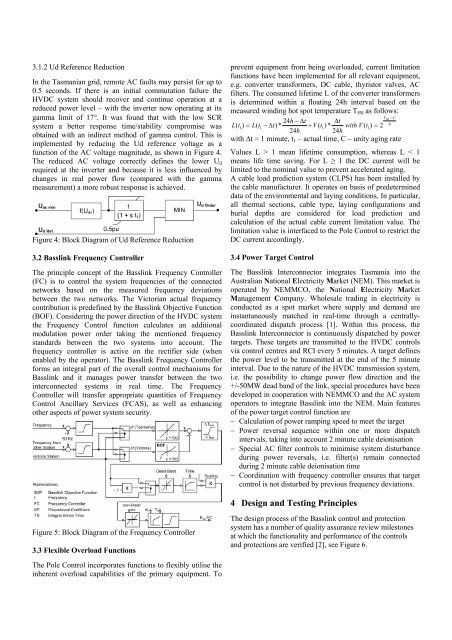
3.1.2 Ud Reference Reduction<br />
In <strong>the</strong> Tasmanian grid, remote AC faults may persist for up <strong>to</strong><br />
0.5 seconds. If <strong>the</strong>re is an initial commutation failure <strong>the</strong><br />
HVDC system should recover <strong>and</strong> continue operation at a<br />
reduced power level – with <strong>the</strong> inverter now operating at its<br />
gamma limit of 17°. It was found that with <strong>the</strong> low SCR<br />
system a better response time/stability compromise was<br />
obtained with an indirect method of gamma control. This is<br />
implemented by reducing <strong>the</strong> Ud reference voltage as a<br />
function of <strong>the</strong> AC voltage magnitude, as shown in Figure 4.<br />
The reduced AC voltage correctly defines <strong>the</strong> lower U d<br />
required at <strong>the</strong> inverter <strong>and</strong> because it is less influenced by<br />
changes in real power flow (compared with <strong>the</strong> gamma<br />
measurement) a more robust response is achieved.<br />
Figure 4: Block Diagram of Ud Reference Reduction<br />
3.2 Basslink Frequency <strong>Control</strong>ler<br />
The principle concept of <strong>the</strong> Basslink Frequency <strong>Control</strong>ler<br />
(FC) is <strong>to</strong> control <strong>the</strong> system frequencies of <strong>the</strong> connected<br />
networks based on <strong>the</strong> measured frequency deviations<br />
between <strong>the</strong> two networks. The Vic<strong>to</strong>rian actual frequency<br />
contribution is predefined by <strong>the</strong> Basslink Objective Function<br />
(BOF). Considering <strong>the</strong> power direction of <strong>the</strong> HVDC system<br />
<strong>the</strong> Frequency <strong>Control</strong> function calculates an additional<br />
modulation power order taking <strong>the</strong> mentioned frequency<br />
st<strong>and</strong>ards between <strong>the</strong> two systems in<strong>to</strong> account. The<br />
frequency controller is active on <strong>the</strong> rectifier side (when<br />
enabled by <strong>the</strong> opera<strong>to</strong>r). The Basslink Frequency <strong>Control</strong>ler<br />
forms an integral part of <strong>the</strong> overall control mechanisms for<br />
Basslink <strong>and</strong> it manages power transfer between <strong>the</strong> two<br />
interconnected systems in real time. The Frequency<br />
<strong>Control</strong>ler will transfer appropriate quantities of Frequency<br />
<strong>Control</strong> Ancillary Services (FCAS), as well as enhancing<br />
o<strong>the</strong>r aspects of power system security.<br />
prevent equipment from being overloaded, current limitation<br />
functions have been implemented for all relevant equipment,<br />
e.g. converter transformers, DC cable, thyris<strong>to</strong>r valves, AC<br />
filters. The consumed lifetime L of <strong>the</strong> converter transformers<br />
is determined within a floating 24h interval based on <strong>the</strong><br />
measured winding hot spot temperature T HS as follows:<br />
T<br />
24<br />
HS −C<br />
h − ∆t<br />
∆t<br />
6<br />
L(<br />
t1)<br />
= L(<br />
t1<br />
− ∆t) * + V ( t1) * with V ( t1)<br />
= 2<br />
24h<br />
24h<br />
with ∆t = 1 minute, t 1 – actual time, C – unity aging rate<br />
Values L > 1 mean lifetime consumption, whereas L < 1<br />
means life time saving. For L ≥ 1 <strong>the</strong> DC current will be<br />
limited <strong>to</strong> <strong>the</strong> nominal value <strong>to</strong> prevent accelerated aging.<br />
A cable load prediction system (CLPS) has been installed by<br />
<strong>the</strong> cable manufacturer. It operates on basis of predetermined<br />
data of <strong>the</strong> environmental <strong>and</strong> laying conditions. In particular,<br />
all <strong>the</strong>rmal sections, cable type, laying configurations <strong>and</strong><br />
burial depths are considered for load prediction <strong>and</strong><br />
calculation of <strong>the</strong> actual cable current limitation value. The<br />
limitation value is interfaced <strong>to</strong> <strong>the</strong> Pole <strong>Control</strong> <strong>to</strong> restrict <strong>the</strong><br />
DC current accordingly.<br />
3.4 Power Target <strong>Control</strong><br />
The Basslink Interconnec<strong>to</strong>r integrates Tasmania in<strong>to</strong> <strong>the</strong><br />
Australian National Electricity Market (NEM). This market is<br />
operated by NEMMCO, <strong>the</strong> National Electricity Market<br />
Management Company. Wholesale trading in electricity is<br />
conducted as a spot market where supply <strong>and</strong> dem<strong>and</strong> are<br />
instantaneously matched in real-time through a centrallycoordinated<br />
dispatch process [1]. Within this process, <strong>the</strong><br />
Basslink Interconnec<strong>to</strong>r is continuously dispatched by power<br />
targets. These targets are transmitted <strong>to</strong> <strong>the</strong> HVDC controls<br />
via control centres <strong>and</strong> RCI every 5 minutes. A target defines<br />
<strong>the</strong> power level <strong>to</strong> be transmitted at <strong>the</strong> end of <strong>the</strong> 5 minute<br />
interval. Due <strong>to</strong> <strong>the</strong> nature of <strong>the</strong> HVDC transmission system,<br />
i.e. <strong>the</strong> possibility <strong>to</strong> change power flow direction <strong>and</strong> <strong>the</strong><br />
+/-50MW dead b<strong>and</strong> of <strong>the</strong> link, special procedures have been<br />
developed in cooperation with NEMMCO <strong>and</strong> <strong>the</strong> AC system<br />
opera<strong>to</strong>rs <strong>to</strong> integrate Basslink in<strong>to</strong> <strong>the</strong> NEM. Main features<br />
of <strong>the</strong> power target control function are<br />
− Calculation of power ramping speed <strong>to</strong> meet <strong>the</strong> target<br />
− Power reversal sequence within one or more dispatch<br />
intervals, taking in<strong>to</strong> account 2 minute cable deionisation<br />
− Special AC filter controls <strong>to</strong> minimise system disturbance<br />
during power reversals, i.e. filter(s) remain connected<br />
during 2 minute cable deionisation time<br />
− Coordination with frequency controller ensures that target<br />
control is not disturbed by previous frequency deviations.<br />
4 Design <strong>and</strong> Testing Principles<br />
Figure 5: Block Diagram of <strong>the</strong> Frequency <strong>Control</strong>ler<br />
3.3 Flexible Overload Functions<br />
The design process of <strong>the</strong> Basslink control <strong>and</strong> protection<br />
system has a number of quality assurance review miles<strong>to</strong>nes<br />
at which <strong>the</strong> functionality <strong>and</strong> performance of <strong>the</strong> controls<br />
<strong>and</strong> protections are verified [2], see Figure 6.<br />
The Pole <strong>Control</strong> incorporates functions <strong>to</strong> flexibly utilise <strong>the</strong><br />
inherent overload capabilities of <strong>the</strong> primary equipment. To